intelligent pressure transmitter with remote-sealed ... pressure transmitter with remote-sealed...
TRANSCRIPT

1
CS・3253-805
EPR-N8S Pressure Transmitter with Remote-Sealed Diaphragm incorporates semiconductor sensors and a microcomputer and converts measured differential pressures to 4 to 20mA DC signals with high accuracy. EPR-N8S is suitable for measuring pressures of various types of process fluids such as gas, liquid and steam and also supports various installation environments such as explosion-prevented areas.
STANDARD SPECIFICATIONS
Model EPR-N8S
Pressure range
Range
Code Measuring Span Settable Range Limits
G20 98kPa to 2MPa -101.3kPa≦LRV≦2MPa,-101.3kPa≦URV≦2MPa
G100 0.98 to 10MPa -101.3kPa≦LRV≦10MPa,-101.3kPa≦URV≦10MPa
G500※ 10 to 30MPa -101.3kPa≦LRV≦30MPa,-101.3kPa≦URV≦30MPa
* When working pressure is more than 30MPa in range code G500, Please contact us separately.
Note) URV is the input differential pressure to give 100% output (20mA DC)
LRV is the input differential pressure to give 0% output (4mA DC)
Output signal 4 to 20mA DC
Output signal range 3.6 to 21.6mA DC (-2.5 to 110%)
Power supply voltage 11.4 to 42.0V DC
Allowable load resistance 600Ω (at 24V DC power supply voltage)
Communication protocol Hitachi communication
Communication line conditions
Power supply voltage 16.7 to 42.0V DC
Load resistance 250 to 1.2kΩ
See Fig. 1 for the relationship between power supply voltage and load resistance.
External adjustment/
Configuration
Zero point adjustment (±100% of measured span), LRV and URV adjustment and configuration and damping time constant are configurable (however, only with indicator and when the function is enabled).
Burn-out at error Burn-up, burn-down or no burn-out can be selected. (No burn-out is configured at shipment.)
Accuracy
●Material Code:Standard, 316L
Range
Code Accuracy
G20 ±0.15%
±[0.1+(0.05×0.2/X)]%
X is 0.2MPa or higher
X is less than 0.2MPa
G100 ±0.15%
G500 ±0.2%
Note) Accuracy is the percentage to X. X is the absolute value of URV, LRV or the biggest value of measured span. X’s unit is MPa.
Response time
Dead time 0.15s (Minimum) Damping time constant (Amplifier time constant)
Electrically configurable from 0.1 to 102.4s (at 0.1s step) by using a communicator.
・Response time is the sum of time constants of the Sensor body and damping time constant (amplifier time constant) and dead time.
Storage temperature range
-40 to 85℃
Operating humidity range
0 to 100%RH
Operating temperature range
Ambient temperature range
-40 to 85℃
Wetted parts temperature range
-40 to 180℃
Maximum operating pressure
The highest or below operating pressure of flange
(See Fig. 2 for negative pressure.)
Site vibration Continuous vibration below 29.4m/s2
Intelligent Pressure Transmitter with
Remote-Sealed Diaphragm
EPR-N8S

2 CS・3253-805
Temperature characteristics (at -20 to 60℃)
●Material Code:Standard, 316L
Range
Code Temperature characteristics
G20
Zero shift
Total shift
±[0.05+(0.3×T/50)]%
±[0.05+(0.15+0.15×1/X)×T/50]%
±[0.05+(0.55×T/50)]%
±[0.05+(0.4+0.15×1/X)×T/50]%
X is 1MPa or higher
X is less than 1MPa
X is 1MPa or higher
X is less than 1MPa
G100
Zero shift
Total shift
±[0.05+(0.3×T/50)]%
±[0.05+(0.15+0.15×5/X)×T/50]%
±[0.05+(0.55×T/50)]%
±[0.05+(0.4+0.15×5/X)×T/50]%
X is 5MPa or higher
X is less than 5MPa
X is 5MPa or higher
X is less than 5MPa
G500 Zero shift
Total shift
±[0.05+(0.3×T/50)]%
±[0.05+(0.55×T/50)]%
X is 10MPa or higher
X is 10MPa or higher
Note) Temperature characteristic is the percentage to X. X is the absolute value of URV, LRV or the biggest value of measured span. X’s unit is MPa. T (℃) is temperature variation width.
Materials
Diaphragm SUS316L
Wetted parts other than diaphragm
SUS316
Standard flange SUS304 or SUSF304
Capillary SUS316(polyethylene-covered)
Note) No polyethylene cover for Wetted parts condition Code: WVT
Sensor body flange bolt
SCM435
Amplifier case Aluminum alloy
Mounting plate SPCC (anti-acid painting)
U-bolt SUS304
Sealed liquid Silicone oil (Relative density: 0.955 at 25℃)
Process connection
JIS 10K 80A RF (similar flange)
Length of protruding part of flange
0mm
Capillary length 5m
Capillary ejection direction
Wafer type (Horizontal to side of diaphragm)
Wire connection G1/2
Check terminal Current output (Ampere meter is required for measurement.)
Protection grade JIS C 0920 IP67
Surge absorber Incorporated into the power input circuit Surge tolerance:1,000A (8/20μs) Impact test voltage:15,000V (1.2/50μs)
Color Light gray (anti-acid painting)
Weight Approx. 10kg
Mounting Use U-bolts for 50A pipes, etc.
Accessories A set of 50A pipe mounting plate and U-bolts, External adjustment/configuration magnet
ADDITIONAL SPECIFICATIONS
Communication protocol
HART communication
TIIS flameproof, Oil-immersion
Applicable Standard Exdo II CT4 X Note) Available for use at Zone1,Zone2 groups of hazardous place.
Note) If the indicator is not equipped, please construct an external alarm indication system by scaling out of
the output signal.
Operating temperature range
Ambient temperature range:-20 to 55℃
System surface temperature:-20 to 100℃
Wire connection Please use X-EXRCA pressure proof packing brackets (or EXPC-16B by Shimada Electric Co.,Ltd).
FM explosionproof approval (Arranging)
Applicable Standard Explosionproof CLI,DIV 1,GPS B,C&D Dust-ignition proof CLⅡ/Ⅲ,GPS E,F&G Temperature Code T4
Applicable Standard Explosionproof CLI,DIV 1,GPS B,C&D Dust-ignition proof CLⅡ/Ⅲ,GPS E,F&G Temperature Code T4
NEPSI explosionproof approval (Arranging)
Applicable Standard Explosionproof Ex d ⅡC T4
Operating temperature range
Ambient temperature range: -40 to 60℃ Wetted parts temperature range: -40 to 120℃
Indicator Digital indicator Indication 5 digits,unit 7 digits,bar graph
Indication items Individual enable/disable indication of the following items: Automatic switching when selecting the items
Differential pressure%, Differential pressure value, Actual scale of differential pressure, Static pressure%, Static pressure value
Actual scale Unit is selected from pressure,
flow volume,height or discretionary configuration. Configuration range: -99,999 to 99,999
Ambient temperature range: -20 to 85℃
Process connection JIS 20K, ANSI 150, ANSI 300, JPI 150, JPI 300, etc. Connection aperture:80A(3B), 100A(4B) (See Code table for details.)
Length of protruding part of flange
50mm, 100mm, 150mm
Diaphragm for protection and adherence prevention
(Only for aperture 80A(3B) without protruding part)
Material:FEP (Operating pressure:Atmospheric pressure or higher, operating temperature: -10 to 120℃) ±0.5% is added to the accuracy when the diaphragm cover is used.
Capillary length 1 to 10m (Unit: 1m)
Capillary ejection direction
Back ejection (Vertical to side of diaphragm)

3
CS・3253-805
Sealed liquid
Fluorine oil Wetted parts temperature range: -20 to 120℃
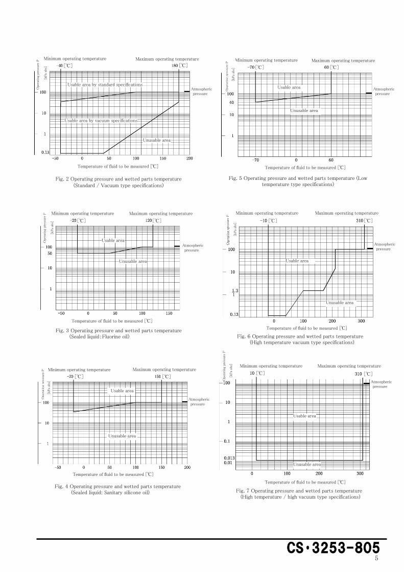
Relative density:1.860(at 20℃) (See Fig. 3 for negative pressure.) Specify also the oil-prohibitive finish together for oxygen measurement.
Sanitary Silicone oil
Wetted parts temperature range: -20 to 150℃
Relative density:0.965(at 25℃) (See Fig. 4 for negative pressure.)
Propylene glycol
Wetted parts temperature range: -20 to 150℃
Relative density:1.037(at 25℃) (Not available for negative pressure.)
Wetted parts finish
Oil prohibitive or oil and water prohibitive finish
Wetted parts condition
High temperature type (Code:HT)
Wetted parts temperature range: -10 to 310℃
Ambient temperature range: -10 to 85℃
Relative density of sealed liquid:1.065(at 25℃) (Operating pressure is atmospheric pressure or higher)
Low temperature type (Code:LT)
Wetted parts temperature range: -70 to 60℃
Ambient temperature range: -20 to 60℃
Relative density of sealed liquid:0.873(at 25℃) (See Fig. 5 for negative pressure.)
Vacuum type
(Code:V)
Wetted parts temperature range: -40 to 180℃
Ambient temperature range: -20 to 85℃
Sealed liquid is the same as standard specifications. (Operable pressure varies depending on the temperature. See Fig. 2 for proper usage.)
Wafer type High temperature vacuum type (Code:WVT)
Wetted parts temperature range: -10 to 310℃
Ambient temperature range: -10 to 85℃
Relative density of sealed liquid:1.065(at 25℃) (Operable pressure varies depending on the temperature. See Fig. 6 for proper usage.) Note) Capillary is not polyethylene-covered.
High temperature vacuum type (Code:VT)
Wetted parts temperature range: -10 to 310℃
Ambient temperature range: -10 to 85℃
Relative density of sealed liquid:0.955(at 25℃) However, 1.065 at the tip (Operable pressure varies depending on the temperature. See Fig. 6 for proper usage.)
High Temperature / high vacuum type (Code:SVT)
Wetted parts temperature range: 10 to 310℃
Ambient temperature range: -10 to 85℃
Relative density of sealed liquid:0.955(at 25℃) However, 1.079 at the tip Negative pressure is allowed up to 0.0133 kPa abs. (See Fig. 7.)
Wetted parts materials
Material Code Diaphragm Wetted parts except for diaphragm
316L SUS316L SUS316L
HC Hastelloy C Hastelloy C
TA Tantalum Tantalum
Note) Protruding part length of 0mm is only manufactured for the Material Code TA.
* Select a material considering the anti-corrosion characteristics. Using gold-plated diaphragm (Code: Z52) or embedded with gold-plated diaphragm + hydrogen absorbing alloy (Code:Z72)is recommended if there is any concern about the error caused by hydrogen permeation of diaphragm due to hydrogen in the measured fluid, etc. (However, it is difficult for Z52 and Z72 to completely prevent the error caused by hydrogen permeation.)
Bolt material Sensor body flange bolt:SUS630
Accuracy
●Material Code:HC,TA
(Wetted parts condition Code:VT,SVT are not included)
Range Code
Accuracy
G20 ±0.2%
±[0.15+(0.05×0.2/X)]%
X is 0.2MPa or higher
X is less than 0.2MPa
G100 ±0.2%
Note) Accuracy is the percentage to X. X is the absolute value of URV, LRV or the biggest value of measured span. X’s unit is MPa.
●Wetted parts condition Code:VT, SVT
Range Code
Accuracy
G20
±0.5% G100
G500
Temperature characteristics (at -20 to 60℃)
●Material Code:HC, TA
Range Code
Temperature characteristics
G20 Zero shift
Total shift
±[0.1+(0.5×T/50)]%
±[0.1+(0.25+0.25×1/X)×T/50]%
±[0.1+(1.0×T/50)]%
±[0.1+(0.5+0.5×1/X)×T/50]%
X is 1MPa or higher
X is less than 1MPa
X is 1MPa or higher
X is less than 1MPa
G100 Zero shift
Total shift
±[0.1+(0.5×T/50)]%
±[0.1+(0.25+0.25×5/X)×T/50]%
±[0.1+(1.0×T/50)]%
±[0.1+(0.5+0.5×5/X)×T/50]%
X is 5MPa or higher
X is less than 5MPa
X is 5MPa or higher
X is less than 5M Pa
Note) Temperature characteristic is the percentage to X. X is the absolute value of URV, LRV or the biggest value of measured span. X’s unit is MPa. T (℃) is temperature variation width.

4 CS・3253-805
SMALL APERTURE FLANGE CONNECTION
Pressure range
Range Code
Measuring
Span Settable Range Limits
G20 0.2 to 2MPa -98kPa≦LRV≦2MPa,-98 kPa≦URV≦2MPa
G100 1 to 10MPa -98kPa≦LRV≦1MPa,-98 kPa≦URV≦1MPa
G500※ 10 to 30MPa -98kPa≦LRV≦30MPa,-98kPa≦URV≦30MPa
* Consult our nearest agency, distributor, or sales office when the operating pressure for the Range Code of G500 is 30 MPa or higher.
Accuracy
Aperture
Accuracy
(Measuring
Span or
higher)
Operating temperature Range
Protruding part length Wetted parts
temperature
Ambient
temperature
25A(1B) ±0.5% -20 to 180℃ -10 to 60℃ Only E0
(Protruding not allowed)
40A(1.5B) ±0.5% -20 to 180℃ -10 to 60℃ E0,E>0
50A(2B)
±0.2%
-20 to 180℃
-20 to 85℃ E0
±0.5% -10 to 60℃ E>0
Temperature characteristics
Aperture Temperature characteristics Protruding part
length
25A(1B) Standard specifications×3 Only E0
40A
(1.5B)
Standard specifications×2 E0
Standard specifications×3 E>0
50A
(2B)
Same as standard
specifications E0
Standard specifications×2 E>0
Effect of temperature difference
Aperture
Effect value
Protruding part
length
Wetted parts temperature difference
(varied at 10℃)
Capillary temperature
difference
(1m,10℃ varied)
25A(1B) 1.6kPa 1.3kPa Only E0
40A
(1.5B)
0.6kPa 0.4kPa E0
2.0kPa 1.3kPa E>0
50A
(2B)
0.2kPa 0.1kPa E0
0.8kPa 0.4kPa E>0
Operating temperature range
Ambient temperature range
-10 to 60℃
(−20 to 85℃ for aperture 50 (2B),E0)
Wetted parts temperature range
-20 to 180℃
Storage temperature range
-40 to 85℃
Process connection
JIS 10K, 20K, 30K, 63K ANSI 150, 300 JPI 150, 300, etc. Connection aperture: 25A(1B), 40A(1.5B), 50A(2B)
(See Code table for details.)
Length of protruding part of flange
0mm, 50mm, 100mm, 150mm
(Only 0mm is available for 25A (1B).)
Diaphragm cover
(Only for aperture 2B(50A) without protruding part)
Material:FEP
(Operating pressure:atmospheric pressure or higher, Operating temperature:-10 to 120℃)
±0.8% is added to the accuracy when the diaphragm cover is used.
Wetted parts conditions
High temperature type
(Code:HT)
Wetted parts temperature range:-10 to 310℃
Ambient temperature range:-10 to 60℃
Relative density of sealed liquid:1.065(at 25℃)
(Operating pressure is atmospheric pressure or higher)
Low temperature type
(Code:LT)
Wetted parts temperature range:-70 to 60℃
Ambient temperature range:-20 to 60℃
Relative density of sealed liquid:0.873(at 25℃)
(See Fig. 5 for negative pressure.)
Vacuum type
(Code:V)
Wetted parts temperature range:-40 to 180℃
Ambient temperature range:-10 to 60℃
Sealed liquid is the same as standard specifications.
(Operating pressure varies depending on the temperature. See Fig. 2 for proper usage.)
Fig. 1 Power supply voltage / load resistance characteristics
0 0
250
600
1200
11.4 16.7
Load
res
ista
nce
[Ω
]
24.0 42.0 Power supply voltage [V DC]
Usable range
Unusable range
36.6V
The minimum load resistance of 250Ω is required to
communicate by connecting the communicator.
5
CS・3253-805
Fig. 2 Operating pressure and wetted parts temperature (Standard / Vacuum type specifications)
Fig. 6 Operating pressure and wetted parts temperature (High temperature vacuum type specifications)
Maximum operating temperature Minimum operating temperature
Atmospheric pressure
Oper
atin
g pre
ssure
P
Usable area by standard specifications
Usable area by vacuum specifications
Temperature of fluid to be measured [℃]
Unusable area
Usable area
Usable area
Unusable area
Ope
rating
pre
ssure
P Minimum operating temperature Maximum operating temperature
Atmospheric pressure
Unusable area
Temperature of fluid to be measured [℃]
Fig. 3 Operating pressure and wetted parts temperature (Sealed liquid:Fluorine oil)
Fig. 4 Operating pressure and wetted parts temperature (Sealed liquid: Sanitary silicone oil)
Ope
rating
pre
ssur
e P Minimum operating temperature Maximum operating temperature
Atmospheric pressure
Unusable area
Usable area
Temperature of fluid to be measured [℃]
Minimum operating temperature Maximum operating temperature
Oper
atin
g pre
ssure
P
Atmospheric pressure
Temperature of fluid to be measured [℃]
Fig. 5 Operating pressure and wetted parts temperature (Low temperature type specifications)
Fig. 7 Operating pressure and wetted parts temperature (High temperature / high vacuum type specifications)
Minimum operating temperature Maximum operating temperature
Ope
rating
pre
ssure
P
Atmospheric pressure
Usable area
Unusable area
Temperature of fluid to be measured [℃]
Ope
rating
pre
ssur
e P
Minimum operating temperature Maximum operating temperature
Atmospheric pressure
Temperature of fluid to be measured [℃]
Usable area
Unusable area
[℃]
[℃]
[℃]
[℃]
[℃]
[℃]
[℃]
[℃]
[℃]
[℃]
[℃]
[℃]
[kPa
abs]
[kPa
abs]
[kPa
abs]
[kPa
abs]
[k
Pa
abs]
[kPa
abs]

6 CS・3253-805
Without on-site indicator Connected with on-site indicator
Note1) Perform Class D grounding work (ground resistance of 100Ω or less) for grounding.
Note2) Ground either the transmitter or the receiving instrument. Be careful not to be dual-grounded.
Note3) Grounding terminals on the transmitter are located inside the terminal box and outside the amplifier case.
You can use either of the groundings.
Note4) T1,T2 and T3 terminals are not connected.
Note5) The resistance value needs to be 20Ω or less including wire resistance to connect an on-site indicator.
EXTERNAL CONNECTION DRAWING
Load
Power supply
Grounding Grounding On-site indicator
Load
Power supply

7
CS・3253-805
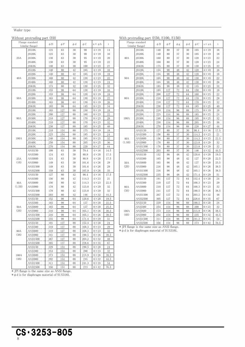
Without protruding part (E0)
With protruding part (E50, E100, E150)
OUTLINE DRAWING (Unit:mm)
Wafer type
Protruding length
E
50
100
150
Wet side
Diaphragm diameter φ d
8 CS・3253-805
Without protruding part (E0)
Flange standard
(similar flange) φD φF φd φC n×φh t
25A
JIS10K 125 63 30 90 4×19 14
JIS20K 125 63 30 90 4×19 16
JIS30K 130 63 30 95 4×19 20
JIS40K 130 63 30 95 4×19 22
JIS63K 140 63 30 100 4×23 27
40A
JIS10K 140 80 42 105 4×19 16
JIS20K 140 80 42 105 4×19 18
JIS30K 160 80 42 120 4×23 22
JIS40K 160 80 42 120 4×23 24
JIS63K 175 80 42 130 4×25 32
50A
JIS10K 155 98 64 120 4×19 16
JIS20K 155 98 64 120 8×19 18
JIS30K 165 98 64 130 8×19 22
JIS40K 165 98 64 130 8×19 26
JIS63K 185 98 64 145 8×23 34
80A
JIS10K 185 127 88 150 8×19 18
JIS20K 200 127 88 160 8×23 22
JIS30K 210 127 88 170 8×23 28
JIS40K 210 127 88 170 8×23 32
JIS63K 230 127 88 185 8×25 40
100A
JIS10K 210 154 88 175 8×19 18
JIS20K 225 154 88 185 8×23 24
JIS30K 240 154 88 195 8×25 32
JIS40K 250 154 88 205 8×25 36
JIS63K 270 154 88 220 8×27 44
25A
(1B)
ANSI150 108 63 30 79.4 4×16 14.5
ANSI300 124 63 30 88.9 4×20 17.5
ANSI600 124 63 30 88.9 4×20 17.5
ANSI900 149 63 30 101.6 4×26 29
ANSI1500 149 63 30 101.6 4×26 29
ANSI2500 159 63 30 107.9 4×26 35
40A
(1.5B)
ANSI150 127 80 42 98.4 4×16 17.5
ANSI300 156 80 42 114.3 4×23 21
ANSI600 156 80 42 114.3 4×23 22.5
ANSI900 178 80 42 123.8 4×29 32
ANSI1500 178 80 42 123.8 4×29 32
ANSI2500 203 80 42 146 4×32 44.5
50A
(2B)
ANSI150 152 98 64 120.6 4×20 19.5
ANSI300 165 98 64 127 8×20 22.5
ANSI600 165 98 64 127 8×20 25.5
ANSI900 216 98 64 165.1 8×26 38.5
ANSI1500 216 98 64 165.1 8×26 38.5
ANSI2500 235 98 64 171.4 8×29 51
80A
(3B)
ANSI150 191 127 88 152.4 4×20 24
ANSI300 210 127 88 168.3 8×23 29
ANSI600 210 127 88 168.3 8×23 32
ANSI900 241 127 88 190.5 8×26 38.5
ANSI1500 267 127 88 203.2 8×32 48
ANSI2500 305 127 88 228.6 8×35 67
100A
(4B)
ANSI150 229 154 88 190.5 8×20 24
ANSI300 254 154 88 200 8×23 32
ANSI600 273 154 88 215.9 8×26 38.5
ANSI900 292 154 88 235 8×32 44.5
ANSI1500 311 154 88 241.3 8×35 54
ANSI2500 356 154 88 273 8×42 76.5
* JPI flange is the same size as ANSI flange. *φd is for diaphragm material of SUS316L
With protruding part (E50, E100, E150)
Flange standard
(similar flange) φD φF φg φd φC n×φh t
40A
JIS10K 140 80 37 30 105 4×19 16
JIS20K 140 80 37 30 105 4×19 18
JIS30K 160 80 37 30 120 4×23 22
JIS40K 160 80 37 30 120 4×23 24
JIS63K 175 80 37 30 130 4×25 32
50A
JIS10K 155 98 48 42 120 4×19 16
JIS20K 155 98 48 42 120 8×19 18
JIS30K 165 98 48 42 130 8×19 22
JIS40K 165 98 48 42 130 8×19 26
JIS63K 185 98 48 42 145 8×23 34
80A
JIS10K 185 127 72 64 150 8×19 18
JIS20K 200 127 72 64 160 8×23 22
JIS30K 210 127 72 64 170 8×23 28
JIS40K 210 127 72 64 170 8×23 32
JIS63K 230 127 72 64 185 8×25 40
100A
JIS10K 210 154 96 88 175 8×19 18
JIS20K 225 154 96 88 185 8×23 24
JIS30K 240 154 96 88 195 8×25 32
JIS40K 250 154 96 88 205 8×25 36
JIS63K 270 154 96 88 220 8×27 44
40A
(1.5B)
ANSI150 127 80 37 30 98.4 4×16 17.5
ANSI300 156 80 37 30 114.3 4×23 21
ANSI600 156 80 37 30 114.3 4×23 22.5
ANSI900 178 80 37 30 123.8 4×29 32
ANSI1500 178 80 37 30 123.8 4×29 32
ANSI2500 203 80 37 30 146 4×32 44.5
50A
(2B)
ANSI150 152 98 48 42 120.6 4×20 19.5
ANSI300 165 98 48 42 127 8×20 22.5
ANSI600 165 98 48 42 127 8×20 25.5
ANSI900 216 98 48 42 165.1 8×26 38.5
ANSI1500 216 98 48 42 165.1 8×26 38.5
ANSI2500 235 98 48 42 171.4 8×29 51
80A
(3B)
ANSI150 191 127 72 64 152.4 4×20 24
ANSI300 210 127 72 64 168.3 8×23 29
ANSI600 210 127 72 64 168.3 8×23 32
ANSI900 241 127 72 64 190.5 8×26 38.5
ANSI1500 267 127 72 64 203.2 8×32 48
ANSI2500 305 127 72 64 228.6 8×35 67
100A
(4B)
ANSI150 229 154 96 88 190.5 8×20 24
ANSI300 254 154 96 88 200 8×23 32
ANSI600 273 154 96 88 215.9 8×26 38.5
ANSI900 292 154 96 88 235 8×32 44.5
ANSI1500 311 154 96 88 241.3 8×35 54
ANSI2500 356 154 96 88 273 8×42 76.5
* JPI flange is the same size as ANSI flange. *φd is for diaphragm material of SUS316L
Wafer type

9
CS・3253-805
Without protruding part (E0)
With protruding part (E50, E100, E150)
Back ejection type
Protruding length
E
50
100
150

10 CS・3253-805
Without protruding part (E=0)
Flange standard
(similar flange) φD φF φd φC n×φh t f
50A
JIS10K 155 96 64 120 4×19 16 2
JIS20K 155 96 64 120 8×19 18 2
JIS30K 165 105 64 130 8×19 22 2
JIS40K 165 105 64 130 8×19 26 2
JIS63K 185 105 64 145 8×23 34 2
80A
JIS10K 185 127 88 150 8×19 18 2
JIS20K 200 127 88 160 8×23 22 2
JIS30K 210 127 88 170 8×23 28 2
JIS40K 210 127 88 170 8×23 32 2
JIS63K 230 127 88 185 8×25 40 2
100A
JIS10K 210 151 88 175 8×19 18 2
JIS20K 225 160 88 185 8×23 24 2
JIS30K 240 160 88 195 8×25 32 2
JIS40K 250 165 88 205 8×25 36 2
JIS63K 270 165 88 220 8×27 44 2
50A
(2B)
ANSI150 152 92 64 120.6 4×19 19.1 1.6
ANSI300 165 92 64 127 8×19 22.4 1.6
ANSI600 165 92 64 127 8×19 31.8 6.4
ANSI900 216 92 64 165 8×26 44.5 6.4
ANSI1500 216 92 64 165 8×26 44.5 6.4
ANSI2500 235 92 64 171.4 8×29 58 6.4
80A
(3B)
ANSI150 191 127 88 152.4 4×20 23.9 1.6
ANSI300 210 127 88 168.1 8×23 28.5 1.6
ANSI600 210 127 88 168.1 8×23 38.3 6.4
ANSI900 241 127 88 1905 8×26 44.5 6.4
ANSI1500 267 127 88 203.2 8×32 54.2 6.4
ANSI2500 305 127 88 228.6 8×35 73 6.4
100A
(4B)
ANSI150 229 157 88 190.5 8×20 23.9 1.6
ANSI300 254 157 88 200.2 8×23 31.8 1.6
ANSI600 273 157 88 215.9 8×26 44.5 6.4
ANSI900 292 157 88 235 8×32 50.9 6.4
ANSI1500 311 157 88 241.3 8×35 60.4 6.4
ANSI2500 356 157 88 273 8×42 82.6 6.4
* JPI flange is the same size as ANSI flange.
*φd is for diaphragm material of SUS316L
Item Code S
Wet condition
No additional specifications 70
HT 170
LT 120
V 70
With protruding part (E>0)
Flange standard
(similar flange) φD φF φd φC n×φh t f
80A
JIS10K 185 127 64 150 8×19 18 2 JIS20K 200 127 64 160 8×23 22 2 JIS30K 210 127 64 170 8×23 28 2 JIS40K 210 127 64 170 8×23 32 2 JIS63K 230 127 64 185 8×25 40 2
100A
JIS10K 210 151 88 175 8×19 18 2 JIS20K 225 160 88 185 8×23 24 2 JIS30K 240 160 88 195 8×25 32 2 JIS40K 250 165 88 205 8×25 36 2 JIS63K 270 165 88 220 8×27 44 2
80A (3B)
ANSI150 191 127 64 152.4 4×20 23.9 1.6 ANSI300 210 127 64 168.1 8×23 28.5 1.6 ANSI600 210 127 64 168.1 8×23 38.3 6.4 ANSI900 241 127 64 190.5 8×26 44.5 6.4 ANSI1500 267 127 64 203.2 8×32 54.2 6.4 ANSI2500 305 127 64 228.6 8×35 73 6.4
100A (4B)
ANSI150 229 157 88 190.5 8×20 23.9 1.6 ANSI300 254 157 88 200.2 8×23 31.8 1.6 ANSI600 273 157 88 215.9 8×26 44.5 6.4 ANSI900 292 157 88 235 8×32 50.9 6.4 ANSI1500 311 157 88 241.3 8×35 60.4 6.4 ANSI2500 356 157 88 273 8×42 82.6 6.4
* JPI flange is the same size as ANSI flange. *φd is for diaphragm material of SUS316L
Back ejection type

11
CS・3253-805
Without protruding part (E0)
With protruding part (E50, E100, E150)
VT,SVT type
Protruding length
E
50
100
150

12 CS・3253-805
Without protruding part (E=0)
Flange standard (similar
flange) φD φF φd φC n×φh t f
80A
JIS10K 185 127 88 150 8×19 18 2
JIS20K 200 127 88 160 8×23 22 2
JIS30K 210 127 88 170 8×23 28 2
JIS40K 210 127 88 170 8×23 32 2
JIS63K 230 127 88 185 8×25 40 2
100A
JIS10K 210 151 88 175 8×19 18 2
JIS20K 225 160 88 185 8×23 24 2
JIS30K 240 160 88 195 8×25 32 2
JIS40K 250 165 88 205 8×25 36 2
JIS63K 270 165 88 220 8×27 44 2
80A
(3B)
ANSI150 191 127 88 152.4 4×20 23.9 1.6
ANSI300 210 127 88 168.1 8×23 28.5 1.6
ANSI600 210 127 88 168.1 8×23 38.3 6.4
ANSI900 241 127 88 1905 8×26 44.5 6.4
ANSI1500 267 127 88 203.2 8×32 54.2 6.4
ANSI2500 305 127 88 228.6 8×35 73 6.4
100A
(4B)
ANSI150 229 157 88 190.5 8×20 23.9 1.6
ANSI300 254 157 88 200.2 8×23 31.8 1.6
ANSI600 273 157 88 215.9 8×26 44.5 6.4
ANSI900 292 157 88 235 8×32 50.9 6.4
ANSI1500 311 157 88 241.3 8×35 60.4 6.4
ANSI2500 356 157 88 273 8×42 82.6 6.4
* JPI flange is the same size as ANSI flange.
*φd is for diaphragm material of SUS316L.
With protruding part (E>0)
Flange standard (similar
flange) φD φF φd φC n×φh t f
100A
JIS10K 210 151 88 175 8×19 18 2
JIS20K 225 160 88 185 8×23 24 2
JIS30K 240 160 88 195 8×25 32 2
JIS40K 250 165 88 205 8×25 36 2
JIS63K 270 165 88 220 8×27 44 2
100A
(4B)
ANSI150 229 157 88 190.5 8×20 23.9 1.6
ANSI300 254 157 88 200.2 8×23 31.8 1.6
ANSI600 273 157 88 215.9 8×26 44.5 6.4
ANSI900 292 157 88 235 8×32 50.9 6.4
ANSI1500 311 157 88 241.3 8×35 60.4 6.4
ANSI2500 356 157 88 273 8×42 82.6 6.4
* JPI flange is the same size as ANSI flange.
*φd is for diaphragm material of SUS316L.
VT,SVT type

13
CS・3253-805
EPR-N8S Intelligent Pressure Transmitter with Remote-Sealed Diaphragm
Model
EPR-N8S
No. Item Code Remarks
1 Range Code G20 Measuring span 98kPa to 2MPa
G100 Measuring span 0.98 to 10MPa
G500 Measuring span 10 to 30MPa
2 Communication - Hitachi communication
H HART communication
3 Functional safety - None
4 Adjustment range - Adjust between 0 and Maximum range
C( ) Describe adjustment range and unit sign in ( )
5 Certification - None
XC TIIS flameproof, Oil-immersion
FM FM explosionproof approval (Arranging)
NEPSI NEPSI explosionproof approval (Arranging)
6 Indicator - None
M With digital indicator (Indication 0 to 100%)
MJ( ) With digital indicator, describe indication scale and unit sign in actual scale indication ( )
7
Flange standard
JIS
25J10 Flange standard JIS 10K 25A RF-equivalent Only E0
25J20 Flange standard JIS 20K 25A RF-equivalent Only E0
25J30 Flange standard JIS 30K 25A RF-equivalent Only E0
25J40 Flange standard JIS 40K 25A RF-equivalent Only E0
25J63 Flange standard JIS 63K 25A RF-equivalent Only E0
40J10 Flange standard JIS 10K 40A RF-equivalent E0/E50 to E150
40J20 Flange standard JIS 20K 40A RF-equivalent E0/E50 to E150
40J30 Flange standard JIS 30K 40A RF-equivalent E0/E50 to E150
40J40 Flange standard JIS 40K 40A RF-equivalent E0/E50 to E150
40J63 Flange standard JIS 63K 40A RF-equivalent E0/E50 to E150
50J10 Flange standard JIS 10K 50A RF-equivalent E0/E50 to E150
50J20 Flange standard JIS 20K 50A RF-equivalent E0/E50 to E150
50J30 Flange standard JIS 30K 50A RF-equivalent E0/E50 to E150
50J40 Flange standard JIS 40K 50A RF-equivalent E0/E50 to E150
50J63 Flange standard JIS 63K 50A RF-equivalent E0/E50 to E150
80J10 Flange standard JIS 10K 80A RF-equivalent E0/E50 to E150
80J20 Flange standard JIS 20K 80A RF-equivalent E0/E50 to E150
80J30 Flange standard JIS 30K 80A RF-equivalent E0/E50 to E150
80J40 Flange standard JIS 40K 80A RF-equivalent E0/E50 to E150
80J63 Flange standard JIS 63K 80A RF-equivalent E0/E50 to E150
100J10 Flange standard JIS 10K 100A RF-equivalent E0/E50 to E150
100J20 Flange standard JIS 20K 100A RF-equivalent E0/E50 to E150
100J30 Flange standard JIS 30K 100A RF-equivalent E0/E50 to E150
100J40 Flange standard JIS 40K 100A RF-equivalent E0/E50 to E150
100J63 Flange standard JIS 63K 100A RF-equivalent E0/E50 to E150
AN
SI
25A150 Flange standard ANSI 150 1B RF-equivalent Only E0
25A300 Flange standard ANSI 300 1B RF-equivalent Only E0
25A400 Flange standard ANSI 400 1B RF-equivalent Only E0
25A600 Flange standard ANSI 600 1B RF-equivalent Only E0
25A900 Flange standard ANSI 900 1B RF-equivalent Only E0
25A1500 Flange standard ANSI 1500 1B RF-equivalent Only E0
25A2500 Flange standard ANSI 2500 1B RF-equivalent Only E0
40A150 Flange standard ANSI 150 1.5B RF-equivalent E0/E50 to E150
40A300 Flange standard ANSI 300 1.5B RF-equivalent E0/E50 to E150
40A400 Flange standard ANSI 400 1.5B RF-equivalent E0/E50 to E150
40A600 Flange standard ANSI 600 1.5B RF-equivalent E0/E50 to E150
40A900 Flange standard ANSI 900 1.5B RF-equivalent E0/E50 to E150
40A1500 Flange standard ANSI 1500 1.5B RF-equivalent E0/E50 to E150
40A2500 Flange standard ANSI 2500 1.5B RF-equivalent E0/E50 to E150
50A150 Flange standard ANSI 150 2B RF-equivalent E0/E50 to E150
50A300 Flange standard ANSI 300 2B RF-equivalent E0/E50 to E150
50A400 Flange standard ANSI 400 2B RF-equivalent E0/E50 to E150
50A600 Flange standard ANSI 600 2B RF-equivalent E0/E50 to E150
50A900 Flange standard ANSI 900 2B RF-equivalent E0/E50 to E150
50A1500 Flange standard ANSI 1500 2B RF-equivalent E0/E50 to E150
50A2500 Flange standard ANSI 2500 2B RF-equivalent E0/E50 to E150
80A150 Flange standard ANSI 150 3B RF-equivalent E0/E50 to E150
80A300 Flange standard ANSI 300 3B RF-equivalent E0/E50 to E150
80A400 Flange standard ANSI 400 3B RF-equivalent E0/E50 to E150
80A600 Flange standard ANSI 600 3B RF-equivalent E0/E50 to E150
80A900 Flange standard ANSI 900 3B RF-equivalent E0/E50 to E150
80A1500 Flange standard ANSI 1500 3B RF-equivalent E0/E50 to E150
80A2500 Flange standard ANSI 2500 3B RF-equivalent E0/E50 to E150
100A150 Flange standard ANSI 150 4B RF-equivalent E0/E50 to E150
100A300 Flange standard ANSI 300 4B RF-equivalent E0/E50 to E150
100A400 Flange standard ANSI 400 4B RF-equivalent E0/E50 to E150
100A600 Flange standard ANSI 600 4B RF-equivalent E0/E50 to E150
100A900 Flange standard ANSI 900 4B RF-equivalent E0/E50 to E150
100A1500 Flange standard ANSI 1500 4B RF-equivalent E0/E50 to E150
100A2500 Flange standard ANSI 2500 4B RF-equivalent E0/E50 to E150
CODE TABLES
14 CS・3253-805
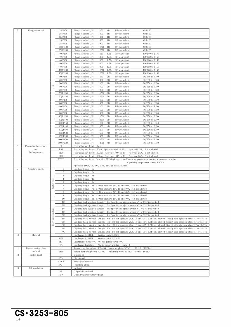
7 Flange standard
JPI
25JP150 Flange standard JPI 150 1B RF-equivalent Only E0
25JP300 Flange standard JPI 300 1B RF-equivalent Only E0
25JP400 Flange standard JPI 400 1B RF-equivalent Only E0
25JP600 Flange standard JPI 600 1B RF-equivalent Only E0
25JP900 Flange standard JPI 900 1B RF-equivalent Only E0
25JP1500 Flange standard JPI 1500 1B RF-equivalent Only E0
25JP2500 Flange standard JPI 2500 1B RF-equivalent Only E0
40JP150 Flange standard JPI 150 1.5B RF-equivalent E0/E50 to E150
40JP300 Flange standard JPI 300 1.5B RF-equivalent E0/E50 to E150
40JP400 Flange standard JPI 400 1.5B RF-equivalent E0/E50 to E150
40JP600 Flange standard JPI 600 1.5B RF-equivalent E0/E50 to E150
40JP900 Flange standard JPI 900 1.5B RF-equivalent E0/E50 to E150
40JP1500 Flange standard JPI 1500 1.5B RF-equivalent E0/E50 to E150
40JP2500 Flange standard JPI 2500 1.5B RF-equivalent E0/E50 to E150
50JP150 Flange standard JPI 150 2B RF-equivalent E0/E50 to E150
50JP300 Flange standard JPI 300 2B RF-equivalent E0/E50 to E150
50JP400 Flange standard JPI 400 2B RF-equivalent E0/E50 to E150
50JP600 Flange standard JPI 600 2B RF-equivalent E0/E50 to E150
50JP900 Flange standard JPI 900 2B RF-equivalent E0/E50 to E150
50JP1500 Flange standard JPI 1500 2B RF-equivalent E0/E50 to E150
50JP2500 Flange standard JPI 2500 2B RF-equivalent E0/E50 to E150
80JP150 Flange standard JPI 150 3B RF-equivalent E0/E50 to E150
80JP300 Flange standard JPI 300 3B RF-equivalent E0/E50 to E150
80JP400 Flange standard JPI 400 3B RF-equivalent E0/E50 to E150
80JP600 Flange standard JPI 600 3B RF-equivalent E0/E50 to E150
80JP900 Flange standard JPI 900 3B RF-equivalent E0/E50 to E150
80JP1500 Flange standard JPI 1500 3B RF-equivalent E0/E50 to E150
80JP2500 Flange standard JPI 2500 3B RF-equivalent E0/E50 to E150
100JP150 Flange standard JPI 150 4B RF-equivalent E0/E50 to E150
100JP300 Flange standard JPI 300 4B RF-equivalent E0/E50 to E150
100JP400 Flange standard JPI 400 4B RF-equivalent E0/E50 to E150
100JP600 Flange standard JPI 600 4B RF-equivalent E0/E50 to E150
100JP900 Flange standard JPI 900 4B RF-equivalent E0/E50 to E150
100JP1500 Flange standard JPI 1500 4B RF-equivalent E0/E50 to E150
100JP2500 Flange standard JPI 2500 4B RF-equivalent E0/E50 to E150
8 Protruding flange part
and
diaphragm cover
E0 Protruding part length 0mm
E50 Protruding part length 50mm Aperture 100A or 4B Aperture 25A, 1B not allowed.
E100 Protruding part length 100mm Aperture 100A or 4B Aperture 25A, 1B not allowed.
E150 Protruding part length 150mm Aperture 100A or 4B Aperture 25A, 1B not allowed.
E0TDS Protruding part length 0mm with FEP diaphragm cover(Operating pressure: atmospheric pressure or higher,
Operating temperature -10 to 120℃)
Apertures 100A, 4B, 40A, 1.5B, 25A, 1B is not allowed.
9 Capillary length
Waf
er t
ype
1 Capillary length 1m
2 Capillary length 2m
3
Capillary length 3m
4 Capillary length 4m
5 Capillary length 5m
6 Capillary length 6m E>0 for aperture 25A, 1B and 40A, 1.5B not allowed.
7 Capillary length 7m E>0 for aperture 25A, 1B and 40A, 1.5B not allowed.
8 Capillary length 8m E>0 for aperture 25A, 1B and 40A, 1.5B not allowed.
9 Capillary length 9m E>0 for aperture 25A, 1B and 40A, 1.5B not allowed.
10 Capillary length 10m E>0 for aperture 25A, 1B and 40A, 1.5B not allowed.
Bac
K e
ject
ion
type
1U Capillary back ejection Length 1m Specify side ejection when VT or SVT is specified.
2U Capillary back ejection Length 2m Specify side ejection when VT or SVT is specified.
3U Capillary back ejection Length 3m Specify side ejection when VT or SVT is specified.
4U Capillary back ejection Length 4m Specify side ejection when VT or SVT is specified.
5U Capillary back ejection Length 5m Specify side ejection when VT or SVT is specified.
6U Capillary back ejection Length 6m E>0 for aperture 25A, 1B and 40A, 1.5B not allowed, Specify side ejection when VT or SVT is
specified. 7U Capillary back ejection Length 7m E>0 for aperture 25A, 1B and 40A, 1.5B not allowed, Specify side ejection when VT or SVT is
specified. 8U Capillary back ejection Length 8m E>0 for aperture 25A, 1B and 40A, 1.5B not allowed, Specify side ejection when VT or SVT is
specified. 9U Capillary back ejection Length 9m E>0 for aperture 25A, 1B and 40A, 1.5B not allowed, Specify side ejection when VT or SVT is
specified. 10U Capillary back ejection Length 10m E>0 for aperture 25A, 1B and 40A, 1.5B not allowed, Specify side ejection when VT or SVT is
specified. 10 Material - Diaphragm:SUS316L Wetted parts:SUS316
316L Diaphragm:SUS316L Wetted parts:SUS316L
HC Diaphragm:Hastelloy C Wetted parts:Hastelloy C
TA Diaphragm:Tantalum Wettd parts:Tantalum Only E0
11 Bolt/mounting plate
material
- Sensor body flange bolt: SCM435 Mounting plate: SPCC U-bolt: SUS304
S630 Sensor body flange bolt: SUS630 Mounting plate: SUS304 U-bolt: SUS304
12 Sealed liquid - Silicone oil
FO Fluorine oil
100CS Sanitary Silicone oil
PG Propylene glycol
13 Oil prohibition - No finish
NL Oil prohibitive finish
NLW Oil and water prohibitive finish

15
CS・3253-805
14
Wetted parts conditions - Standard
HT High temperature type Wetted parts temperature —10 to 310℃ * Sealed liquid code cannot be specified.
LT Low temperature type Wetted parts temperature —70 to 60℃ * Sealed liquid code cannot be specified.
V Vacuum type Wetted parts temperature —20 to 180℃ * Sealed liquid code cannot be specified.
WVT Wafer type high temperature vacuum type. Wetted parts temperature —10 to 310℃ * Sealsed liquid code cannot be specified.
Only side ejection is available for capillary.
VT High temperature vacuum type Wetted parts temperature —10 to 310℃ * Sealed liquid code cannot be specified.
Only flange size E0 for 80A and 100A are supported, Only bacK ejection is available for capillary.
SVT High temperature / high vacuum type
Wetted parts temperature 10 to 310℃
Operable vacuum 0.0133KPa abs.
* Sealed liquid code cannot be specified.
Only flange sizes E0 of 80A and 100A are supported. The material of the diaphragm is limited to Hastelloy C.
Only backside extraction of capillary is supported.
Example of Code description:EPR-N8S-G20-XC-M-80J10-E0-5
HCS-E2205
●HART® is a registerd trademark of the Field Comm Group.
●Please read the “Instruction Manual” carefully before use.
●Appearance and specifications are subject to change partially for improvement.