intelligent software division -...
TRANSCRIPT

I N T E L L I G E N T S O F T W A R E D I V I S I O N
I / A S E R I E S
H E A D B O X C O N T R O L
M A I N T E N A N C E G U I D E

Foxboro, Fox and I/A Series are registered trademarks of The Foxboro Company.
The Intelligent Automation People is a service mark of The Foxboro Company.
Siebe is a registered trademark of Siebe, plc.
Copyright 1999 by The Foxboro Company
All rights reserved
SOFTWARE LICENSE AND COPYRIGHT INFORMATION
Before using the Foxboro supplied software supported by this Foxboro documentation, you should read and understand the following information concerning copyrighted software.
1. The license provisions in the Foxboro Software License for your system govern your obligations and usage rights to the software described in this documentation. If any portion of those license provisions is violated, The Foxboro Company will no longer provide you with support services and assumes no further responsibilities for your system or its operation.
2. All software issued by The Foxboro Company, and copies of the software that you are specifically permitted to make, are protected in accordance with Federal copyright laws. It is illegal to make any copies of any software media provided to you by The Foxboro Company for any purpose other than those permitted in the Foxboro Software License.
Page iii
Contents
Headbox Control Maintenance Guide
Overview ...................................................................................... 1
Software Architecture ................................................................ 3
Jet/Wire Calculation ..................................................................... 5
Dryline Calculation ....................................................................... 5
Headbox Level .............................................................................. 8
Settings......................................................................................... 9
Historian Variables................................................................... 12
Troubleshooting Guide............................................................. 13
Appendix: Rush-Drag Conversion .......................................... 16

Page iv Headbox Control Maintenance Guide
PrefaceThe Foxboro Headbox Control package improves the performance of your paper machine. It regulates headbox functions to assure a uniformly high quality of paper at the reel.
AudiencePeople who monitor and operate paper machines under The Foxboro Company I/A Series distributed control system should be familiar with the contents of this guide.
Related DocumentHeadbox Control Operator Guide (ISD0014TE)
System RequirementsThe hardware and software requirements for the Headbox Control package are:
• 5% of a CP-40 for supervisory control
• Minimum AW51-B workstation, with a minimum of 96 MB of memory, 2.1 GB hard drive and Historian 1000
• I/A Series software, Release 4.3 or later
• WP51 display stations

Overview Page 1
OverviewThe Headbox Control package assures a well-regulated flow through the headbox (Figure 1). The Headbox Control Maintenance Guide outlines control strategies and tuning procedures for the package. It assumes familiarity with the Foxboro I/A Series distributed control system. Within this operating environment, the maintenance guide discusses these topics:
• Data flow for the headbox control loops
• Calculation of the total head setpoint
• Calculation of the slice position setpoint
• Regulation of the pond level
• Gain settings for dryline control
• Historian variables
• Basic troubleshooting procedures
Figure 1 Hydraulic Headbox
Note The Headbox Control package is based on Jet/Wire calculations, but the headbox compound contains the blocks needed to calculate Rush-Drag. To convert the Headbox Control package to Rush-Drag, see the Appendix: Rush-Drag Conversion on page 16.
Air Pad
Pond
DrylineSlice
SliceOpening
Jet
Variable SpeedFan Pump
HeadboxLevel
Wire
CompressedAir
Vent
Flow

Page 2 Headbox Control Maintenance Guide
The application includes a headbox control simulator to train machine operators and to check out the Headbox Control package. The simulator uses the MD Control Summary display (Figure 2) documented in the Headbox Control Operator Guide (ISD0014TE). Because the application has only one set of output blocks, you cannot run the simulation and the application simultaneously. Therefore, use the simulator during factory testing and operator training, before you connect the blocks to the process. After you connect the blocks to the process, the controls on the operator display are all operational.
Note The names of supervisory loops in the MD Control Summary display use gray lettering, and the names of regulatory loops use white lettering. The names of the regulatory control loops at your site may not be the same as those shown in Figure 2.
Figure 2 Machine-Direction Control Summary Display
Note Block and parameter names in this guide assume a Headbox Control package installed on Paper Machine 1. The headbox control compound on the first machine is named P1_HEADBOX. P4_HEADBOX indicates a Headbox Control package running on Paper Machine 4.

Software Architecture Page 3
Software ArchitectureThe Headbox Control package regulates total head, the vertical slice opening, and several other variables connected with the operation of the headbox. The entire control package resides in the control processor, in the compound P1_HEADBOX. Figure 3 on page 6 and Figure 4 on page 7 illustrate the software architecture and control strategies used in the package. They diagram the flow of data among the various blocks in P1_HEADBOX. Several features of the package are worth noting:
• The jet/wire setpoint determines the relationship between jet velocity and wire speed. If the ratio is greater than 1, the velocity of the stock as it leaves the headbox (jet velocity) is greater than the speed of the wire. If the ratio is less than 1, the velocity of the stock as it leaves the headbox is less than the speed of the wire.
• The jet/wire calculation regulates total head to assure that the ratio of jet velocity to wire speed is constant.
• The package sends a total head setpoint to the total head controller. The total head controller typically regulates the output to the fan pump to achieve the setpoint.
• The dryline calculation regulates the slice position to maintain the position of the dryline.
• The package sends a slice position setpoint to the slice position controller. The slice position controller opens and closes the slice to achieve the setpoint.
The Headbox Control package contains five control loops:
• Jet/Wire Ratio
• Total Head
• Dryline
• Slice
• Headbox Level

Page 4 Headbox Control Maintenance Guide
Table 1 contains descriptive information for each of these control loops. The name of the loop appears in the first column of the table. The Loop Type is either supervisory or regulatory (see the Headbox Control Operator Guide for a comparison of these two loop types). The Compound:Block Name gives the name of the loop in the I/A Series control database. Typical Units of Measurement refers to the values in the Measurement, Setpoint, and Output columns of the Machine-Direction Control Summary display (Figure 2 on page 2).
Note Regulatory control configurations vary substantially from site to site. The regulatory control loops at your plant may have block names that differ from those listed in Table 1, and these blocks may reside in different compounds. In some setups one or more regulatory loops may be absent altogether. Regulatory controls are included for reference and completeness, and to ensure the simulator operates properly.
Table 1 Control Loop Descriptions
Loop Name Loop Type Compound:Block NameTypical Units of Measurement
Meas/Spt Output
Jet/Wire Ratio Supervisory P1_HEADBOX:JETWIRECALC N/A N/A
Total Head Regulatory P1_HEADBOX:TOTALHEAD Pressure in inches of water
% output (fan pump)
Dryline Supervisory P1_HEADBOX:DRYLINECALC N/A N/A
Slice Regulatory P1_HEADBOX:SLICEVERT Inches N/A
Headbox Level Regulatory P1_HEADBOX:PONDLEVEL % level (headbox)
% output (air pad/vent valve)

Jet/Wire Calculation Page 5
Jet/Wire CalculationThe jet/wire calculation uses two equations. The first one relates the target jet velocity, V, to the operator-entered jet/wire ratio setpoint and to the wire speed:
V = (Ratio Setpoint) (Wire Speed)
If the ratio setpoint is 1.1, for example, the target jet velocity is 10% higher than the wire speed.
The second equation relates the target jet velocity, V, to the target total head, h:
where gc is the gravity constant. If you solve this equation for total head, you have:
And:
The block P1_HEADBOX:JETWIRECALC calculates both the target jet velocity and the target total head. Figure 3 on page 6 illustrates the flow of data related to this block.
Dryline CalculationThe dryline position varies according to the volume of water that passes through the vertical slice opening. When Dryline is in Automatic and the stock gain or speed gain setting is not zero, Dryline updates the setpoint of the slice position controller. Then the vertical slice opening adjusts to changes in the thick stock flow rate or to changes in the wire speed. As the thick stock flow rate decreases or the wire speed increases, the slice closes to prevent the dryline from moving forward. Figure 4 on page 7 illustrates the flow of data related to the dryline calculation. For an explanation of the equation used in this calculation, see Gain Settings on page 11.
V 2gch=
V2
2gch=
hV
2
2gc---------=

Page 6 Headbox Control Maintenance Guide
Figure 3 Jet/Wire Calculation
Wire Speed
Headbox Control Package
Controllers and Equipment
Total Head RI01
RI02
RO03
RO02
Total Head Controller
RO04
ActualJet/Wire Ratio
RO01
JETWIRECALC(Jet/Wire Calculation)
Total HeadSetpoint
Fan Pump Speed
Actual
Jet Velocity
Jet/Wire Setpoint(Operator Entered)
To DrylineCalculation

Dryline Calculation Page 7
Figure 4 Dryline Calculation
DrylinePosition
Wire Speed
Slice Width
Slice Opening
Stock Flow
Slice Position
Slice Position
Controller
Headbox Control Package
Controllers and Equipment
Actual Jet Velocity
Theoretical Headbox
Consistency
Headbox Flow
RI0001
RI0007
RI0003
RI0002
RI0005
DRYLINECALC
RO0001
Vertical Slice Opening
Desired
(Dryline Calculation)
RO0001
RO0002
Setpoint
From Jet/WireCalculation

Page 8 Headbox Control Maintenance Guide
Headbox LevelHeadbox Level is a regulatory control loop. It maintains an air pad in the headbox that regulates the pond level (Figure 5). An air compressor and a dual-valve system at the top of the headbox maintain the air pressure on the surface of the water. To increase the air pad pressure, the compressed air valve opens and the vent valve closes. To reduce the air pad pressure, the compressed air valve closes and the vent valve opens. As flow through the headbox fluctuates, the air pad serves as a cushion that helps to control the headbox level.
Figure 5 Headbox Level
Note Headbox Level is a regulatory controller that may not be required for your system. Please see the note on page 4.
Air Pad
Pond
Fan Pump
Headbox Level
CompressedAir
Vent
Flow through the headbox

Settings Page 9
SettingsThis section contains general definitions and procedures related to the MD Headbox Tuning Parameter table (Figure 6). It explains how to change a setting, and describes the gain settings used to tune the Dryline control loop. The table arranges information for these settings in five columns:
• Description – The name of the parameter.
• Block and Parameter – The parameter designation in the I/A Series control database.
• Units – The units of measurement for the parameter.
• Nominal Value – Factory settings intended for use as a reference during maintenance procedures.
• Actual Value – The actual value of the parameter as set by a process control engineer.
Figure 6 Headbox Tuning Parameter Table

Page 10 Headbox Control Maintenance Guide
Note The numbers in the Nominal Value column are factory settings or reference values. Use them if necessary as a starting point during machine maintenance or software maintenance. The numbers in the Actual Value column are for illustration only. Determine the actual values for your machine independently.
Figure 6 on page 9 contains four settings for the Headbox Control package:
• Dryline stock gain
• Dryline speed gain
• Total head setpoint rate of change limit
• Vertical slice setpoint rate of change limit
How to Change a SettingFigure 6 on page 9 contains the tuning parameters relevant to the Headbox Control package. To change the value of a tuning parameter:
1. Move the cursor to the setting in the Actual Value column that you want to change. A small rectangle appears around the setting.
2. Click the setting. A blue data entry field appears.
3. Type the new setting and press Enter.
Note After a successful tuning operation, perform an Upload and Checkpoint to ensure the tuning parameters are saved permanently. As a precaution, do a SaveAll as well.

Settings Page 11
Gain SettingsThe gain settings for dryline control should reflect the operating characteristics of your machine. The discussion below uses examples based on the settings in the Actual Value column of Figure 6 on page 9. The operating characteristics and particular settings for your machine will differ.
The Dryline control loop uses the following equation to calculate a new slice position:
(Change in Thick Stock Flow) (Thick Stock Flow Gain) +
(Change in Machine Speed) (Speed Gain) +
Current Slice Position = New Slice Position
For example, let the thick stock flow rate change from 2,000 gpm to 2,020 gpm. The change in the thick stock flow rate is 20 gallons per minute. Let the stock flow gain equal 0.0000. (As a result, the term drops out of the dryline calculation.) If the machine speed increases from 1,700 fpm to 1,750 fpm, the change in machine speed is 50 feet per minute. Let the speed gain equal –0.0005. Lastly, let the current height of the slice equal 1.5 inches. These figures yield the following calculation:
(2,000 gpm) (0.0000 in./gpm) +
(50 fpm) (–0.0005 in./fpm) + 1.5 in.=
0.00 + (–0.025 in.) + 1.5 in.= 1.475 inches
The new vertical slice opening is 1.475 inches, or 0.025 inches less than before. If the machine speed increases, total head increases to maintain a constant jet/wire ratio. As a result, more water flows onto the wire, and the dryline begins to move forward. To restrict the flow, Dryline control lowers the slice. If in this example the machine speed decreases 50 fpm, the vertical slice opens 0.025 inches.
Rate of Change LimitsThe rate of change limits in the Tuning Parameter table keep the total head and vertical slice setpoints from changing too rapidly. The total head rate of change limit in Figure 6 on page 9 is 0.1 inches of water per second. The vertical slice setpoint rate of change limit is 0.01 inches per second. Set these limits low enough that when a speed change or a grade change occurs, the setpoints do not change so rapidly as to upset the process.
Page 12 Headbox Control Maintenance Guide
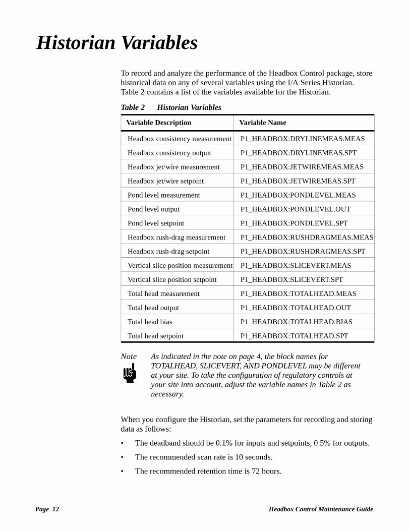
Historian VariablesTo record and analyze the performance of the Headbox Control package, store historical data on any of several variables using the I/A Series Historian. Table 2 contains a list of the variables available for the Historian.
Note As indicated in the note on page 4, the block names for TOTALHEAD, SLICEVERT, AND PONDLEVEL may be different at your site. To take the configuration of regulatory controls at your site into account, adjust the variable names in Table 2 as necessary.
When you configure the Historian, set the parameters for recording and storing data as follows:
• The deadband should be 0.1% for inputs and setpoints, 0.5% for outputs.
• The recommended scan rate is 10 seconds.
• The recommended retention time is 72 hours.
Table 2 Historian Variables
Variable Description Variable Name
Headbox consistency measurement P1_HEADBOX:DRYLINEMEAS.MEAS
Headbox consistency output P1_HEADBOX:DRYLINEMEAS.SPT
Headbox jet/wire measurement P1_HEADBOX:JETWIREMEAS.MEAS
Headbox jet/wire setpoint P1_HEADBOX:JETWIREMEAS.SPT
Pond level measurement P1_HEADBOX:PONDLEVEL.MEAS
Pond level output P1_HEADBOX:PONDLEVEL.OUT
Pond level setpoint P1_HEADBOX:PONDLEVEL.SPT
Headbox rush-drag measurement P1_HEADBOX:RUSHDRAGMEAS.MEAS
Headbox rush-drag setpoint P1_HEADBOX:RUSHDRAGMEAS.SPT
Vertical slice position measurement P1_HEADBOX:SLICEVERT.MEAS
Vertical slice position setpoint P1_HEADBOX:SLICEVERT.SPT
Total head measurement P1_HEADBOX:TOTALHEAD.MEAS
Total head output P1_HEADBOX:TOTALHEAD.OUT
Total head bias P1_HEADBOX:TOTALHEAD.BIAS
Total head setpoint P1_HEADBOX:TOTALHEAD.SPT

Troubleshooting Guide Page 13
Troubleshooting GuideWhen both Jet/Wire Ratio and Dryline are in Automatic and the control system has no fault conditions, the status indicators in the Headbox Control Help overlay are all green (see the right side of Figure 7). To bring up the Help overlay, click Headbox Control Help in either the MD Control Summary display (Figure 2 on page 2) or the Headbox Detail display (see the left side of Figure 7).
Figure 7 Headbox Control Help Overlay
Status Indicators
Mode Indicator

Page 14 Headbox Control Maintenance Guide
Specific fault conditions in the control system cause a status indicator on the Help overlay to become gray. See the Headbox Control Operator Guide (ISD0014TE) for a description of these fault conditions. Table 3 contains a list of parameters and data points to check in connection with each of the status indicators.
Note As you locate the parameters listed in Table 3, recall that the block names for regulatory loops may differ at your site. See the note on page 4.
Table 4 shows how P1_HEADBOX:JETWIRESTAT.PAKCRB and P1_HEADBOX:DRYLINESTAT.PAKCRB combine inputs from the operator display and from JETWIRECALC or DRYLINECALC to determine the control status of the supervisory loops, Jet/Wire Ratio and Dryline.
Table 4 PAKCRB Logic for Jet/Wire Ratio and Dryline
Table 3 Troubleshooting Checks
Status Indicators Description of Problem Parameters to Check
Op Request Headbox Jet/Wire
Jet/ Wire Ratio does not go into Automatic when requested.
P1_HEADBOX:JETWIRECALC.BI01P1_HEADBOX:JETWIRESTAT.PAKCRB
Total Head in Cascade Total Head is not in Cascade when it ought to be.
P1_HEADBOX:TOTALHEAD.LR
Op Request Dryline Dryline does not go into Automatic when requested.
P1_HEADBOX:DRYLINECALC.BI0001P1_HEADBOX:DRYLINESTAT.PAKCRB
Slice in Cascade Slice is not in Cascade when it ought to be.
P1_HEADBOX:SLICEVERT.LR
Auto/Manual Request from Operator
Status Bit from JETWIRECALC or DRYLINECALC
Control Status of Jet/Wire Ratio or Dryline
Description
0 = Manual 0 = Good Off Operator requests manual. Equipment and data status immaterial.
0 = Manual 1 = Bad Off Operator requests manual. Equipment and data status immaterial.
1 = Automatic 0 = Good Auto Operator requests Automatic. Equipment and data status good.
1 = Automatic 1 = Bad Susp Operator requests Automatic. Equipment or data status bad.

Troubleshooting Guide Page 15
Table 5 shows how to interpret the Boolean status parameters in P1_HEADBOX.
Total Head in CascadeThe output parameter for this indicator, P1_HEADBOX:TOTALHEAD.LR, is the Local/Remote switch of the fan pump controller. When the fan pump controller is under local control, it cannot be in Cascade. The actual Compound:Block.Parameter designation of P1_HEADBOX:TOTALHEAD.LR depends on the names and configuration of regulatory controllers at your site.
Jet/Wire Ratio (Operator Request)Op Request Headbox Jet/Wire shows whether the operator has put Jet/Wire Ratio in Automatic from the MD Control Summary display. If the operator has requested Automatic and the control loop remains suspended, the status bit from JETWIRECALC must be bad (see row four in Table 4). Table 4 shows how P1_HEADBOX:JETWIRESTAT.PAKCRB combines two Boolean output bits into the three possible control statuses: Automatic, Off, and Suspend. Check the output bits listed in row one of Table 3 when Jet/Wire Ratio should be in Automatic but is not.
Slice in CascadeThe output parameter for this indicator, P1_HEADBOX:SLICEVERT.LR, is the Local/Remote switch of the slice controller. When the slice controller is under local control, it cannot be in Cascade. The actual Compound:Block.Parameter designation of P1_HEADBOX:SLICEVERT.LR depends on the names and configuration of regulatory controllers at your site.
Dryline (Operator Request)Op Request Dryline shows whether the operator has put Dryline in Automatic from the MD Control Summary display. If the operator has requested Automatic and the control loop remains suspended, the status bit from DRYLINECALC must be bad (see row four in Table 4). Table 4 shows how P1_HEADBOX:DRYLINESTAT.PAKCRB combines two Boolean output bits into the three possible control statuses: Automatic, Off, and Suspend. Check the output bits listed in row three of Table 3 when Dryline should be in Automatic but is not.
Table 5 Headbox Status Indicators
Status Indicator Key Parameter Interpretation of Boolean Variable
Total Head in Cascade
P1_HEADBOX:TOTALHEAD.INITO True = Bad (Total Head not in Cascade)
Slice in Cascade P1_HEADBOX:SLICEVERT.INITO True = Bad (Slice not in Cascade)

Page 16 Headbox Control Maintenance Guide
Appendix: Rush-Drag ConversionTo convert the Headbox Control package from Jet/Wire to Rush-Drag, execute the following steps:
1. Make a backup copy of all the displays in the package.
2. Change directory to /opt/pm1/mdcntl .
3. Type d_edit -c,JETWIRE,RUSHDRAG, MD_SUM HD_BOX (Enter this command twice).
4. Type d_edit -T,Jet/Wire Ratio,Rush Drag, MD_SUM HD_BOX .
5. Change directory to /opt/pm1/ovl .
6. Type d_edit -c,JETWIRE,RUSHDRAG, hdbxhelp .
7. Type d_edit -T,Jet/Wire Ratio,Rush Drag, hdbxhelp .
8. In the Integrated Control Configurator, disconnect P1_HEADBOX:TOTALHEAD.RSP from JETWIRELIM and connect it to RUSHDRAGLIM.


The Intelligent Automation People
The Foxboro CompanyFoxboro, MA 02035-2099
Telephone (508) 543-8750(888) 369-2676
Facsimile (508) 549-6750
PUB
Printed in U.S.A.
Headquarters, North America, 1-800-521-0451Latin America. +508-543-8750Europe, +49-711-502-0Mideast (Saudi Arabia), 966-3-859-1111, Ext. 1501Mideast (Dubai), 971-4-319-050Far East, +65-265-7155
The Foxboro Company 1999All rights reserved.
®
A Siebe Group Company
ISD0015TE