intelligent voltage stabilizer for electrical power
TRANSCRIPT

Intelligent Voltage Stabilizer for Electrical
Power Distribution Systems
Samir Ahmad Jabr
Lecturer at College of Science and Technology – Khan Yunis
Abstract
Real-life applications of intelligent systems that use neural networks require a
high degree of success, usability and reliability. Power systems applications can
benefit from such intelligent systems; particularly for voltage stabilization.
Voltage instability in power distribution systems could lead to voltage collapse
and thus power blackouts.
This paper introduces an intelligent voltage stabilizer (IVS) with two phases.
The first phase is an intelligent detection system which uses a back propagation
learning algorithm neural network that detects instability or overload of power
distribution systems (PDS), thus providing a faster instability detection system
that simulates a trained operator controlling and monitoring the 3-phase voltage
output of the assumed PDS. The decision of the intelligent system is one of
three: stable, unstable, or overload system. The novelty of our work is the use of
voltage output images as the input patterns to the neural network for training and
generalizing purposes. Experimental results suggest that our method performs
well and provides a fast and efficient system for voltage instability detection.

The second phase is the voltage stabilizer that uses the decision of the first phase
with two branches. The first is performing quick steps to clean the voltage drop
which results from the overload if it is detected, while the second is stability
restoration of the PDS if instability is detected. The IVS will work concurrently
with SCADA systems, in grids that use it to supervise and control power flow,
to help in taking quick arrangement to prevent voltage collapse in PDS.
Additionally, the proposed intelligent voltage stabilizer could be used with other
control systems as a temporary solution for preventing voltage collapse.
Keywords: Neural Networks, Intelligent Systems, Image Processing, Voltage
Instability Detection, Power Distribution Systems, Voltage Stabilizer.

الكهربائية مثبت الجهد الذكي لأنظمة توزيع القدرة
سمير أحد جبر خان يونس –محاضر في كمية العموم والتكنولوجيا
الممخص:التطبيقات الواقعية للأنظمة الذكية التي تستعمل الشبكات العصبية الذكية تتطمب درجة عالية من
النجاح والاستخدام والثقة، وقد تستفيد تطبيقات الأنظمة الكيربائية من مثل ىذه الأنظمة الذكية خاصة
الجيد في محطات توزيع القدرة إلى انييار الجيد ؛ حيث يمكن أن تؤدي عدم استقرارلاستقرار الجيد
وبالتالي إلى انقطاع الطاقة الكيربائية.
وىو مكون من جزأين، الجزء الأول ىو مثبت الجيد الذكي لأنظمة توزيع القدرةتقدم ورقة العمل ىذه
تقرارد عكسي مدربة تكتشف عدم اسنظام المكتشف الذكي الذي يستخدم شبكة عصبية ذكية ذات تولي
الجيد، حيث يتم توفر اكتشاف سريع لعدم استقرار الجيد أو زيادة الحمل في محطات توزيع القدرة والتي
الثلاثة في نظام محاكاة عمى الحاسوب لنظام توليد وتوزيع طوارتدريب ىذه الشبكة عمى صور لمجيد للأ
ع، وينتج عن ىذا النظام الذكي أحد القدرة والتي تقمد نظام كيربائي فعمي ثلاثي الطور في محطات التوزي
ثلاثة احتمالات، ىي: نظام مستقر، أو نظام غير مستقر أو نظام محمل بفرط. والحداثة في ىذه الورقة
أو النظام الفعمي كمداخل لمشبكة العصبية الذكية المحاكيىي استعمال صور الجيود الثلاثة لمنظام
الجيد أو عدميا، وقد دلت النتائج العممية عمى قدرة ىذه لاحقاً لمحسم في مسألة استقرار لمتدريب ثم

الجيد في محطات توزيع القدرة. أما الجزء الثاني من مثبت ى الاكتشاف المبكر لعدم استقرارالشبكة عم
الجيد الذكي فيستخدم نتائج نظام الاكتشاف الذكي لاتخاذ خطوات من شأنيا عدم ىبوط الجيد عند
. يمكن ليذا الاستقرارالجيد عند اكتشاف عدم الحمل أو المحافظة عمى استقرار اكتشاف زيادة مفرطة في
النظام مساعدة نظام التحكم والمراقبة واستخلاص البيانات المعروف باسم )سكادا( في شبكات القوى
ارالكيربائية التي تستخدمو من أجل القيام بخطوات أسرع لمتخمص من النتائج المدمرة من عدم استقر
جيد، كما يمكن استخدامو كبديل مؤقت لنظام سكادا بالإضافة إلى أنظمة التحكم الأخرى الموجودة في ال
الشبكة الكيربائية التي لا تستخدم نظام سكادا لممراقبة والتحكم.
الشبكات العصبية، الأنظمة الذكية، معالجة الصور، اكتشاف عدم استقرار الجيد، كممات افتتاحية:
.مثبت الجيد، القدرةأنظمة توزيع

I. INTRODUCTION
Voltage instability analysis is concerned with the inability of assessing the
power system to maintain acceptable voltages at all system buses under normal
conditions and after being subjected to disturbances. A major factor contributing
to voltage instability is the voltage drop that occurs when active and reactive
power flow through inductive reactances of the transmission network. Voltage
stability is threatened when a disturbance increases the reactive power demand
beyond the sustainable capacity of the available reactive power resources.
The distribution feeders may become overloaded due to load growth,
difficulties with the distribution system operation and substation planning in
areas with high load density. Power occasionally fails when circuit breakers are
tripped; when over current relays are operated by a distribution system overload.
Excessive unbalance of the three-phase load may cause grounding relays to be
activated, causing frequent power cuts that seriously affect the quality of the
power supply.
Voltage collapses typically occurs on power systems which are heavily loaded,
faulted and/or have reactive power shortages. Voltage collapse is system
instability in that it involves many power system components and their variables
at once. Voltage collapse is typically associated with the reactive power
demands of loads not being met because of limitations on the production and
transmission of reactive power.

The implementation of neural networks for stabilizing power systems in
general has been recently suggested [1]–[5]. Research on different approaches
to the assessment and improvement of voltage stabilization in particular has
proposed different solutions to voltage instability using neural networks [6]–
[10]. However, none of the existing intelligent system solutions to detecting
voltage instability in power distribution systems addresses the possibility of
providing an artificial intelligent detector that simulates a human operator whose
task is to detect voltage instability via monitoring the voltage output.
Progress in the areas of communication and digital technology has increased
the amount of information available at supervisory control and data acquisition
(SCADA) systems [11],[12]. Although information is very useful, during events
that cause outages, the operator may be overwhelmed by the excessive number
of simultaneously operating alarms, which increases the time required for
identifying the main outage cause and to start the restoration process. Besides,
factors such as stress and inexperience can affect the operator’s performance;
thus, the availability of a tool to support the real-time decision-making process
is welcome.
The paper will introduce a new voltage stabilizer for power distribution
systems (PDS) based on artificial neural network (ANN) detection of instability
that works concurrently with SCADA systems to help preventing voltage
collapse in PDS.

The design of this voltage stabilizer has two phases. The first phase is an
intelligent system which uses a back propagation learning algorithm neural
network that detects instability or overload of PDS. The neural network will be
trained on patterns preprocessed from voltage images outputs in MATLAB
simulator for a suggested power system facing instability and overload
problems. Testing the neural network will be performed using voltage output
patterns that were not exposed to the ANN. The neural network is used in this
work to substitute the human monitor in the control center of the power system.
It also works as another support for decision to help preventing voltage
instability in case of late reaction from control center after a disturbance risk.
The second phase of the intelligent voltage stabilizer uses the output of the
first phase which is the ANN classifier. The proposed stabilizer has two
branches, one to solve the instantaneous voltage drop which result from the
overload state, and the other to solve transient voltage instability of the system.
After a while and when the system returns to stability the stabilizer will make
reverse procedures to return the control devices to its normal conditions.
MATLAB is used in programming the intelligent system which is a back
propagation learning algorithm neural network. In addition, it is used in
programing the second phase of the IVS while taking arrangements to restore
voltage stability.

II. INTELLIGENT SYSTEM DETECTION
A. Patterns Preparation
As lake of previous data for voltage instability or very loaded system data
from a real power system, a power system is proposed that is the BPA test case
study with some modification. It is then simulated using ready blocks in
powerlib in MATLAB. Fig. 1 shows the one-line diagram of the proposed power
system. Our concern is on the transient stability of one distribution power
substation. The voltages of substation 7 are taken as outputs of the circuit after
simulation. The intelligent voltage instability detection system has three possible
output classifications (Stable, Unstable or Overload). The image database has to
account for the three cases, which are obtained via simulation as follows:
Stable cases: small additional loads are added or subtracted from the
substation at different times to simulate normally loaded system which makes
the terminal voltage higher than 95% of the nominal voltage.
Unstable cases: ordinary faults are induced on the transmission grid of the
system or in the environment of the substation for a short time then recovered
and their effect is recorded or, alternatively, one of the generators is switched
off during simulation at different times.
Overload cases: large additional loads are added to the substation at different
times to force it to be overloaded and the terminal voltage is lowered to less than
95% of the nominal voltage [14],[15].

Fig. 1. Proposed Test Case Power System.
The patterns are extracted and saved as a feature vector. The procedure
includes saving three phases voltage graphs for every case as digital images with
a size of (540x800) pixels, then converting to gray and resizing to (400x202)
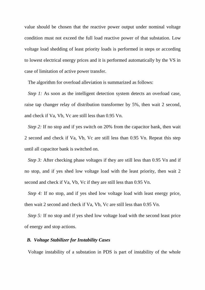
pixels. Fig. 2 shows examples of saved images. After that starting from column
2 to column 201 the pixel position where the first grey level discontinuity occurs
is found and the number of this row is saved in a vector. Fig. 3 shows example
of finding pixel position. This saved value represents the highest voltage value
at that column in that image. The process of recording the row numbers where
the highest voltage value occurs is repeated, thus yielding a feature vector with
200 values for each voltage output graph. As a result, each case is represented
by a pattern or feature vector with 600 values. The 600 values within each
pattern are normalized to values from “0” to “1” using division by 400 which is
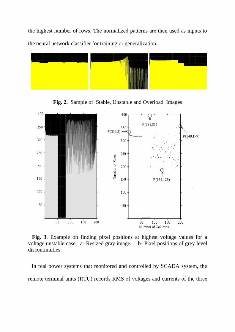
the highest number of rows. The normalized patterns are then used as inputs to
the neural network classifier for training or generalization.
Fig. 2. Sample of Stable, Unstable and Overload Images
Fig. 3. Example on finding pixel positions at highest voltage values for a
voltage unstable case, a- Resized gray image, b- Pixel positions of grey level
discontinuities
In real power systems that monitored and controlled by SCADA system, the
remote terminal units (RTU) records RMS of voltages and currents of the three

phases with respect to time as curves all the time including unusual events. Fig.
4 shows an example of voltage sag which may force the system to be overload.
The hypothesis which is presented within this paper suggests that these graphs
of unusual events during a year can be taken and sampled to a fixed number of
samples. Three phase voltage samples are normalized by division over the
highest value of recorded voltage and then vectorized to be used as pattern
inputs to the neural network classifier to train it for detecting events that may
happen in future.
Fig. 4. Example of Recorded Voltage Sag for the Three Phases [13]
B. ANN Design
The intelligent voltage instability detection system uses a neural network
based on the back propagation learning algorithm due to its implementation
simplicity, and the availability of sufficient database for training this supervised
learner. The neural network consists of an input layer with 600 neurons
receiving the normalized values in each pattern, one hidden layer with 28

neurons which assures meaningful training while keeping the time cost to a
minimum, and an output layer with 3 neurons representing the voltage output
classification of stable, unstable or overload. During the learning phase, the
learning coefficient and the momentum rate were adjusted during various
experiments in order to achieve the required minimum error value of 0.002
which was considered as sufficient for this application. Fig. 5 shows the
topology of this neural network.
Fig. 5. Artificial Neural Network Topology
C. Intelligent System Implementation Results
The neural network learnt and converged after 12165 iterations and within 16
minutes (963 seconds), whereas the running time for the generalized neural
network after training and using one forward pass was 0.02 seconds. Table I lists
the final parameters of the successfully trained neural network.
Voltage instability detection results using the training image set (10 stable

cases, 10 unstable cases, and 10 overload cases) yielded 100% recognition as
would be expected. The intelligent system implementation using the testing
image set (8 stable cases, 8 unstable cases, and 8 overload cases that were not
previously exposed to the neural network) yielded correct voltage output
classification of 23 cases, thus achieving a 95.83% correct detection rate.
Combining testing and training image sets, an overall recognition rate of 98.1%
has been achieved. Table II shows the intelligent voltage instability detection
results in details.
TABLE I: NEURAL NETWORK FINAL TRAINING PARAMETERS
Input Neurons 600
Hidden Neurons 28
Output Neurons 3
Learning Coefficient 0.001
Momentum Rate 0.33
Error 0.002
Iterations 12165
TABLE II: INTELLIGENT VOLTAGE INSTABILITY DETECTION RESULTS
Stable
Cases
Training 10/10 (100%)
Testing 7/8 (87.5%)
Unstable
Cases
Training 10/10 (100%)
Testing 8/8 (100%)
Overloads
Cases
Training 10/10 (100%)
Testing 8/8 (100%)
All
Cases
Training 30/30 (100%)
Testing 23/24 (95.8%)
III. PROPOSED VOLTAGE STABILIZER
As soon as the ANN detects overload case or unstable case, the proposed
voltage stabilizer (VS) begins its work. It has two branches; the first is to

enhance the voltage drop that results from overload if it is detected, and the
other to assess voltage stability if instability is detected. Fig. 6 shows the general
block diagram of the proposed VS.
Fig. 6. General Block Diagram of the Proposed Voltage Stabilizer
A. Overload Voltage Stabilizer
The procedures for alleviation overloads are summarized in raising relay tap
changer of distribution transformers 5% of nominal voltage, then inserting
external reactive power in steps (every step is 20% of capacitor value) by using
switching capacitor banks, and if necessary shedding low voltage loads with the
least priority. The first step witch is raising the tap changer relay will be of
course performed automatically by the transformer itself as soon as it measures
drop of voltage, but VS make insure that this step is performed. The second step
witch is inserting reactive power is achieved because the main reason of
overload is the shortage of reactive power that transferred to loads. Capacitor
value should be chosen that the reactive power output under nominal voltage
condition must not exceed the full load reactive power of that substation. Low
voltage load shedding of least priority loads is performed in steps or according
to lowest electrical energy prices and it is performed automatically by the VS in
case of limitation of active power transfer.
The algorithm for overload alleviation is summarized as follows:
Step 1: As soon as the intelligent detection system detects an overload case,
raise tap changer relay of distribution transformer by 5%, then wait 2 second,
and check if Va, Vb, Vc are still less than 0.95 Vn.
Step 2: If no stop and if yes switch on 20% from the capacitor bank, then wait
2 second and check if Va, Vb, Vc are still less than 0.95 Vn. Repeat this step
until all capacitor bank is switched on.
Step 3: After checking phase voltages if they are still less than 0.95 Vn and if
no stop, and if yes shed low voltage load with the least priority, then wait 2
second and check if Va, Vb, Vc if they are still less than 0.95 Vn.
Step 4: If no stop, and if yes shed low voltage load with least energy price,
then wait 2 second and check if Va, Vb, Vc are still less than 0.95 Vn.
Step 5: If no stop and if yes shed low voltage load with the second least price
of energy and stop actions.
B. Voltage Stabilizer for Instability Cases
Voltage instability of a substation in PDS is part of instability of the whole

power system. It is caused due to faults or disturbances in its environment or due
to instability of the whole power system. Procedures to restore stability of the
PDS substation will be effective if the disturbances are in its environment,
otherwise procedures from all PDS substations with coordination of the whole
system must arise to restore stability. Local voltage stabilizer can’t distinguish
the cause of instability, as a results its actions to restore stability may not be
effective unless it comes in comprehensive of all PDS substations and other
parts of the system.
In this proposed stabilizer the first action is shedding part of instability
situations switching capacitor bank may not achieve the hoped performance
because the impact of their operation may be negative. Actions of the proposed
stabilizer are dependent on frequency which influence the generator’s rotor
speed. If the frequency (rotor speed) is increasing after a disturbance, then load
shedding will affect inversely and the rotor will accelerates which finally
destroy the generator. In the contrary, if the power system looses one or more
generation stations, then it might force other generators in neighbors to switch
off. As a result proper load shedding will decrease loading point which returns
the system to a new stable point on the upper part of the p-v curves.
The algorithm for stability assessment is summarized as follows noting that
the following numbers could be changed according to the power system:
Step 1: As soon as the intelligent detection system detects an instable case,
redispatch generators and shed one fourth of loads approximately. Wait 0.1
second then shed another fourth of loads approximately then another wait 0.1
second and shed another fourth of loads approximately.
Step 2: Wait 0.5 second then read Va, Vb, Vc and the frequency F, then wait
another 0.5 second then read Va, Vb, Vc and F again.
Step 3: Check if F is decreasing or increasing, and check if Va, Vb and Vc are
decreasing or increasing. There are three possibilities.
Step 4: If F is decreasing and the voltages are increasing, or if F is increasing
and the voltages are increasing or some of them is decreasing and the others are
increasing just redispatch generators then switch on the shed loads and stop
actions (because in case of increasing F shedding loads will not achieve stability
and it will be considered as rotor angle instability or frequency instability. In this
case, the automatic generator control or excitation system will react to assess
stability).
Step 5: If F is decreasing and Va, Vb and Vc are decreasing, wait few (3-5)
seconds then read them again. Check if F is increasing and Va, Vb and Vc are
decreasing or stay in the same level. If the answer is yes it means that stability is
achieved. Wait few (3-5) seconds then switch on the last shed loads. But, if the
answer is F is still decreasing, redispatch generators and stop actions.
IV. SIMULATION RESULTS
The proposed voltage stabilizer is tested for one overload case and one unstable
case from which that detected by the intelligent detection system.

A. Simulation Results of the Overload Case
In this case the line to neutral substation bus voltage was 0.768 p.u. and after
using the VS it is raised to 0.986 p.u. within 14 seconds. Table III shows the
value of substation bus voltage after each step.
TABLE III: NUMERICAL OUTPUTS OF ACTIONS FROM VS FOR OVERLOAD CASE 1
Type of Stabilizer Action Bus Voltage (p.u.)
Raising Tap Changer of Transformer 5% 0.772
Switching 20% from Capacitor Bank 0.778
Switching 40% from Capacitor Bank 0.790
Switching 60% from Capacitor Bank 0.807
Switching 80% from Capacitor Bank 0.834
Switching 100% from Capacitor Bank 0.857
Shedding LV load with the Least Priority 0.986
B. Simulation Results of the Unstable Cases
In this case, generator 1 is switched off after 8 seconds from start. The other
generators couldn’t deliver the needed power for the system as a result they
forced to collapse and the system goes to blackout. As soon as the intelligent
detection system detected instability case the stabilizer reacts and performs
many steps to assess stability. These steps include all distribution substations
Table IV shows the steps of stability assessment and numerical results of rotor
speed of generator 2 and the substation bus voltage under study. Fig. 7 shows
the diagram of one of phases voltage from the simulator output for the voltage
stabilizer for one of the unstable cases, while fig. 8 shows the diagram of the
rotor speed of machine 2 from the simulator of the voltage stabilizer for the
same case.

TABLE IV: NUMERICAL OUTPUTS OF ACTIONS FROM VS FOR OVERLOAD CASE 1
Type of Stabilizer Action G2 Rotor Speed
(pu)
Bus Voltage (pu)
From 0-8 seconds the DS is Stable 1.00 1.00
From 8-10 seconds G1 is off and the
DS is unstable
1.00 - 0.82 0.71 -0.91
At second 10 Detection of Instability
and at 10.3 sec Shedding of 3/4 of LV
Loads
0.81 1.42
At second 15 the DS Returns to
Stability
0.85 1.41
1/8 of Shed Load is Switched on at
second 18
0.94 1.22
Another 1/8 of Shed Load is Switched
on at second 22
0.98 1.05
Fig. 7. One Phase Voltage Diagram of the Unstable Case After Using The
Voltage Stabilizer
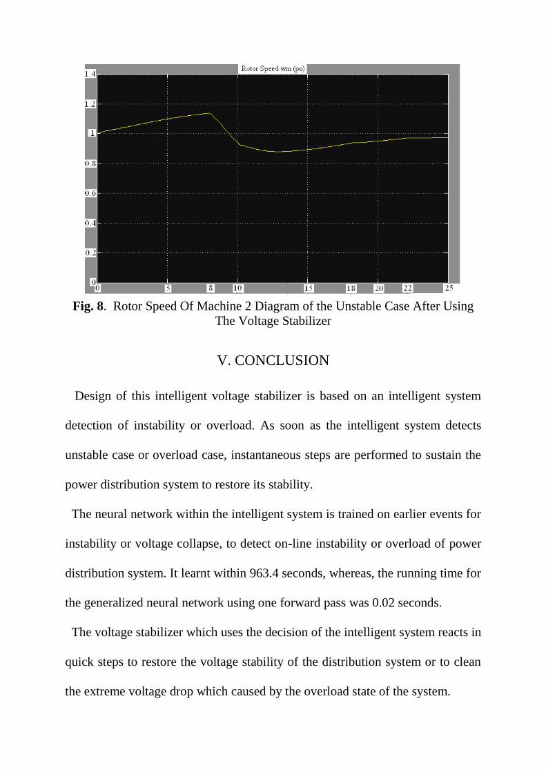
Fig. 8. Rotor Speed Of Machine 2 Diagram of the Unstable Case After Using
The Voltage Stabilizer
V. CONCLUSION
Design of this intelligent voltage stabilizer is based on an intelligent system
detection of instability or overload. As soon as the intelligent system detects
unstable case or overload case, instantaneous steps are performed to sustain the
power distribution system to restore its stability.
The neural network within the intelligent system is trained on earlier events for
instability or voltage collapse, to detect on-line instability or overload of power
distribution system. It learnt within 963.4 seconds, whereas, the running time for
the generalized neural network using one forward pass was 0.02 seconds.
The voltage stabilizer which uses the decision of the intelligent system reacts in
quick steps to restore the voltage stability of the distribution system or to clean
the extreme voltage drop which caused by the overload state of the system.

The stabilizer was tested with one overload case and one instability case. In the
overload case the VS is tested on an extreme voltage drop of the examined
distribution substation. The time consumed to achieve this voltage raise (0.214
p.u.) was 14 seconds. Although the least priority loads are shed, the other loads
still working in normal voltages and the system is far from voltage collapse. For
unstable cases the VS is tested on a case in which the rotor speed of other
generators was falling down quickly and the machines collapsed after machine 1
was lost. After shedding approximately 75% from loads the other machines
increase their speed and return the system stable preventing from system
collapse. The VS performed procedures to switch on the last ¼ shed loads
keeping the operating loads to work on nominal voltage. Although half loads
still shed the system restore stability preventing the machines to reach to
complete blackouts.
According to the above results, the proposed voltage stabilizer for power
distribution system is efficient in cleaning overload and restoring stability,
which suggest it to be implemented in PDS to work concurrent with SCADA
devices to prevent voltage collapse and blackouts of the power systems.
Future work and future development of the proposed system include
redesigning the voltage stabilizer to be fully intelligent by increasing the
dependence on the intelligent system to find the direct optimal solution to clean
the deep voltage drop or to find the optimal quantity of loads to be shed in order
to restore stability quickly.
REFERENCES
[1] G.M. Burt, J.R. McDonald, A.G. King, J. Spiller, D. Brooke, and R. Samwell
“Intelligent On-Line Decision Support for Distribution System Control and
Operation”, IEEE Transactions on Power Systems, Vol. 10, No. 4, 1995,
pp.1820-1827.
[2] H. Zhijian, C. Yunping, F. Dawei, L. Youwei, W. Linhu and G. Jianquan, “A
Novel Power System Stabilizer Based on Neural Network Inverse System”,
International Conference on Power System Technology - POWERCON
2004, Singapore, November 2004, pp. 21-24.
[3] Wenxin Liu, Ganesh K. Venayagamoorthy, Donald C. Wunsch II, “Adaptive
Neural Network Based Power System Stabilizer Design” IEEE Proceedings
of the International Joint Conference on Neural Networks, vol. 4, pp. 2970–
2975 (2003).
[4] R. Lukomski and K. Wilkosz, "Power System Topology Verification Using
Artificial Neural Network Utilization of Measurement Data", IEEE Power
Tech Conference, 2003, pp. 180-186.
[5] A. M. Azmy and I. Erlich, “Identification of Dynamic Equivalents for
Distribution Power Networks using Recurrent ANNs” IEEE Power systems
conf. and Exposition, IEEE PES, vol. 1, pp. 348-353, 2004.
[6] . N. Amjady, "Application of a New Neural Network to On-line Voltage
Stability Assessment", Journal of Elect. & Comp. Eng., Vol. 25, No. 2,
2000, pp. 69-75.
[7] S. Kamalasadan, A.K. Srivastava and D. Thukaram, "Novel Algorithm for
Online Voltage Stability Assessment Based on Feed Forward Neural
Network", IEEE Power Engineering Society General Meeting, Montreal
Canada, 2006, pp. 1-7.
[8] Bansilal, D. Thukaram and K. H. Kashyap, "Artificial Neural Network
Application to Power System Voltage Stability Improvement", IEEE
International Conference on Convergent Technologies for the Asia-Pacific
Region, TENCON 2003, Vol. 1, 15-17 Oct. 2003, pp. 53-57.
[9] M.M. Salama, E.M. Saied, M.M. Abou-Elsaad, and E.F. Ghariany,
"Estimating the Voltage Collapse Proximity Indicator Using Artificial Neural
Network", Energy Conversion and Management, vol. 42, no. 1, pp. 69-79,
Jan. 2001.
[10] G. Chicco, and R. Napoli, "Neural Network for Fast Voltage Prediction in
Power Systems", IEEE Power Tech Conference, 2001, pp. 312-316.
[11] M.A. Kashem, V. Ganapathy and G.B. Jamson, “On- line Network
Reconfiguration for Enhancement of Voltage Stability in Distribution
Systems using ANNs”, Electric Power Components and Systems Journal,
Vol. 29, pp. 361-373, April 2001.
[12] A.C.Z. De Souza, C.A. Canizers, and V.H. Quintana, "New Techniques to
Speed up Voltage Collapse Computations using Tangent Vectors", IEEE
Transactions on Power Systems, Vol. 12, No. 3, 1997, pp. 1380-1387.

[13] M. Ruiz, , J. Meléndez, J. Colomer, J. Sánchez, and M. Castro, "Fault
Location in Electrical Distribution Systems Using PLS and NN",
International Conference on Renewable Energy and Power Quality
ICREPQ'04, 2004, p. 264.
[14] A. Khashman, K. Buruncuk, and S. Jabr, " Intelligent Detection of
Voltage Instability in Power Distribution Systems", F. Sandoval et al. (Eds.):
Lecture Notes in Computer Science, IWANN 2007, LNCS 4507, pp. 870–
877, 2007, Springer-Verlag Berlin Heidelberg 2007
[15] A. Khashman, K. Buruncuk, and S. Jabr, " Voltage Instability Detection
Using Neural Nteworks", Encyclopedia of Artificial Intelligence / Juan
Ramon Rabunal Dopico, Julian Dorado de la Calle, and Alejandro Pazos
Sierra, editors, ISBN 978-1-59904-850-5 (ebook), pp. 1596–1602