intense terahertz pulses from slac electron beams using ... · review of scientific instruments 84,...
TRANSCRIPT

Intense terahertz pulses from SLAC electron beams using coherenttransition radiationZiran Wu, Alan S. Fisher, John Goodfellow, Matthias Fuchs, Dan Daranciang et al. Citation: Rev. Sci. Instrum. 84, 022701 (2013); doi: 10.1063/1.4790427 View online: http://dx.doi.org/10.1063/1.4790427 View Table of Contents: http://rsi.aip.org/resource/1/RSINAK/v84/i2 Published by the American Institute of Physics. Related ArticlesGenerating ultrabroadband terahertz radiation based on the under-compression mode of velocity bunching Rev. Sci. Instrum. 84, 022704 (2013) The TeraFERMI terahertz source at the seeded FERMI free-electron-laser facility Rev. Sci. Instrum. 84, 022702 (2013) Electron beam collimation with a 40000 tip metallic double-gate field emitter array and in-situ control of nanotipsharpness distribution J. Appl. Phys. 113, 043306 (2013) Generation of high-power tunable terahertz-radiation by nonrelativistic beam-echo harmonic effect Phys. Plasmas 20, 013303 (2013) Improvement of nonlinear harmonics in free electron laser with planar wiggler Phys. Plasmas 19, 113106 (2012) Additional information on Rev. Sci. Instrum.Journal Homepage: http://rsi.aip.org Journal Information: http://rsi.aip.org/about/about_the_journal Top downloads: http://rsi.aip.org/features/most_downloaded Information for Authors: http://rsi.aip.org/authors
Downloaded 23 Feb 2013 to 134.79.222.201. Redistribution subject to AIP license or copyright; see http://rsi.aip.org/about/rights_and_permissions

REVIEW OF SCIENTIFIC INSTRUMENTS 84, 022701 (2013)
Intense terahertz pulses from SLAC electron beams using coherenttransition radiation
Ziran Wu,1 Alan S. Fisher,1,a) John Goodfellow,2,3 Matthias Fuchs,3,4 Dan Daranciang,5
Mark Hogan,1 Henrik Loos,1 and Aaron Lindenberg2,3,4
1Accelerator Directorate, SLAC National Accelerator Laboratory, Stanford University, 2575 Sand Hill Road,Menlo Park, California 94025, USA2Department of Materials Science and Engineering, Stanford University, Stanford, California 94305, USA3Stanford Institute for Materials and Energy Science, SLAC National Accelerator Laboratory, Menlo Park,California 94025, USA4PULSE Institute for Ultrafast Energy Science, SLAC National Accelerator Laboratory, Menlo Park,California 94025, USA5Department of Chemistry, Stanford University, Stanford, California 94305, USA
(Received 10 October 2012; accepted 31 December 2012; published online 22 February 2013)
SLAC has two electron accelerators, the Linac Coherent Light Source (LCLS) and the Facility forAdvanced Accelerator Experimental Tests (FACET), providing high-charge, high-peak-current, fem-tosecond electron bunches. These characteristics are ideal for generating intense broadband terahertz(THz) pulses via coherent transition radiation. For LCLS and FACET respectively, the THz pulseduration is typically 20 and 80 fs RMS and can be tuned via the electron bunch duration; emissionspectra span 3–30 THz and 0.5 THz–5 THz; and the energy in a quasi-half-cycle THz pulse is 0.2 and0.6 mJ. The peak electric field at a THz focus has reached 4.4 GV/m (0.44 V/Å) at LCLS. This paperpresents measurements of the terahertz pulses and preliminary observations of nonlinear materialsresponse. © 2013 American Institute of Physics. [http://dx.doi.org/10.1063/1.4790427]
I. INTRODUCTION
The terahertz (THz) region of the electromagnetic spec-trum (roughly from 100 GHz to 10 THz) has long been used asa characterization tool, but in recent years the development ofnew, higher intensity sources, driven by both lasers and elec-tron beams, has created broad interest in using THz light forchemical and biological imaging, and opened up a new regimein which THz fields can be used to drive nonlinear responsesin matter. Other articles in this Special Edition discuss a rangeof sources and applications.
Spectroscopic applications prefer a source with a narrowfrequency span: a long pulse or a continuous source that istunable over the THz band. Time-resolved applications prefershort pulses in the single-cycle limit, with correspondinglywide bandwidths, to quickly “kick” a system into an excitedstate; after a delay of femtoseconds to picoseconds, the re-sponse is probed with, for example, an optical pulse from alaser.
A relativistic electron bunch in a linear accelerator (linac)can be compressed during acceleration to a length as short asa few fs, depending on the bunch charge. For wavelengthslonger than the bunch length, the emitted fields of all theelectrons in the bunch add coherently, and the total radi-ated power scales with the square of the number of elec-trons. The electron bunches described here have charges of100–3000 pC compressed to durations of 10–200 fs RMS,and so are well suited for the generation of intense THz
a)Author to whom correspondence should be addressed. Electronic mail:[email protected].
pulses. The electromagnetic fields traveling with the beamcan be converted to radiating fields in several ways: by bend-ing the beam in a strong magnetic field (coherent synchrotronradiation and coherent edge radiation, CSR and CER), bypassing the beam through a small aperture (coherent diffrac-tion radiation, CDR), or by passing the beam from vacuuminto a medium (coherent transition radiation, CTR). Severalaccelerator-based sources of THz radiation using these ap-proaches have been constructed.1–11
In CTR from a thin metallic foil, surface currents thatmatch boundary conditions on the foil produce the fields of acollapsing dipole as the electrons approach, and an expandingdipole as they leave, generating an impulse of dipole radiationon both sides.12 The temporal shape has a long-wavelengthcutoff due to the finite size of the foil and apertures. Withoutthese low frequencies, the shortest pulse resembles a “quasi-half-cycle,” with a high-amplitude central pulse of one polar-ity and two longer but weaker lobes of opposite polarity be-fore and after. For highly relativistic electrons, the radiationemitted on exit from the foil travels in the beam direction,while the entrance radiation goes in the direction of specu-lar reflection from the foil surface. By tilting the foil at 45◦
to the electron beam, this entrance radiation can be quicklyextracted.
SLAC National Accelerator Laboratory has two suchTHz sources, at the Facility for Advanced Accelerator Ex-perimental Tests (FACET) and at the Linac Coherent LightSource (LCLS). The former uses the first 2 km of the 3-kmSLAC linear accelerator, while the latter uses the third km(Figure 1). Both sources use CTR, which offers a small andwell defined source point (unlike CSR) and the absence of ashort-wavelength cutoff from the hole in CDR. A multi-GeV
0034-6748/2013/84(2)/022701/10/$30.00 © 2013 American Institute of Physics84, 022701-1
Downloaded 23 Feb 2013 to 134.79.222.201. Redistribution subject to AIP license or copyright; see http://rsi.aip.org/about/rights_and_permissions

022701-2 Wu et al. Rev. Sci. Instrum. 84, 022701 (2013)
FIG. 1. The 3-km SLAC linac, divided into FACET and LCLS linacs. THz sources are in the FACET experimental area and in the LCLS undulator hall.
beam experiences little scattering when passing through a thin(≤10 μm) foil.
A. FACET
The Facility for Advanced Accelerator ExperimentalTests13 provides 3.2-nC electron (and, in future, positron)bunches at 20–23 GeV, compressed to lengths as short as67 fs RMS, corresponding to a peak current of over 20 kA(Table I). The beam is tightly focused at the interaction point(IP), a long optical table for user experiments (Figure 2).Advanced acceleration concepts are a major emphasis, no-tably electron acceleration in wakefields in plasmas14 and alsoin dielectrics.15 Both depend on the longitudinal bunch pro-file, which is measured by a new transverse deflecting cavityand by two THz experiments. The first studies Smith-Purcellradiation.16 The second, which is presented here, uses CTR.
B. LCLS
The Linac Coherent Light Source is the world’s firsthard x-ray free-electron laser (FEL).17 Self-amplified spon-
TABLE I. FACET parameters.
Typical Best Design
Electron energy (GeV) 20.35 21.1 23Charge per bunch (pC) 2500–2900 3200 3200Repetition rate (Hz) 10 10 30Bunch length
σ z (μm) 25–30 <25 20σ t (fs) 83–100 <83 67
Size at IPσ x (μm) 35 20 20σ y (μm) 35 23 20
Standard Optics Double WaistSize at upstreamTHz foil
σ x (μm) 1200 317σ y (μm) 6 36
taneous emission along more than 100 m of undulator pro-duces coherent x-ray pulses. The electron energy is tunedover a broad energy range (Table II) to provide a wide rangeof photon energies, down to wavelengths as short as 1.3 Å.
FIG. 2. The THz and IP tables of FACET.
Downloaded 23 Feb 2013 to 134.79.222.201. Redistribution subject to AIP license or copyright; see http://rsi.aip.org/about/rights_and_permissions

022701-3 Wu et al. Rev. Sci. Instrum. 84, 022701 (2013)
FIG. 3. Layout of the FACET THz table.
Recent progress in x-ray self-seeding18 offers nearly Fourier-transform-limited pulses of hard x-rays.
II. TERAHERTZ AT FACET
A. Setup
To provide sufficient space for optics while avoiding in-terference with experiments on the IP table, the THz sourceat FACET is on a separate optical table, 10 m upstream ofthe IP (Figure 2). The THz radiator is a 1-μm-thick tita-nium foil rotated about the vertical axis by 45◦. As elec-trons enter the foil, the THz they emit exits horizontally at
TABLE II. LCLS parameters.
Electrons
Energy (GeV) 2.6–14.7Charge per bunch (pC) 20–350Repetition rate (Hz) 120Bunch length
σ z (μm) 1.5–75σ t (fs) 5–250
Size at THz foilσ x,y (μm) 50–70
X RaysPhoton energy (eV) 300–9600Pulse energy (mJ) 0.1–3
90◦ to the electron direction. The radiation passes through a25-mm-diameter, 0.25-mm-thick, diamond window and iscollimated by an off-axis parabolic mirror (OAP). Instrumentson the table (Figure 3) characterize the THz pulses. A pyro-electric joulemeter gives the energy, knife-edge scans mea-sure the size at the focus of another OAP, and a Michelsoninterferometer provides the spectrum. The entire tabletop isenclosed (Figure 4) and continually purged with dry air toavoid the strong absorption of THz by water vapor.
The THz table is located after the final bunch compres-sor but in the middle of the sequence of quadrupole magnets
FIG. 4. FACET THz table and dry-air enclosure.
Downloaded 23 Feb 2013 to 134.79.222.201. Redistribution subject to AIP license or copyright; see http://rsi.aip.org/about/rights_and_permissions

022701-4 Wu et al. Rev. Sci. Instrum. 84, 022701 (2013)
FIG. 5. Calculated (a) CTR electric field, (b) electron-bunch peak current,and (c) CTR power spectrum, using the parameters discussed in the text.
that make the final focus at the IP. With standard IP optics,the nominal beam size at the upstream THz foil (Table I) ishighly elliptical, with σ x = 1.2 mm and σ y = 6 μm at theupstream foil, and 1.5 mm by 13 μm at the downstream foil.The emitted THz energy is reduced for wavelengths shorterthan this transverse size, since the fields of the particles in-terfere destructively. Retuning the quadrupole magnets for amore circular spot at the THz foil gives a shallow waist of317 μm by 36 μm while retaining the small focus at the IP.The measurements reported here use this “double-waist” con-figuration (Table I).
The 1-μm foil thickness is a trade-off between the effectof multiple Coulomb scattering on beam quality and the skindepth, 0.33 μm at 1 THz, which reduces reflectivity and so the
CTR yield below 1 THz. Titanium, a light and strong metalwith a high melting temperature, was expected to be resistantto beam damage. However, the beam has punctured severalof these foils on the IP table, near the minimum beam radius,and one foil on the THz table. The damage does not appear tobe driven thermally but instead by the peak field, for reasonselaborated in Sec. III A. Other foil materials will be tested inthe 2013 FACET run.
B. Simulations
The THz power and spectrum radiated by CTR was cal-culated with a code19, 20 developed at SLAC. The foil is mod-eled as a perfectly conducting boundary with a unity reflec-tion coefficient. Figure 5 plots the calculated electric field ofa 3-nC electron bunch, at an energy of 23 GeV, with a 50-fs length and a 10-μm diameter. For this case, the peak cur-rent is roughly 27 kA and the maximum electric field reaches0.6 V/Å in the ∼150 fs long quasi-half cycle pulse. The powerspectrum peaks at 1.2 THz (40 cm−1), with significant contentup to 6 THz (200 cm−1). The energy per pulse is 13 mJ. Thebunch dimensions used were significantly smaller than thoseavailable later in the experiment, but the high fields and pulseenergy show FACET’s potential as a THz source.
Because the experiment initially used the standard op-tics of Table I, with a ribbon-like beam, another simulationstudied the effect on the CTR of the ribbon compared to a cir-cular beam. This required a different code21 that follows Ter-Mikaelian.12 Figure 6 shows the CTR radiation spectrum, nor-malized to the square of the charge and integrated over solidangle. The dashed curve corresponds to the elliptical spot ofstandard optics (Table I, σ x = 1.2 mm, σ y = 6 μm), the solidline to the double waist (σ x = 317 μm, σ y = 36 μm), and thedotted curve to an 85-μm circular beam. With double-waistoptics, the power at frequencies near 0.5 THz increases bymore than a factor of 2, and the circular beam provides aneven greater improvement.
C. Measurements
Figure 7(a) shows a typical Michelson interferogram ofTHz emitted by a highly compressed FACET electron bunch.The pyroelectric detector readings are averaged over 10 shots
FIG. 6. Calculations comparing the spectrum of the ribbon beam of standard optics (dashed line) to the double waist (solid) and to an 85-μm circular beam(dotted).
Downloaded 23 Feb 2013 to 134.79.222.201. Redistribution subject to AIP license or copyright; see http://rsi.aip.org/about/rights_and_permissions

022701-5 Wu et al. Rev. Sci. Instrum. 84, 022701 (2013)
FIG. 7. (a) Michelson interferogram of a CTR THz pulse from a highly compressed electron bunch. The points are normalized to the reference detector.(b) Normalized power spectra of THz pulses from bunches with low and high compression.
and normalized to readings from a reference pyro detectorright before the interferometer (Figure 3). The 4-mm scan hasa resolution of 37 GHz in the frequency domain.
Fourier transforms of the scans give power spectra.Figure 7(b) shows the change in spectral content for high andlow bunch compression. Strong water absorption lines near1.3 THz are not present, due to the low humidity inside the en-closure. We attribute the 0.24-THz modulation in both spec-tra to Fabry-Pérot interference in reflections from the layersof the pyroelectric detector. The spectra were smoothed to re-duce this effect.
The spectrum can be used to reconstruct the temporalprofile of a bunch. Although the wakefield of a relativisticbunch follows the bunch shape, the fields radiated by the foilare filtered by the finite beampipe and window, and so loselong wavelengths. To compensate the spectrum for this loss,
we model the attenuation of the field as a Gaussian high-pass filter,22 1−exp(−f 2/f02), which leads to negative lobeson either side of the main peak of the interferogram. Withdata from a highly compressed beam, which has a nearlyGaussian profile, we fit the center of the autocorrelation inthe time domain (Figure 8(a)) with a Gaussian beam and fil-ter to find the filter constant f0. For FACET, f0 lies between0.35 and 0.45 THz, depending on the adjustment of the op-tics. We then discard the assumption of a Gaussian beambut retain f0. The power spectrum is compensated by divid-ing by the square of the filter down to frequencies near f0,where the correction starts to diverge and where little signalis available. From this point down to zero frequency, the cor-rection is completed by fitting a Gaussian peaking at f = 0(Figure 8(b)). Empirically, it is found that the reconstruc-tion does not depend strongly on the detailed shape at the
FIG. 8. (a) Central region of the autocorrelation of Figure 7(a), after subtracting the mean, with a fit about the peak to find the high-pass filter. (b) The high-compression spectrum (dashed line) of Figure 7(b) is compensated (solid) for the high-pass filter, down to the leftmost circled point, below which a Gaussian fitto all the circled points extends the curve to f = 0.
Downloaded 23 Feb 2013 to 134.79.222.201. Redistribution subject to AIP license or copyright; see http://rsi.aip.org/about/rights_and_permissions
022701-6 Wu et al. Rev. Sci. Instrum. 84, 022701 (2013)
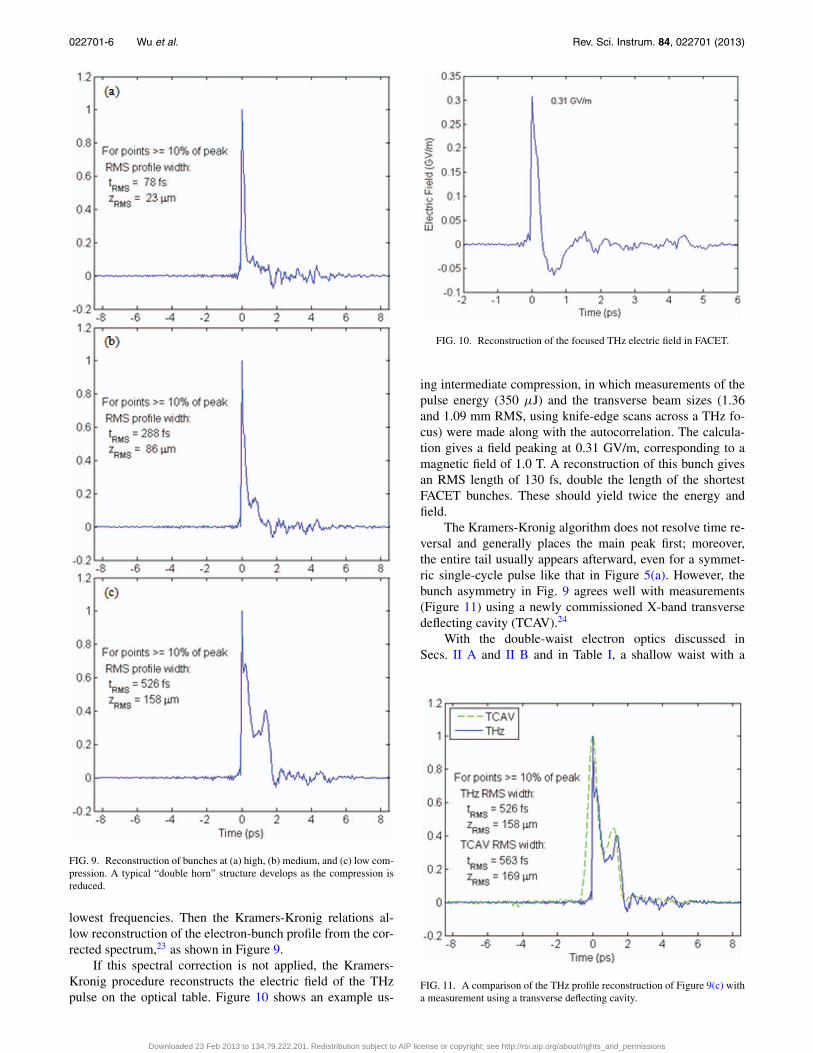
FIG. 9. Reconstruction of bunches at (a) high, (b) medium, and (c) low com-pression. A typical “double horn” structure develops as the compression isreduced.
lowest frequencies. Then the Kramers-Kronig relations al-low reconstruction of the electron-bunch profile from the cor-rected spectrum,23 as shown in Figure 9.
If this spectral correction is not applied, the Kramers-Kronig procedure reconstructs the electric field of the THzpulse on the optical table. Figure 10 shows an example us-
FIG. 10. Reconstruction of the focused THz electric field in FACET.
ing intermediate compression, in which measurements of thepulse energy (350 μJ) and the transverse beam sizes (1.36and 1.09 mm RMS, using knife-edge scans across a THz fo-cus) were made along with the autocorrelation. The calcula-tion gives a field peaking at 0.31 GV/m, corresponding to amagnetic field of 1.0 T. A reconstruction of this bunch givesan RMS length of 130 fs, double the length of the shortestFACET bunches. These should yield twice the energy andfield.
The Kramers-Kronig algorithm does not resolve time re-versal and generally places the main peak first; moreover,the entire tail usually appears afterward, even for a symmet-ric single-cycle pulse like that in Figure 5(a). However, thebunch asymmetry in Fig. 9 agrees well with measurements(Figure 11) using a newly commissioned X-band transversedeflecting cavity (TCAV).24
With the double-waist electron optics discussed inSecs. II A and II B and in Table I, a shallow waist with a
FIG. 11. A comparison of the THz profile reconstruction of Figure 9(c) witha measurement using a transverse deflecting cavity.
Downloaded 23 Feb 2013 to 134.79.222.201. Redistribution subject to AIP license or copyright; see http://rsi.aip.org/about/rights_and_permissions

022701-7 Wu et al. Rev. Sci. Instrum. 84, 022701 (2013)
FIG. 12. The FACET electron beam on the upstream THz foil, imaged with the same scale using optical transition radiation, for (a) standard and (b) double-waistelectron optics.
more circular electron beam is formed at the upstream THzfoil. Figure 12 compares optical-transition-radiation imagesof the transverse spot on the foil with the standard and double-waist configurations; the size scales as expected. The THz en-ergy per pulse increased by 33%, from 0.47 to 0.63 mJ, andthe spectrum shows more high-frequency content in qualita-tive agreement with Figure 6. Quadrupole settings have beencalculated to produce even smaller sizes, including the cir-cular spot of Figure 6, when the constraint of a small sizeat the IP is lifted. Dedicated beam time to test these opticalconfigurations has been requested during the 2013 run in or-der to determine the largest transverse size consistent withmaximum CTR.
III. TERAHERTZ AT LCLS
A. Setup
The LCLS THz source is located in the Undulator Hall,31 m downstream of the undulator. Measurements have beencarried out at electron energies of 14 GeV with bunch chargesfrom 150 – 350 pC. A beryllium foil tilted downward by 45◦
sends THz through a 25-mm-diameter, 0.25-mm-thick dia-mond window to optics on a table below. These include char-acterization measurements similar to those at FACET, plusa 20-fs Ti:sapphire oscillator, for THz-pump and laser-probestudies. The reflection and transmission of a variety of sam-ples can be measured as they are exposed to intense THzpulses. Again the tabletop is enclosed, both for a dry-air purgeand for laser safety.
Initial measurements used a 2-μm-thick beryllium foil, ametal chosen both for low scattering of the electron beam andfor weak absorption of FEL x rays that also pass through thebeampipe. The skin depth for Be is 95 nm at 1 THz. This foilwas broken after several months when a vacuum-valve con-troller malfunctioned. To avoid the toxicity of Be particulates,aluminum was substituted. Maintaining low x-ray absorptionrequired a 500-nm thickness, which is still much larger thanthe 85-nm skin depth at 1 THz.
The electron beam punctured three Al foils, even whenthe undulators were pulled away from the beam so that noFEL x rays were produced. In a systematic study with a con-stant charge of 150 pC and a low 10-Hz repetition rate, thebunch was gradually compressed. No damage was seen un-
til the bunch length was reduced to 100 fs FWHM. Then avideo camera detected light emitted from the beam positionon the foil, and within seconds a small hole (∼1 mm) was vis-ible. We concluded that damage depending on compression atthe femtosecond timescale cannot be thermal but is likely amechanism driven by the peak field of the bunch, such as asurface discharge. Material selection by thermal and mechan-ical properties is not sufficient. We resumed work with Be,but with a 10-μm-thickness and a new holder that parks theBe when not in use inside a volume with low conductance tothe beampipe. This design slows a sudden pressure rise andequalizes the pressure on both sides of the foil. Be has provento be resistant to beam damage, even at full charge (350 pC)and compression (50 fs FHWM).
B. Simulations
Simulations of the radiated field strength and temporalprofile are similar to those described above for FACET. Thespatio-temporal electron beam profile is obtained by a simu-lation of the entire LCLS accelerator using Impact-T and El-egant codes.25 The initial electric field at the Be foil is trans-formed into a frequency-domain profile and propagated usingLaguerre-Gaussian modes through the optical setup, includ-ing diffraction effects from the finite size of the foil. Thesesimulations calculate the full extracted spatio-temporal THzfield at the focus of the optical setup, predicting a radiallypolarized beam with zero intensity on axis, reflecting the rel-ativistic Coulomb field of the electron bunch. For the highestcharge and shortest bunch measured (350 pC, 50 fs FWHM),at the focus of an OAP with an effective focal length of150 mm (NA = 0.1), the model predicts a 400-μm FWHMtransverse profile and a peak field 100 μm from the axis of7 GV/m (0.7 V/Å). Integrating over the temporal and spatialprofile gives a radiated energy of 560 μJ.
C. Measurements
Total energy measurements of the radiated THz fields arecarried out using several methods to check for consistency. Athermopile power meter with a graphite absorber and a pyro-electric detector (Gentec) were used initially, with maximumrecorded energy of ∼200 μJ/pulse. The energy may be higher,since Gentec later provided preliminary calibration correction
Downloaded 23 Feb 2013 to 134.79.222.201. Redistribution subject to AIP license or copyright; see http://rsi.aip.org/about/rights_and_permissions

022701-8 Wu et al. Rev. Sci. Instrum. 84, 022701 (2013)
FIG. 13. Electron-beam energy loss due to inserting the 2-μm Be foil.
factors of 2.1–4 at 2.52 THz, depending on the detector type.Similarly, the graphite in the thermopile is not a perfect THzabsorber.
The total radiated THz energy can also be obtained bymeasuring the energy loss of the electrons due to CTR, an ap-proach not subject to uncertainties about the broadband cali-bration of the detectors. The bend at the electron beam dumpwas designed as an energy spectrometer, allowing us to com-pare the deflection with the foil radiator in and out of thebeam. The electron beam is estimated to lose only 30 μJ ina 2-μm Be foil tilted at 45◦, and 150 μJ in a 10-μm foil.26
Figure 13 shows measurements with the 2-μm Be foil indi-cating an 8.7-MeV loss per electron, corresponding to a 2.9-
mJ loss for 350 pC. Half of this THz is radiated in the for-ward direction as the beam exits the foil. The radiation onentrance heads downward, but 30% is lost by reflection fromthe high-index diamond window, so that about 1 mJ would beexpected on the table. Additional losses, particularly absorp-tion by water vapor (before the enclosure was installed) re-duce these fields by another factor of ∼2. This approach pro-vides a complimentary estimate of the radiated fields. Giventhe uncertainties, the simulations and the energy loss are inreasonable agreement with the detector measurements.
For a charge q and pulse duration t, the radiated THz fieldis expected to scale with the time-dependent peak current q/t,and the intensity with q2/t2. Integrating over time, the radiatedenergy then scales with q2/t. Figure 14 shows measurementswhich roughly confirm this scaling law, using (a) a pyroelec-tric detector at a THz focus, and (b) the electron energy loss.This scaling cannot be precise: the bunch shape changes withcompression, becoming more peaked and increasing emissionfaster than 1/t. Also, the nominal bunch length in the figurewas taken from a monitor measuring filtered infrared from abend at the end of the final compressor. It was calibrated witha transverse deflecting cavity, but the bandpass filter makes itsomewhat inaccurate for the shortest bunches. The best fit tothe above scaling offsets the bunch length by approximately20 fs.
As with FACET, the Kramers-Kronig procedure can re-construct the temporal profile of the electric field from an au-tocorrelation. Using a measured autocorrelation of a 350-pC,70-fs FWHM bunch and a typical energy of 180 μJ from Fig-ure 14, the reconstruction in Figure 15 calculates a peak fieldof 4.4 GV/m at the focus on the optical table. This field ismuch stronger than the FACET field in Figure 10 since thisenergy is contained in a shorter bunch and a smaller focalspot, 200 μm RMS. The smaller source size and shorter bunch
FIG. 14. Dependence of THz energy on charge and FWHM bunch duration, measured by (a) a pyroelectric joulemeter at a THz focus, and (b) the electron-beamenergy loss.
Downloaded 23 Feb 2013 to 134.79.222.201. Redistribution subject to AIP license or copyright; see http://rsi.aip.org/about/rights_and_permissions

022701-9 Wu et al. Rev. Sci. Instrum. 84, 022701 (2013)
FIG. 15. Reconstruction of the focused THz field in LCLS.
result in a spectrum with higher frequencies, peaking at 10THz,11 and thus allow a tighter focus.
Further evidence for the high field strength is provided bynonlinear autocorrelations. The field (linear) autocorrelationshown in Figure 7(a) provides a direct measurement of thespectrum of the radiated field. The peak-to-baseline ratio forsuch scans is limited to 2, with a perfect overlap of the fields inspace and time on the pyroelectric detector. In other autocor-relations, two THz pulses were incident collinearly on a sili-con photodiode, which provides an intrinsically nonlinear re-sponse since its 1.1-eV bandgap is well above the THz photonenergy.27 Figure 16 plots the diode’s photocurrent as a func-tion of the relative time delay between the two THz fields fora bunch with intermediate compression (90 fs FWHM for 350pC). The scan shows the 3-peak autocorrelation expected fora double-horn distribution,11 but with a high peak-to-baselineratio of 9 that indicates the photodiode’s strongly nonlinearresponse to the high fields.
FIG. 16. A nonlinear autocorrelation measured with a silicon photodiode.
ACKNOWLEDGMENTS
This work was supported by the U.S. Department of En-ergy under Contract DE-AC02-76SF00515. The Linac Coher-ent Light Source (LCLS) and at the Facility for AdvancedAccelerator Experimental Tests (FACET) are User Facilitiesat SLAC National Accelerator Laboratory operated for theU.S. Department of Energy, Office of Science, by StanfordUniversity. The authors gratefully acknowledge the supportof the DOE Office of Basic Energy Sciences for LCLS andthe Office of High-Energy Physics for FACET, and A.L. alsoacknowledges the support of the Office of Basic Energy Sci-ences, Materials Sciences and Engineering Division.
M.F. gratefully acknowledges financial support from theVolkswagen Foundation. J.G. is supported in part by the De-partment of Energy Office of Science Graduate FellowshipProgram (DOE SCGF), made possible in part by the Ameri-can Recovery and Reinvestment Act of 2009, administered byORISE-ORAU (Contract No. DE-AC05-06OR23100).
1G. L. Carr, M. C. Martin, W. R. McKinney, K. Jordan, G. R. Neil, and G.P. Williams, “High-power terahertz radiation from relativistic electrons,”Nature 420, 153–156 (2002).
2J. van Tilborg, C. B. Schroeder, C. V. Filip, Cs. Tóth, C. G. R. Geddes, G.Fubiani, R. Huber, R. A. Kaindl, E. Esarey, and W. P. Leemans, “Temporalcharacterization of femtosecond laser-plasma-accelerated electron bunchesusing terahertz radiation,” Phys. Rev. Lett. 96, 014801 (2006).
3M. C. Hoffmann, S. Schulz, S. Wesch, S. Wunderlich, A. Cavalleri, and B.Schmidt, “Coherent single-cycle pulses with MV/cm field strengths froma relativistic transition radiation light source,” Opt. Lett. 36, 4473–4475(2011).
4T. Takahashi, Y. Shibata, F. Arai, K. Ishi, T. Ohsaka, M. Ikezawa, Y.Kondo, T. Nakazato, S. Urasawa, and R. Kato, “Coherent transition radia-tion at submillimeter and millimeter wavelengths,” Phys. Rev. E 48, 4674(1993).
5S. Casalbuoni, B. Schmidt, P. Schmüser, V. Arsov, and S. Wesch, “Ultra-broadband terahertz source and beamline based on coherent transition ra-diation,” Phys. Rev. ST Accel. Beams 12, 030705 (2009).
6C. S. Thongbai and T. Vilaithong, “Coherent transition radiation from shortelectron bunches,” Nucl. Instrum. Methods A 581, 874 (2007).
7D. Mihalcea, C. Bohn, U. Happek, and P. Piot, “Longitudinal electronbunch diagnostics using coherent transition radiation,” Phys. Rev. ST Ac-cel. Beams 9, 082801 (2006).
8Y. Shen, T. Watanabe, D. A. Arena, C.-C. Kao, J. B. Murphy, T. Y. Tsang,X. J. Wang, and G. L. Carr, “Nonlinear cross-phase modulation with in-tense single-cycle terahertz pulses,” Phys. Rev. Lett. 99, 043901 (2007).
9T. Nakazato, M. Oyamada, N. Niimura, S. Urasawa, O. Konno, A. Kagaya,R. Kato, T. Kamiyama, Y. Torizuka, and T. Nanba, “Observation of coher-ent synchrotron radiation,” Phys. Rev. Lett. 63, 1245 (1989).
10G. Andonian, A. Cook, M. Dunning, E. Hemsing, G. Marcus, A. Murokh,S. Reiche, D. Schiller, J. B. Rosenzweig, M. Babzien, K. Kusché, andV. Yakimenko, “Observation of coherent terahertz edge radiation fromcompressed electron beams,” Phys. Rev. ST Accel. Beams 12, 030701(2009).
11D. Daranciang, J. Goodfellow, M. Fuchs, H. Wen, S. Ghimire, D. A. Reis,H. Loos, A. S. Fisher, and A. M. Lindenberg, “Single-cycle terahertz pulseswith >0.2 V/Å field amplitudes via coherent transition radiation,” Appl.Phys. Lett. 99, 141117 (2011).
12M. L. Ter-Mikaelian, High-Energy Electromagnetic Processes in Con-densed Media (Wiley, New York, 1972).
13C. I. Clarke, F. J. Decker, R. J. England, R. Erikson, C. Hast, M. J. Hogan,S. Z. Li, M. Litos, Y. Nosochkov, J. Seeman, J. Sheppard, U. Wienands,M. Woodley, and G. Yocky, “FACET: SLAC’s New User Facility,” SLAC-PUB-15025, May 2012.
14I. Blumenfeld, C. E. Clayton, F.-J Decker, M. J. Hogan, C. Huang, R. Is-chebeck, R. Iverson, C. Joshi, T. Katsouleas, N. Kirby, W. Lu, K. A. Marsh,W. B. Mori, P. Muggli, E. Oz, R. H. Siemann, D. Walz, and M. Zhou, “En-ergy doubling of 42 GeV electrons in a metre-scale plasma wakefield ac-celerator,” Nature 445, 741 (2007).
Downloaded 23 Feb 2013 to 134.79.222.201. Redistribution subject to AIP license or copyright; see http://rsi.aip.org/about/rights_and_permissions

022701-10 Wu et al. Rev. Sci. Instrum. 84, 022701 (2013)
15G. Andonian, D. Stratakis, M. Babzien, S. Barber, M. Fedurin, E. Hemsing,K. Kusché, P. Muggli, B. O’Shea, X. Wei, O. Williams, V. Yakimenko,and J. B. Rosenzweig, “Dielectric wakefield acceleration of a relativisticelectron beam in a slab-symmetric dielectric lined waveguide,” Phys. Rev.Lett. 108, 244801 (2012).
16V. Blackmore, G. Doucas, B. Ottewell, C. Perry, M. F. Kimmitt, R. Arnold,S. Molloy, and M. Woods, “First measurements of the longitudinal bunchprofile at SLAC using coherent Smith-Purcell radiation at 28 GeV,” SLAC-PUB-13499, November 2011.
17P. Emma et al., “First lasing and operation of an ångstrom-wavelength free-electron laser,” Nature Photon. 4, 641–647 (2010).
18J. Amann et al., “Demonstration of self-seeding in a hard-X-ray free-electron laser,” Nature Photon. 6, 693–698 (2012).
19H. Loos, R. Akre, A. Brachmann, F.-J. Decker, Y. Ding, D. Dowell, P.Emma, J. Frisch, S. Gilevich, G. Hays, Ph. Hering, Z. Huang, R. Iverson,C. Limborg-Deprey, A. Miahnahri, S. Molloy, H.-D. Nuhn, J. Turner, J.Welch, W. White, and J. Wu, “Observation of coherent optical transitionradiation in the LCLS LINAC,” SLAC-PUB-13395, September 2008.
20J. D. Jackson, “Collisions, energy loss, and scattering of charged particles,
Cherenkov and transition radiation,” in Classical Electrodynamics (Wiley,New York, 1975).
21J. England, SLAC, private communication (2011).22A. Murokh, J. B. Rosenzweig, M. Hogan, H. Suk, G. Travish, and U.
Happek, “Bunch length measurement of picosecond electron beams from aphotoinjector using coherent transition radiation,” Nucl. Instrum. MethodsA 410, 452 (1998).
23R. Lai and A. J. Sievers, “On using the coherent far IR radiation producedby a charged-particle bunch to determine its shape: I Analysis,” Nucl. In-strum. Methods A 397, 221 (1997).
24M. Litos, SLAC, private communication (2012).25J. Qiang, S. Lidia, R. Ryne, and C. Limborg-Deprey, “Three-dimensional
quasistatic model for high brightness beam dynamics simulation,” Phys.Rev. ST Accel. Beams 9, 044204 (2006).
26A Physicist’s Desk Reference, the Physics Vade Mecum, 2nd ed., edited byH. L. Anderson (Springer, 1989), p. 260, sec. 16.07.F.
27K. Briggman, L. Richter, and J. Stephenson, “Imaging and autocorrelationof ultrafast infrared laser pulses in the 3-11 micron range with silicon CCDcameras and photodiodes,” Opt. Lett. 26, 238 (2001).
Downloaded 23 Feb 2013 to 134.79.222.201. Redistribution subject to AIP license or copyright; see http://rsi.aip.org/about/rights_and_permissions