intention-aware sliding doors
TRANSCRIPT

Master of Science in Computer ScienceJune 2011Anders Kofod-Petersen, IDIRichard Blake, IDIRebekah Wegener, Macquarie University, NSW,Australia
Submission date:Supervisor:Co-supervisor:
Norwegian University of Science and TechnologyDepartment of Computer and Information Science
Intention-aware Sliding Doors
John Sverre Solem


ii
“report” — 2011/6/20 — 15:25 — page i — #1 ii
ii
ii
Problem Description
Truly smart systems need to interface with the behavior of human and non-humanactors in their surroundings and on their terms.
This project aims to develop an intelligent sliding door, which responds to userintentions. The system is to be developed on a physical door using artificial vision.
Assignment given: 17. January 2011, by Anders Kofod-Petersen (supervisor)

ii
“report” — 2011/6/20 — 15:25 — page ii — #2 ii
ii
ii
ii
ii
“report” — 2011/6/20 — 15:25 — page iii — #3 ii
ii
ii
Abstract
You can see sliding doors everywhere, be it at the grocery store or the hospital.These doors are today mostly based on naive motion sensing, and hence not veryintelligent in deciding to open or not. Ignoring the user’s intention, can result in amiscommunication between the door and the user, most often leading to erroneousopenings of the door. I try to solve this problem by using a Kinect sensor capturinghuman activity in front of a door. The users are then detected and skeletal jointstracked using the OpenNI framework. Features are extracted according to a modelof human behavior and intentions. A rule-based reasoning mechanism then makesa decision whether to open the door or not. In this project I have generalized adoor user’s behavior creating a model of symbols and events. I have implementeda program that can identify these events and operate a door based on the inferredintention. I have also built a door that is able to demonstrate the functionality ofthe program. The intention-aware, intelligent sliding door achieved an accuracy of77-86 % in the performed test cases.
Keywords: Computer Vision, Artificial Intelligence, Intention recognition, Be-havioral model, Rule-based reasoning, Intention-awareness, Sliding door, XboxKinect, OpenNI.

ii
“report” — 2011/6/20 — 15:25 — page iv — #4 ii
ii
ii
iv

ii
“report” — 2011/6/20 — 15:25 — page v — #5 ii
ii
ii
Preface
This master’s thesis describes the study and work from my master’s project. Theproject is the closure of my degree in Computer Science at the Department ofComputer and Information Science at the Norwegian University of Science andTechnology. The project is a continuation of a specialization project, performedby a fellow student, Havar Aambø Fosstveit, and I. Some of the material presentedin this thesis will therefore originate from the specialization project report. Sec-tion 2.2 is in special written together with Havar Aambø Fosstveit. In connectionwith a submission to SCAI, Richard Blake also contributed in rewriting parts ofthis section.

ii
“report” — 2011/6/20 — 15:25 — page vi — #6 ii
ii
ii
vi

ii
“report” — 2011/6/20 — 15:25 — page vii — #7 ii
ii
ii
Acknowledgements
This project would not be possible without the continuous help and support frommy supervisor, Anders Kofod-Petersen. I would like to thank him for his invalu-able advice and assistance throughout the entire project. I would also extend mygratitude to my co-supervisors; Richard Blake for many encouraging meetings andhelp in computer vision, and Rebekah Wegener for supplying me with resourcesand insight within the area of semiotics. Finally, I would like to thank my lovelywife, for standing by my side, and supporting me.
John Sverre SolemTrondheim, June 20, 2011

ii
“report” — 2011/6/20 — 15:25 — page viii — #8 ii
ii
ii
viii

ii
“report” — 2011/6/20 — 15:25 — page ix — #9 ii
ii
ii
Contents
1 Introduction and Overview 11.1 Background and Motivation . . . . . . . . . . . . . . . . . . . . . . 11.2 Goals and Research Questions . . . . . . . . . . . . . . . . . . . . . 21.3 Contributions . . . . . . . . . . . . . . . . . . . . . . . . . . . . . . 31.4 Research Method . . . . . . . . . . . . . . . . . . . . . . . . . . . . 31.5 Thesis Structure . . . . . . . . . . . . . . . . . . . . . . . . . . . . . 7
2 Theory and Background 92.1 Human Behavior and Intention . . . . . . . . . . . . . . . . . . . . 10
2.1.1 Model . . . . . . . . . . . . . . . . . . . . . . . . . . . . . . 102.2 Computer Vision . . . . . . . . . . . . . . . . . . . . . . . . . . . . 11
2.2.1 Computer Vision Tools . . . . . . . . . . . . . . . . . . . . . 132.3 Reasoning . . . . . . . . . . . . . . . . . . . . . . . . . . . . . . . . 17
2.3.1 Bayesian Network . . . . . . . . . . . . . . . . . . . . . . . . 182.3.2 Decision Network . . . . . . . . . . . . . . . . . . . . . . . . 192.3.3 Hidden Markov Model . . . . . . . . . . . . . . . . . . . . . 202.3.4 Rule-Based reasoning . . . . . . . . . . . . . . . . . . . . . . 212.3.5 Machine learning . . . . . . . . . . . . . . . . . . . . . . . . 21
3 Research Results 253.1 Modeling human behavior . . . . . . . . . . . . . . . . . . . . . . . 25
3.1.1 Motion . . . . . . . . . . . . . . . . . . . . . . . . . . . . . . 253.1.2 Proximity . . . . . . . . . . . . . . . . . . . . . . . . . . . . 263.1.3 Body alignment . . . . . . . . . . . . . . . . . . . . . . . . . 263.1.4 From feature to intention . . . . . . . . . . . . . . . . . . . . 26
3.2 Capturing the intention . . . . . . . . . . . . . . . . . . . . . . . . 283.2.1 Evaluation of computer vision tools . . . . . . . . . . . . . . 283.2.2 Kinect and OpenNI . . . . . . . . . . . . . . . . . . . . . . . 303.2.3 Calculating the features of interest . . . . . . . . . . . . . . 31
3.3 To open or not to open . . . . . . . . . . . . . . . . . . . . . . . . . 363.3.1 Defining rules . . . . . . . . . . . . . . . . . . . . . . . . . . 36
ii
“report” — 2011/6/20 — 15:25 — page x — #10 ii
ii
ii
x Contents
3.3.2 Avoiding false positives . . . . . . . . . . . . . . . . . . . . . 383.4 An automated sliding door . . . . . . . . . . . . . . . . . . . . . . . 39
3.4.1 Building a door (the do-it-yourself way) . . . . . . . . . . . 403.4.2 Personal Data and Privacy . . . . . . . . . . . . . . . . . . . 49
3.5 Developing an application . . . . . . . . . . . . . . . . . . . . . . . 493.5.1 Application components . . . . . . . . . . . . . . . . . . . . 503.5.2 Program flow . . . . . . . . . . . . . . . . . . . . . . . . . . 53
4 Evaluation and Conclusion 554.1 Tests . . . . . . . . . . . . . . . . . . . . . . . . . . . . . . . . . . . 56
4.1.1 Measuring success . . . . . . . . . . . . . . . . . . . . . . . . 574.2 Summary . . . . . . . . . . . . . . . . . . . . . . . . . . . . . . . . 634.3 Discussion . . . . . . . . . . . . . . . . . . . . . . . . . . . . . . . . 644.4 Future Work . . . . . . . . . . . . . . . . . . . . . . . . . . . . . . . 65
Bibliography 70
Appendix A NSD 73A.1 Notification . . . . . . . . . . . . . . . . . . . . . . . . . . . . . . . 73A.2 Concession . . . . . . . . . . . . . . . . . . . . . . . . . . . . . . . . 81A.3 Consent . . . . . . . . . . . . . . . . . . . . . . . . . . . . . . . . . 85
Appendix B Door schematics 89
Appendix C Manuscripts 93
Appendix D SCAI Poster 103
ii
“report” — 2011/6/20 — 15:25 — page xi — #11 ii
ii
ii
List of Figures
1.1 Automatic doors . . . . . . . . . . . . . . . . . . . . . . . . . . . . 1
2.1 Different parts of an intelligent, intention-aware agent. . . . . . . . 92.2 Features for modeling intention . . . . . . . . . . . . . . . . . . . . 112.3 Application of Canny . . . . . . . . . . . . . . . . . . . . . . . . . . 142.4 Application of Otsu . . . . . . . . . . . . . . . . . . . . . . . . . . . 152.5 Application of image subtraction . . . . . . . . . . . . . . . . . . . 152.6 Application of HOG descriptor . . . . . . . . . . . . . . . . . . . . . 162.7 Steps of HOG descriptor algorithm . . . . . . . . . . . . . . . . . . 172.8 Model of human skeleton with features of interest . . . . . . . . . . 182.9 A simple Bayesian network . . . . . . . . . . . . . . . . . . . . . . . 192.10 A decision network . . . . . . . . . . . . . . . . . . . . . . . . . . . 202.11 A general Hidden Markov model . . . . . . . . . . . . . . . . . . . . 212.12 Example rule base for project . . . . . . . . . . . . . . . . . . . . . 222.13 A simple decision tree . . . . . . . . . . . . . . . . . . . . . . . . . 23
3.1 Different levels of proximity . . . . . . . . . . . . . . . . . . . . . . 263.2 Verical field of view . . . . . . . . . . . . . . . . . . . . . . . . . . . 313.3 Layered view of the OpenNI concept . . . . . . . . . . . . . . . . . 323.4 Five points of interest marked on a user . . . . . . . . . . . . . . . 333.5 Failed attempt to model body alignment . . . . . . . . . . . . . . . 343.6 Defining body alignment . . . . . . . . . . . . . . . . . . . . . . . . 343.7 Users and feature sets . . . . . . . . . . . . . . . . . . . . . . . . . 373.8 Decision tree visualization of rule base . . . . . . . . . . . . . . . . 383.9 Abnormal behavior . . . . . . . . . . . . . . . . . . . . . . . . . . . 393.10 The door frame with the doors mounted . . . . . . . . . . . . . . . 413.11 An SPDT switch with three terminals . . . . . . . . . . . . . . . . . 423.12 Circuit diagram for the door controller. . . . . . . . . . . . . . . . . 443.13 Picture showing the drive system . . . . . . . . . . . . . . . . . . . 453.14 Connector layout for an ATX power supply unit . . . . . . . . . . . 473.15 Picture of the finished door controller . . . . . . . . . . . . . . . . . 48
ii
“report” — 2011/6/20 — 15:25 — page xii — #12 ii
ii
ii
xii List of Figures
3.16 Component diagram showing implementation. . . . . . . . . . . . . 503.17 Class diagram . . . . . . . . . . . . . . . . . . . . . . . . . . . . . . 513.18 Pipeline illustrating the inference process . . . . . . . . . . . . . . . 523.19 Example code: Main program loop . . . . . . . . . . . . . . . . . . 53
4.1 Bar chart presentation of quality measures . . . . . . . . . . . . . . 62
B.1 Front view of the door frame . . . . . . . . . . . . . . . . . . . . . . 90B.2 Cross-section of door frame with door . . . . . . . . . . . . . . . . . 91B.3 Belt and wheels . . . . . . . . . . . . . . . . . . . . . . . . . . . . . 92
D.1 Getting the door ready for SCAI . . . . . . . . . . . . . . . . . . . 103
ii
“report” — 2011/6/20 — 15:25 — page xiii — #13 ii
ii
ii
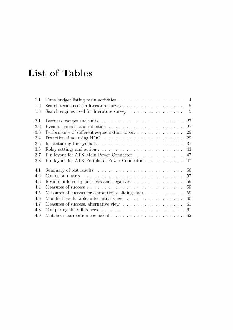
List of Tables
1.1 Time budget listing main activities . . . . . . . . . . . . . . . . . . 41.2 Search terms used in literature survey . . . . . . . . . . . . . . . . . 51.3 Search engines used for literature survey . . . . . . . . . . . . . . . 5
3.1 Features, ranges and units . . . . . . . . . . . . . . . . . . . . . . . 273.2 Events, symbols and intention . . . . . . . . . . . . . . . . . . . . . 273.3 Performance of different segmentation tools . . . . . . . . . . . . . . 293.4 Detection time, using HOG . . . . . . . . . . . . . . . . . . . . . . 293.5 Instantiating the symbols . . . . . . . . . . . . . . . . . . . . . . . . 373.6 Relay settings and action . . . . . . . . . . . . . . . . . . . . . . . . 433.7 Pin layout for ATX Main Power Connector . . . . . . . . . . . . . . 473.8 Pin layout for ATX Peripheral Power Connector . . . . . . . . . . . 47
4.1 Summary of test results . . . . . . . . . . . . . . . . . . . . . . . . 564.2 Confusion matrix . . . . . . . . . . . . . . . . . . . . . . . . . . . . 574.3 Results ordered by positives and negatives . . . . . . . . . . . . . . 594.4 Measures of success . . . . . . . . . . . . . . . . . . . . . . . . . . . 594.5 Measures of success for a traditional sliding door . . . . . . . . . . . 594.6 Modified result table, alternative view . . . . . . . . . . . . . . . . 604.7 Measures of success, alternative view . . . . . . . . . . . . . . . . . 614.8 Comparing the differences . . . . . . . . . . . . . . . . . . . . . . . 614.9 Matthews correlation coefficient . . . . . . . . . . . . . . . . . . . . 62

ii
“report” — 2011/6/20 — 15:25 — page xiv — #14 ii
ii
ii
xiv List of Tables

ii
“report” — 2011/6/20 — 15:25 — page 1 — #15 ii
ii
ii
Chapter 1
Introduction and Overview
Figure 1.1: Automatic doors (http://xkcd.com/175)
In the following sections the background and motivation for this project isdescribed. I define the goals and research questions for the work. I also provide adescription of the research method used in the project work. Finally I present anoverview of the report structure; the chapters and their content.
1.1 Background and Motivation
The background for this project is my master’s project within the field of ArtificialIntelligence at the Norwegian University of Science and Technology.

ii
“report” — 2011/6/20 — 15:25 — page 2 — #16 ii
ii
ii
2 Goals and Research Questions
The main motivation for the work is given in the article by Kofod-Petersenet al. (2009). This article points out the weaknesses of today’s automated slidingdoors in the context of ambient intelligent systems, and outlines the challengesof interpreting human intentions. Although the sliding doors are not the mainconcern, they point out the miscommunication between the two actors, humanand computer. Sliding doors provide a simple case with a limited set of actionsand make a great starting point for further work.
Can an automated sliding door respond to the user’s intention? This challengetouches multiple areas: It requires a complete domain model of human behavior,describing the user’s movement. Further, it requires data collection and featureextraction together with an inference mechanism for intentions.
Reasoning over intentions based on behavior requires work on the symboliclevel, rather than the more common sub-symbolic level. Lifting the process to thislevel generalizes the process, giving a result that can be transferred more easily toother similar tasks.
Another motivational factor for this thesis is the work that was done in myspecialization project. This project laid the foundations, by exploring the possi-bilities within the challenge. I now take the previous results further, and try tosolve this task completely – with a functional door. Building an intelligent slidingdoor that might actually work, is in itself a motivation. This factor also includesthe motivation for working with an actual door instead of simulating one. Using areal door alleviates some of the issues that arise when simulating human behavior.In order to evaluate a solution it is important to work with behavior that is asclose to reality as possible, showing true, unaffected intentions.
1.2 Goals and Research Questions
Goal 1 Design a model of features, human behavior and intentions.
Define a set of features needed in order to describe human behavior in thecontext of a door. Quantify the features, in a manner that the model issuitable both for feature extraction and intentional reasoning.
Goal 2 Design a mechanism for capturing and extracting features according tothe model.
Do a study in Computer Vision in order to find the required componentsand suitable tools for capturing and extracting the features as described inGoal 1.
Goal 3 Design a reasoning mechanism for inference of intention.
ii
“report” — 2011/6/20 — 15:25 — page 3 — #17 ii
ii
ii
Introduction and Overview 3
Do a study within AI1 theory in order to find a mechanism able to make thedecision about opening a door, based on the type of features as describedin Goal 1. The mechanism must be able to draw conclusions regarding theintentions of the person interacting with the door.
Goal 4 Implement software comprising the results from Goal 1, 2 and 3
Develop a complete software application for the operation of a door equippedwith sensors giving it the ability to reason.
Goal 5 Build a motorized sliding door
Build a door that can be operated by a computer running the developedsoftware.
Research question 1 What set of computer vision algorithms will meet Goal 2efficiently?
Evaluate different algorithms in order to find a combination that performswell enough for real-time performance.
Research question 2 What is a well suited reasoning mechanism for this task?
Evaluate the different mechanisms found in Goal 3, in order to find the onewith best accuracy regarding the actual intentions of a person in front of adoor.
1.3 Contributions
The 11th Scandinavian Conference on Artificial Intelligence was held during mythesis work. I participated in this conference with a poster and a demonstrationof the door. The poster can be seen in Appendix D.
1.4 Research Method
The work done in this project can be divided into seven stages. The stages aredescribed in the following list.
Problem overview In this stage I worked on the problem description, definingthe problem area; what would be included and what would not be included. Ihad meetings with my supervisor Anders Kofod-Petersen, where we discussedthe contents of the work in context of the specialization project and the

ii
“report” — 2011/6/20 — 15:25 — page 4 — #18 ii
ii
ii
4 Research Method
Table 1.1: Time budget listing main activities
Week Date Activity3 17. Jan Planning4 24. Jan ”5 31. Jan Build door6 7. Feb ”7 14. Feb ”8 21. Feb Computer Vision9 28. Feb ”10 7. Mar ”11 14. Mar ”12 21. Mar Reasoning/Decision13 28. Mar ”14 4. Apr ”15 11. Apr Testing16 18. Apr ”17 25. Apr Easter vacation18 2. May Testing19 9. May Report writing20 16. May ”21 23. May ”22 30. May ”23 6. June Extra24 13. June Extra (application needed).

ii
“report” — 2011/6/20 — 15:25 — page 5 — #19 ii
ii
ii
Introduction and Overview 5
previous work done through that project. I worked out a time budget, givinga rough overview of main activities (see Table 1.1).
During the project, I revised the time budget several times, as additionalactivities were needed and some of the activities took longer than initiallyplanned.
Literature survey This stage was mainly performed in the specialization project,where we did a research on similar problems, existing works and projects.For this purpose we made a table of search terms (see Table 1.2) relevant tothe project, dividing it into categories corresponding to the parts as definedin the previous stage. We ran different combinations of these search termsin several digital libraries (listed in Table 1.3). Different combinations gavedifferent levels of quality and relevancy in search results.
Table 1.2: Search terms used in literature survey
Sensor Computer Vision Model/Reasoning Human Behaviorstereo vision stereo vision knowledge base intentioncamera motion detection learning movementmotion sensor segmentation reasoning anatomysensor fusion kalman filter retrieval body language
facial recognition decision posturevector semiotics hipproximity syntax posemarker-less semantic body alignmentmotion tracking gaze
gaze directionhuman behavior
kinect hog jointhistogram of oriented gradientsgpubody tracking
Table 1.3: Search engines used for literature survey
Search engine URLIEEE Xplore http://ieeexplore.ieee.org
SpringerLink http://www.springerlink.com
ISI Web of Knowledge http://www.isiknowledge.com
ScienceDirect http://www.sciencedirect.com
To determine the relevancy of the resources, we looked at the search resultsas follows:
1AI is an abbreviation for artificial intelligence.
ii
“report” — 2011/6/20 — 15:25 — page 6 — #20 ii
ii
ii
6 Research Method
1. Title – If irrelevant, discard. If relevant, go to step 2.
2. Abstract – If irrelevant, discard. If relevant, go to step 3.
3. Overview – Read quickly through the article, if irrelevant, discard. Ifrelevant, go to step 4.
4. Catalog – Read through article, save in database, comment and rateaccording to relevancy and usefulness.
It was necessary to expand the table of search terms in order to update it to thefocus areas of the master project. This can be seen in the lower row of the table.
Component research and evaluation This stage was performed for all of themain parts of the project: computer vision, modeling and reasoning. Theresearch results from the specialization project narrowed down the searchfield, and this stage was now mainly about evaluating the previous findingsas well as choosing the technologies and mechanisms to use.
Implementation This stage involved the production of the complete system. Itwas not a separate work stage, but continued throughout the span of theproject.
Work that belongs to this stage includes:
• Building a sliding door
• Building a door controller
• Building an intention-aware door operator
– Modeling human behavior
– Programming a human tracking mechanism
– Programming a reasoning mechanism
Testing and evaluation The door was tested using multiple test subjects, in-structed to interact in various ways with the door. Since this stage includedmonitoring third party people using cameras, it was necessary to contactNSD concerning privacy and the handling of personal data (see Section 3.4.2,page 49). The collected data was evaluated using standard performance mea-sures.
Thesis writing This process occurred throughout the time span of the project,but was concentrated mostly in the end. Here I documented the work thatwas done, together with theory and background. The written material fromother stages was revised and structured.
Meetings I had regular contact with my supervisor. In these meetings I gave anoverview of the work being done, and got feedback and input for the workahead.
ii
“report” — 2011/6/20 — 15:25 — page 7 — #21 ii
ii
ii
Introduction and Overview 7
1.5 Thesis Structure
The goal of this master’s thesis is to document the work done in my master’sproject. The reader is introduced to a problem concerning the interaction betweenhuman beings and non-human actors in their environment. I then proceed witha presentation of the theory and background required to get an understanding ofthis problem and point out a solution. Further I describe my proposed solutionand evaluate it.
The thesis is structured in chapters. Chapter 1 (this chapter) gives an intro-duction to the project, describing the background, motivation and goals. It alsoexplains the work methods. Chapter 2 presents the context of the problem, andprovides background and theory according to the different parts of the project.Chapter 3 describes the results of my work. It explains decisions and choices, aswell as giving details about each of the solution components. Chapter 4 shows howthe results were tested and evaluated. It also sums up the project with a discussionand summary. Finally I describe future work; things that can be improved andideas for others to pick up. A Bibliography lists the sources referred throughoutthe thesis. In the back, Appendices provide details and material that were left outof the main contents.

ii
“report” — 2011/6/20 — 15:25 — page 8 — #22 ii
ii
ii
8 Thesis Structure
ii
“report” — 2011/6/20 — 15:25 — page 9 — #23 ii
ii
ii
Chapter 2
Theory and Background
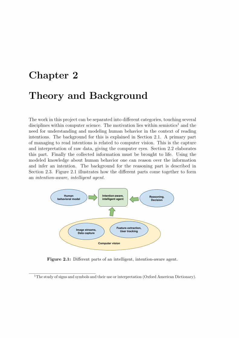
The work in this project can be separated into different categories, touching severaldisciplines within computer science. The motivation lies within semiotics1 and theneed for understanding and modeling human behavior in the context of readingintentions. The background for this is explained in Section 2.1. A primary partof managing to read intentions is related to computer vision. This is the captureand interpretation of raw data, giving the computer eyes. Section 2.2 elaboratesthis part. Finally the collected information must be brought to life. Using themodeled knowledge about human behavior one can reason over the informationand infer an intention. The background for the reasoning part is described inSection 2.3. Figure 2.1 illustrates how the different parts come together to forman intention-aware, intelligent agent.
Reasoning,Decision
Human behavioral model
Image streams,Data capture
Feature extraction,User tracking
Intention-aware,intelligent agent
Computer vision
Figure 2.1: Different parts of an intelligent, intention-aware agent.
1The study of signs and symbols and their use or interpretation (Oxford American Dictionary).
ii
“report” — 2011/6/20 — 15:25 — page 10 — #24 ii
ii
ii
10 Human Behavior and Intention
2.1 Human Behavior and Intention
An intelligent door must understand the intentions of human beings in order toknow if it should open or not. Understanding the intentions of humans is byno means a trivial task. Human behavior can be complex, and sometimes evenirrational. A person walking towards a door can suddenly change to standing still,reading the newspaper in the newspaper stand beside the door. Perhaps the standwas the intended destination all along and not the door. Then again, the doorcould have been the initial target, but the front page of the newspaper made theperson change his mind.
Martinec (2001) has done research on resources of movement focusing on in-terpersonal relations. He describes a model for actions, using parameters likebody angle and distance. He also describes sign functions, mapping movementsto meaning. His work can be used for developing a framework for interpretingbody language. The work is based on previous work by Hall, following conceptsposed by Halliday. Moore (2008) extends the works of Martinec by describing acontext dependency, stating that the values (like distance and angle) valid for onecontext may not be valid for another context, using surgery as a point of reference.Guerra-Filho and Aloimonos (2006) take another approach, presenting a HumanActivity Language (HAL) for symbolic non-arbitrary representation of visual andmotor information. This language is based on the empirical discovery of a lin-guistic framework for the human action space. The described space has its ownphonemes, morphemes and sentences. This approach uses learning algorithms forthe different actions. Yet another approach is proposed by Amano et al. (2005).Here we are presented with a linguistic representation of human motion, basedon the knowledge representation scheme proposed in The Mental Image DirectedSemantic Theory (MIDST). A formal language is defined, with syntax and seman-tics. The suggested application is interpretation of human motion data from amotion capture system. The movements in this approach is described with Lo-cus formulas. The approaches made by Guerra-Filho and Aloimonos and Amanoet al. are similar, but while the latter one initially requires a full description ofthe modeled actions, the first one uses learning algorithms.
2.1.1 Model
One of the goals for the project is to lift the reasoning process from a sub-symbolicto a symbolic level. This implies an abstraction of the pixel stream from thecameras into symbols like position and speed. The symbols to use in this case arefeatures extracted from the image stream.
The features that can be extracted from one single image stream are numerous.Adding an additional camera or sensor device gives even more possibilities. Some
ii
“report” — 2011/6/20 — 15:25 — page 11 — #25 ii
ii
ii
Theory and Background 11
of the features are more suited than others, and Kofod-Petersen et al. (2009)suggest the use of body alignment, proximity and visual target as features ofhuman behavior suited for modeling intention. The latter one is later discardedas being of low value concerning intention.
The body alignment feature is divided into two features, the orientation of theshoulders (shoulder angle) and the hips (hip angle), where the measured anglesare relative to a point of origin. This point will be the door in most of the cases,but can also include other people, when more than one person is captured by thecameras.
The proximity feature gives a measure of closeness to the door. When addingthe perspective of time, this feature can be used to extract another feature, mo-tion. This is useful in distinguishing between people moving towards the door andmoving away from the door. We now have the full model of features suggested byKofod-Petersen et al. (2009) as shown in Figure 2.2.
Figure 2.2: Features for modeling intention (from Kofod-Petersen et al., 2009)
The features described here are components of the perceived intention. If wehave these features, we can derive a conclusion concerning the user’s intentions.
2.2 Computer Vision
There has been much research into the low-level processing of image data. As aresult of this, there are several different ways of segmenting and extracting featuresfrom various image sources.
ii
“report” — 2011/6/20 — 15:25 — page 12 — #26 ii
ii
ii
12 Computer Vision
Computer vision is the science and technology of machines that see, where seein this case means that the machine is able to extract information from an imagethat is necessary to solve some task (Sonka et al., 2008).
The detection and tracking of humans are simple tasks for humans, but difficultfor a computer for a variety of reasons. The human body can be morphed into manydifferent poses, be clothed in a myriad of different clothes and carry accessories.All this comes in addition to the problem with the scenery, weather and lightingconditions in which to do the detection.
In the works of Giosan et al. (2009) we can see the use of stereo vision in marker-less pedestrian detection. This system uses full body contours when detectinghumans. A result of this is that the human model used for comparison is a libraryof contours derived from many different poses. The use of stereo vision enables itto extract 3D information from the captured data, and this information is usedin combination with simple 2D edge detection to provide better results regardingforeground/background separation.
Caillette and Howard (2004) use a different strategy in which 3D models areextracted. This is achieved using several cameras capturing an object, in this casea human, and running calculations on the captured images. It produces a 3D voxelrepresentation which is then matched to a kinematic representation in the same 3Dspace. Because of this kinematic model that has to fit to the object, the trackingcan be very accurate, but it requires the system to know the model beforehand.
A 3D representation is also used by Corazza et al. (2007). In this system theycreate the 3D representation by using the technique visual hull.
Another somewhat different approach to the human detection and trackingtask is made by Viola and Jones (2001) where a rapid object detector is proposedusing a boosted cascade of simple features. This solution uses Haar-like featuresand is specially useful for face detection. Further improvements to this has beendone by Lienhart and Maydt (2002) strengthening rotational concerns.
Dalal and Triggs (2005) present a detector using Histograms of Oriented Gradi-ents (HOG). It improves the accuracy of object detection, specially when it comesto pedestrians.
Further improvements have been suggested lately (Zhu et al., 2006; Jia andZhang, 2007), trying to combine the discriminative power of HOG features (Dalaland Triggs, 2005) with the real-time performance of Viola’s face detection frame-work (Viola and Jones, 2001). Work has also been done trying to boost the perfor-mance of the algorithm using the computer’s GPU2 (Lillywhite et al., 2009; Bilgicet al., 2010; Sugano et al., 2010).
2Graphics Processing Unit
ii
“report” — 2011/6/20 — 15:25 — page 13 — #27 ii
ii
ii
Theory and Background 13
2.2.1 Computer Vision Tools
Early studies pointed out stereo vision as a useful tool. This is basically due tothe requirement of measuring distances to key points of the objects being tracked.
A stereo vision setup would use two cameras. They would be placed abovethe door, and be separated horizontally to give a base-line for the triangulationfrom which a distance can be calculated. The process, as explained by Sonka et al.(2008), is to find the coordinates in the two images of the “corresponding points”.These are the two representations of easily identifiable structures in the real worldsuch as corners found by the Moravec operator (Sonka et al., 2008).
The arrangement of the cameras, together with the disparity in the coordinatepositions, allows the distance to be calculated. The equations are often over-determined and are solved using the SVD method3, to give a least square errorsolution. The stereo vision is a module of the system that gives a distance image.This could be replaced by a different method if a suitable device becomes available.
There are several stages in the data collection pipeline. The first being theactual image capturing done with simple cameras. Second, the images must besegmented, separating the regions of interest from the rest. Following this, featureshave to be extracted and finally converted to symbols. This is as we can see, atask of getting from a sub-symbolic level to a symbolic level which is non-trivial(Sonka et al., 2008).
Segmentation
Segmentation is the process of associating names from the outside world withcollections of pixels. Segmentation is also a pattern recognition task: separatingparts of the image that are of interest for further analysis from those that arenot; often termed foreground and background. Segmentation is tuned to suit thegoal of the system and is conditioned to tolerate data that is expected from theapplication domain.
The system for the sliding doors will receive image data that is rather unstablebecause of shadowing as people move about and automatic parameter changesin the camera. There is also a requirement to segment images to support anacceptable frame rate.
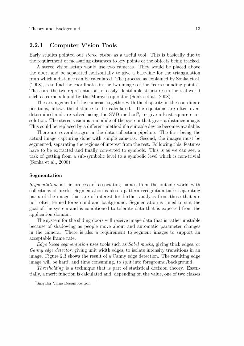
Edge based segmentation uses tools such as Sobel masks, giving thick edges, orCanny edge detector, giving unit width edges, to isolate intensity transitions in animage. Figure 2.3 shows the result of a Canny edge detection. The resulting edgeimage will be hard, and time consuming, to split into foreground/background.
Thresholding is a technique that is part of statistical decision theory. Essen-tially, a merit function is calculated and, depending on the value, one of two classes
3Singular Value Decomposition
ii
“report” — 2011/6/20 — 15:25 — page 14 — #28 ii
ii
ii
14 Computer Vision
Figure 2.3: Application of Canny
is chosen. The effectiveness of the method depends on the merit function and howmuch information it uses. The more complicated the function, then the slower thesegmentation will run.
The simplest approach is to use the pixel value as the merit function and tochoose a threshold value from the image statistics. Simple thresholding uses athreshold that is a local minimum in the image histogram. The choice is easiestwhen the histogram is clearly bi-modal, but this is no guarantee of good perfor-mance.
Preliminary experiments showed that images of people near the door containeda wide range of intensities and that a separation between foreground and back-ground was probably going to be complicated.
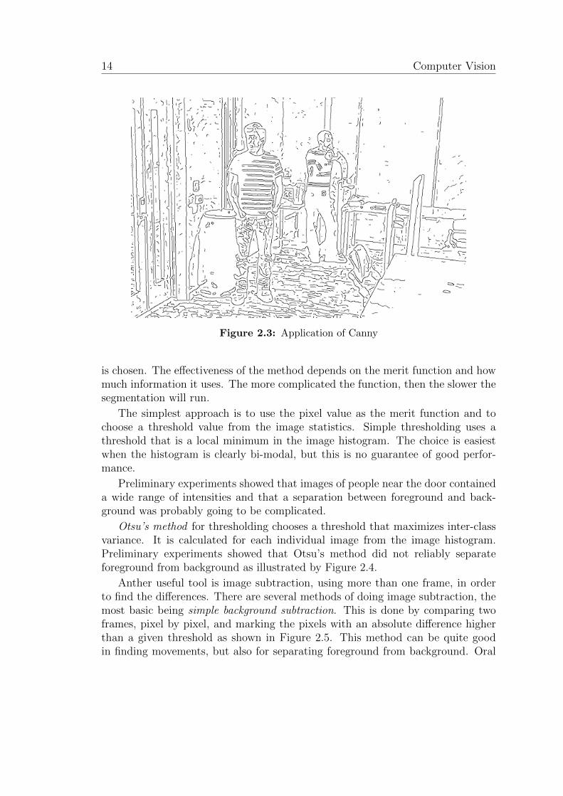
Otsu’s method for thresholding chooses a threshold that maximizes inter-classvariance. It is calculated for each individual image from the image histogram.Preliminary experiments showed that Otsu’s method did not reliably separateforeground from background as illustrated by Figure 2.4.
Anther useful tool is image subtraction, using more than one frame, in orderto find the differences. There are several methods of doing image subtraction, themost basic being simple background subtraction. This is done by comparing twoframes, pixel by pixel, and marking the pixels with an absolute difference higherthan a given threshold as shown in Figure 2.5. This method can be quite goodin finding movements, but also for separating foreground from background. Oral
ii
“report” — 2011/6/20 — 15:25 — page 15 — #29 ii
ii
ii
Theory and Background 15
and Deniz (2007) compare several image subtraction methods with the purpose ofdiscovering movement.
As described initially, there are other alternatives to the segmentation problem.One of the choices is to use an object recognizer. This might be seen as a bridgebetween the segmentation and feature extraction process. By using a trainedHOG descriptor (explained in detail in the following section) the system can detectpeople in a given frame. This will provide bounding boxes in which there ideallywill be one person. The focus can then be on these boxes for further analysis.
Figure 2.4: Application of Otsu: From left to right; original, gray scale and Otsuapplied.
Figure 2.5: Application of image subtraction: From left to right; background, back-ground+foreground and difference mask
ii
“report” — 2011/6/20 — 15:25 — page 16 — #30 ii
ii
ii
16 Computer Vision
Histogram of Oriented Gradients Descriptors
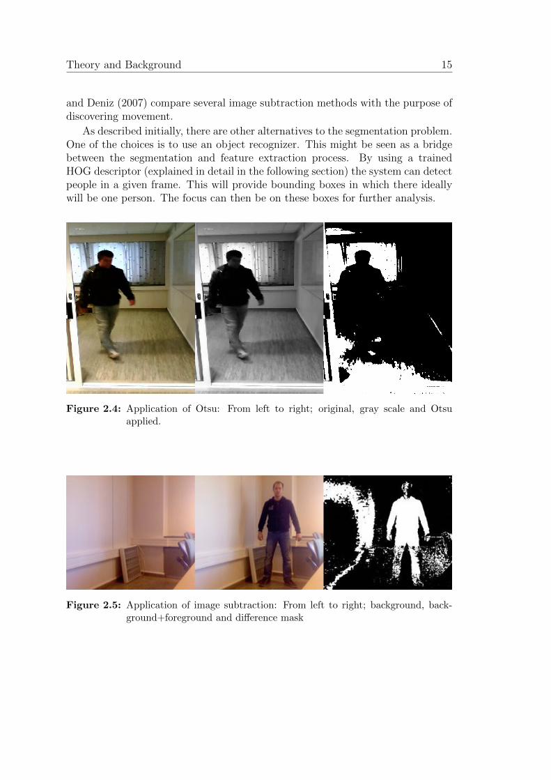
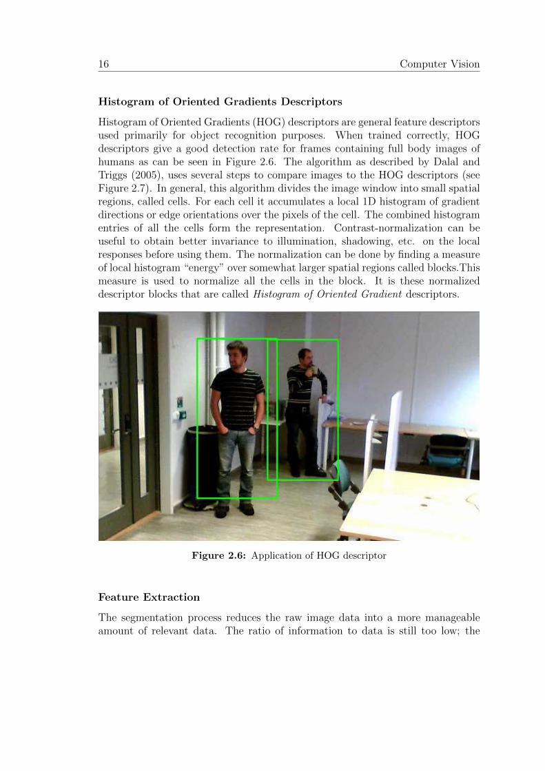
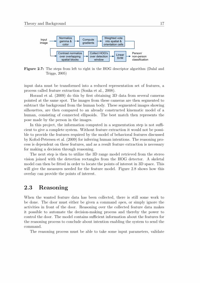
Histogram of Oriented Gradients (HOG) descriptors are general feature descriptorsused primarily for object recognition purposes. When trained correctly, HOGdescriptors give a good detection rate for frames containing full body images ofhumans as can be seen in Figure 2.6. The algorithm as described by Dalal andTriggs (2005), uses several steps to compare images to the HOG descriptors (seeFigure 2.7). In general, this algorithm divides the image window into small spatialregions, called cells. For each cell it accumulates a local 1D histogram of gradientdirections or edge orientations over the pixels of the cell. The combined histogramentries of all the cells form the representation. Contrast-normalization can beuseful to obtain better invariance to illumination, shadowing, etc. on the localresponses before using them. The normalization can be done by finding a measureof local histogram “energy” over somewhat larger spatial regions called blocks.Thismeasure is used to normalize all the cells in the block. It is these normalizeddescriptor blocks that are called Histogram of Oriented Gradient descriptors.
Figure 2.6: Application of HOG descriptor
Feature Extraction
The segmentation process reduces the raw image data into a more manageableamount of relevant data. The ratio of information to data is still too low; the
ii
“report” — 2011/6/20 — 15:25 — page 17 — #31 ii
ii
ii
Theory and Background 17
Input image
Normalize gamma &
color
Compute gradients
Weighted vote into spatial &
orientation cells
Contrast normalize over overlapping
spatial blocks
Collect HOG's over detection
window
Linear SVM
Person/non-personclassification
Figure 2.7: The steps from left to right in the HOG descriptor algorithm (Dalal andTriggs, 2005)
input data must be transformed into a reduced representation set of features, aprocess called feature extraction (Sonka et al., 2008).
Horaud et al. (2009) do this by first obtaining 3D data from several cameraspointed at the same spot. The images from these cameras are then segmented tosubtract the background from the human body. These segmented images showingsilhouettes, are then compared to an already constructed kinematic model of ahuman, consisting of connected ellipsoids. The best match then represents thepose made by the person in the images.
In this project, the information computed in a segmentation step is not suffi-cient to give a complete system. Without feature extraction it would not be possi-ble to provide the features required by the model of behavioral features discussedby Kofod-Petersen et al. (2009) for inferring human intentions. The reasoning pro-cess is dependent on these features, and as a result feature extraction is necessaryfor making a decision through reasoning.
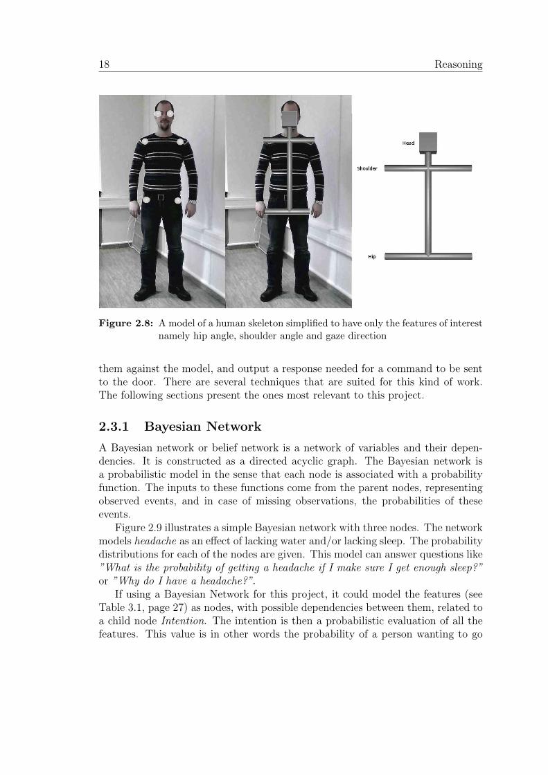
The next step is then to utilize the 3D range model retrieved from the stereovision joined with the detection rectangles from the HOG detector. A skeletalmodel can then be fitted in order to locate the points of interest in 3D space. Thiswill give the measures needed for the feature model. Figure 2.8 shows how thisoverlay can provide the points of interest.
2.3 Reasoning
When the wanted feature data has been collected, there is still some work tobe done. The door must either be given a command open, or simply ignore theactivities in front of the door. Reasoning over the collected feature data makesit possible to automate the decision-making process and thereby the power tocontrol the door. The model contains sufficient information about the features forthe reasoning process to conclude about intention enabling the system to send thecommand.
The reasoning process must be able to take some input parameters, validate
ii
“report” — 2011/6/20 — 15:25 — page 18 — #32 ii
ii
ii
18 Reasoning
Figure 2.8: A model of a human skeleton simplified to have only the features of interestnamely hip angle, shoulder angle and gaze direction
them against the model, and output a response needed for a command to be sentto the door. There are several techniques that are suited for this kind of work.The following sections present the ones most relevant to this project.
2.3.1 Bayesian Network
A Bayesian network or belief network is a network of variables and their depen-dencies. It is constructed as a directed acyclic graph. The Bayesian network isa probabilistic model in the sense that each node is associated with a probabilityfunction. The inputs to these functions come from the parent nodes, representingobserved events, and in case of missing observations, the probabilities of theseevents.
Figure 2.9 illustrates a simple Bayesian network with three nodes. The networkmodels headache as an effect of lacking water and/or lacking sleep. The probabilitydistributions for each of the nodes are given. This model can answer questions like”What is the probability of getting a headache if I make sure I get enough sleep?”or ”Why do I have a headache?”.
If using a Bayesian Network for this project, it could model the features (seeTable 3.1, page 27) as nodes, with possible dependencies between them, related toa child node Intention. The intention is then a probabilistic evaluation of all thefeatures. This value is in other words the probability of a person wanting to go

ii
“report” — 2011/6/20 — 15:25 — page 19 — #33 ii
ii
ii
Theory and Background 19
Headache (H)
Lack of sleep (S)Lack of water (W)
P(W)
f
0.60
0.40
tP(S)
f
0.60
0.40
t
0.25tt
0.15ft
0.10tf
0.02ff
P(H)SW
Figure 2.9: A simple Bayesian network
through the door. If it is higher than a set threshold the door can be opened, ifnot, leave it closed.
A challenge related to this approach would be to define accurate possibilities foreach event. It is crucial to get a correct and close-to-reality model when dealingwith the hard-to-observe intentions of human beings. The possibilities for thedifferent states leading to an intention can not easily be derived from my model ofbehavior (see Section 3.1, page 25), making this approach less desirable.
2.3.2 Decision Network
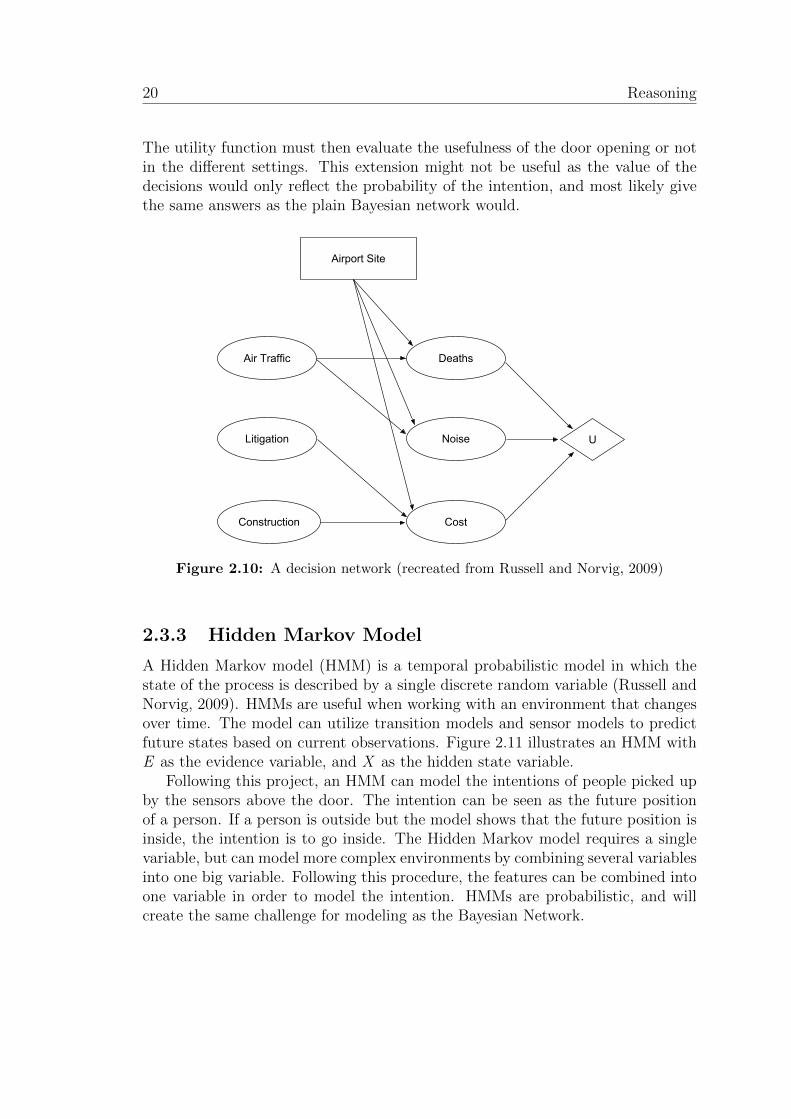
When making decisions, a useful tool can be decision networks4. This is a gen-eral mechanism for making rational decisions, following the principle of maximumexpected utility (Russell and Norvig, 2009). The decision network is similar to aBayesian network, but includes extra nodes for actions and utilities. The chancenodes (oval) represent the random variables, like in the Bayesian network. Thedecision nodes (rectangle) represent the choices to be made. The utility nodes(diamond) represent the utility function that describes the value of the resultsfrom a decision. The choices made can influence different parts of the network.By describing the utility of different states, it is possible to choose the decisionthat maximizes the utility.
Figure 2.10 shows how the choice of an Airport Site influences deaths, noise andcost. This influence is based on the nodes Air Traffic, Litigation and Construction.The utility node takes the deaths, noise and cost in consideration to conclude aboutthe best Airport Site.
For this project the network would be the same as the Bayesian network, theonly difference being the addition of a decision node OpenDoor and a utility node.
4Also known as influence diagrams
ii
“report” — 2011/6/20 — 15:25 — page 20 — #34 ii
ii
ii
20 Reasoning
The utility function must then evaluate the usefulness of the door opening or notin the different settings. This extension might not be useful as the value of thedecisions would only reflect the probability of the intention, and most likely givethe same answers as the plain Bayesian network would.
Air Traffic
Litigation
Construction
Deaths
Noise
Cost
Airport Site
U
Figure 2.10: A decision network (recreated from Russell and Norvig, 2009)
2.3.3 Hidden Markov Model
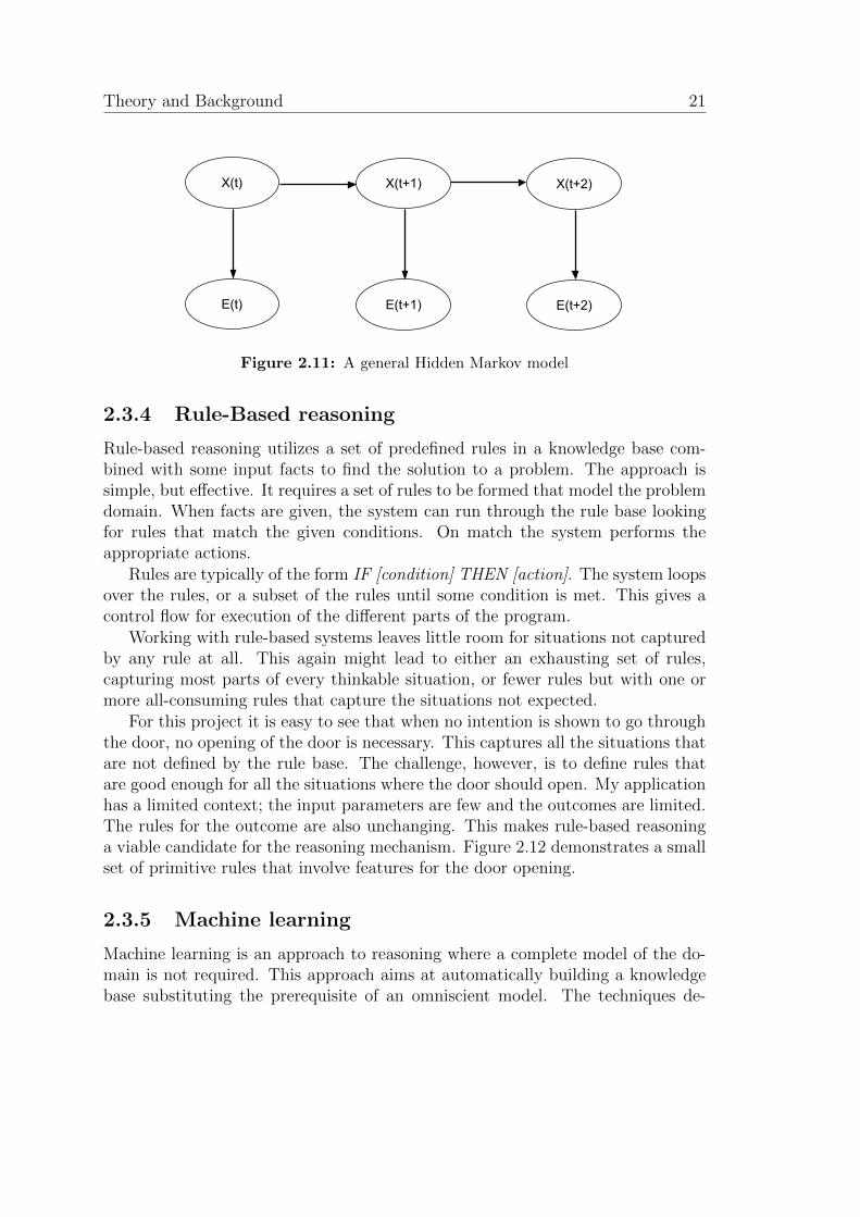
A Hidden Markov model (HMM) is a temporal probabilistic model in which thestate of the process is described by a single discrete random variable (Russell andNorvig, 2009). HMMs are useful when working with an environment that changesover time. The model can utilize transition models and sensor models to predictfuture states based on current observations. Figure 2.11 illustrates an HMM withE as the evidence variable, and X as the hidden state variable.
Following this project, an HMM can model the intentions of people picked upby the sensors above the door. The intention can be seen as the future positionof a person. If a person is outside but the model shows that the future position isinside, the intention is to go inside. The Hidden Markov model requires a singlevariable, but can model more complex environments by combining several variablesinto one big variable. Following this procedure, the features can be combined intoone variable in order to model the intention. HMMs are probabilistic, and willcreate the same challenge for modeling as the Bayesian Network.
ii
“report” — 2011/6/20 — 15:25 — page 21 — #35 ii
ii
ii
Theory and Background 21
X(t)
E(t)
X(t+1)
E(t+1)
X(t+2)
E(t+2)
Figure 2.11: A general Hidden Markov model
2.3.4 Rule-Based reasoning
Rule-based reasoning utilizes a set of predefined rules in a knowledge base com-bined with some input facts to find the solution to a problem. The approach issimple, but effective. It requires a set of rules to be formed that model the problemdomain. When facts are given, the system can run through the rule base lookingfor rules that match the given conditions. On match the system performs theappropriate actions.
Rules are typically of the form IF [condition] THEN [action]. The system loopsover the rules, or a subset of the rules until some condition is met. This gives acontrol flow for execution of the different parts of the program.
Working with rule-based systems leaves little room for situations not capturedby any rule at all. This again might lead to either an exhausting set of rules,capturing most parts of every thinkable situation, or fewer rules but with one ormore all-consuming rules that capture the situations not expected.
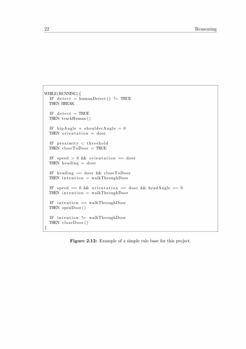
For this project it is easy to see that when no intention is shown to go throughthe door, no opening of the door is necessary. This captures all the situations thatare not defined by the rule base. The challenge, however, is to define rules thatare good enough for all the situations where the door should open. My applicationhas a limited context; the input parameters are few and the outcomes are limited.The rules for the outcome are also unchanging. This makes rule-based reasoninga viable candidate for the reasoning mechanism. Figure 2.12 demonstrates a smallset of primitive rules that involve features for the door opening.
2.3.5 Machine learning
Machine learning is an approach to reasoning where a complete model of the do-main is not required. This approach aims at automatically building a knowledgebase substituting the prerequisite of an omniscient model. The techniques de-
ii
“report” — 2011/6/20 — 15:25 — page 22 — #36 ii
ii
ii
22 Reasoning
WHILE(RUNNING)IF de t e c t = humanDetect ( ) != TRUETHEN BREAK
IF dete c t = TRUETHEN trackHuman ( )
IF hipAngle + shoulderAngle = 0THEN o r i e n t a t i o n = door
IF proximity < th r e sho ldTHEN closeToDoor = TRUE
IF speed > 0 && o r i e n t a t i o n == doorTHEN heading = door
IF heading == door && closeToDoorTHEN i n t e n t i o n = walkThroughDoor
IF speed == 0 && o r i e n t a t i o n == door && headAngle == 0THEN i n t e n t i o n = walkThroughDoor
IF i n t e n t i o n == walkThroughDoorTHEN openDoor ( )
IF i n t e n t i o n != walkThroughDoorTHEN closeDoor ( )
Figure 2.12: Example of a simple rule base for this project.
ii
“report” — 2011/6/20 — 15:25 — page 23 — #37 ii
ii
ii
Theory and Background 23
scribed in this section are not what I primarily aim for in the project goals, butthey will serve as a perspective of alternative approaches subject to future workfor the reason of comparison. Machine learning can be divided into three cases:supervised, unsupervised and reinforcement learning (Russell and Norvig, 2009).Supervised learning requires someone or something giving feedback about the out-come of a choice. Unsupervised learning is learning in the case of lacking output,hence no feedback. Reinforcement learning is learning based on reinforcementsrather than being told what to do. The reinforcements can be seen as rewards ofdifferent sizes given according to the choices made.
In the sliding door case, there are some domain knowledge, and the possibilityof telling the agent what is right and wrong. The task of learning from scratchwithout feedback, would be impossible, since the door’s only action is to openor not to open. No knowledge about when to open, results in the door alwaysbeing closed5. Since the door must be automated, the learning is better done in atraining process, where the cases are classified by intentions (want to enter, doesnot want to enter).
Decision Tree Learning
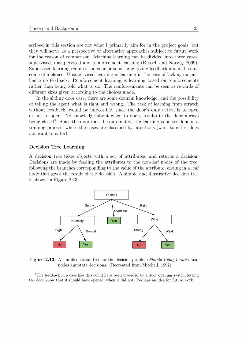
A decision tree takes objects with a set of attributes, and returns a decision.Decisions are made by feeding the attributes to the non-leaf nodes of the tree,following the branches corresponding to the value of the attribute, ending in a leafnode that gives the result of the decision. A simple and illustrative decision treeis shown in Figure 2.13.
Outlook
Sunny
Wind
Rain
Yes
Strong
No
Humidity
High
Overcast
Normal
Yes
No Yes
Weak
Figure 2.13: A simple decision tree for the decision problem Should I play tennis; Leafnodes annotate decisions. (Recreated from Mitchell, 1997)
5The feedback in a case like this could have been provided by a door opening switch, lettingthe door know that it should have opened, when it did not. Perhaps an idea for future work.
ii
“report” — 2011/6/20 — 15:25 — page 24 — #38 ii
ii
ii
24 Reasoning
Learning in the decision tree is mainly a classification problem. A set of trainingdata must be used where the correct decision is supplied. Then, following a decisiontree learning algorithm, a tree can be built that classifies the training data.
The challenges in this approach is handling noise (decisions based on irrelevantattributes) and overfitting (over-specified tree not addressing new cases). Good,representative training data, together with a well developed decision tree learningalgorithm provide a robust decision tree, allowing for qualified decisions. A decisiontree can be transformed into a rule set, and is in this way similar to the rule-basedreasoning, where the main difference is the learning process.
Case-Based Reasoning
Case-based reasoning (CBR) is a method for problem solving and learning. Ac-cording to Aamodt and Plaza (1994) CBR is “to solve a new problem by remem-bering a previous similar situation and by reusing information and knowledge ofthat situation”. The method can be divided into four main steps: Retrieve, Reuse,Revise and Retain (Aamodt and Plaza, 1994).
The four steps of CBR:
• Retrieve the most similar problems from the case-base
• Reuse the solutions that are applicable
• Revise the suggested solution
• Retain the new problem/solution for later use
This is a strong and adaptive technique, with its strength in the continuous buildof a growing knowledge base. For the reasoning problem in this project, this mightnot be the best approach. With few methods of providing continuous feedback, itis better with a more static learning phase.
ii
“report” — 2011/6/20 — 15:25 — page 25 — #39 ii
ii
ii
Chapter 3
Research Results
3.1 Modeling human behavior
The model of human behavior is the basis for the rest of the work. This modelguides the data capturing process, defining the features to produce. It also providesthe foundation for the rules in reasoning engine. Without a strong, precise model,it is unclear which data that is useful to collect, and furthermore the reasoningengine will have no knowledge about human behavior and intentions.
The work of building the model mapping the features to intentions, is based onthe model suggested by Kofod-Petersen et al. (2009) and described in Section 2.1.1(page 10). The previous work gives a starting point, but I need some furtherspecifications of this model, in order to make it fit to the problem. When writingabout intentions I will refer to the intention of walking through the door as apositive intention and the intention of not walking through the door as a negativeintention.
3.1.1 Motion
Motion can be divided into more features. I suggest speed, acceleration and head-ing. Speed can be used to determine if a person is moving or not. Acceleration canbe useful for predicting future motion, like slowing down for stopping and speed-ing up for leaving. Heading, or direction of movement, is obvious and necessary inorder to read the intention of people.
The motion feature, with its specifications, requires a perspective of time. Asingle captured frame will only give parts of the information needed, thus a se-quence of frames is required. As a result of this, a tracking mechanism is neededthat follows the subjects in front of the door over time.

ii
“report” — 2011/6/20 — 15:25 — page 26 — #40 ii
ii
ii
26 Modeling human behavior
3.1.2 Proximity
Proximity is a simple feature defining the distance between the door and the user.Regardless of its simplicity, this measure is one of the most important in themodel. A user that is far away from the door can easily be ignored, until thedistance is shorter. The door should not open before it is necessary. Althoughthe user is coming towards the door, and is displaying all the signs of a positiveintention, the final destination might be another. For that reason it is better todelay the decision. The signs that indicate an intention will also change based onthe distance to the door. In the model three levels of proximity are defined: close,nearby and distant (see Figure 3.1).
door
Close
Nearby
Distant
Figure 3.1: Different levels of proximity.
3.1.3 Body alignment
The body alignment describes how the user’s body is positioned. Since my focushas mostly been on the interaction between the user and the door, this positioningis described only relative to the door and not other people. Kofod-Petersen et al.(2009) define this feature as a combination of shoulder angle and hip angle. Thebody alignment becomes more important when the distance to the door is smalland the generation of movement might be limited.
3.1.4 From feature to intention
We now have six features that can be used to model intentions of the humanbehavior related to the interaction with an automated sliding door. Each of thefeatures have different values, ranges and units. The domain has got a limitedrange of values, as this is for human beings. Table 3.1 gives an overview of the
ii
“report” — 2011/6/20 — 15:25 — page 27 — #41 ii
ii
ii
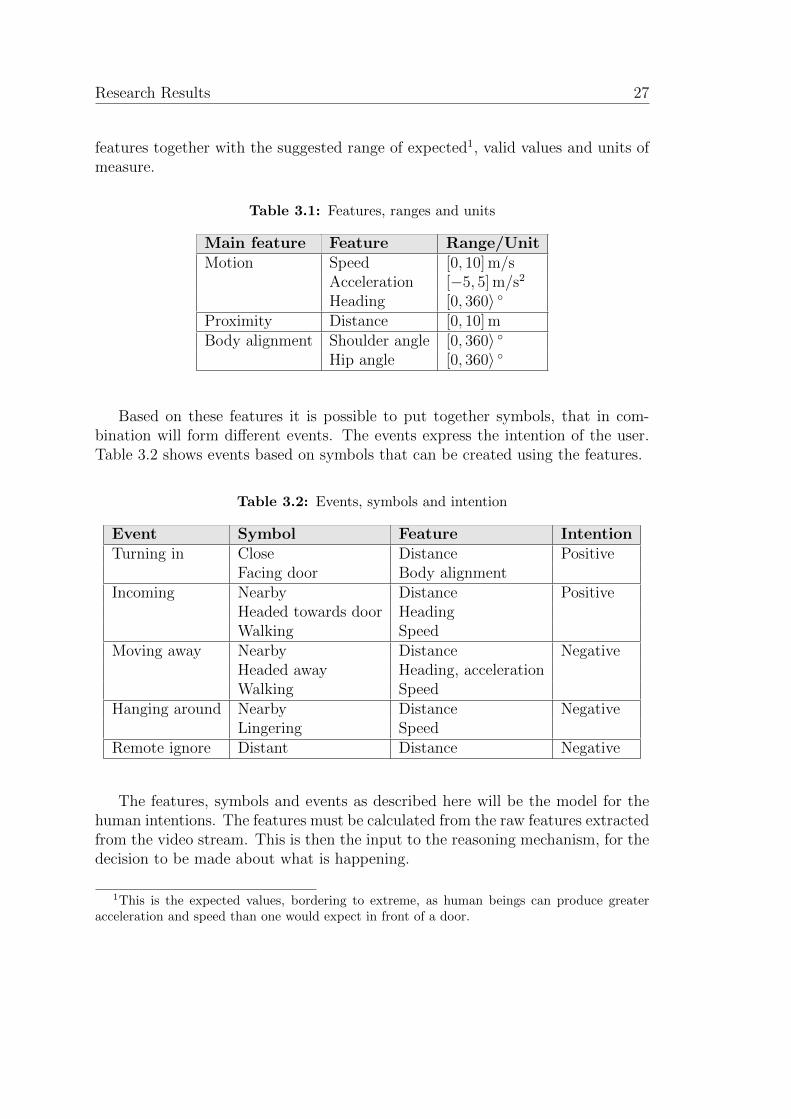
Research Results 27
features together with the suggested range of expected1, valid values and units ofmeasure.
Table 3.1: Features, ranges and units
Main feature Feature Range/UnitMotion Speed [0, 10] m/s
Acceleration [−5, 5] m/s2
Heading [0, 360〉 Proximity Distance [0, 10] mBody alignment Shoulder angle [0, 360〉
Hip angle [0, 360〉
Based on these features it is possible to put together symbols, that in com-bination will form different events. The events express the intention of the user.Table 3.2 shows events based on symbols that can be created using the features.
Table 3.2: Events, symbols and intention
Event Symbol Feature IntentionTurning in Close Distance Positive
Facing door Body alignmentIncoming Nearby Distance Positive
Headed towards door HeadingWalking Speed
Moving away Nearby Distance NegativeHeaded away Heading, accelerationWalking Speed
Hanging around Nearby Distance NegativeLingering Speed
Remote ignore Distant Distance Negative
The features, symbols and events as described here will be the model for thehuman intentions. The features must be calculated from the raw features extractedfrom the video stream. This is then the input to the reasoning mechanism, for thedecision to be made about what is happening.
1This is the expected values, bordering to extreme, as human beings can produce greateracceleration and speed than one would expect in front of a door.
ii
“report” — 2011/6/20 — 15:25 — page 28 — #42 ii
ii
ii
28 Capturing the intention
3.2 Capturing the intention
With the model of features for human behavior in mind, the capturing process isgiven a direction. The features that need to be extracted are defined. In Section 2.2different approaches were discussed, and a set of tools were presented. A capturingmechanism must obey the following requirements:
• Real-time handling
• Body recognition
• Body tracking
• Depth mapping
A sliding door operates in a real environment. Since the system must capture,analyze and respond to a user’s behavior, it is very important with real-timehandling. Time-consuming tasks could create unacceptable delays, resulting ina non-functional door. It is therefore important to know how the different toolsperform.
3.2.1 Evaluation of computer vision tools
All testing was done on a computer with Intel Core 2 Duo 3.0 GHz and 3.7 GiB ofRAM. The algorithms were tested using a video clip consisting of 114 consecutiveframes, each frame treated separately. Based on the features as defined in Table 3.1(page 27), I need frame rates of at least 10-15 frames per second (fps).
Traditional segmentation techniques
The traditionally used computer vision techniques build the foundation for manytasks. Although methods like Sobel and Canny for edge detection function well,some additional steps are required for detecting humans. The Otsu algorithm forseparating foreground from background was tried out, as well as using image sub-traction, finding the difference between two images (one serving as a backgroundmodel) as raw input for human detection.
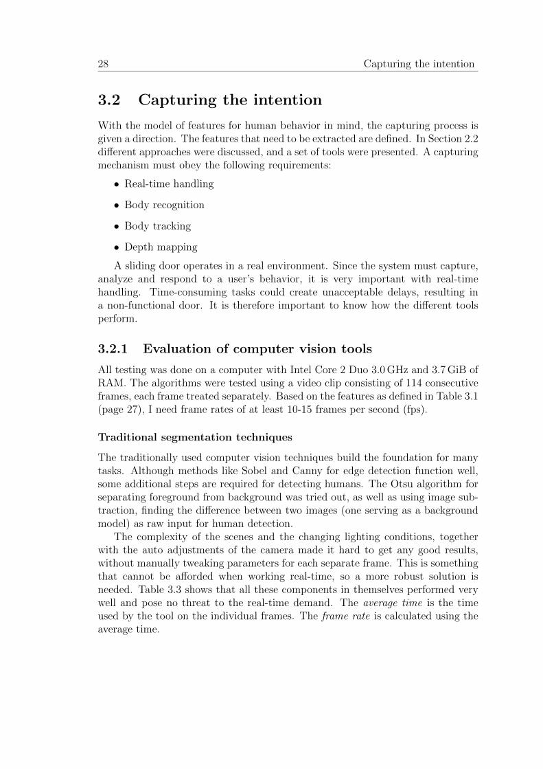
The complexity of the scenes and the changing lighting conditions, togetherwith the auto adjustments of the camera made it hard to get any good results,without manually tweaking parameters for each separate frame. This is somethingthat cannot be afforded when working real-time, so a more robust solution isneeded. Table 3.3 shows that all these components in themselves performed verywell and pose no threat to the real-time demand. The average time is the timeused by the tool on the individual frames. The frame rate is calculated using theaverage time.
ii
“report” — 2011/6/20 — 15:25 — page 29 — #43 ii
ii
ii
Research Results 29
Table 3.3: Performance of different segmentation tools
Frame size Segmentation tool Average time Frame rate480x640 Canny edge detection 8 ms 125 fps
Otsu threshold 2.1 ms 474 fpsImage subtraction 1.8 ms 558 fps
Histogram of Oriented Gradients
Object detection using the oriented gradients overcomes some of the problemswith the more traditional methods. It provides a robust mechanism for detectingobjects, even in challenging environments. OpenCV2 has got an implementationof this detector following the original description by Dalal and Triggs (2005). Theoriginal implementation suffers from low performance and might not deliver theperformance needed for a real-time system, but improvements can be made. Thetests were run using this implementation together with the supplied defaultPeo-pleDetector, an already trained people detector.
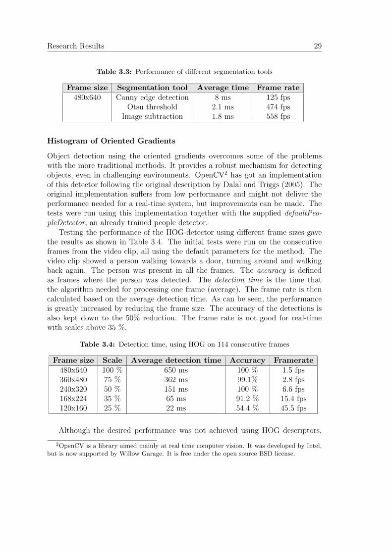
Testing the performance of the HOG-detector using different frame sizes gavethe results as shown in Table 3.4. The initial tests were run on the consecutiveframes from the video clip, all using the default parameters for the method. Thevideo clip showed a person walking towards a door, turning around and walkingback again. The person was present in all the frames. The accuracy is definedas frames where the person was detected. The detection time is the time thatthe algorithm needed for processing one frame (average). The frame rate is thencalculated based on the average detection time. As can be seen, the performanceis greatly increased by reducing the frame size. The accuracy of the detections isalso kept down to the 50% reduction. The frame rate is not good for real-timewith scales above 35 %.
Table 3.4: Detection time, using HOG on 114 consecutive frames
Frame size Scale Average detection time Accuracy Framerate480x640 100 % 650 ms 100 % 1.5 fps360x480 75 % 362 ms 99.1% 2.8 fps240x320 50 % 151 ms 100 % 6.6 fps168x224 35 % 65 ms 91.2 % 15.4 fps120x160 25 % 22 ms 54.4 % 45.5 fps
Although the desired performance was not achieved using HOG descriptors,
2OpenCV is a library aimed mainly at real time computer vision. It was developed by Intel,but is now supported by Willow Garage. It is free under the open source BSD license.
ii
“report” — 2011/6/20 — 15:25 — page 30 — #44 ii
ii
ii
30 Capturing the intention
work can be done to improve the implementation. Research has been done indelivering real-time performance with HOG (Zhu et al., 2006; Jia and Zhang, 2007).Further improvements are suggested where accuracy is improved and detectiontime reduced (Wang and Zhang, 2008). Using the computer’s GPU for some ofthe workload may also increase the performance radically (Lillywhite et al., 2009;Bilgic et al., 2010; Sugano et al., 2010).
Attempts have been made in combining stereo vision and HOG descriptors,achieving better accuracy as well as real-time performance (Toya et al., 2008).This solution seems promising and might have had advantages for my projectsince information provided by stereo vision is needed anyway.
Recognizing human shapes in the images is just one component of the completesystem. Getting the HOG-algoritms up to speed would only solve parts of theproblem. With limited time and no good implementation of the algorithms athand, it was better to look for alternatives.
3.2.2 Kinect and OpenNI
Following the development and the usage of the Kinect sensor device within theOpen source community, new possibilities opened. This device is created for track-ing humans, and can take on the depth calculations, giving more resources to otherimportant tasks.
Kinect
The Kinect is a controller device produced for Microsoft’s gaming console Xbox360. It allows for motion tracking and gesture recognition through the built-inRGB-camera and depth sensor. Although the device is designed for use with aconsole, it is also possible to connect it to a computer. This however, requires aseparate driver suitable for the Kinect. The device produces raw data in the formsof RGB data (color images) and depth data (depth map with distances in millime-ters). The raw data must then be processed using software specially designed forthe purpose. The device delivers its data well within real-time specifications, andcan support an application that has real-time demands.
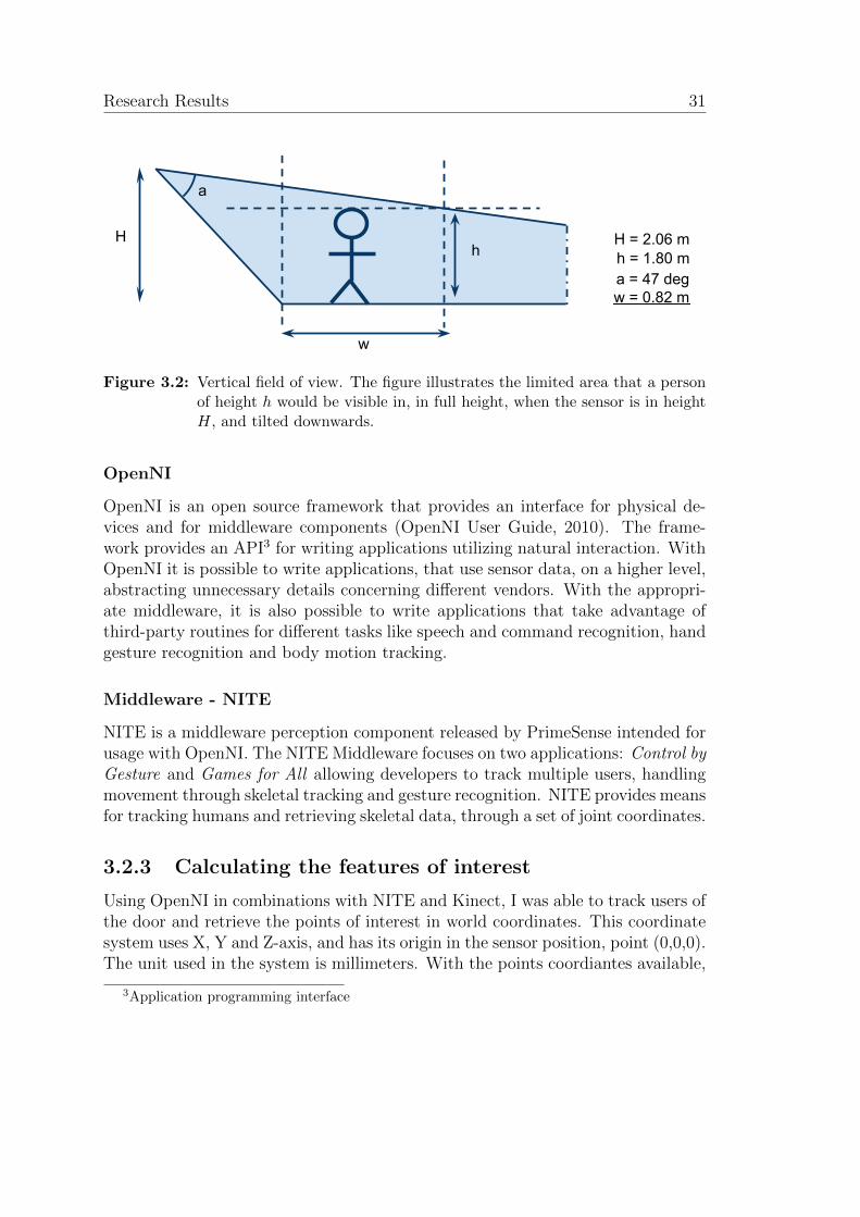
After experimenting with the Kinect, I found out that the vertical field of viewis about 47. When mounting the sensor above the door, one would have to tiltit downwards in order to cover the area close to the door. This will limit thedepth of the field. However, this would also be a problem on most of the ordinarycameras available, the ones I tested included. Figure 3.2 illustrates limitations inthe vertical field of view.
ii
“report” — 2011/6/20 — 15:25 — page 31 — #45 ii
ii
ii
Research Results 31
H = 2.06 mh = 1.80 m
Hh
w
a
a = 47 degw = 0.82 m
Figure 3.2: Vertical field of view. The figure illustrates the limited area that a personof height h would be visible in, in full height, when the sensor is in heightH, and tilted downwards.
OpenNI
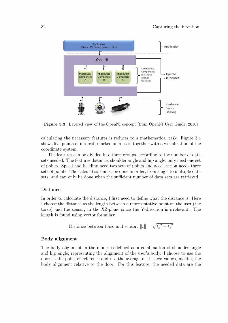
OpenNI is an open source framework that provides an interface for physical de-vices and for middleware components (OpenNI User Guide, 2010). The frame-work provides an API3 for writing applications utilizing natural interaction. WithOpenNI it is possible to write applications, that use sensor data, on a higher level,abstracting unnecessary details concerning different vendors. With the appropri-ate middleware, it is also possible to write applications that take advantage ofthird-party routines for different tasks like speech and command recognition, handgesture recognition and body motion tracking.
Middleware - NITE
NITE is a middleware perception component released by PrimeSense intended forusage with OpenNI. The NITE Middleware focuses on two applications: Control byGesture and Games for All allowing developers to track multiple users, handlingmovement through skeletal tracking and gesture recognition. NITE provides meansfor tracking humans and retrieving skeletal data, through a set of joint coordinates.
3.2.3 Calculating the features of interest
Using OpenNI in combinations with NITE and Kinect, I was able to track users ofthe door and retrieve the points of interest in world coordinates. This coordinatesystem uses X, Y and Z-axis, and has its origin in the sensor position, point (0,0,0).The unit used in the system is millimeters. With the points coordiantes available,
3Application programming interface
ii
“report” — 2011/6/20 — 15:25 — page 32 — #46 ii
ii
ii
32 Capturing the intention
Figure 3.3: Layered view of the OpenNI concept (from OpenNI User Guide, 2010)
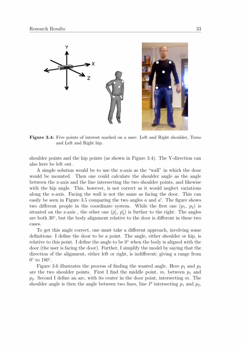
calculating the necessary features is reduces to a mathematical task. Figure 3.4shows five points of interest, marked on a user, together with a visualization of thecoordinate system.
The features can be divided into three groups, according to the number of datasets needed. The features distance, shoulder angle and hip angle, only need one setof points. Speed and heading need two sets of points and acceleration needs threesets of points. The calculations must be done in order, from single to multiple datasets, and can only be done when the sufficient number of data sets are retrieved.
Distance
In order to calculate the distance, I first need to define what the distance is. HereI choose the distance as the length between a representative point on the user (thetorso) and the sensor, in the XZ-plane since the Y-direction is irrelevant. Thelength is found using vector formulas:
Distance between torso and sensor: ‖~t‖ =√tx
2 + tz2
Body alignment
The body alignment in the model is defined as a combination of shoulder angleand hip angle, representing the alignment of the user’s body. I choose to use thedoor as the point of reference and use the average of the two values, making thebody alignment relative to the door. For this feature, the needed data are the
ii
“report” — 2011/6/20 — 15:25 — page 33 — #47 ii
ii
ii
Research Results 33
Figure 3.4: Five points of interest marked on a user: Left and Right shoulder, Torsoand Left and Right hip.
shoulder points and the hip points (as shown in Figure 3.4). The Y-direction canalso here be left out.
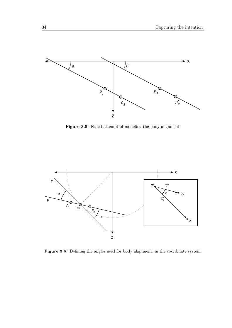
A simple solution would be to use the x-axis as the “wall” in which the doorwould be mounted. Then one could calculate the shoulder angle as the anglebetween the x-axis and the line intersecting the two shoulder points, and likewisewith the hip angle. This, however, is not correct as it would neglect variationsalong the x-axis. Facing the wall is not the same as facing the door. This caneasily be seen in Figure 3.5 comparing the two angles a and a′. The figure showstwo different people in the coordinate system. While the first one (p1, p2) issituated on the z-axis , the other one (p′1, p
′2) is further to the right. The angles
are both 30, but the body alignment relative to the door is different in these twocases.
To get this angle correct, one must take a different approach, involving somedefinitions: I define the door to be a point. The angle, either shoulder or hip, isrelative to this point. I define the angle to be 0 when the body is aligned with thedoor (the user is facing the door). Further, I simplify the model by saying that thedirection of the alignment, either left or right, is indifferent; giving a range from0 to 180.
Figure 3.6 illustrates the process of finding the wanted angle. Here p1 and p2are the two shoulder points. First I find the middle point, m, between p1 andp2. Second I define an arc, with its center in the door point, intersecting m. Theshoulder angle is then the angle between two lines, line P intersecting p1 and p2,
ii
“report” — 2011/6/20 — 15:25 — page 34 — #48 ii
ii
ii
34 Capturing the intention
p1
p2
X
Z
a
p'1
p'2
a'
Figure 3.5: Failed attempt of modeling the body alignment.
p
v1
1pm2
X
Z
a
a p
m
z
a
v22
T
P
Figure 3.6: Defining the angles used for body alignment, in the coordinate system.
ii
“report” — 2011/6/20 — 15:25 — page 35 — #49 ii
ii
ii
Research Results 35
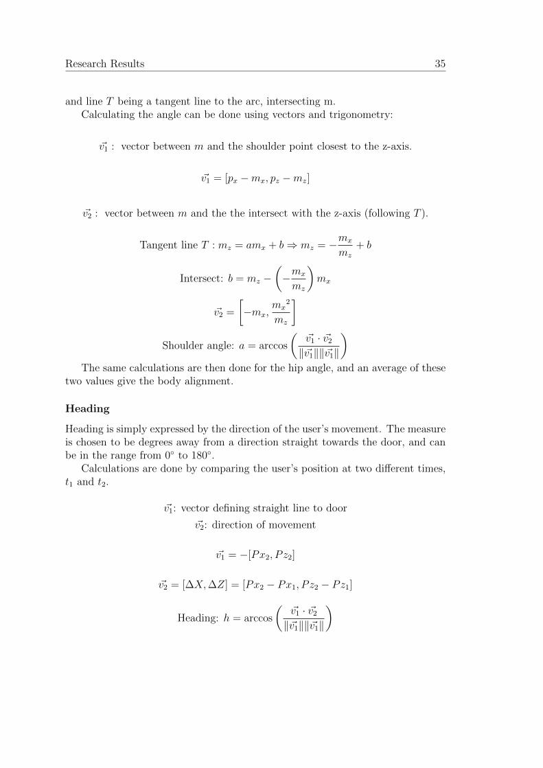
and line T being a tangent line to the arc, intersecting m.Calculating the angle can be done using vectors and trigonometry:
~v1 : vector between m and the shoulder point closest to the z-axis.
~v1 = [px −mx, pz −mz]
~v2 : vector between m and the the intersect with the z-axis (following T ).
Tangent line T : mz = amx + b⇒ mz = −mx
mz
+ b
Intersect: b = mz −(−mx
mz
)mx
~v2 =
[−mx,
mx2
mz
]Shoulder angle: a = arccos
(~v1 · ~v2‖~v1‖‖~v1‖
)The same calculations are then done for the hip angle, and an average of these
two values give the body alignment.
Heading
Heading is simply expressed by the direction of the user’s movement. The measureis chosen to be degrees away from a direction straight towards the door, and canbe in the range from 0 to 180.
Calculations are done by comparing the user’s position at two different times,t1 and t2.
~v1: vector defining straight line to door
~v2: direction of movement
~v1 = −[Px2, P z2]
~v2 = [∆X,∆Z] = [Px2 − Px1, P z2 − Pz1]
Heading: h = arccos
(~v1 · ~v2‖~v1‖‖~v1‖
)

ii
“report” — 2011/6/20 — 15:25 — page 36 — #50 ii
ii
ii
36 To open or not to open
Speed
The calculation of speed uses the same data as heading, as well as the time differ-ence between t1 and t2. The speed as defined here leaves out direction.
Speed: v =s
t=
√(∆X)2 + (∆Z)2
t2 − t1=
√(Px2 − Px1)2 + (Pz2 − Pz1)2
t2 − t1
Acceleration
Calculating acceleration requires more data sets than the other calculations. Ac-celeration can be calculated by using the velocity at two different time points andthe elapsed time between them.
v0: initial velocity, v: final velocity, t: elapsed time
Acceleration: a =v − v0t
3.3 To open or not to open
The research done in the preparation work pointed out rule-based reasoning as awell suited mechanism for infering intentions (see Section 2.3.4, page 21). Themodel of human behavior and intention defined symbols and events; they can beseen as input to the reasoning process.
The user tracking process provides the points of interest that are used for thecalculation of features. All points collected from one sensor update, produce thefeatures belonging to this set of points. The features can then be grouped intofeature sets, belonging to one specific user with one timestamp.
The feature sets are the input for the reasoning mechanism. Providing a stackof feature sets for each user, may strengthen the reasoning process, by allowingthe reasoning to be based on events that form over time. Figure 3.7 shows howthe feature sets are related to users.
The system has to be able to tell if a user wants to go through the door at anytime. Rules that analyze the feature sets can do this.
3.3.1 Defining rules
Defining rules for reasoning is really a process of instantiating and grouping thesymbols described in Section 3.1.4. The values as suggested in Table 3.5 are aproduct of intuitive measures together with some trial and error and limitationsconcerning the sensor equipment and setup.

ii
“report” — 2011/6/20 — 15:25 — page 37 — #51 ii
ii
ii
Research Results 37
User1 User2
FeatureSet1FeatureSet1
FeatureSet1FeatureSet1
FeatureSet
FeatureSet1FeatureSet1
FeatureSet1FeatureSet1
FeatureSet
FeatureSet 1, ..., n FeatureSet 1, ..., n
Figure 3.7: Each user being tracked, stores a stack of feature sets.
Table 3.5: Instantiating the symbols
Feature Symbol ValueDistance Close d ∈ [0, 1.2] m
Nearby d ∈ 〈1.2, 1.8] mDistant d ∈ 〈1.8,→〉m
Speed Walking v ∈ 〈0.8, 8] m/sLingering v ∈ [0, 0.8] m/s
Body alignment Facing door ba ∈ [0, 4]
Heading Headed towards door h ∈ [0, 4]
Headed away h 6∈ [0, 4]
ii
“report” — 2011/6/20 — 15:25 — page 38 — #52 ii
ii
ii
38 To open or not to open
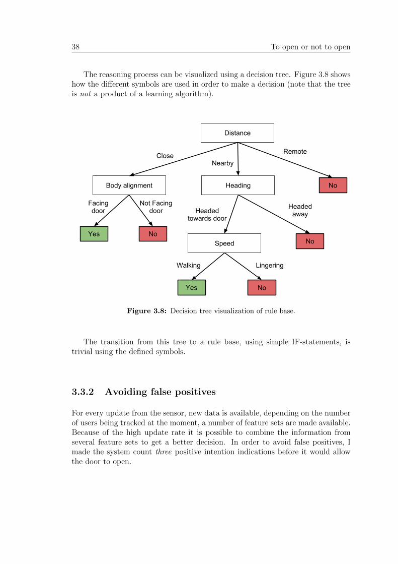
The reasoning process can be visualized using a decision tree. Figure 3.8 showshow the different symbols are used in order to make a decision (note that the treeis not a product of a learning algorithm).
Distance
Remote
NoHeading
Nearby
Yes
Headed awayHeaded
towards door
Speed
LingeringWalking
No
Yes No
Body alignment
No
Close
Facing door
Not Facing door
Figure 3.8: Decision tree visualization of rule base.
The transition from this tree to a rule base, using simple IF-statements, istrivial using the defined symbols.
3.3.2 Avoiding false positives
For every update from the sensor, new data is available, depending on the numberof users being tracked at the moment, a number of feature sets are made available.Because of the high update rate it is possible to combine the information fromseveral feature sets to get a better decision. In order to avoid false positives, Imade the system count three positive intention indications before it would allowthe door to open.
ii
“report” — 2011/6/20 — 15:25 — page 39 — #53 ii
ii
ii
Research Results 39
3.4 An automated sliding door
The most central components in the project are the sensors and the sensor readingstogether with the interpretations of these. All the main tasks are solved usingthese components. The sensors capture the movements of the users, and thecomputer analyzes the sensor readings, inferring an intention and finally decidesthe appropriate action. Although this is in its own a complete system, it is notenough. In order to evaluate the performance of the system altogether, some kindof feedback is necessary. Strictly speaking, this could have been limited to anybinary output, symbolizing a door opening. The feedback could easily have beena LED or a light bulb, lighting up whenever the system chose that open was theappropriate action. However, this is not a very good idea. The system needs toanalyze the behavior of people interacting with a door. A simulated door is harderto interact with. Walking through a simulated door is unnatural and might resultin abnormal behavior. The need for a real door is therefore present.
Figure 3.9: Abnormal behavior
An automated sliding door is a common device, and something that mostpeople are accustomed to. Having an actual working sliding door will give themost desirable conditions and accurate results.
A viable solution would have been to equip an existing door with additionalsensors. It would then be possible to evaluate the performance by comparing thesystem outputs (decisions made) with the user’s behavior and the actual dooroutputs (door opening or not). This would also provide a comparison betweenmy system and existing systems. This would however complicate the process, inseveral areas. First, a real door in a real environment, although more realistic,

ii
“report” — 2011/6/20 — 15:25 — page 40 — #54 ii
ii
ii
40 An automated sliding door
is harder to use both for development and testing. This is mostly because of theenvironmental factors that are out of my control, like the amount of people usingthe door and the lighting and weather conditions. Second, the feedback would beindirect, as the door’s actions will not always correspond to the inferred intention.My system’s output must then be checked in other ways. In other words, thecommunication that is going on is actually between the user and the existingsystem, rather than the user and my system. Third, using an actual door raisesprivacy issues, demanding alternative routes, as described in Section 3.4.2.
Having my own door that can be controlled directly, would be the best solu-tion. Ready-made, motorized doors are very expensive and buying one was not anoption. This left me with the option of building a door myself.
3.4.1 Building a door (the do-it-yourself way)
A sliding door can be very simple; take a door and put wheels on it. This isbasically how the “household” type of sliding doors are built. One might thinkthat these doors can be found everywhere. As it turns out, sliding doors are notso common, and can only be bought as complete sets. These type of doors arevery hard to customize because of the compactness needed for built-in doors. Amotor and a mechanism for pulling the doors would simply not fit in the sets. Asa result of this, I needed to build the door from scratch.
Here are some of the choices for the specifications:
• Double doors – Wider access and lower speed needed in order to open.
• Wood as building material – Cost efficient and easy to work with.
• Belt and cog wheels – Reliable and easy drive system.
The proposed solution consists of different parts:
• Door frame – A self supported frame that can hold the doors, without theneed of a wall.
• Doors – Double doors, with wheels for usage with rails in the door frame.
• Drive system – Belt and cogwheels mounted on top of the door frame, pulledby an electrical motor.
• Door controller system – Electronic component, computer controlled andable to run the motor, in both directions, at correct speed.
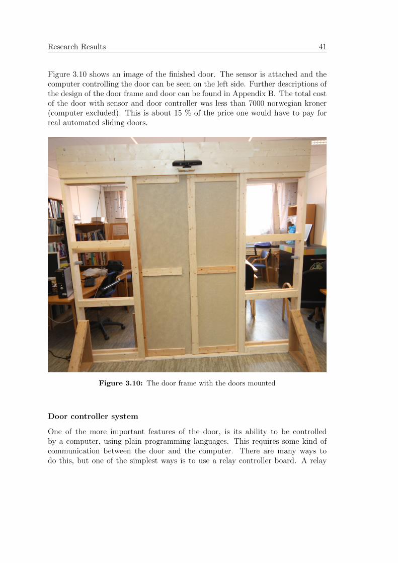
ii
“report” — 2011/6/20 — 15:25 — page 41 — #55 ii
ii
ii
Research Results 41
Figure 3.10 shows an image of the finished door. The sensor is attached and thecomputer controlling the door can be seen on the left side. Further descriptions ofthe design of the door frame and door can be found in Appendix B. The total costof the door with sensor and door controller was less than 7000 norwegian kroner(computer excluded). This is about 15 % of the price one would have to pay forreal automated sliding doors.
Figure 3.10: The door frame with the doors mounted
Door controller system
One of the more important features of the door, is its ability to be controlledby a computer, using plain programming languages. This requires some kind ofcommunication between the door and the computer. There are many ways todo this, but one of the simplest ways is to use a relay controller board. A relay
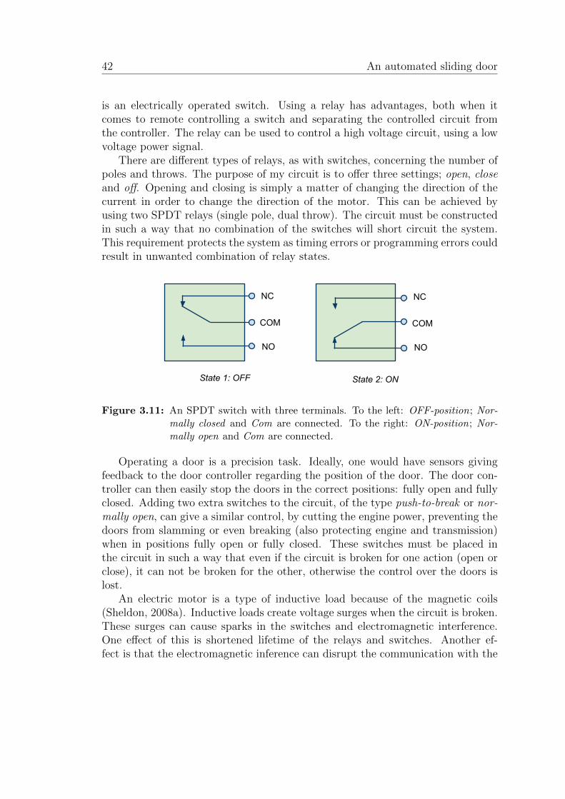
ii
“report” — 2011/6/20 — 15:25 — page 42 — #56 ii
ii
ii
42 An automated sliding door
is an electrically operated switch. Using a relay has advantages, both when itcomes to remote controlling a switch and separating the controlled circuit fromthe controller. The relay can be used to control a high voltage circuit, using a lowvoltage power signal.
There are different types of relays, as with switches, concerning the number ofpoles and throws. The purpose of my circuit is to offer three settings; open, closeand off. Opening and closing is simply a matter of changing the direction of thecurrent in order to change the direction of the motor. This can be achieved byusing two SPDT relays (single pole, dual throw). The circuit must be constructedin such a way that no combination of the switches will short circuit the system.This requirement protects the system as timing errors or programming errors couldresult in unwanted combination of relay states.
COM
NO
NC
State 1: OFF
COM
NO
NC
State 2: ON
Figure 3.11: An SPDT switch with three terminals. To the left: OFF-position; Nor-mally closed and Com are connected. To the right: ON-position; Nor-mally open and Com are connected.
Operating a door is a precision task. Ideally, one would have sensors givingfeedback to the door controller regarding the position of the door. The door con-troller can then easily stop the doors in the correct positions: fully open and fullyclosed. Adding two extra switches to the circuit, of the type push-to-break or nor-mally open, can give a similar control, by cutting the engine power, preventing thedoors from slamming or even breaking (also protecting engine and transmission)when in positions fully open or fully closed. These switches must be placed inthe circuit in such a way that even if the circuit is broken for one action (open orclose), it can not be broken for the other, otherwise the control over the doors islost.
An electric motor is a type of inductive load because of the magnetic coils(Sheldon, 2008a). Inductive loads create voltage surges when the circuit is broken.These surges can cause sparks in the switches and electromagnetic interference.One effect of this is shortened lifetime of the relays and switches. Another ef-fect is that the electromagnetic inference can disrupt the communication with the
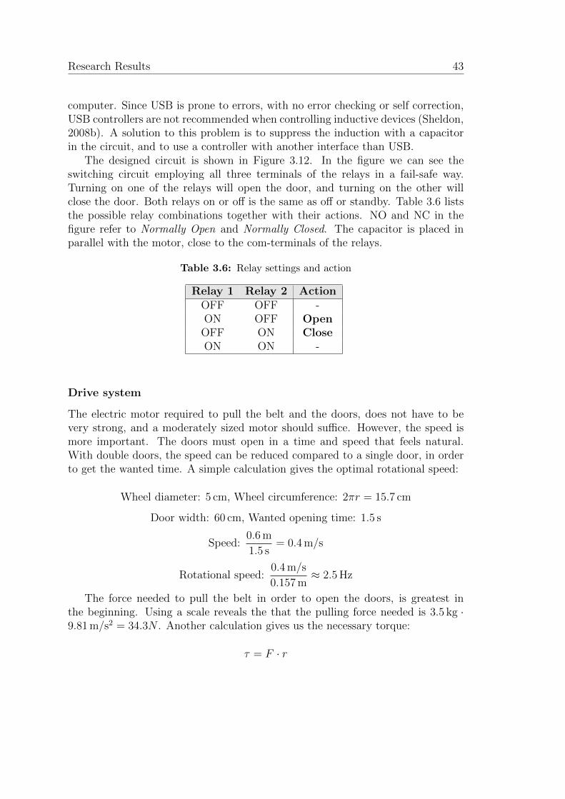
ii
“report” — 2011/6/20 — 15:25 — page 43 — #57 ii
ii
ii
Research Results 43
computer. Since USB is prone to errors, with no error checking or self correction,USB controllers are not recommended when controlling inductive devices (Sheldon,2008b). A solution to this problem is to suppress the induction with a capacitorin the circuit, and to use a controller with another interface than USB.
The designed circuit is shown in Figure 3.12. In the figure we can see theswitching circuit employing all three terminals of the relays in a fail-safe way.Turning on one of the relays will open the door, and turning on the other willclose the door. Both relays on or off is the same as off or standby. Table 3.6 liststhe possible relay combinations together with their actions. NO and NC in thefigure refer to Normally Open and Normally Closed. The capacitor is placed inparallel with the motor, close to the com-terminals of the relays.
Table 3.6: Relay settings and action
Relay 1 Relay 2 ActionOFF OFF -ON OFF Open
OFF ON CloseON ON -
Drive system
The electric motor required to pull the belt and the doors, does not have to bevery strong, and a moderately sized motor should suffice. However, the speed ismore important. The doors must open in a time and speed that feels natural.With double doors, the speed can be reduced compared to a single door, in orderto get the wanted time. A simple calculation gives the optimal rotational speed:
Wheel diameter: 5 cm, Wheel circumference: 2πr = 15.7 cm
Door width: 60 cm, Wanted opening time: 1.5 s
Speed:0.6 m
1.5 s= 0.4 m/s
Rotational speed:0.4 m/s
0.157 m≈ 2.5 Hz
The force needed to pull the belt in order to open the doors, is greatest inthe beginning. Using a scale reveals the that the pulling force needed is 3.5 kg ·9.81 m/s2 = 34.3N . Another calculation gives us the necessary torque:
τ = F · r
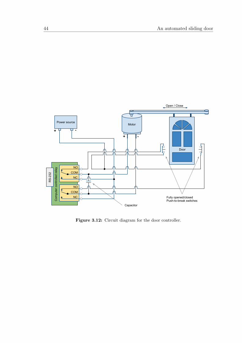
ii
“report” — 2011/6/20 — 15:25 — page 44 — #58 ii
ii
ii
44 An automated sliding door
Motor
RS-
232
Com
pute
r con
trolle
d re
lay
-
Power source
++ -
NC
NO
COM
NC
NO
COM
Open / Close
Door
Fully opened/closedPush-to-break switches
Capacitor
Figure 3.12: Circuit diagram for the door controller.

ii
“report” — 2011/6/20 — 15:25 — page 45 — #59 ii
ii
ii
Research Results 45
τ = 34.3 N · 0.025 m
τ = 0.86 N m
Both speed and torque of these sizes can easily be supplied by a simple electricmotor like the ones in a battery powered drill. The finished drive system can beseen in Figure 3.13.
Figure 3.13: Picture showing the drive system. The drill is on the left; the beltstretches along the door and the wheels are in each end.
Testing and redesigning
The drill that I got for the setup provided faster rotational speed than necessary,so the circuit was expanded with a resistor. With a battery that gave 12 V, theideal door speed was obtained by inserting a resistor of 0.5 Ω. Because of thehigh current (about 8 A) and the generated heat, it was necessary to use multipleresistors of higher resistance in parallel instead of one smaller. Equations (3.1)and (3.2) show that using three resistors of 1.5 Ω in parallel give the wanted totalresistance. To protect the electronics and the circuit, I also installed a fuse ratedto 10 A.

ii
“report” — 2011/6/20 — 15:25 — page 46 — #60 ii
ii
ii
46 An automated sliding door
Resistors in parallel:1
Rtot
=1
R1
+1
R2
+1
R3
(3.1)
1
0.5 Ω=
1
r+
1
r+
1
r⇒ r = 1.5 Ω (3.2)
When using the door for a longer period of time, I found that the battery didnot supply a current that was stable enough for controlling the door; the voltagedropped and the door did not fully open and close. The solution to this problemwas to replace the battery with a wall connected power supply. The power neededfor my circuit is higher than the ones provided by simple power supplies wherea transformer is plugged into the wall socket. A better alternative is to use anATX computer power supply unit (PSU). This unit can provide a stable voltagesupporting higher currents. The power needed can easily be calculated:
P = U · I12 V · 8 A = 96 W
≈ 100 W
A suited power supply was rated to 300 W with max current of 16 A on a 12 Vchannel. The design guide for ATX power supplies (Intel, 2007), explained thelayouts for the different connectors and proved helpful when putting the PSU touse.
Since the PSU is not controlled by a computer, no signal is sent to power upthe unit. This is usually controlled with the PS ON#-pin (pin 16) on the mainpower connector. The PS ON# is an active-low, TTL-compatible4 signal. WhenPS ON# is pulled to low, the power supply turns on the output rails. WhenPS ON# is pulled to high or open-circuited the output rails deliver no current(Intel, 2007). Connecting PS ON# to a COM (ground) pulled the signal to low,providing a constant supply of power. The layout of the connectors together withthe used pins can be seen in Figure 3.14 and Table 3.7.
Any one of the power connectors with a +12 V line could have been usedto provide the power for the controller circuit. I chose to use one of the manyperipheral power connectors. The connector layout and the usage is shown inFigure 3.14 and Table 3.8. The finished door controller can be seen in Figure 3.15.
4TTL – Transistor-transistor logic, digital signaling that uses voltage levels representing log-ical states.

ii
“report” — 2011/6/20 — 15:25 — page 47 — #61 ii
ii
ii
Research Results 47
1 12
13 24
Main Power Connector Peripheral Power Connector
1 4
Figure 3.14: Connector layout for an ATX power supply unit
Table 3.7: Pin layout for ATX Main Power Connector. Connecting pin 7 and 16 turnedthe power supply on.
Pin Signal Color Pin Signal Color1 +3.3VDC Orange 13 +3.3VDC Orange2 +3.3VDC Orange 14 -12VDC Blue3 COM Black 15 COM Black4 +5VDC Red 16 PS ON# Green5 COM Black 17 COM Black6 +5VDC Red 18 COM Black7 COM Black 19 COM Black8 PWR OK Gray 20 Reserved N/C9 +5VSB Purple 21 +5VDC Red10 +12VDC Yellow 22 +5VDC Red11 +12VDC Yellow 23 +5VDC Red12 +3.3VDC Orange 24 COM Black
Table 3.8: Pin layout for ATX Peripheral Power Connector. Pin 1 (yellow wire) and 2(black wire) were connected to the controller circuit, replacing the battery.
Pin Signal Color1 +12VDC Yellow2 COM Black3 COM Black4 +5VDC Red
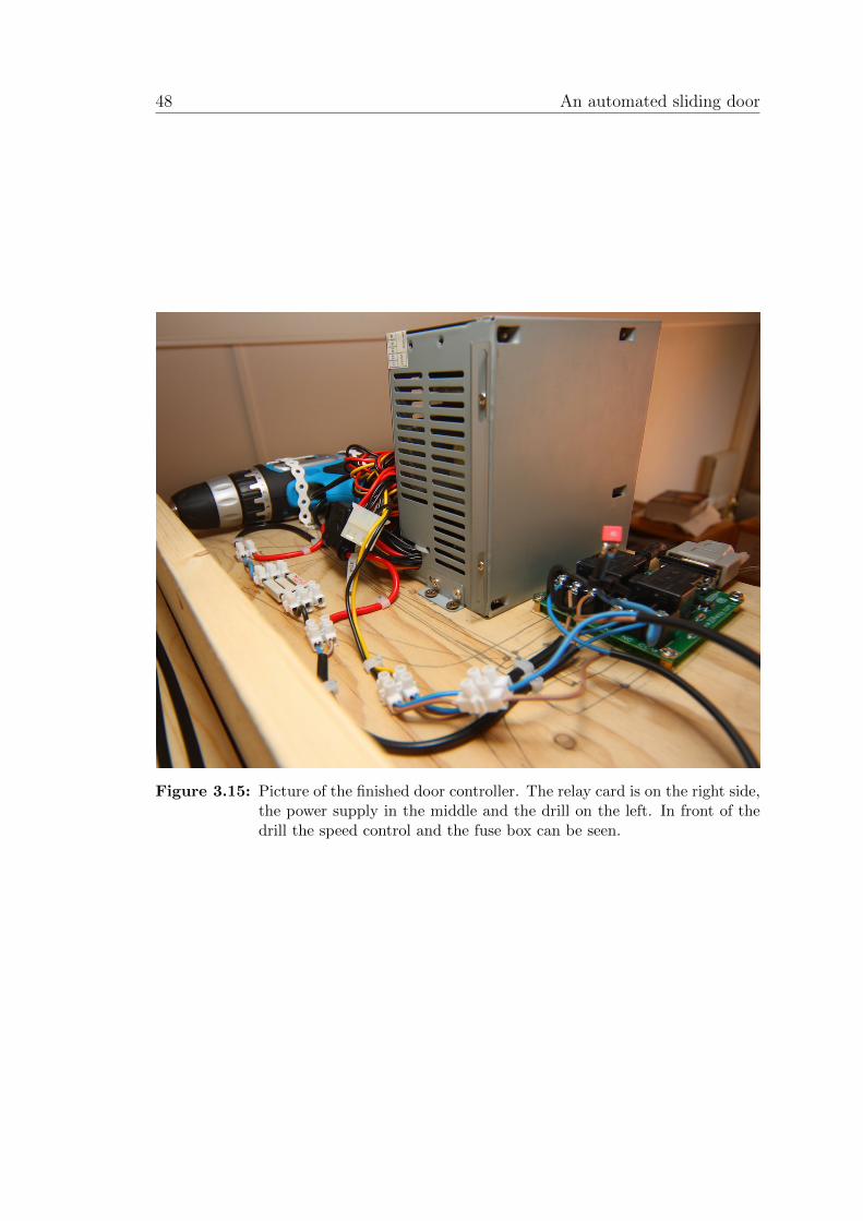
ii
“report” — 2011/6/20 — 15:25 — page 48 — #62 ii
ii
ii
48 An automated sliding door
Figure 3.15: Picture of the finished door controller. The relay card is on the right side,the power supply in the middle and the drill on the left. In front of thedrill the speed control and the fuse box can be seen.
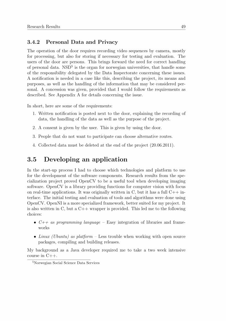
ii
“report” — 2011/6/20 — 15:25 — page 49 — #63 ii
ii
ii
Research Results 49
3.4.2 Personal Data and Privacy
The operation of the door requires recording video sequences by camera, mostlyfor processing, but also for storing if necessary for testing and evaluation. Theusers of the door are persons. This brings forward the need for correct handlingof personal data. NSD5 is the organ for norwegian universities, that handle someof the responsibility delegated by the Data Inspectorate concerning these issues.A notification is needed in a case like this, describing the project, its means andpurposes, as well as the handling of the information that may be considered per-sonal. A concession was given, provided that I would follow the requirements asdescribed. See Appendix A for details concerning the issue.
In short, here are some of the requirements:
1. Written notification is posted next to the door, explaining the recording ofdata, the handling of the data as well as the purpose of the project.
2. A consent is given by the user. This is given by using the door.
3. People that do not want to participate can choose alternative routes.
4. Collected data must be deleted at the end of the project (20.06.2011).
3.5 Developing an application
In the start-up process I had to choose which technologies and platform to usefor the development of the software components. Research results from the spe-cialization project proved OpenCV to be a useful tool when developing imagingsoftware. OpenCV is a library providing functions for computer vision with focuson real-time applications. It was originally written in C, but it has a full C++ in-terface. The initial testing and evaluation of tools and algorithms were done usingOpenCV. OpenNI is a more specialized framework, better suited for my project. Itis also written in C, but a C++ wrapper is provided. This led me to the followingchoices:
• C++ as programming language – Easy integration of libraries and frame-works
• Linux (Ubuntu) as platform – Less trouble when working with open sourcepackages, compiling and building releases.
My background as a Java developer required me to take a two week intensivecourse in C++.
5Norwegian Social Science Data Services
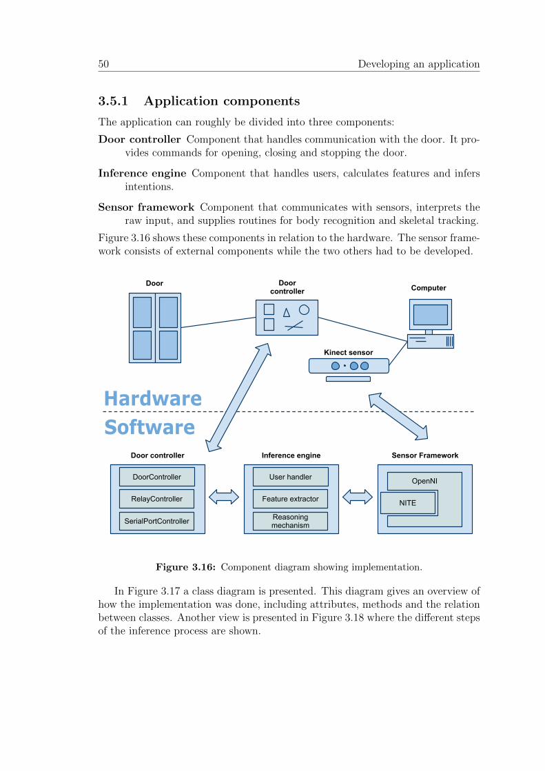
ii
“report” — 2011/6/20 — 15:25 — page 50 — #64 ii
ii
ii
50 Developing an application
3.5.1 Application components
The application can roughly be divided into three components:
Door controller Component that handles communication with the door. It pro-vides commands for opening, closing and stopping the door.
Inference engine Component that handles users, calculates features and infersintentions.
Sensor framework Component that communicates with sensors, interprets theraw input, and supplies routines for body recognition and skeletal tracking.
Figure 3.16 shows these components in relation to the hardware. The sensor frame-work consists of external components while the two others had to be developed.
Door ComputerDoor controller
Kinect sensor
Inference engine
User handler
Feature extractor
Reasoning mechanism
Sensor Framework
NITE
OpenNI
Door controller
DoorController
RelayController
SerialPortController
Figure 3.16: Component diagram showing implementation.
In Figure 3.17 a class diagram is presented. This diagram gives an overview ofhow the implementation was done, including attributes, methods and the relationbetween classes. Another view is presented in Figure 3.18 where the different stepsof the inference process are shown.
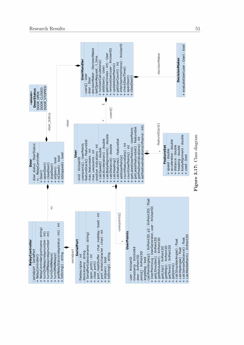
ii
“report” — 2011/6/20 — 15:25 — page 51 — #65 ii
ii
ii
Research Results 51«enum»
DoorStatus
DO
OR
_O
PE
ND
OO
R_C
LO
SE
DD
OO
R_S
TO
PPE
D
-rc
-userp
oin
ts[]
1
-door_
sta
tus
-seri
alp
ort
-door
Door
- d
oor_
sta
tus :
DoorS
tatu
s-
rc :
Rela
yC
on
troller
+ D
oor(
)+
op
en
Door(
)+
clo
seD
oor(
)+
sto
pD
oor(
)+
isO
pen
() :
bool
+ isC
losed
() :
bool
+ isS
top
ped
() :
bool
UserHandler
- u
sers
[] :
User
- d
oor
: D
oor
- d
ecis
ion
Maker
: D
ecis
ion
Maker
- la
stO
pen
Req
uest
: t_
tim
e+
ru
nU
serC
alc
ula
tion
s()
+ a
dd
User(
u :
User)
+ g
etU
ser(
ind
ex :
in
t) :
User
+ r
em
oveU
ser(
user
: X
nU
serI
D)
+ u
pd
ate
UserP
oin
ts()
+ g
etU
serC
ou
nt(
) :
int
+ in
ferU
serI
nte
nti
on
s()
: X
nU
serI
D+
ch
eckD
oorT
ime()
+ o
pen
Door(
)+
clo
seD
oor(
)
1*
-users
[]
-decis
ion
Maker
User
- xn
id :
Xn
UserI
D-
userp
oin
ts[]
: U
serP
oin
ts-
featu
reS
tack[]
: F
eatu
reS
et
- m
ax_fe
atu
resets
: in
t-
max_u
serp
oin
ts :
in
t-
posit
ive_in
dic
ati
on
s :
in
t+
calc
Sp
eed
() :
dou
ble
+ c
alc
Accele
rati
on
() :
dou
ble
+ c
alc
Bod
yA
lig
nm
en
t()
: d
ou
ble
+ c
alc
Dis
tan
ce()
: d
ou
ble
+ c
alc
Head
ing
()+
calc
Featu
res()
: F
eatu
reS
et
+ a
dd
UserP
oin
ts()
+ c
ou
ntF
eatu
reS
ets
() :
in
t+
cou
ntU
serP
oin
ts()
: in
t+
getL
ate
stU
serP
oin
ts()
: U
serP
oin
ts+
getL
ate
stF
eatu
reS
et(
) :
Featu
reS
et
+ g
etP
osit
iveIn
dic
ati
on
s()
: in
t+
setP
osit
iveIn
dic
ati
on
s(n
PosIn
d :
in
t)
SerialPort
- fi
led
escri
pto
r :
int
- d
evic
en
am
e :
str
ing
+ S
eri
alP
ort
(devic
en
am
e :
str
ing
)+
op
en
_p
ort
() :
in
t+
clo
se_p
ort
()+
port
_re
ad
(bu
ffer
: ch
ar,
nod
ela
y :
bool)
: in
t+
port
_w
rite
(ch
ara
cte
r :
ch
ar)
: in
t+
isO
pen
() :
bool
+ t
oS
trin
g()
: s
trin
g
DecisionMaker
+ e
valu
ate
User(
user
: U
ser)
: b
ool
RelayController
- seri
alp
ort
: S
eri
alP
ort
+ R
ela
yC
on
troller(
)+
Rela
yC
on
troller(
port
nam
e :
str
ing
)+
tu
rnO
nRela
y(r
ela
yn
um
ber
: in
t)+
tu
rnO
ffRela
y(r
ela
yn
um
ber
: in
t)+
tu
rnO
nA
llRela
ys()
+ t
urn
Off
AllRela
ys()
+ g
etR
ela
yS
tatu
s(r
ela
ysta
tus :
in
t) :
in
t+
toS
trin
g()
: s
trin
g
FeatureSet
+ s
peed
: d
ou
ble
+ a
ccele
rati
on
: d
ou
ble
+ d
ista
nce :
dou
ble
+ h
ead
ing
: d
ou
ble
+ b
od
yA
lig
nm
en
t :
dou
ble
+ u
sed
: b
ool
*1
*
-featu
reS
tack[]
UserPoints
- u
ser
: X
nU
serI
D-
tim
esta
mp
: X
nU
Int6
4-
door
: X
nPoin
t3D
- jo
ints
[] :
Xn
Poin
t3D
- an
gle
Deg
: b
ool
- calc
Poin
tAn
gle
(p1
: X
nPoin
t3D
, p
2 :
Xn
Poin
t3D
) :
float
+ U
serP
oin
ts(u
g :
UserG
en
era
tor,
user
: X
nU
serI
D)
+ g
etL
Sh
ou
lder(
) :
Xn
Poin
t3D
+ g
etR
sh
ou
lder(
) :
Xn
Poin
t3D
+ g
etL
hip
() :
Xn
Poin
t3D
+ g
etR
Hip
() :
Xn
Poin
t3D
+ g
etT
ors
o()
: X
nPoin
t3D
+ g
etJ
oin
ts()
+ c
alc
Sh
ou
lderA
ng
le()
: fl
oat
+ c
alc
Hip
An
gle
() :
float
+ c
alc
Sen
sorD
ista
nce()
: fl
oat
+ c
alc
Mid
dle
Poin
t()
: X
nPoin
t3D
Figure
3.17:
Cla
ssd
iagr
am
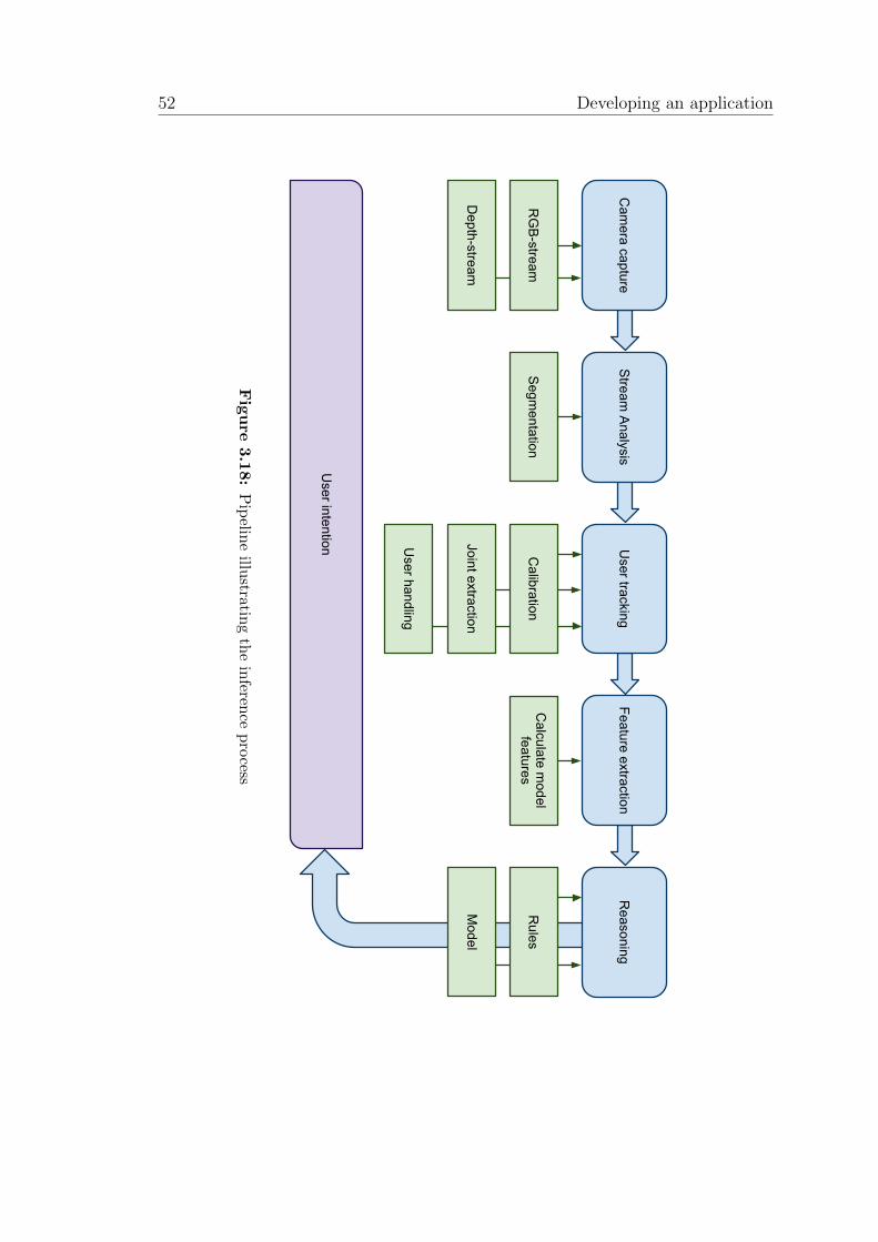
ii
“report” — 2011/6/20 — 15:25 — page 52 — #66 ii
ii
ii
52 Developing an application
Cam
era captureStream
Analysis
Depth-stream
RG
B-stream
User handling
User tracking
Segmentation
Joint extraction
Calibration
Feature extraction
Calculate m
odel features
Reasoning
Model
Rules
User intention
Figure
3.18:
Pip
eline
illustratin
gth
ein
ference
pro
cess
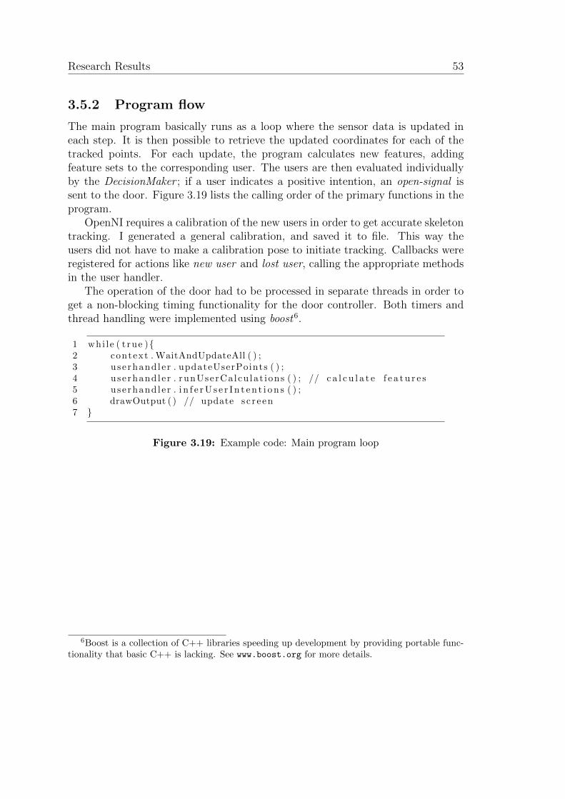
ii
“report” — 2011/6/20 — 15:25 — page 53 — #67 ii
ii
ii
Research Results 53
3.5.2 Program flow
The main program basically runs as a loop where the sensor data is updated ineach step. It is then possible to retrieve the updated coordinates for each of thetracked points. For each update, the program calculates new features, addingfeature sets to the corresponding user. The users are then evaluated individuallyby the DecisionMaker ; if a user indicates a positive intention, an open-signal issent to the door. Figure 3.19 lists the calling order of the primary functions in theprogram.
OpenNI requires a calibration of the new users in order to get accurate skeletontracking. I generated a general calibration, and saved it to file. This way theusers did not have to make a calibration pose to initiate tracking. Callbacks wereregistered for actions like new user and lost user, calling the appropriate methodsin the user handler.
The operation of the door had to be processed in separate threads in order toget a non-blocking timing functionality for the door controller. Both timers andthread handling were implemented using boost6.
1 whi l e ( t rue )2 context . WaitAndUpdateAll ( ) ;3 use rhand l e r . updateUserPoints ( ) ;4 use rhand l e r . runUserCa lcu la t ions ( ) ; // c a l c u l a t e f e a t u r e s5 use rhand le r . i n f e r U s e r I n t e n t i o n s ( ) ;6 drawOutput ( ) // update s c r e en7
Figure 3.19: Example code: Main program loop
6Boost is a collection of C++ libraries speeding up development by providing portable func-tionality that basic C++ is lacking. See www.boost.org for more details.

ii
“report” — 2011/6/20 — 15:25 — page 54 — #68 ii
ii
ii
54 Developing an application
ii
“report” — 2011/6/20 — 15:25 — page 55 — #69 ii
ii
ii
Chapter 4
Evaluation and Conclusion
It is necessary to do some practical testing to evaluate the intention-aware slidingdoors. Performance comes as a natural choice for evaluation. The performancecan be judged by different criteria, but there are two aspects that must be covered:
1. How well does the door perform compared to a traditional sliding door?
2. How well does the door perform compared to the real intention?
In order to evaluate these aspects one can allow people to use the door and observethe results. However, random usage of the door might not cover the useful andinteresting cases, giving low quality results. A simple and effective solution to thisproblem is to write a set of manuscripts that cover the cases that are necessary fora good evaluation. This includes cases where the door should open and where thedoor should remain closed. It is also important to explore the cases that are moreunusual, where the outcome is uncertain. The manuscripts are written according tothese criteria and grouped into categories. The categories group the manuscriptsby how they challenge the system: simple, intermediate and challenging. Thesimple manuscripts cover basic usage and include cases that should work. Theintermediate manuscripts are considered to be more complex and might pose achallenge to the system. The challenging manuscripts cover abnormal usage andcases where the outcome is uncertain. The manuscripts define specifics concerningspeed, acceleration, path, number of actors and intention. Appendix C includes allmanuscripts together with a more detailed presentation of the specifics.
In Langdridge (2006) this type of observation is described as a laboratory test,with structured observation. This kind of testing makes it easier to control theenvironmental variables affecting the results. It also gives a systematic collectionof data. However, as Langdridge points out, it may lead to low ecological validity,meaning that the observed actions are not as natural and spontaneous as it wouldbe in a normal environment. Using a camera and giving instructions will certainly
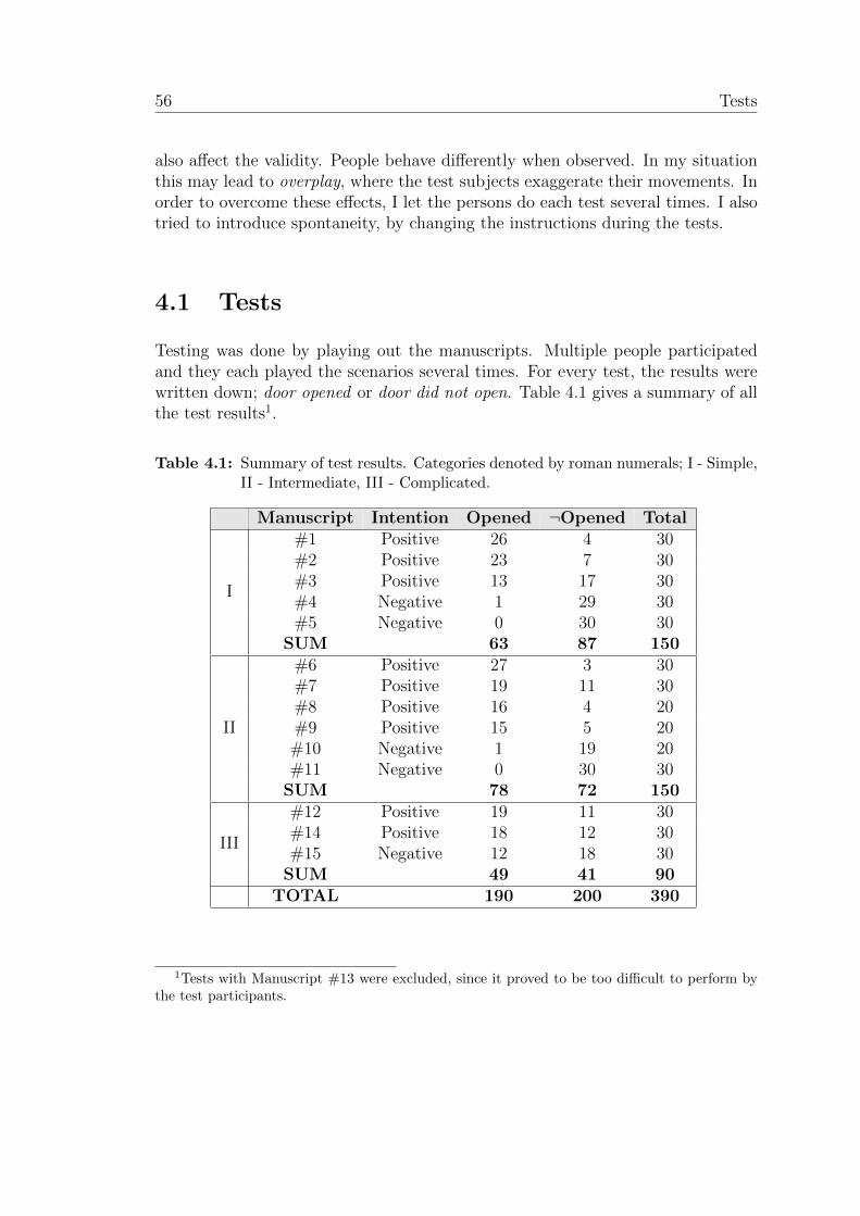
ii
“report” — 2011/6/20 — 15:25 — page 56 — #70 ii
ii
ii
56 Tests
also affect the validity. People behave differently when observed. In my situationthis may lead to overplay, where the test subjects exaggerate their movements. Inorder to overcome these effects, I let the persons do each test several times. I alsotried to introduce spontaneity, by changing the instructions during the tests.
4.1 Tests
Testing was done by playing out the manuscripts. Multiple people participatedand they each played the scenarios several times. For every test, the results werewritten down; door opened or door did not open. Table 4.1 gives a summary of allthe test results1.
Table 4.1: Summary of test results. Categories denoted by roman numerals; I - Simple,II - Intermediate, III - Complicated.
Manuscript Intention Opened ¬Opened Total#1 Positive 26 4 30#2 Positive 23 7 30#3 Positive 13 17 30#4 Negative 1 29 30#5 Negative 0 30 30
I
SUM 63 87 150#6 Positive 27 3 30#7 Positive 19 11 30#8 Positive 16 4 20#9 Positive 15 5 20#10 Negative 1 19 20#11 Negative 0 30 30
II
SUM 78 72 150#12 Positive 19 11 30#14 Positive 18 12 30#15 Negative 12 18 30
III
SUM 49 41 90TOTAL 190 200 390
1Tests with Manuscript #13 were excluded, since it proved to be too difficult to perform bythe test participants.
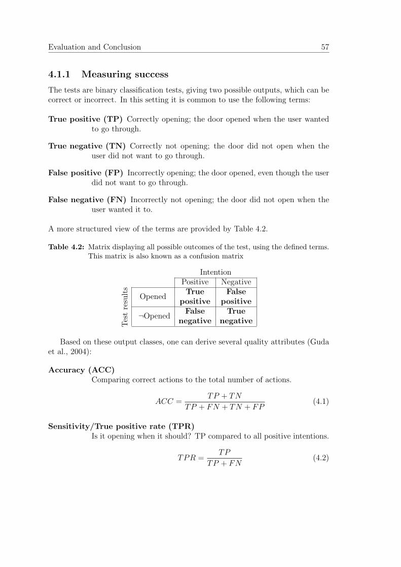
ii
“report” — 2011/6/20 — 15:25 — page 57 — #71 ii
ii
ii
Evaluation and Conclusion 57
4.1.1 Measuring success
The tests are binary classification tests, giving two possible outputs, which can becorrect or incorrect. In this setting it is common to use the following terms:
True positive (TP) Correctly opening; the door opened when the user wantedto go through.
True negative (TN) Correctly not opening; the door did not open when theuser did not want to go through.
False positive (FP) Incorrectly opening; the door opened, even though the userdid not want to go through.
False negative (FN) Incorrectly not opening; the door did not open when theuser wanted it to.
A more structured view of the terms are provided by Table 4.2.
Table 4.2: Matrix displaying all possible outcomes of the test, using the defined terms.This matrix is also known as a confusion matrix
IntentionPositive Negative
OpenedTrue False
positive positive
¬OpenedFalse True
Tes
tre
sult
s
negative negative
Based on these output classes, one can derive several quality attributes (Gudaet al., 2004):
Accuracy (ACC)Comparing correct actions to the total number of actions.
ACC =TP + TN
TP + FN + TN + FP(4.1)
Sensitivity/True positive rate (TPR)Is it opening when it should? TP compared to all positive intentions.
TPR =TP
TP + FN(4.2)
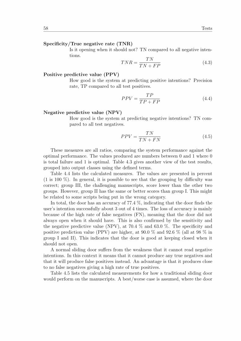
ii
“report” — 2011/6/20 — 15:25 — page 58 — #72 ii
ii
ii
58 Tests
Specificity/True negative rate (TNR)Is it opening when it should not? TN compared to all negative inten-tions.
TNR =TN
TN + FP(4.3)
Positive predictive value (PPV)How good is the system at predicting positive intentions? Precisionrate, TP compared to all test positives.
PPV =TP
TP + FP(4.4)
Negative predictive value (NPV)How good is the system at predicting negative intentions? TN com-pared to all test negatives.
PPV =TN
TN + FN(4.5)
These measures are all ratios, comparing the system performance against theoptimal performance. The values produced are numbers between 0 and 1 where 0is total failure and 1 is optimal. Table 4.3 gives another view of the test results,grouped into output classes using the defined terms.
Table 4.4 lists the calculated measures. The values are presented in percent(1 is 100 %). In general, it is possible to see that the grouping by difficulty wascorrect; group III, the challenging manuscripts, score lower than the other twogroups. However, group II has the same or better scores than group I. This mightbe related to some scripts being put in the wrong category.
In total, the door has an accuracy of 77.4 %, indicating that the door finds theuser’s intention successfully about 3 out of 4 times. The loss of accuracy is mainlybecause of the high rate of false negatives (FN), meaning that the door did notalways open when it should have. This is also confirmed by the sensitivity andthe negative predictive value (NPV), at 70.4 % and 63.0 %. The specificity andpositive prediction value (PPV) are higher, at 90.0 % and 92.6 % (all at 98 % ingroup I and II). This indicates that the door is good at keeping closed when itshould not open.
A normal sliding door suffers from the weakness that it cannot read negativeintentions. In this context it means that it cannot produce any true negatives andthat it will produce false positives instead. An advantage is that it produces closeto no false negatives giving a high rate of true positives.
Table 4.5 lists the calculated measurements for how a traditional sliding doorwould perform on the manuscripts. A best/worse case is assumed, where the door
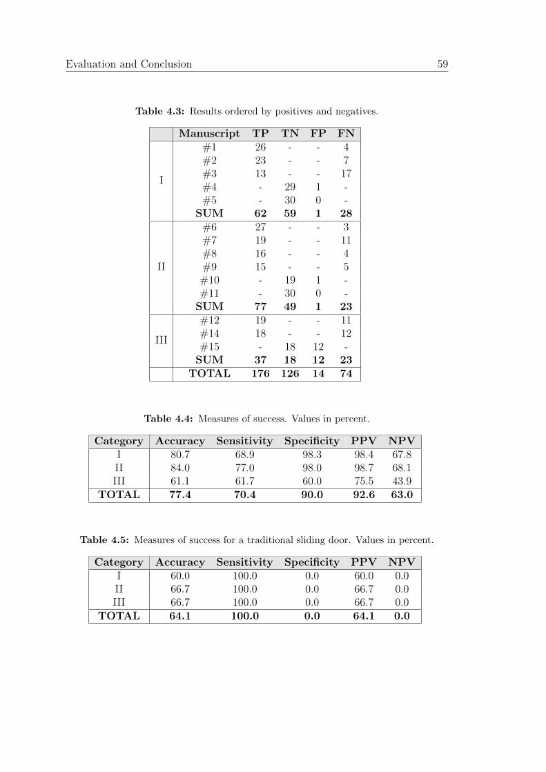
ii
“report” — 2011/6/20 — 15:25 — page 59 — #73 ii
ii
ii
Evaluation and Conclusion 59
Table 4.3: Results ordered by positives and negatives.
Manuscript TP TN FP FN#1 26 - - 4#2 23 - - 7#3 13 - - 17#4 - 29 1 -#5 - 30 0 -
I
SUM 62 59 1 28#6 27 - - 3#7 19 - - 11#8 16 - - 4#9 15 - - 5#10 - 19 1 -#11 - 30 0 -
II
SUM 77 49 1 23#12 19 - - 11#14 18 - - 12#15 - 18 12 -
III
SUM 37 18 12 23TOTAL 176 126 14 74
Table 4.4: Measures of success. Values in percent.
Category Accuracy Sensitivity Specificity PPV NPVI 80.7 68.9 98.3 98.4 67.8II 84.0 77.0 98.0 98.7 68.1III 61.1 61.7 60.0 75.5 43.9
TOTAL 77.4 70.4 90.0 92.6 63.0
Table 4.5: Measures of success for a traditional sliding door. Values in percent.
Category Accuracy Sensitivity Specificity PPV NPVI 60.0 100.0 0.0 60.0 0.0II 66.7 100.0 0.0 66.7 0.0III 66.7 100.0 0.0 66.7 0.0
TOTAL 64.1 100.0 0.0 64.1 0.0

ii
“report” — 2011/6/20 — 15:25 — page 60 — #74 ii
ii
ii
60 Tests
always opens, as long as there is movement within the sensor range. The resultsgive the expected outcome with a sensitivity of 100 % and specificity of 0 %. Withno true negatives, the negative predictive value is also 0 %. Since the door cannotproduce neither true nor false negatives, the accuracy measure becomes equivalentwith the positive predictive value. The accuracy of 64.1 % is then basically anindication of the distribution of positive/negative tests rather than the door’squality and is thereby not so useful as a general measure
(9 positive tests
14 tests= 64.3 %
).
However, it is possible to compare the two accuracy values, expressing that forthese tests an intention-aware door will have a higher accuracy.
Some of the tests gave negative outputs because the system either failed tolocate a person in the scene or to locate the points of interest. These results canbe related to limitations in the hardware and the software library componentsthat are out of my control, and thereby not related to the reasoning process. Analternative view can then be provided by removing these outcomes (both TN andFN). Tables 4.6 and 4.7 are updated to this view.
Table 4.6: Modified result table, alternative view. Negatives not related to reasoningprocess removed.
Manuscript TP TN FP FN#1 26 - - 0#2 23 - - 3#3 13 - - 7#4 - 22 1 -#5 - 23 0 -
I
SUM 62 45 1 10#6 27 - - 0#7 19 - - 5#8 16 - - 1#9 15 - - 2#10 - 19 1 -#11 - 30 0 -
II
SUM 77 49 1 8#12 19 - - 7#14 18 - - 8#15 - 15 12 -
III
SUM 37 15 12 15TOTAL 176 109 14 33
By removing the false negatives and the true negatives produced by limitationsto the system, the values of the quality measures change. A drop in false nega-
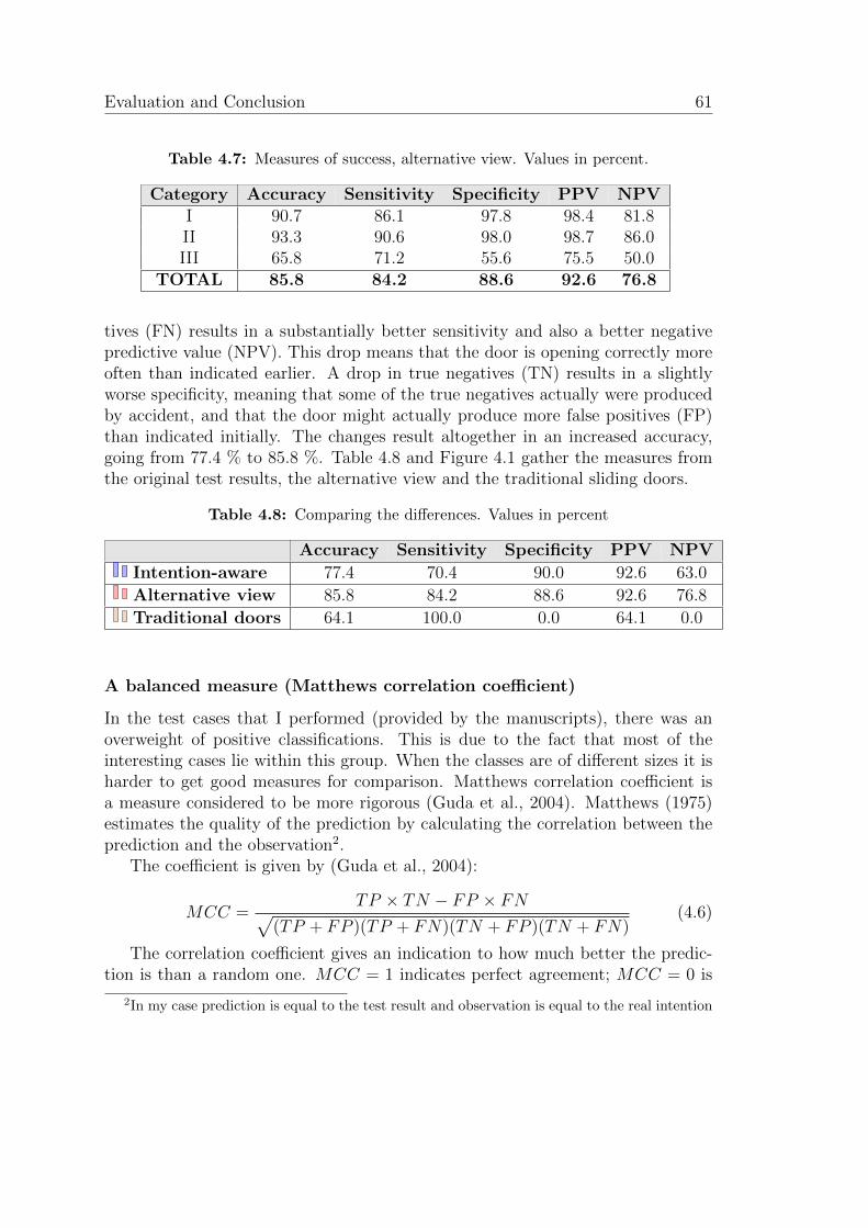
ii
“report” — 2011/6/20 — 15:25 — page 61 — #75 ii
ii
ii
Evaluation and Conclusion 61
Table 4.7: Measures of success, alternative view. Values in percent.
Category Accuracy Sensitivity Specificity PPV NPVI 90.7 86.1 97.8 98.4 81.8II 93.3 90.6 98.0 98.7 86.0III 65.8 71.2 55.6 75.5 50.0
TOTAL 85.8 84.2 88.6 92.6 76.8
tives (FN) results in a substantially better sensitivity and also a better negativepredictive value (NPV). This drop means that the door is opening correctly moreoften than indicated earlier. A drop in true negatives (TN) results in a slightlyworse specificity, meaning that some of the true negatives actually were producedby accident, and that the door might actually produce more false positives (FP)than indicated initially. The changes result altogether in an increased accuracy,going from 77.4 % to 85.8 %. Table 4.8 and Figure 4.1 gather the measures fromthe original test results, the alternative view and the traditional sliding doors.
Table 4.8: Comparing the differences. Values in percent
Accuracy Sensitivity Specificity PPV NPV
Intention-aware 77.4 70.4 90.0 92.6 63.0
Alternative view 85.8 84.2 88.6 92.6 76.8
Traditional doors 64.1 100.0 0.0 64.1 0.0
A balanced measure (Matthews correlation coefficient)
In the test cases that I performed (provided by the manuscripts), there was anoverweight of positive classifications. This is due to the fact that most of theinteresting cases lie within this group. When the classes are of different sizes it isharder to get good measures for comparison. Matthews correlation coefficient isa measure considered to be more rigorous (Guda et al., 2004). Matthews (1975)estimates the quality of the prediction by calculating the correlation between theprediction and the observation2.
The coefficient is given by (Guda et al., 2004):
MCC =TP × TN − FP × FN√
(TP + FP )(TP + FN)(TN + FP )(TN + FN)(4.6)
The correlation coefficient gives an indication to how much better the predic-tion is than a random one. MCC = 1 indicates perfect agreement; MCC = 0 is
2In my case prediction is equal to the test result and observation is equal to the real intention
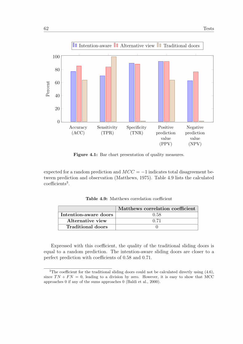
ii
“report” — 2011/6/20 — 15:25 — page 62 — #76 ii
ii
ii
62 Tests
Accuracy(ACC)
Sensitivity(TPR)
Specificity(TNR)
Positiveprediction
value(PPV)
Negativeprediction
value(NPV)
0
20
40
60
80
100
Per
cent
Intention-aware Alternative view Traditional doors
Figure 4.1: Bar chart presentation of quality measures.
expected for a random prediction and MCC = −1 indicates total disagreement be-tween prediction and observation (Matthews, 1975). Table 4.9 lists the calculatedcoefficients3.
Table 4.9: Matthews correlation coefficient
Matthews correlation coefficientIntention-aware doors 0.58
Alternative view 0.71Traditional doors 0
Expressed with this coefficient, the quality of the traditional sliding doors isequal to a random prediction. The intention-aware sliding doors are closer to aperfect prediction with coefficients of 0.58 and 0.71.
3The coefficient for the traditional sliding doors could not be calculated directly using (4.6),since TN + FN = 0, leading to a division by zero. However, it is easy to show that MCCapproaches 0 if any of the sums approaches 0 (Baldi et al., 2000).
ii
“report” — 2011/6/20 — 15:25 — page 63 — #77 ii
ii
ii
Evaluation and Conclusion 63
4.2 Summary
In this project I have designed a model of features, human behavior and intentions.The model suggests a set of features that can be used to describe the interactionbetween a human being and an automated sliding door. The model also definessymbols representing value sets for the features. The symbols are then combinedin order to describe different events, mapping features to intentions. This modelprovides a framework guiding the capturing process as well as the reasoning pro-cess.
Further, I have designed a mechanism for capturing human movement andextracting the features as suggested by the model of features, human behavior andintentions. The solution components are based on research done within computervision, where different tools and algorithms were reviewed and evaluated. Partsof the suggested solution are provided as software libraries, while others had tobe implemented. The solution includes using an Xbox Kinect as a sensor device,and the OpenNI framework together with the middleware NITE for Human bodytracking and skeletal joint extraction.
A reasoning mechanism was designed, that utilizes the designed model in orderto reach a conclusion about the intention of a human interacting with the door.Different reasoning techniques were reviewed in context of the sliding doors prob-lem. Based on the review I suggest using rule-based reasoning. By using the eventsdescribed in the model and by giving values to the different symbols I was able toform the rules for the reasoning process.
The designed mechanisms were put together in an implementation in C/C++comprising depth and RGB image capture, body tracking, user handling and fea-ture extraction, rule-based reasoning and door control.
A motorized sliding door was built, together with a door controller allowing acomputer to interface with the door, giving open and close commands.
Finally, the door was tested both through a live demo and a laboratory style,structured observation. The door proved a superior performance to the tradi-tional sliding doors when it came to identifying negative intentions, thus reducingthe number of false positives drastically. However, both false positives and falsenegatives occurred, leaving room for improved accuracy.
With my solution I have managed to interpret the intention of a user interactingwith an automated sliding door. I have lifted the reasoning process to a symboliclevel, dealing with symbols and events easy to understand. Although the model islimited to a very specific domain, and the solution has got some limitations andweaknesses, this is a good starting point for further work.
ii
“report” — 2011/6/20 — 15:25 — page 64 — #78 ii
ii
ii
64 Discussion
4.3 Discussion
The final results showed that it is possible to improve the non-verbal commu-nication between humans and computers. By interpreting human intentions theautomated environment can understand its user in a better way. An automatedsliding door is just one example where miscommunication is present. By givingthe door controller the capability of understanding the behavior of its users, itis possible to reduce the number of cases where the door opens when it is notsupposed to.
Allowing the door controller to reason, will however introduce the possibilityof the door wrongly deciding not to open. Looking at the test results from mydoor one can see that the sensitivity was not very good (70.4 %), meaning thatthe door was not always opening when it should. This is also confirmed by thenegative predictive value, stating that just 63 % of the cases where the door didnot open were correct, and that 37 % were incorrect.
Some of the reasons for the low rates are related to limitations in the solutioncomponents and the setup. Together with the presented test results I also pre-sented an alternative view. This view excluded the cases where the system eitherdid not manage to detect any person in the scene or did not manage to startskeletal tracking of the person. In all these cases the door did not open because oflacking information.
The positioning of the sensor device (above the door) causes some of theselimitations. The Kinect provides a field of view of 47 vertically, and in order tocover the close range, the sensor had to be tilted downwards, limiting the maximumdepth (see Figure 3.2, page 31 for details). In cases where the head was out of rangeor arms were partly or fully occluded, the system often failed initiating trackingof the skeleton. I also observed that the skeletal tracking often failed initiatingwhen the sensor did not detect both of the user’s arms in a more or less normalposition. Carrying bags or using cell phones often created problems.
If I had lowered the sensor, both the depth and height of the field of viewcould have been improved. This would probably have eased the skeletal trackinginitiation problems. However, this would not in any way be an ideal position fora sensor as it now would be in the middle of the door opening. A solution to thiscould have been to put the sensor next to the door. This creates a blind spot onthe opposite side of the door, but by combining multiple sensors one could expandthe field of view.
The alternative view gave more promising results. With a set of false negatives(but also true negatives) removed, the accuracy increased. In the breakdown ofthe test results (Table 4.7, page 61) it is possible to see that the accuracy waslowest in Category III. This category includes some test cases that are difficult todetermine (late change of mind) as well as giving few relevant feature sets (short
ii
“report” — 2011/6/20 — 15:25 — page 65 — #79 ii
ii
ii
Evaluation and Conclusion 65
time before user is in the sensor’s blind spot). The decision about opening thedoor must be taken at a certain time; if the user changes his mind after this, thereis no way of avoiding a false positive. In addition, if the sensor was able to coverthe whole area in front of the door, without any blind spots under the camera,the tracking could have provided more feature sets, and the reasoning in the closecases could have been strengthened.
It is hard to prove whether better results can be achieved only by adjustingthe values of the symbols, or if it is necessary to add extra symbols, rules, andpossibly even extra features. It would be interesting to see if a machine learningprocess could find better values (and rules) for the reasoning, i.e. using decisiontree learning.
The tests revealed a bug in the third-party software libraries, occurring whensome of the tracking points was occluded (especially when the user walked throughthe door), leading to a segmentation violation, crashing the program. Since themiddleware is only provided as binaries, I was not able to track down this bug.Improving the routines for skeletal tracking under occlusion is also impossiblewithout having source code available. These aspects make it less desirable to useoff the shelf components.
Regardless of what components that are used, it is possible to improve thecommunication between humans and computers by analyzing intentions. One ofthe main challenges is to provide the system with “perfect” data, covering everyangle and every movement, even under partial occlusion. When testing the systemwith multiple actors I used two persons. Dealing with crowds of people provideeven harder challenges, in this case it would be almost impossible to track eachand every joint, inferring the underlying intentions.
4.4 Future Work
The solution proposed in this thesis is by no means the answer to the complex prob-lem of interpreting human intentions. It is more of a simple, conceptual approachof merging two disciplines within computer science and artificial intelligence.
As mentioned in the Discussion, it could have been useful to explore the valuesof the symbols using machine learning. By learning the classification one could tryto find an optimal set of values that might improve the accuracy, in general andespecially in the more challenging cases. In my work the values were hard coded,and adjusted manually according to the limitations of the equipment and by trialand error.
Another interesting approach would be to use probabilistic tools, i.e. Markovmodels and Kalman filters, in order to predict the user’s next move, but also inorder to deal with noise and occlusion.
ii
“report” — 2011/6/20 — 15:25 — page 66 — #80 ii
ii
ii
66 Future Work
OpenNI provides a good framework, well suited for human-computer interac-tion. Using this, it is possible to add multiple sensors. This could remove some ofthe limitations that I experienced using only one Kinect, being bound to position-ing it above the door, tilted downwards. Experimenting with the positioning ofthe sensor(s) or even adding different types of sensors could give valuable resultsproviding better tracking abilities. It would also be possible to develop alternativeimplementations to the proprietary NITE middleware. This will, as well as remov-ing bugs, allow you to control the tracking on a deeper level. This implementationscan then more closely handle intentions and improve the occlusion issues describedearlier.
In the last days of my thesis writing, Microsoft released their official develop-ment kit (SDK) for use with the Xbox Kinect sensor. It might be desirable tolook into this if planning to continue working with a Kinect sensor. This howeverrequires the use of Windows 7.
It is also desirable to transfer this solution to other problem areas. My solu-tion is just a small step towards what could be much larger. Knowing the user’sintention, without explicitly asking for it, is very helpful. Transferred to othertasks, this can open a wide range of possibilities. Systems can improve their func-tionality and efficiency greatly by reading the user’s intentions, and acting uponthem. Operating on a symbolic level also allows the systems to give reasonableexplanations for their choices.
ii
“report” — 2011/6/20 — 15:25 — page 67 — #81 ii
ii
ii
Bibliography
Aamodt, A. and Plaza, E. (1994). Case-based reasoning: Foundational is-sues, methodological variations, and system approaches. AI Communications,7(1):39–59.
Amano, M., Hironaka, D., Oda, S., Capi, G., and Yokota, M. (2005). Linguisticinterpretation of human motion based on mental image directed semantic theory.In Advanced Information Networking and Applications, 2005. AINA 2005. 19thInternational Conference on, volume 1, pages 139–144.
Baldi, P., Brunak, S., Chauvin, Y., Andersen, C. A. F., and Nielsen, H. (2000).Assessing the accuracy of prediction algorithms for classification: an overview.Bioinformatics, 16(5):412–424.
Bilgic, B., Horn, B., and Masaki, I. (2010). Fast human detection with cascadedensembles on the GPU. In Intelligent Vehicles Symposium (IV), 2010 IEEE,pages 325–332.
Caillette, F. and Howard, T. (2004). Real-Time Markerless Human Body Track-ing Using Colored Voxels and 3-D Blobs. Third IEEE and ACM InternationalSymposium on Mixed and Augmented Reality, pages 266–267.
Corazza, S., Mundermann, L., and Andriacchi, T. (2007). A framework for thefunctional identification of joint centers using markerless motion capture, vali-dation for the hip joint. Journal of biomechanics, 40(15):3510–3515.
Dalal, N. and Triggs, B. (2005). Histograms of oriented gradients for humandetection. In Computer Vision and Pattern Recognition, 2005. CVPR 2005.IEEE Computer Society Conference on, volume 1, pages 886–893. IEEE.
Giosan, I., Nedevschi, S., and Bota, S. (2009). Real time stereo vision basedpedestrian detection using full body contours. 2009 IEEE 5th InternationalConference on Intelligent Computer Communication and Processing, pages 79–86.
ii
“report” — 2011/6/20 — 15:25 — page 68 — #82 ii
ii
ii
68 Bibliography
Guda, C., Fahy, E., and Subramaniam, S. (2004). MITOPRED: a genome-scalemethod for prediction of nucleus-encoded mitochondrial proteins. Bioinformat-ics, 20(11):1785–1794.
Guerra-Filho, G. and Aloimonos, Y. (2006). A Sensory-Motor Language for Hu-man Activity Understanding. In Humanoid Robots, 2006 6th IEEE-RAS Inter-national Conference on, pages 69–75.
Horaud, R., Niskanen, M., Dewaele, G., and Boyer, E. (2009). Human MotionTracking by Registering an Articulated Surface to 3D Points and Normals. Jour-nal of Pharmacy and Pharmacology, 61(7):27–31.
Intel (2007). Power Supply Design Guide for Desktop Platform Form Factors. IntelCorporation. http://www.formfactors.org/developer%5Cspecs%5CPSU_DG_
rev_1_1.pdf (accessed 07.06.2011).
Jia, H.-X. and Zhang, Y.-J. (2007). Fast human detection by boosting histogramsof oriented gradients. In Image and Graphics, 2007. ICIG 2007. Fourth Inter-national Conference on, pages 683–688.
Kofod-Petersen, A., Wegener, R., and Cassens, J. (2009). Closed doors – modellingintention in behavioural interfaces. In Kofod-Petersen, A., Langseth, H., andGundersen, O. E., editors, Proceedings of the first Norwegian Artificial Intelli-gence Symposium, pages 93–102, Trondheim, Norway. Tapir Akademiske Forlag.
Langdridge, D. (2006). Psykologisk forskningsmetode. Tapir Akademisk Forlag.Norwegian translation of Introduction to Research Methods and Data Analysisin Psychology 01.
Lienhart, R. and Maydt, J. (2002). An extended set of Haar-like features for rapidobject detection. In Image Processing. 2002. Proceedings. 2002 InternationalConference on, volume 1, pages 900–903.
Lillywhite, K., Lee, D.-J., and Zhang, D. (2009). Real-time human detection usinghistograms of oriented gradients on a GPU. In Applications of Computer Vision(WACV), 2009 Workshop on, pages 1–6.
Martinec, R. (2001). Interpersonal resources in action. Semiotica, 2001(135):117–145.
Matthews, B. W. (1975). Comparison of the predicted and observed secondarystructure of T4 phage lysozyme. Biochimica et Biophysica Acta (BBA) - ProteinStructure, 405(2):442–451.
ii
“report” — 2011/6/20 — 15:25 — page 69 — #83 ii
ii
ii
Bibliography 69
Mitchell, T. (1997). Machine Learning. McGraw Hill.
Moore, A. R. (2008). Surgical teams in action: a contextually sensitive approachto modelling body alignment and interpersonal engagement.
OpenNI User Guide (2010). OpenNI User Guide. http://www.openni.org/
images/stories/pdf/OpenNI_UserGuide.pdf (accessed 13.04.2011).
Oral, M. and Deniz, U. (2007). Centre of mass model – A novel approach tobackground modelling for segmentation of moving objects. Image and VisionComputing, 25(8):1365–1376.
Russell, S. and Norvig, P. (2009). Artificial Intelligence: a Modern Approach.Prentice hall.
Sheldon, R. (2008a). Controlling inductive devices. http://www.
relaycontrollers.com/Relay/Device/A0009 (accessed 06.04.2011).
Sheldon, R. (2008b). Important notice. http://www.relaycontrollers.com/i.
htm (accessed 06.04.2011).
Sonka, M., Hlavac, V., and Boyle, R. (2008). Image processing, analysis, andmachine vision. Thomson.
Sugano, H., Miyamoto, R., and Nakamura, Y. (2010). Optimized parallel im-plementation of pedestrian tracking using HOG features on GPU. In Ph.D.Research in Microelectronics and Electronics (PRIME), 2010 Conference on,pages 1–4.
Toya, A., Hu, Z., Yoshida, T., Uchimura, K., Kubota, H., and Ono, M. (2008).Pedestrian recognition using stereo vision and histogram of oriented gradients.In Vehicular Electronics and Safety, 2008. ICVES 2008. IEEE InternationalConference on, pages 57–62.
Viola, P. and Jones, M. (2001). Rapid object detection using a boosted cascadeof simple features. In Computer Vision and Pattern Recognition, 2001. CVPR2001. Proceedings of the 2001 IEEE Computer Society Conference on, volume 1,pages 511–518.
Wang, Q. J. and Zhang, R. B. (2008). LPP-HOG: A new local image descriptor forfast human detection. In Knowledge Acquisition and Modeling Workshop, 2008.KAM Workshop 2008. IEEE International Symposium on, pages 640–643.

ii
“report” — 2011/6/20 — 15:25 — page 70 — #84 ii
ii
ii
70 Bibliography
Zhu, Q., Yeh, M., Cheng, K., and Avidan, S. (2006). Fast human detectionusing a cascade of histograms of oriented gradients. In Computer Vision andPattern Recognition, 2006 IEEE Computer Society Conference on, volume 2,pages 1491–1498. IEEE.

ii
“report” — 2011/6/20 — 15:25 — page 71 — #85 ii
ii
ii
Appendices

ii
“report” — 2011/6/20 — 15:25 — page 72 — #86 ii
ii
ii

ii
“report” — 2011/6/20 — 15:25 — page 73 — #87 ii
ii
ii
Appendix A
NSD
NSD (Norwegian Social Science Data Services) is the organ for norwegian univer-sities, that handles some of the responsibility delegated by the Data Inspectorateon issues concerning personal information and privacy. Because of my usage of acamera in a situation that involved other people, I had to notify this organ andget an approval that allowed me to collect the type of data I needed in order totest the performance of my door.
A.1 Notification
This notification is a print out of the electronically submitted notification form.The notification gives detailed specification of the personal information relatedactivities.

ii
“report” — 2011/6/20 — 15:25 — page 74 — #88 ii
ii
ii
74 Notification

ii
“report” — 2011/6/20 — 15:25 — page 75 — #89 ii
ii
ii
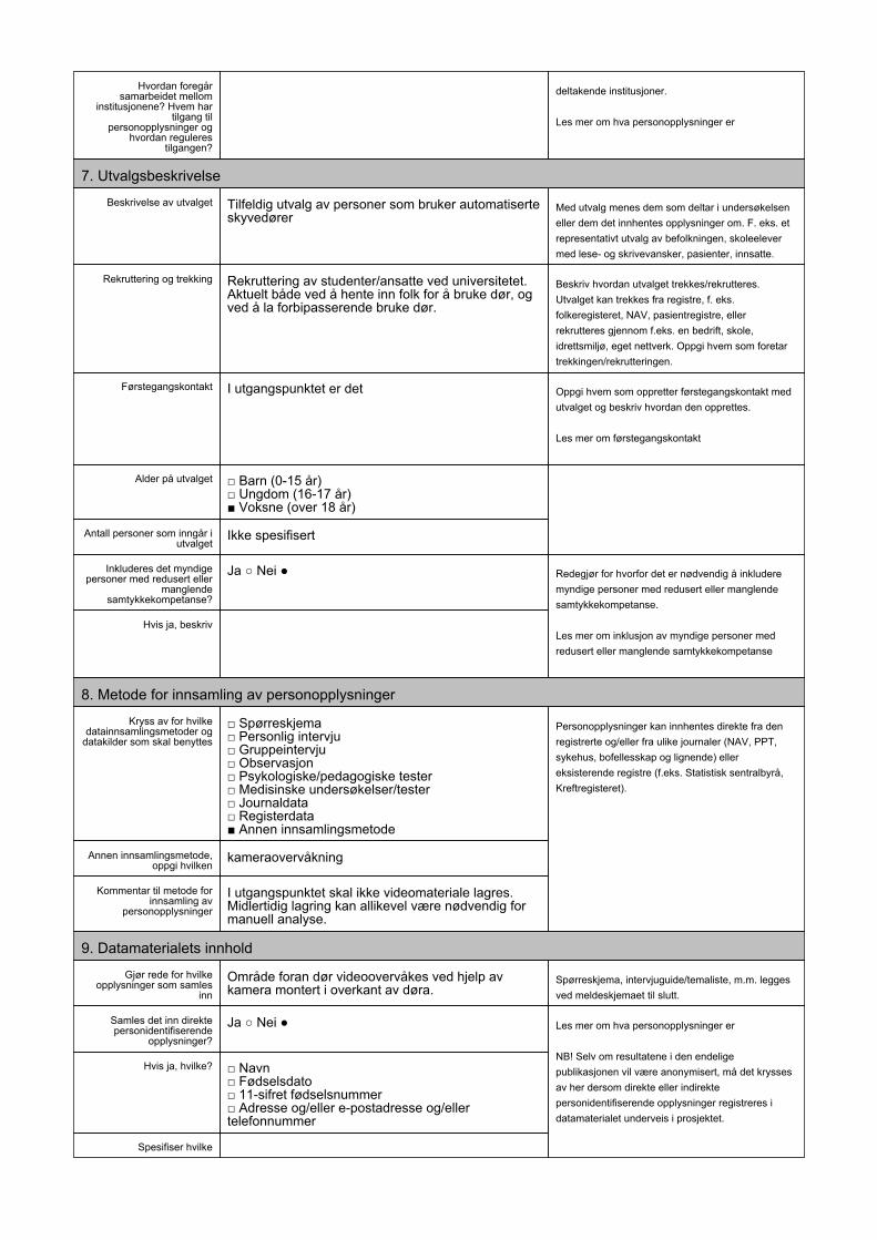
ii
“report” — 2011/6/20 — 15:25 — page 76 — #90 ii
ii
ii
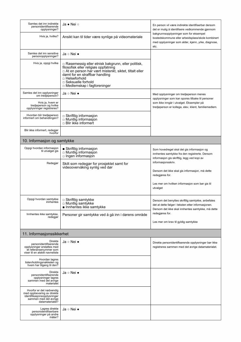
ii
“report” — 2011/6/20 — 15:25 — page 77 — #91 ii
ii
ii
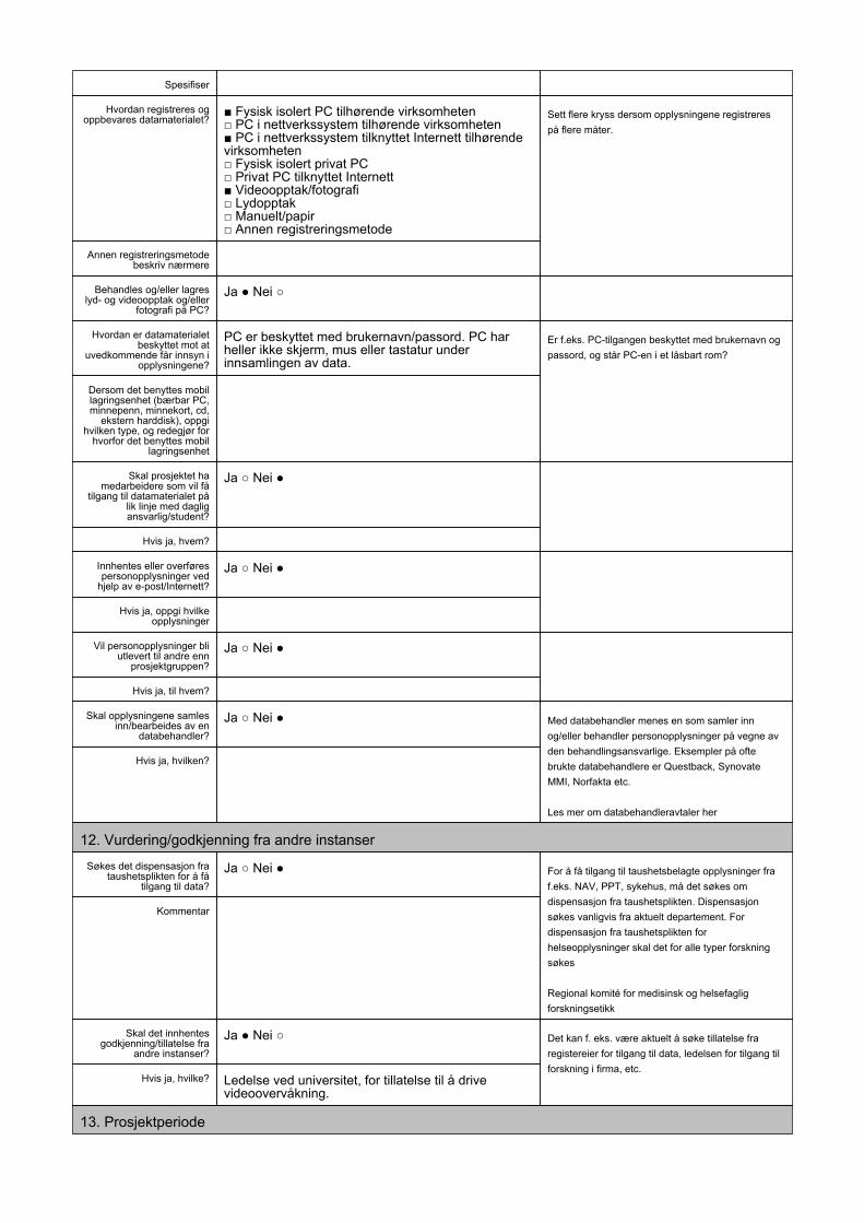
ii
“report” — 2011/6/20 — 15:25 — page 78 — #92 ii
ii
ii
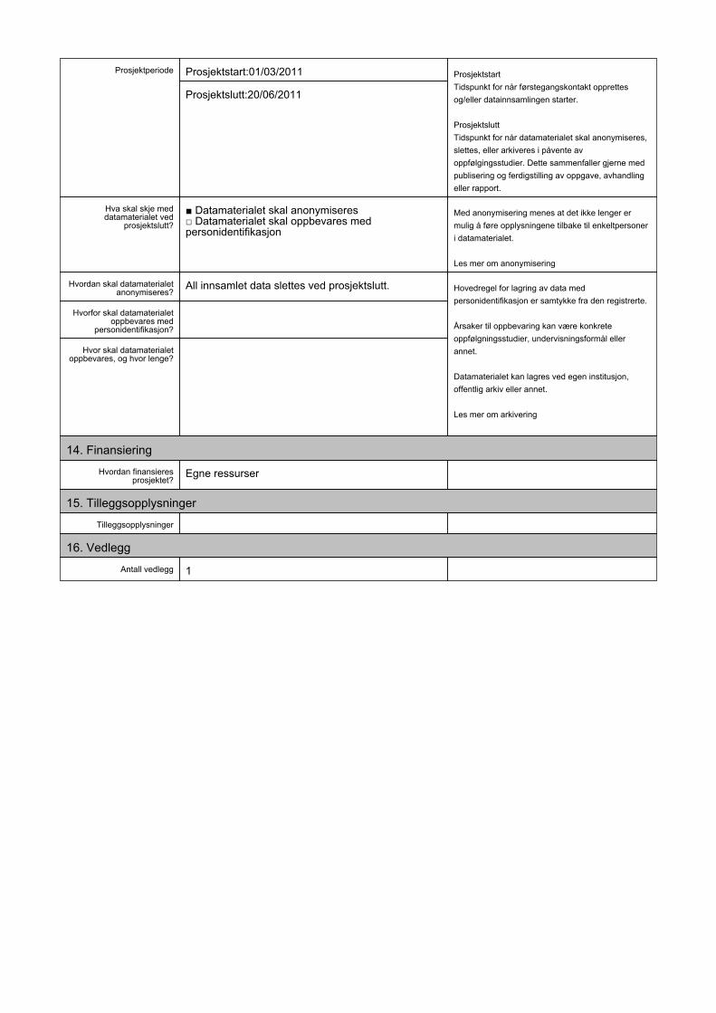
ii
“report” — 2011/6/20 — 15:25 — page 79 — #93 ii
ii
ii

ii
“report” — 2011/6/20 — 15:25 — page 80 — #94 ii
ii
ii
80 Notification

ii
“report” — 2011/6/20 — 15:25 — page 81 — #95 ii
ii
ii
NSD 81
A.2 Concession
This section includes the response from NSD allowing me to collect the data asrequested.

ii
“report” — 2011/6/20 — 15:25 — page 82 — #96 ii
ii
ii
82 Concession

ii
“report” — 2011/6/20 — 15:25 — page 83 — #97 ii
ii
ii

ii
“report” — 2011/6/20 — 15:25 — page 84 — #98 ii
ii
ii

ii
“report” — 2011/6/20 — 15:25 — page 85 — #99 ii
ii
ii
NSD 85
A.3 Consent
When collecting personal data, it is important that this is done with the consentof the involved persons. This section includes the poster informing the test usersabout the collection and handling of data.

ii
“report” — 2011/6/20 — 15:25 — page 86 — #100 ii
ii
ii
86 Consent

ii
“report” — 2011/6/20 — 15:25 — page 87 — #101 ii
ii
ii
KAMERA-OVERVÅKNING
Prosjekt: Intensjons-basert dørDenne døra er en del av et masterprosjekt, som har som formål å konstruere en dør som responderer på ditt ønske om å gå gjennom den.
Du er velkommen til å gå gjennom døra, og/eller bevege deg i området rundt døra for å teste hvorvidt den faktisk åpner seg når du skal gå gjennom den.
For å muliggjøre dette er døra utstyrt med kamera og datamaskin som analyserer ditt bevegelsesmønster i området rundt den.
SamtykkeVed å gå inn i området samtykker du i at du blir video-overvåket. Video brukes direkte av systemet for å åpne døren. Det kan være nødvendig å ta vare på video for evaluering av dørens prestasjon. Alle innsamlede data vil bli slettet ved prosjektslutt (juni 2011).
John Sverre Solem! Anders [email protected]! [email protected]! Veileder

ii
“report” — 2011/6/20 — 15:25 — page 88 — #102 ii
ii
ii
88 Consent
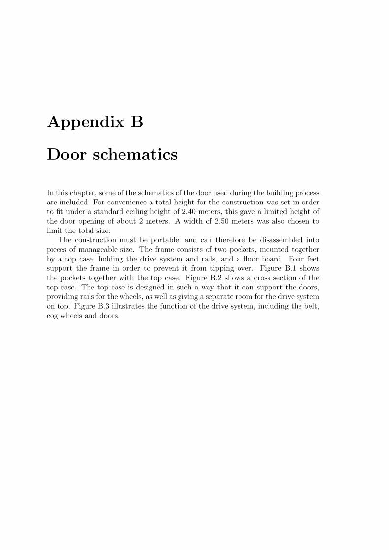
ii
“report” — 2011/6/20 — 15:25 — page 89 — #103 ii
ii
ii
Appendix B
Door schematics
In this chapter, some of the schematics of the door used during the building processare included. For convenience a total height for the construction was set in orderto fit under a standard ceiling height of 2.40 meters, this gave a limited height ofthe door opening of about 2 meters. A width of 2.50 meters was also chosen tolimit the total size.
The construction must be portable, and can therefore be disassembled intopieces of manageable size. The frame consists of two pockets, mounted togetherby a top case, holding the drive system and rails, and a floor board. Four feetsupport the frame in order to prevent it from tipping over. Figure B.1 showsthe pockets together with the top case. Figure B.2 shows a cross section of thetop case. The top case is designed in such a way that it can support the doors,providing rails for the wheels, as well as giving a separate room for the drive systemon top. Figure B.3 illustrates the function of the drive system, including the belt,cog wheels and doors.
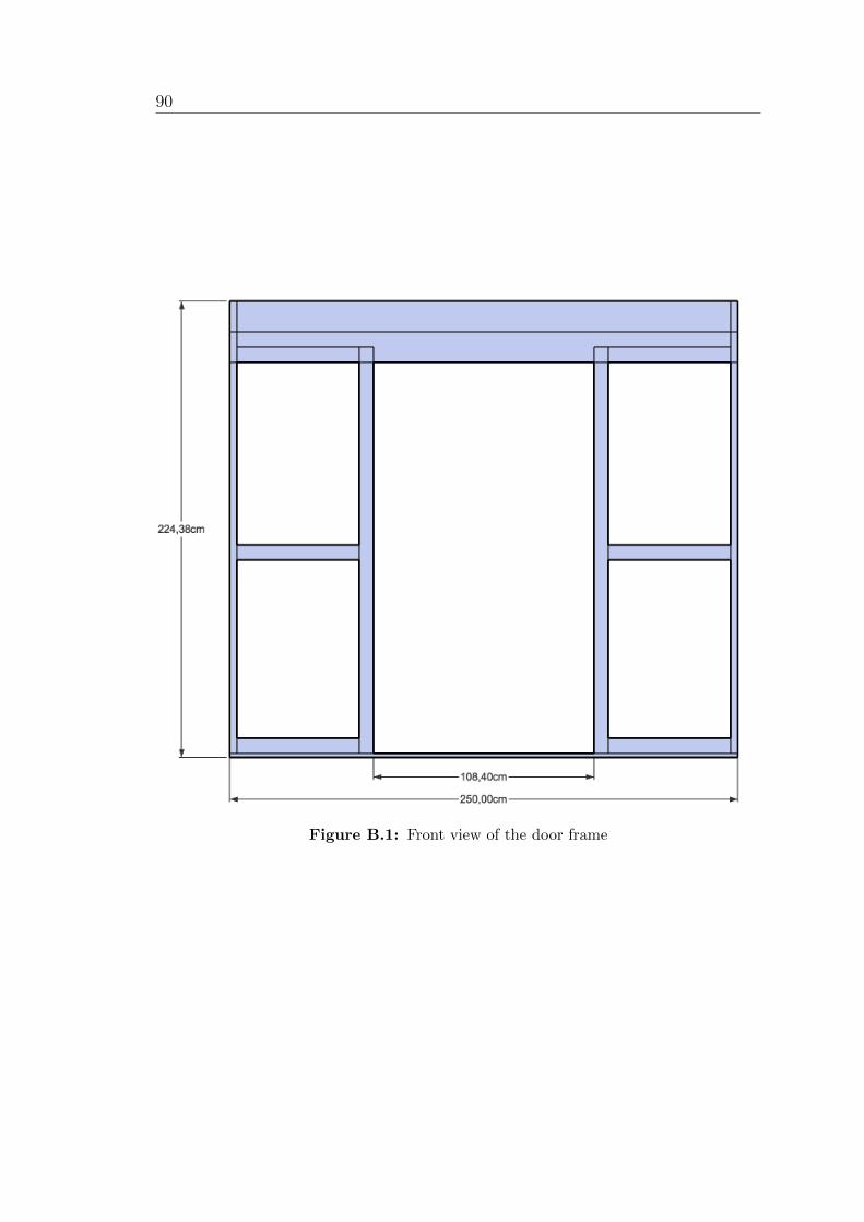
ii
“report” — 2011/6/20 — 15:25 — page 90 — #104 ii
ii
ii
90
Figure B.1: Front view of the door frame
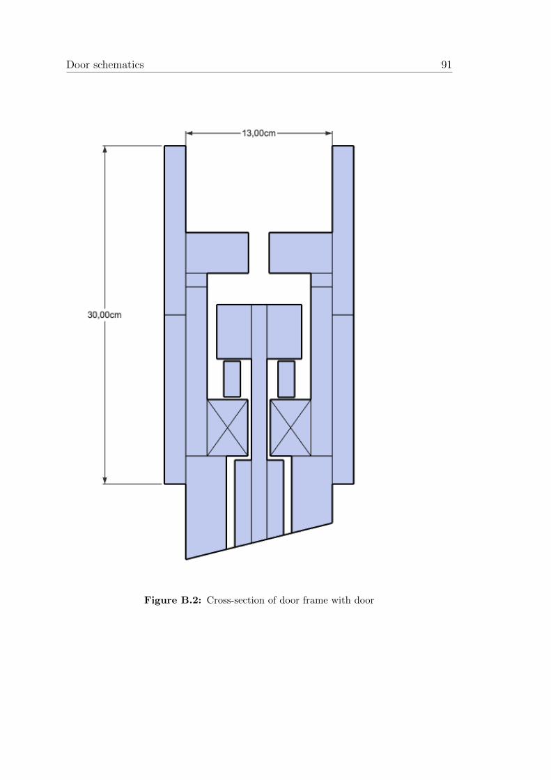
ii
“report” — 2011/6/20 — 15:25 — page 91 — #105 ii
ii
ii
Door schematics 91
Figure B.2: Cross-section of door frame with door
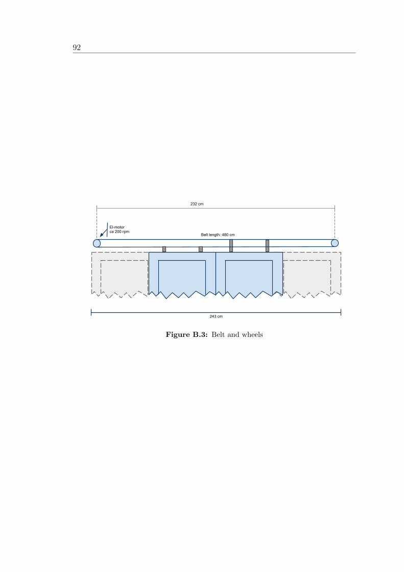
ii
“report” — 2011/6/20 — 15:25 — page 92 — #106 ii
ii
ii
92
Figure B.3: Belt and wheels
ii
“report” — 2011/6/20 — 15:25 — page 93 — #107 ii
ii
ii
Appendix C
Manuscripts
The manuscripts are written to provide a systematic approach to the testing ofthe sliding door. When testing the door, it is important to get a broad perspectivecovering some odd cases as well as the most frequently used cases. Random usagecould also have provided results, but then you lose control of which situations thatare played out, and the width of the cases is not guaranteed within a reasonableamount of time. The manuscripts in this section are written to cover what may beconsidered as normal use, bordering to abnormal. They are grouped in categoriesaccording to the challenge they provide. The manuscripts cover both positivecases, where the user wants to go through the door, and negative cases wherethe user does not want to go through the door. For all manuscripts the followingparameters are defined:
Category The challenge the case poses to the system – Simple, Intermedi-ate, Challenging.
Actors The number of actors involved in the scene.
Intention The actors intention of walking through the door – Positive orNegative.
Speed How the walk is done – Normal or Fast
Acceleration How the speed changes throughout the case
Path The direction of walking – Straight, Changing etc.
Description Detailed instructions on how the case must be played.
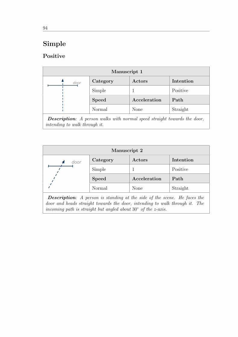
ii
“report” — 2011/6/20 — 15:25 — page 94 — #108 ii
ii
ii
94
Simple
Positive
Manuscript 1
Category Actors Intention
Simple 1 Positive
Speed Acceleration Path
Normal None Straight
Description: A person walks with normal speed straight towards the door,intending to walk through it.
Manuscript 2
Category Actors Intention
Simple 1 Positive
Speed Acceleration Path
door
door door
door door
Normal None Straight
Description: A person is standing at the side of the scene. He faces thedoor and heads straight towards the door, intending to walk through it. Theincoming path is straight but angled about 30 of the z-axis.
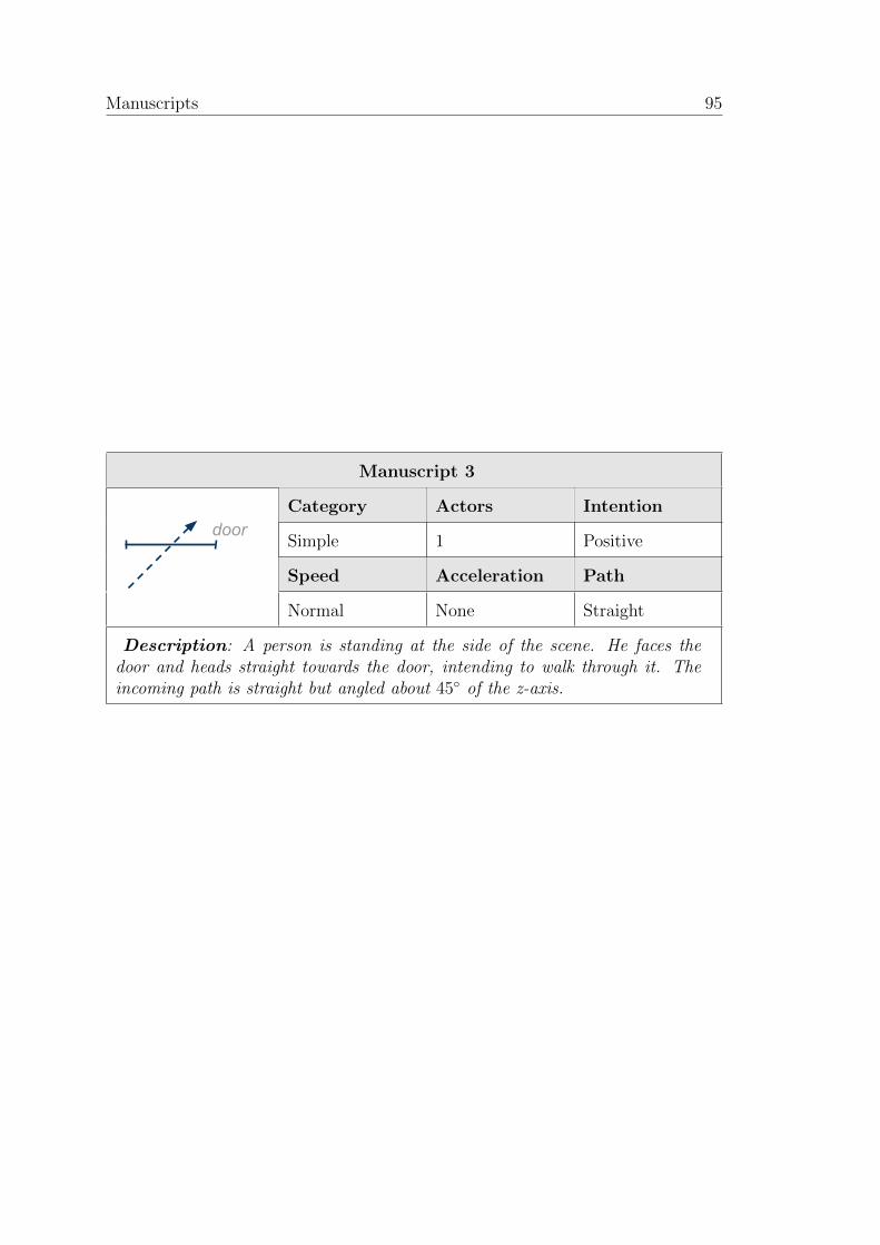
ii
“report” — 2011/6/20 — 15:25 — page 95 — #109 ii
ii
ii
Manuscripts 95
Manuscript 3
Category Actors Intention
Simple 1 Positive
Speed Acceleration Path
door
Normal None Straight
Description: A person is standing at the side of the scene. He faces thedoor and heads straight towards the door, intending to walk through it. Theincoming path is straight but angled about 45 of the z-axis.
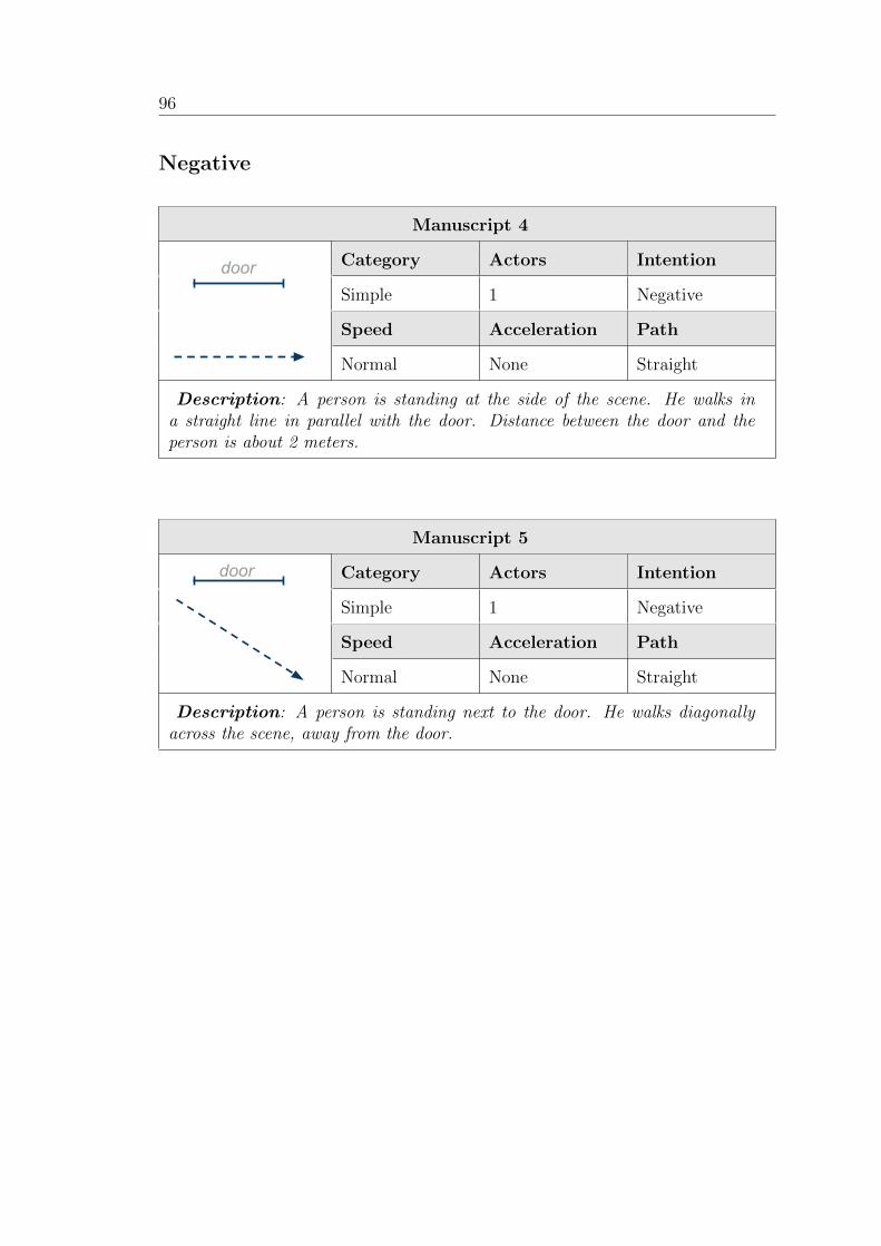
ii
“report” — 2011/6/20 — 15:25 — page 96 — #110 ii
ii
ii
96
Negative
Manuscript 4
Category Actors Intention
Simple 1 Negative
Speed Acceleration Path
door
Normal None Straight
Description: A person is standing at the side of the scene. He walks ina straight line in parallel with the door. Distance between the door and theperson is about 2 meters.
Manuscript 5
Category Actors Intention
Simple 1 Negative
Speed Acceleration Path
door
Normal None Straight
Description: A person is standing next to the door. He walks diagonallyacross the scene, away from the door.
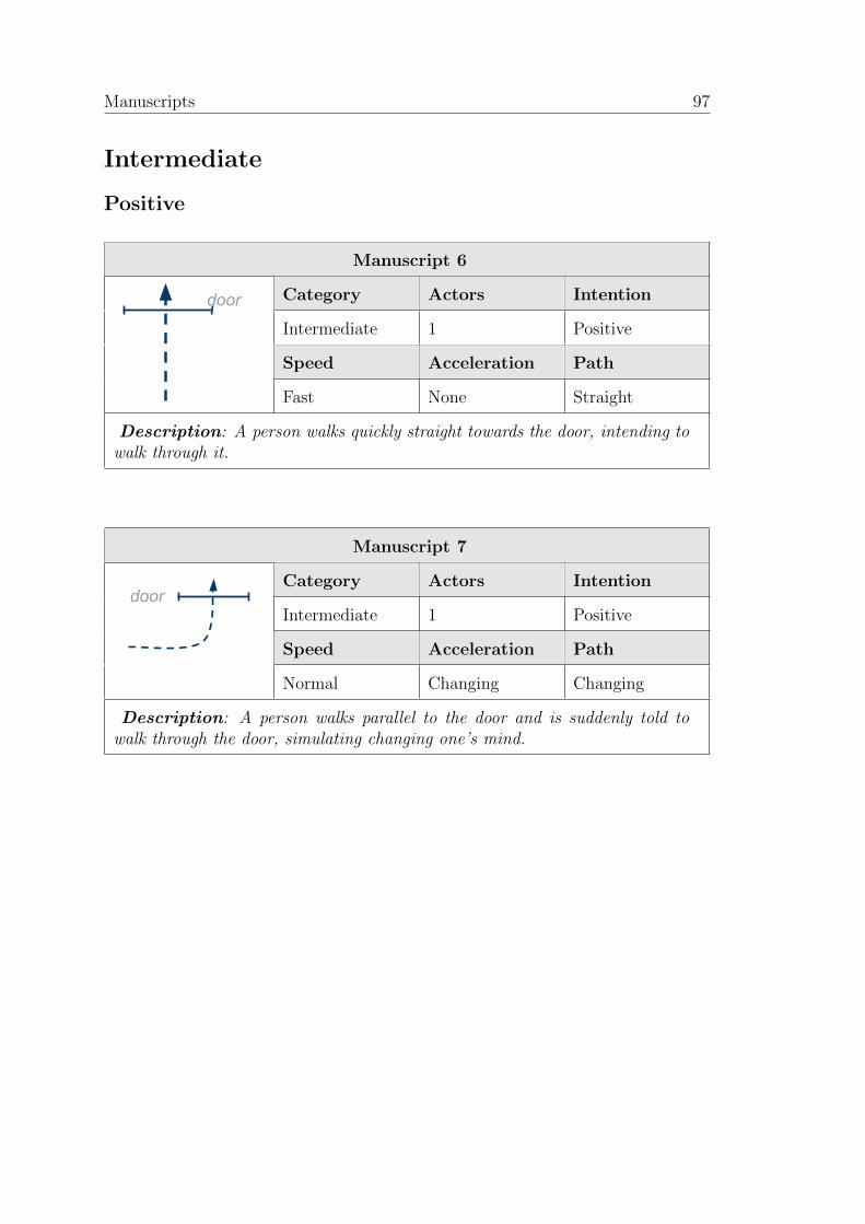
ii
“report” — 2011/6/20 — 15:25 — page 97 — #111 ii
ii
ii
Manuscripts 97
Intermediate
Positive
Manuscript 6
Category Actors Intention
Intermediate 1 Positive
Speed Acceleration Path
door
Fast None Straight
Description: A person walks quickly straight towards the door, intending towalk through it.
Manuscript 7
Category Actors Intention
Intermediate 1 Positive
Speed Acceleration Path
door
Normal Changing Changing
Description: A person walks parallel to the door and is suddenly told towalk through the door, simulating changing one’s mind.
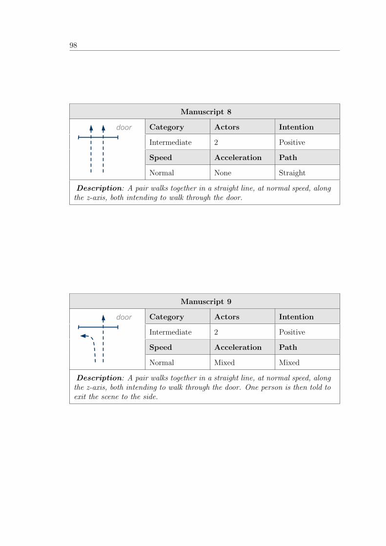
ii
“report” — 2011/6/20 — 15:25 — page 98 — #112 ii
ii
ii
98
Manuscript 8
Category Actors Intention
Intermediate 2 Positive
Speed Acceleration Path
door
Normal None Straight
Description: A pair walks together in a straight line, at normal speed, alongthe z-axis, both intending to walk through the door.
Manuscript 9
Category Actors Intention
Intermediate 2 Positive
Speed Acceleration Path
door
Normal Mixed Mixed
Description: A pair walks together in a straight line, at normal speed, alongthe z-axis, both intending to walk through the door. One person is then told toexit the scene to the side.
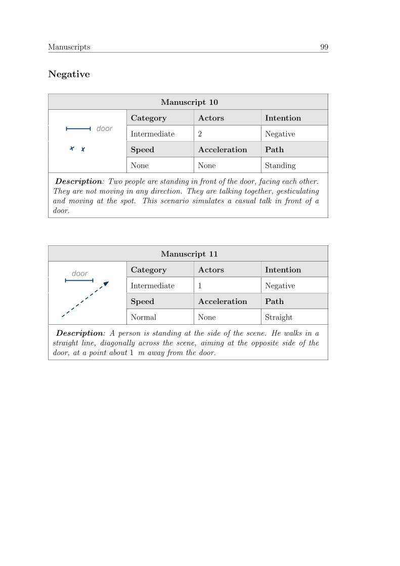
ii
“report” — 2011/6/20 — 15:25 — page 99 — #113 ii
ii
ii
Manuscripts 99
Negative
Manuscript 10
Category Actors Intention
Intermediate 2 Negative
Speed Acceleration Path
door
None None Standing
Description: Two people are standing in front of the door, facing each other.They are not moving in any direction. They are talking together, gesticulatingand moving at the spot. This scenario simulates a casual talk in front of adoor.
Manuscript 11
Category Actors Intention
Intermediate 1 Negative
Speed Acceleration Path
door
Normal None Straight
Description: A person is standing at the side of the scene. He walks in astraight line, diagonally across the scene, aiming at the opposite side of thedoor, at a point about 1 m away from the door.
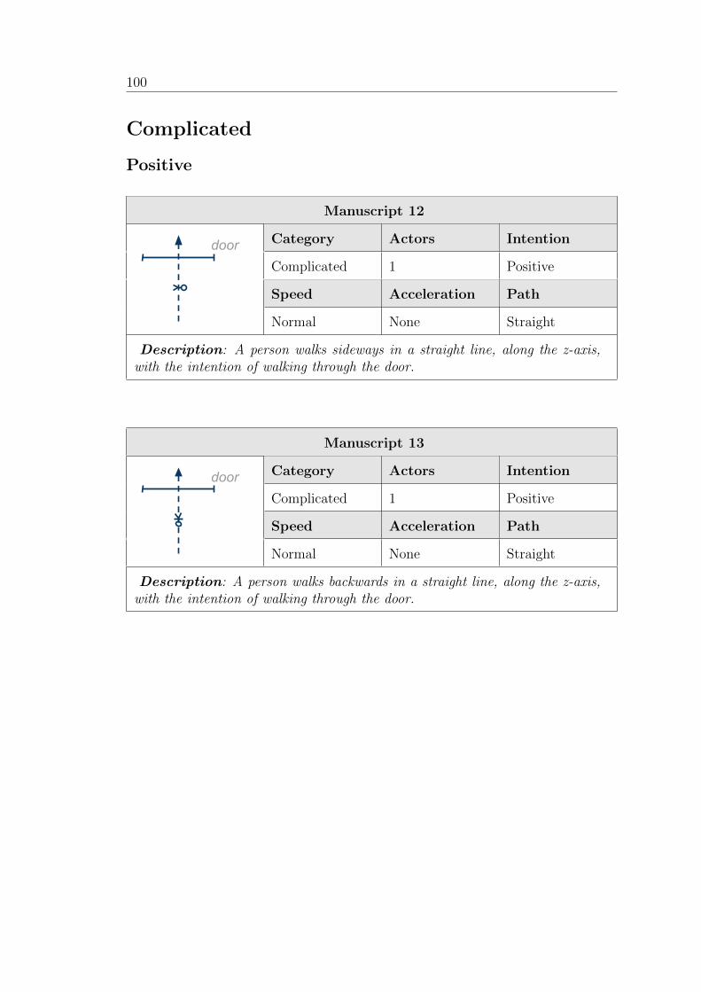
ii
“report” — 2011/6/20 — 15:25 — page 100 — #114 ii
ii
ii
100
Complicated
Positive
Manuscript 12
Category Actors Intention
Complicated 1 Positive
Speed Acceleration Path
door
Normal None Straight
Description: A person walks sideways in a straight line, along the z-axis,with the intention of walking through the door.
Manuscript 13
Category Actors Intention
Complicated 1 Positive
Speed Acceleration Path
door
Normal None Straight
Description: A person walks backwards in a straight line, along the z-axis,with the intention of walking through the door.
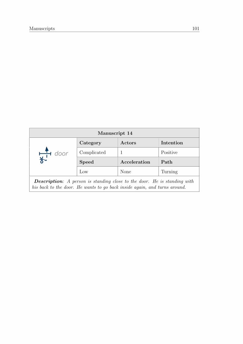
ii
“report” — 2011/6/20 — 15:25 — page 101 — #115 ii
ii
ii
Manuscripts 101
Manuscript 14
Category Actors Intention
Complicated 1 Positive
Speed Acceleration Path
door
Low None Turning
Description: A person is standing close to the door. He is standing withhis back to the door. He wants to go back inside again, and turns around.
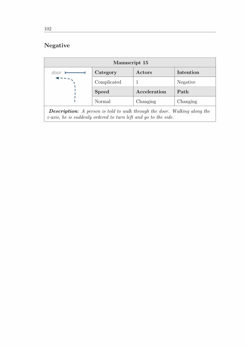
ii
“report” — 2011/6/20 — 15:25 — page 102 — #116 ii
ii
ii
102
Negative
Manuscript 15
Category Actors Intention
Complicated 1 Negative
Speed Acceleration Path
door
Normal Changing Changing
Description: A person is told to walk through the door. Walking along thez-axis, he is suddenly ordered to turn left and go to the side.
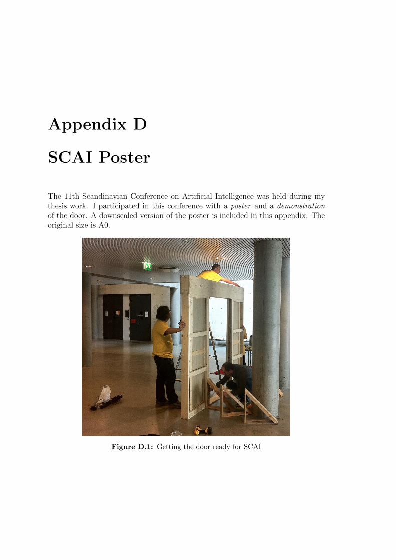
ii
“report” — 2011/6/20 — 15:25 — page 103 — #117 ii
ii
ii
Appendix D
SCAI Poster
The 11th Scandinavian Conference on Artificial Intelligence was held during mythesis work. I participated in this conference with a poster and a demonstrationof the door. A downscaled version of the poster is included in this appendix. Theoriginal size is A0.
Figure D.1: Getting the door ready for SCAI

ii
“report” — 2011/6/20 — 15:25 — page 104 — #118 ii
ii
ii
104
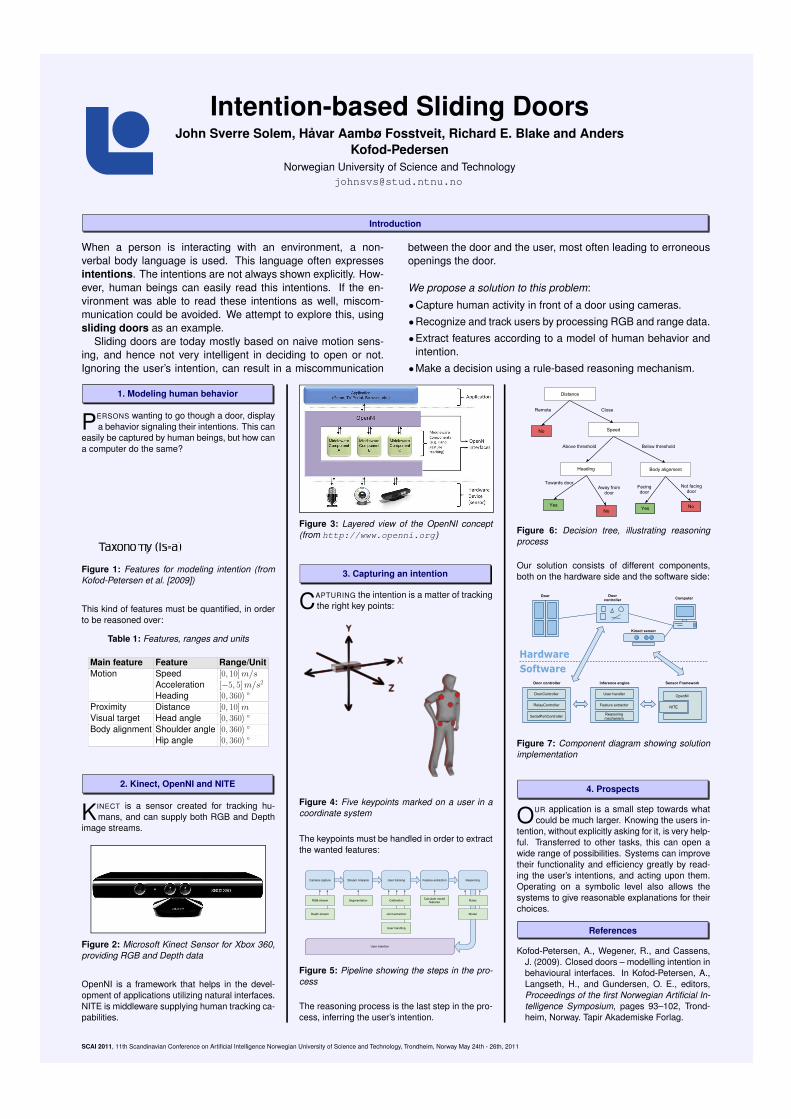
ii
“report” — 2011/6/20 — 15:25 — page 105 — #119 ii
ii
ii
Intention-based Sliding DoorsJohn Sverre Solem, Havar Aambø Fosstveit, Richard E. Blake and Anders
Kofod-PedersenNorwegian University of Science and Technology
Introduction
When a person is interacting with an environment, a non-verbal body language is used. This language often expressesintentions. The intentions are not always shown explicitly. How-ever, human beings can easily read this intentions. If the en-vironment was able to read these intentions as well, miscom-munication could be avoided. We attempt to explore this, usingsliding doors as an example.
Sliding doors are today mostly based on naive motion sens-ing, and hence not very intelligent in deciding to open or not.Ignoring the user’s intention, can result in a miscommunication
between the door and the user, most often leading to erroneousopenings the door.
We propose a solution to this problem:
•Capture human activity in front of a door using cameras.
•Recognize and track users by processing RGB and range data.
•Extract features according to a model of human behavior andintention.
•Make a decision using a rule-based reasoning mechanism.
1. Modeling human behavior
PERSONS wanting to go though a door, displaya behavior signaling their intentions. This can
easily be captured by human beings, but how cana computer do the same?
Figure 1: Features for modeling intention (fromKofod-Petersen et al. [2009])
This kind of features must be quantified, in orderto be reasoned over:
Table 1: Features, ranges and units
Main feature Feature Range/UnitMotion Speed [0, 10] m/s
Acceleration [−5, 5] m/s2
Heading [0, 360 Proximity Distance [0, 10] m
Visual target Head angle [0, 360 Body alignment Shoulder angle [0, 360
Hip angle [0, 360
2. Kinect, OpenNI and NITE
KINECT is a sensor created for tracking hu-mans, and can supply both RGB and Depth
image streams.
Figure 2: Microsoft Kinect Sensor for Xbox 360,providing RGB and Depth data
OpenNI is a framework that helps in the devel-opment of applications utilizing natural interfaces.NITE is middleware supplying human tracking ca-pabilities.
Figure 3: Layered view of the OpenNI concept(from http://www.openni.org)
3. Capturing an intention
CAPTURING the intention is a matter of trackingthe right key points:
Figure 4: Five keypoints marked on a user in acoordinate system
The keypoints must be handled in order to extractthe wanted features:
Figure 5: Pipeline showing the steps in the pro-cess
The reasoning process is the last step in the pro-cess, inferring the user’s intention.
Figure 6: Decision tree, illustrating reasoningprocess
Our solution consists of different components,both on the hardware side and the software side:
Figure 7: Component diagram showing solutionimplementation
4. Prospects
OUR application is a small step towards whatcould be much larger. Knowing the users in-
tention, without explicitly asking for it, is very help-ful. Transferred to other tasks, this can open awide range of possibilities. Systems can improvetheir functionality and efficiency greatly by read-ing the user’s intentions, and acting upon them.Operating on a symbolic level also allows thesystems to give reasonable explanations for theirchoices.
References
Kofod-Petersen, A., Wegener, R., and Cassens,J. (2009). Closed doors – modelling intention inbehavioural interfaces. In Kofod-Petersen, A.,Langseth, H., and Gundersen, O. E., editors,Proceedings of the first Norwegian Artificial In-telligence Symposium, pages 93–102, Trond-heim, Norway. Tapir Akademiske Forlag.
SCAI 2011, 11th Scandinavian Conference on Artificial Intelligence Norwegian University of Science and Technology, Trondheim, Norway May 24th - 26th, 2011