inter-ing 2005 - upm.ro · inter-ing 2005 ... (13crni30), the eb power for welding is (1…1,5) kw....
TRANSCRIPT
283
Inter-Ing 2005„INTERDISCIPLINARITY IN ENGINEERING”
SCIENTIFIC CONFERENCE WITH INTERNATIONAL PARTICIPATION,TG. MUREŞ – ROMÂNIA, 10 -11 November 2005.
USES OF THE ELECTRON BEAM FOR SPECIAL WELDINGS
DULĂU MIRCEA1 , DAVID LASZLO2 , OLTEAN STELIAN1 , ŞOAITA DUMITRU3
1 ”Petru Maior” University of Tg.Mureş, Electrical Department2 “Sapientia” University of Tg.Mures
3 ”Petru Maior” University of Tg.Mureş, ITM Department
Key words: electron beam welding, material processing, process control.
Abstract: Electron beams (EB) material processing is a non-conventional technique used inaeronautics, nuclear technologies, microelectronics, automobile industries, heavy construction, etc.Electron beam have many special properties which make them particularly well suited for use inmaterials handling through melting, welding, surface treatment, etc., taking into account that thismanufacturing is performed in vacuum. Some welding applications for fuel pulverizer, are presentedin this paper, based on experiments made on a high power electron beam processing system,developed by the authors and ICPE Bucharest at “Petru Maior” University of Tg.Mureş.
THEORETICAL ASPECTS OF ELECTRON BEAM
High energy Electron Beam (EB) is fundamentally a unique way of delivering large amountsof concentrated thermal energy to materials. The most common EB systems used inmanufacturing today are of the high vacuum design. The triode gun design consists of theCathode (filament and massive cathode), Electrode (Grid), Anode, Focusing and DeflectionCoils and High Voltage Cable. All of these components are housed in a vacuum vessel and isusually kept at high pressure. The magnetic focus coil located beneath the anode assemblyprovides the means for squeezing the beam into a tightly focused stream of energy or can beused to widely dispersed energy resource. The focus coil is circular in design and isconcentric with EB. An electrical current is passed through the coil which produces theresultant magnetic fluxes that act to converge the electron beam. The deflection coil isconfigured with four separately wound coils positioned at right angles to the column. The fourcoils are segmented as sets (x and y) each axis becomes a separate control allowing theenergising of each axis on command, thus steering the beam.The experimental EB equipment has four electrodes (Electron's Collectors) to capturereflected electrons from target surface, scanned and processed by EB. A self made specialinterface load the captured image and welding depth information in the RAM of an IBMcomputer for further processing. The interface system use a dedicate memory which aimedthe direct access from the deflection values to the deflection control system. The controlsystem also permits to the human operator access for visualising and modifying of someparameters.Other important part of an electron beam system is that which provides high vacuumenvironment, without which the beam cannot be generated.
THERMAL PROCESS IN ACTION ZONE OF EB
At electrons beam processing, in brake zone of electrons, depending on accelerating voltage,

284
current intensity, beam diameter, etc., is possible to obtain the following process: heating,melting formation, vaporisation, explosive ebullition and evacuation of substance.If the beam’s specific power is lower (concentration under 105 W/cm2), the material is heatedthrough conduction and the heated zone has a semisphere profile (Figure 1). At specific powervalues of 106 W/cm2, under action of vapor’s pressure, a cavity with vapors beginning toform, surrounded by melting material. For specific power values of (107-108) W/cm2, themelting and the vaporisation became explosive and is forming a crater, which can cross thematerial on the whole width. The mean theoretical and experimental researches regarding atelectrons beam action is achieve in specific power range of (105 – 107) W/cm2, (transientprocess and depth melting), this is the most interesting from point of view of the physics ofprocess. In this range, the electrons beam action is characterised through “cutter” meltingphenomena or depth fusion.
Fig.1 Heating with EB
The temperature repartition on channel height is not uniform, having a maximum (about5000 K) on the bottom of the channel and a minimum (about 2500-3000 K) on the top of thechannel. The result of an experimental determination show that is produce a transport ofmaterial from molten zone to solidifying zone, on horizontal and vertical directions.For solving of thermal conductivity problem, it must know the thermal source character andthermal balance of process. The experimental data from special literature shows that theheating losses at welding with electrons beam, are not bigger than (5-10) %, that is thermalbalance at (105-106) W/cm2 is the same like in electric arc heating. This lead to conclusion thatthe precision is enough for engineering calculations.Regarding to thermal source character, function of electrons beam depth in material, he issuperficial distributed normally or normally distributed at surface and in depth. For estimationof the thermal flux repartition can be used the normally source form, which present thecombination of two sources with simultaneous action: the distributed source on surface andthe distributed source in depth. At beam’s thermal power Q, the point source power q1 , withsurface action is Qkq ⋅=1 and the line source power q2 , with depth action is ( )q k Q2 1= − ⋅ ,where k is the energy distribution coefficient.The temperature in point M(x,y,z), in stationary, can be described with relation:
⎥⎥⎦
⎤
⎢⎢⎣
⎡
−++−
++++⋅
⋅⋅⋅+
⋅⋅⋅=
22
2221
)(
)(ln
42),,(
hzrhz
hzrhzh
qR
qzyxT
λπλπ(1)
where: R x y z= + +2 2 2 ; r x y= +2 2 ;h is the depth of melting hole;λ is the thermal conductivity;x, y, z are the coordinate of one point.
285
The ratio between this two sources, based on the results obtained by Rykalin, is:q1/q2 = (0.053…0.11). From thermal point of view the process is present like a timemodulation of the incident beam, which has, in the first period a line characteristic in depthdistributed, and in a second period, a point characteristic, situated in the molten which closethe hole, that is in the surface neighbourhood, at z = 0.
ELECTRON BEAM WELDING
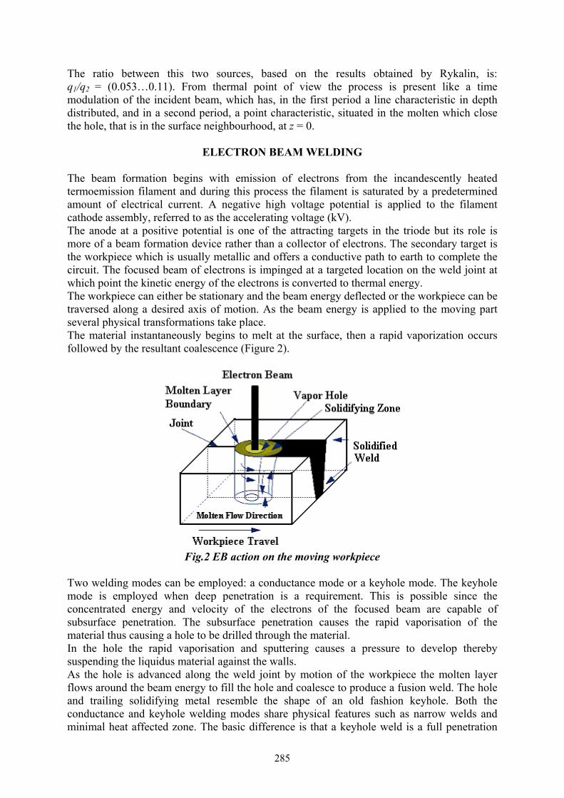
The beam formation begins with emission of electrons from the incandescently heatedtermoemission filament and during this process the filament is saturated by a predeterminedamount of electrical current. A negative high voltage potential is applied to the filamentcathode assembly, referred to as the accelerating voltage (kV).The anode at a positive potential is one of the attracting targets in the triode but its role ismore of a beam formation device rather than a collector of electrons. The secondary target isthe workpiece which is usually metallic and offers a conductive path to earth to complete thecircuit. The focused beam of electrons is impinged at a targeted location on the weld joint atwhich point the kinetic energy of the electrons is converted to thermal energy.The workpiece can either be stationary and the beam energy deflected or the workpiece can betraversed along a desired axis of motion. As the beam energy is applied to the moving partseveral physical transformations take place.The material instantaneously begins to melt at the surface, then a rapid vaporization occursfollowed by the resultant coalescence (Figure 2).
Fig.2 EB action on the moving workpiece
Two welding modes can be employed: a conductance mode or a keyhole mode. The keyholemode is employed when deep penetration is a requirement. This is possible since theconcentrated energy and velocity of the electrons of the focused beam are capable ofsubsurface penetration. The subsurface penetration causes the rapid vaporisation of thematerial thus causing a hole to be drilled through the material.In the hole the rapid vaporisation and sputtering causes a pressure to develop therebysuspending the liquidus material against the walls.As the hole is advanced along the weld joint by motion of the workpiece the molten layerflows around the beam energy to fill the hole and coalesce to produce a fusion weld. The holeand trailing solidifying metal resemble the shape of an old fashion keyhole. Both theconductance and keyhole welding modes share physical features such as narrow welds andminimal heat affected zone. The basic difference is that a keyhole weld is a full penetration
286
weld and a conductance weld usually carries a molten puddle and penetrates by virtue ofconduction of thermal energy.The processing current if, at an established accelerating voltage Ua, for a welding joint withconstant depth h and speed v, is determine from simplified relations of thermal model.Hashimoto and Matsuda propose using of the following relation, for different materials:
( ) ( )[ ] ⎥⎦
⎤⎢⎣
⎡⎟⎠⎞
⎜⎝⎛
⋅+
⋅⋅⋅⋅+⋅+−⋅
⋅⋅=
avrHTc
Urvhhvci ss
af 2
12
12,11273,,,, λρλρ (2)
where: Ts is the melting temperature;Hs - the melting heat;r – EB radius.
Arata and Tomie propose another simplified relation for Cr-Ni steel:
( ) 3,1
5,0310805,9,a
f Uvhhvi ⋅⋅⋅
= (3)
Welding conditions is mainly controlled by beam output power, welding speed and focalposition. The EB focus point is kept constant because the bias voltage is controlled.Nowadays, the EB equipments are very used for the precision welding: transmission gear,pistons, pulleys, compressors for car air-conditioners, turbo-chargers, pulverizers, etc.
EXPERIMENTAL RESULTS AND CONCLUSIONS
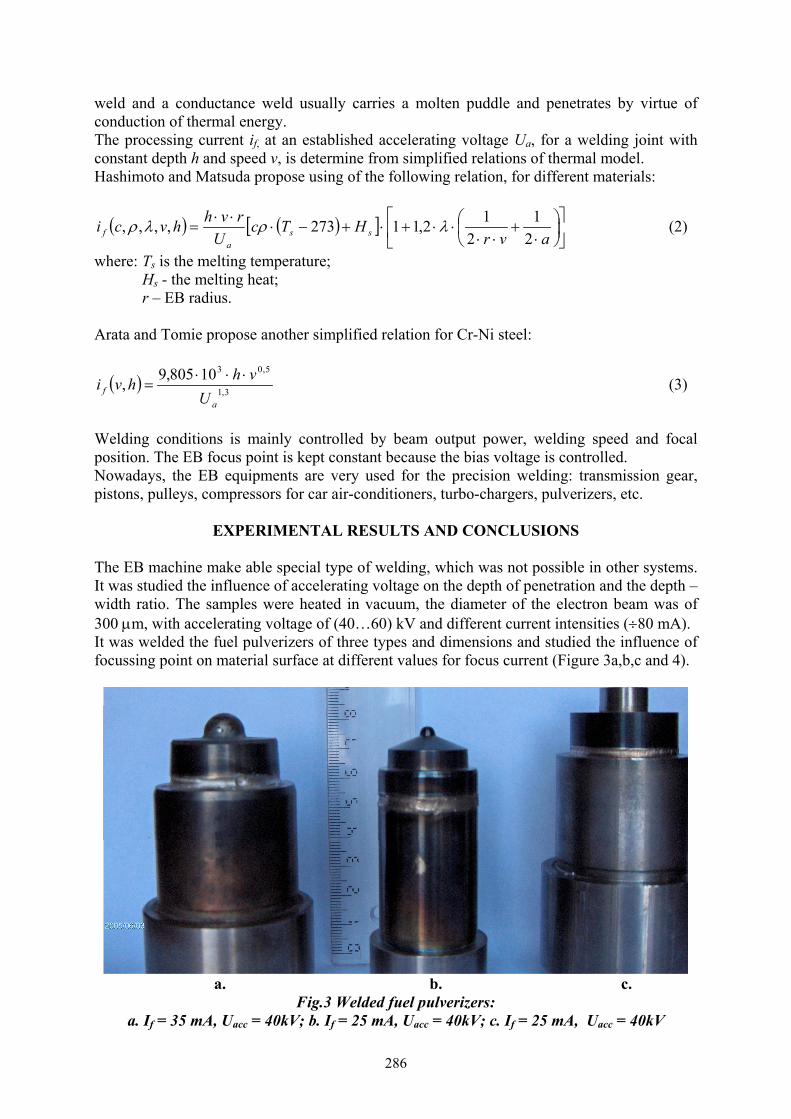
The EB machine make able special type of welding, which was not possible in other systems.It was studied the influence of accelerating voltage on the depth of penetration and the depth –width ratio. The samples were heated in vacuum, the diameter of the electron beam was of300 µm, with accelerating voltage of (40…60) kV and different current intensities (÷80 mA).It was welded the fuel pulverizers of three types and dimensions and studied the influence offocussing point on material surface at different values for focus current (Figure 3a,b,c and 4).
a. b. c.Fig.3 Welded fuel pulverizers:
a. If = 35 mA, Uacc = 40kV; b. If = 25 mA, Uacc = 40kV; c. If = 25 mA, Uacc = 40kV

287
Fig.4 Section of pulverizer from Fig.3b
Material 13CrNi30, STAS 791-88
C (0,09 - 0,16) %Si (0,17 - 0,37) %Mn (0,30 - 0,60) %Cr (0,60 - 0,90) %Ni (2,75 - 3,15) %
These weld are:• mark from Fig.3a – finished piece, welded with 35 mA, 40kV, 2mm/sec, preheating,
single pass welding, EB overfocussed.• mark from Fig.3b – finished piece, welded with 25 mA, 40kV, 2mm/sec, preheating, three
pass welding, EB overfocussed.• mark from Fig.3c – unfinished piece, welded with 25 mA, 40kV, 2mm/sec, preheating,
single pass welding, EB overfocussed.The first weld was compromised because of explosions inside the channel. This problem wassolved through another welding, but, in this case, the surface of joint is unhomogeneous(Figure 5). This lead to conclusion that, for a very good quality of welding is need apreheating process of joint at 0,5 kW and overfocussed EB. In this case the diameter of EB is(1…2) mm, on the material surface.
Fig.5 Welding with explosions
The welding parameters was calculated based on relation (3), started with imposed depthpenetration h=(1,5…2,5) mm. From accelerating voltage of 40 kV and based on materialproperties (13CrNi30), the EB power for welding is (1…1,5) kW.The EB, welding in a vacuum, guaranties stable welding quality and this is easily achievedwith a long beam focusing depth and prevention oxidation. Causing the EB to oscillate isreducing welding defects: cracks, blow hole, etc.The main advantages of using EB technologies are:• the possibility to generate of cuasistationary energy source for any surface, for any power
density distribution and for any time dependence;

288
• high efficiency of beam power conversion in thermal power (η>0.75 for Fe alloy).Based on previous advantages, the using of EB equipment for welding technologies isindicated in (1…120) kW range at high productivity and flexibility.The EB gun with work chamber, from “Petru Maior” University of Tg.Mureş, has thefollowing main characteristics:• Triode type CTW 5/60; Ua=60kV; Pu=5kW; If = 85 mA;• Inside dimensions of vacuum chamber (650x650x500) mm.
Acknowledgement: The experimental results of this paper was supported by an EB materialprocessing equipment developed by "Petru Maior" University of Tg. Mureş and ElectricalResearch Institute ICPE Bucharest.
REFERENCES
[1] Bakish, R., Introduction to Electron Beam Technology. John Wiley & Sons, Inc., NewYork, 1985.
[2] Arata, Y., Tomie, M., Untersuchung einer sehr leistungsstarken ElektronensrtahlWarmequelle und ihre Anwendung zum Schweissen. IIW-Dokument IV-309, 1981.
[3] Hashimoto, T., Matsuda, F. Penetration of weld bead in electron beam welding. Trans.Nat. Res. Inst. for Metals (1065).
[4] David, L., Contribuţii la optimizarea procesului de prelucrare cu fascicul de electroniacceleraţi. Teza de doctorat, Universitatea Transilvania Braşov, 1997.
[5] Dulău M., Controlul procesării cu fascicul de electroni. Modelare. Simulare. Aplicaţii,Editura Universităţii “Petru Maior” Tg.Mureş, 2005.
[6] David L., Şoaita D., Dulău M., Applications of high power electron beam welding,Conferinţa internaţională de inginerie integrată, C2I 2002, Timişoara, pag. 87-88, EdituraPolitehnica, 2002.
[7] Dulău M., Morar Al., David L., Applications of high power electron beam processing,Revista Acta Electrotehnica, Academy of Technical Sciences of Romania, TechnicalUniversity of Cluj-Napoca, Romania, Volume 45, Number 4, pp.469 – 474, MediamiraScience Publisher, Cluj-Napoca, 2004.