interactive structural analysis
TRANSCRIPT

Interactive Structural Analysis
Odysseas Georgiou University of Bath
London, UK [email protected]
Abstract This paper re-approaches structural engineering through an interactive perspective by introducing a series of tools that concatenate parametric design with structural analysis, thus achieving interoperability between form and its structural performance. Parametric Design is linked to Structural Analysis using computer programming to establish a common interactive framework that leads to performance based designs that respond to structural constrains and conditions in an interactive manner. A series of examples illustrate the synergy between form and structure by interactively modelling, analysing and visualizing its response.
1. Introduction The digital age has introduced new ways of approaching architectural design. Modern digital tools (CAD), allow geometric freedom that in turn enables designers to overcome traditional design boundaries and transform almost any form into a constructible building. The development of complex forms in architecture led to the transition from the traditional, static design approach, to a “dynamic” process [1], [3] and forced computers to become “design generators” [2] and CAD tools to move away from their conventional drafting role. The development of generative design methods, or commonly parametric design, enables the designer to describe mathematically complex forms and explore new ones while understanding their conceptual functions.

Since building forms are becoming more complex, the engineering input is becoming essential from the concept stages and the role of the engineer in a design collaboration is enhanced. Despite that, there seems to be a gap between the ways the two disciplines interact. While a concept form can be shaped, understood and altered quickly by the architect, an engineer cannot assess the data given in analogous speed. For a given free form shape, developed with ease inside a Parametric CAD environment, extensive analysis needs to take place on the engineering side for it to be structurally assessed. Most of the times, the full behaviour is not fully understood due to the time chasm between modelling, analysis and assessment and just static performance feedback is returned for the shape analysed. Structural constraints, such as performance of structural members or materials and boundary conditions for example, are not controlled equally by Structural Analysis software as opposed to the way geometrical constraints are treated by Parametric Design software. Conceptual structural engineering of complex shapes cannot follow the rapid and constantly shifting architectural object that it is summoned to support. The digital design process needs to be enhanced and be able to stimulate solutions which respond to structural performance and conditions. There are a few examples that implement the notion of structural performance models applied on specific projects as Phaeno Science Center [4] and Lansdowne Road Stadium [5]. A more global example of performance based design of roof trusses can be found in Ref [2]. Moreover, there are cases that implement other types of data as lighting or thermal information to generate performance based models [6]. This paper illustrates a synergy between the architectural shape and its structural performance through an interactive link between a Parametric Design tool, Grasshopper 3d [7], and a Structural Analysis Software, Autodesk’s Robot Structural Analysis [8] and demonstrates how performance can be incorporated into the design process in order to firstly generate an analytical model of the given shape and secondly iterate between a set of efficient structural solutions that apply to that shape. 2. Methodology To illustrate an overview of a performance based structural design, a series of definitions were assembled by linking together McNeal’s Grasshopper 3D and Autodesk’s Robot Structural Analysis [19] using C# programming language.
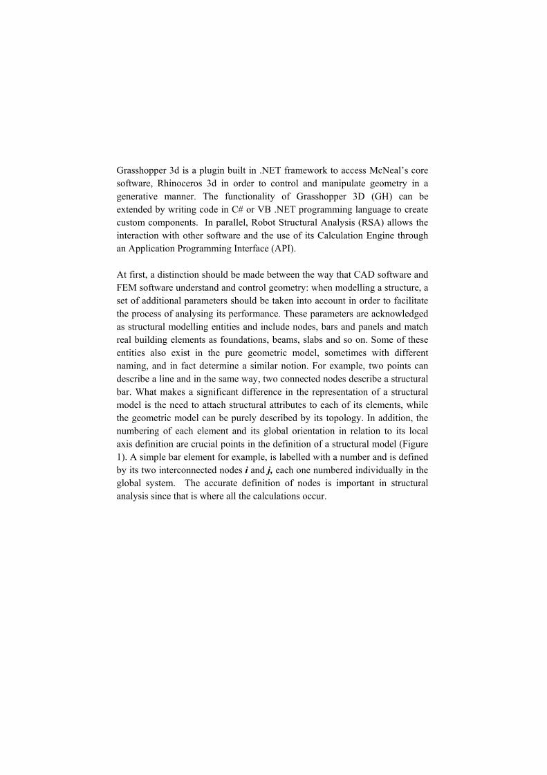
Grasshopper 3d is a plugin built in .NET framework to access McNeal’s core software, Rhinoceros 3d in order to control and manipulate geometry in a generative manner. The functionality of Grasshopper 3D (GH) can be extended by writing code in C# or VB .NET programming language to create custom components. In parallel, Robot Structural Analysis (RSA) allows the interaction with other software and the use of its Calculation Engine through an Application Programming Interface (API). At first, a distinction should be made between the way that CAD software and FEM software understand and control geometry: when modelling a structure, a set of additional parameters should be taken into account in order to facilitate the process of analysing its performance. These parameters are acknowledged as structural modelling entities and include nodes, bars and panels and match real building elements as foundations, beams, slabs and so on. Some of these entities also exist in the pure geometric model, sometimes with different naming, and in fact determine a similar notion. For example, two points can describe a line and in the same way, two connected nodes describe a structural bar. What makes a significant difference in the representation of a structural model is the need to attach structural attributes to each of its elements, while the geometric model can be purely described by its topology. In addition, the numbering of each element and its global orientation in relation to its local axis definition are crucial points in the definition of a structural model (Figure 1). A simple bar element for example, is labelled with a number and is defined by its two interconnected nodes i and j, each one numbered individually in the global system. The accurate definition of nodes is important in structural analysis since that is where all the calculations occur.

Fig 1
Thus, eaccordinstructurand are define aa geomcontrollcalled Ra set ofperformmatch thactual sRobotNand z RobotNfor crea 2.1. Ex
The fodiamenschange
1- Local Coor
each node ngly to be reral bar, the lin
used to defia structural b
metric line toled using an Robot Objectf data, defin
med which arhe operationssoftware envi
Node interfaceglobal coo
NodeServer inating a new n
ample 1: Pa
ollowing exasional definiof a paramet
rdinate systemStructural A
that definesead by RSA.ne’s start andine two new bar since thero a bar. Eaappropriate i
t Model [9]. Aned as attribure called funs that a user ironment. Ae, which amoordinates. nterface, whiode.
arametric Tr
ample showition of a Trter inside Gra
m and sign ConAnalysis v.18 U
s geometry . For exampld end point cnodes for R
re does not each structurainterface, whAn interface utes or memnctions. Thefollows to m
A node for exong others in Each nodich for exam
russ
ws the proceruss where iasshopper 3d
nvention, ImagUser’s Manual
in GH nele in order tocoordinates a
RSA. Those nexist an implial member inhich is includis a software
mbers, and opese interface
model and anaxample can b
ncludes three de can be mple includes
edure followits performand’s visual env
ge courtesy of l
eds to be o translate a
are extracted nodes are theicit way of trn RSA is dded in the APe structure coperations thas and their alyse a structbe representereal numbermanaged u
s the Create
wed to modnce respondsvironment.
f Robot
modified a line to a
from GH en used to ranslating efined or
PI library, omprising at can be functions
ture in the ed by the rs for x, y using the e function
del a 2-s to each
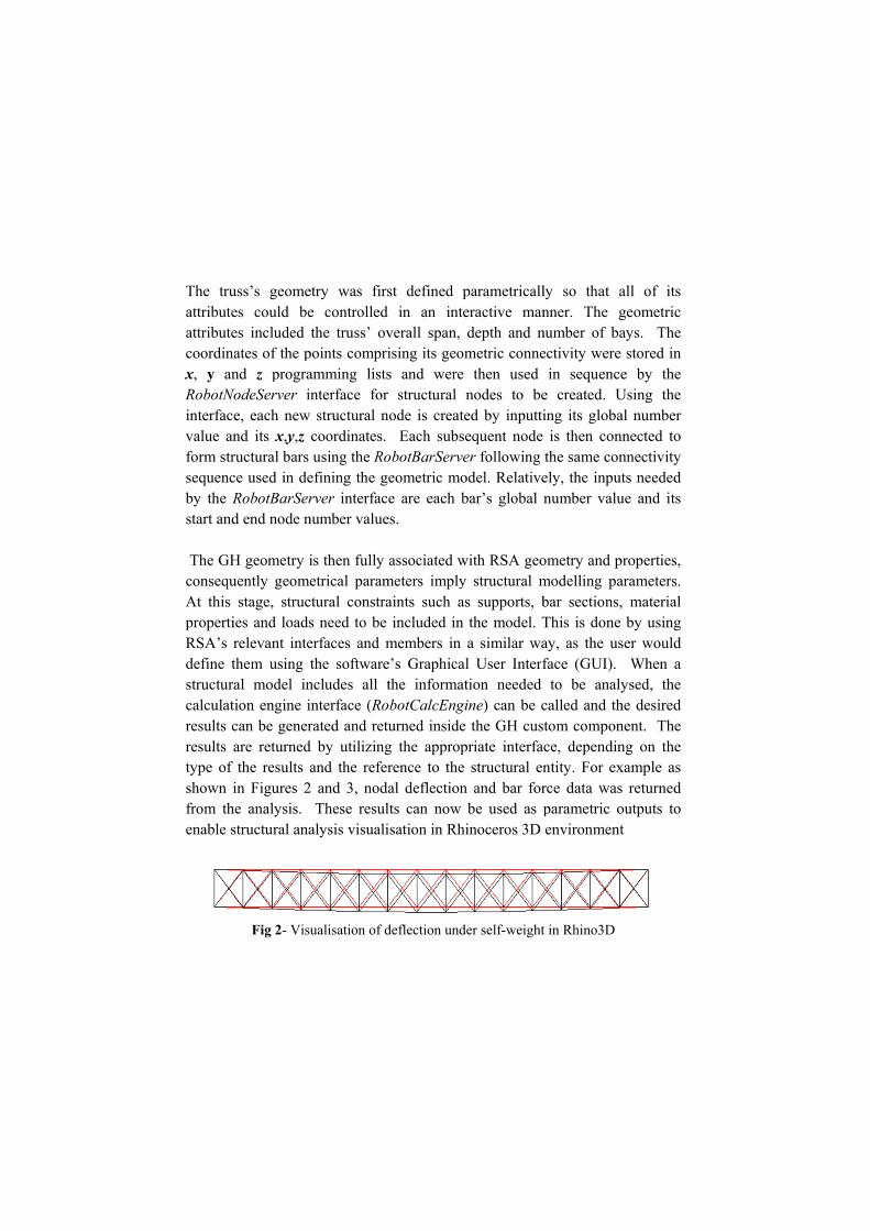
The truattributeattributecoordinx, y anRobotNinterfacvalue anform strsequencby the Rstart and The GHconsequAt this propertiRSA’s define tstructurcalculatresults cresults type of shown ifrom thenable s
uss’s geomees could bees included
nates of the pnd z progra
NodeServer ine, each new nd its x,y,z ructural bars ce used in deRobotBarSerd end node n
H geometry iuently geome
stage, strucies and loadsrelevant intethem using tral model intion engine ican be generare returned
f the results ain Figures 2
he analysis. structural ana
Fig 2- Visu
etry was firse controlled the truss’ ov
points compriamming listsnterface for structural n
coordinates. using the Ro
efining the grver interfac
number value
is then fully etrical param
ctural constras need to be erfaces and mthe software
ncludes all tnterface (Rorated and retu
d by utilizingand the refer
2 and 3, nodaThese resul
alysis visuali
ualisation of d
st defined pin an inte
verall span, ising its geoms and were
structural nnode is create
Each subseobotBarServeeometric moe are each b
es.
associated wmeters implyaints such asincluded in
members in e’s Graphicalthe informat
obotCalcEngiurned inside g the approprence to the al deflectionlts can now isation in Rhi
deflection und
parametricalleractive mandepth and nmetric conne
then used nodes to beed by inputtiequent node er following odel. Relativebar’s global n
with RSA geoy structural ms supports, bthe model. Ta similar wal User Interftion needed ine) can be cthe GH cus
priate interfacstructural en
n and bar forbe used as pinoceros 3D
er self-weight
ly so that anner. The g
number of baectivity were
in sequencee created. Uing its globais then con
the same conely, the inputnumber valu
ometry and pmodelling pabar sections,This is done ay, as the usface (GUI).
to be analycalled and thtom componce, dependinntity. For exrce data wasparametric oenvironment
t in Rhino3D
all of its geometric ays. The stored in
e by the Using the al number nnected to nnectivity ts needed
ue and its
properties, arameters. , material by using
ser would When a ysed, the
he desired nent. The ng on the xample as s returned outputs to t

Fig 3- V
Furthermmodel, additionRhinocetruss’ toIn a simnumeric
Fig 4
A wide custom given btruss tyselectio
Visualisation o
more, as a mparametric c
n to the algoeros‘s enviroop chord whmilar mannercal slider in r
4 - Any arbitraposition can
range of parcomponent
by selecting ypes (Brownn from RSA
of the distribu
means to increcontrol to aorithm enabonment to beich can be cr, the truss’ respect to the
ary load case cbe changed us
rameters is pofor the trusmultiple loa
n truss, Pratsteel section
ution of forces Rhino3D
ease the functdditional strles any line
e used to appontrolled in support poin
e original edg
curve can be dsing a numeric
ossible to be s and in the
ad cases or ltt truss and n library and
in each eleme
tionality of thructural variae of load or ply a distribureal time by
nts can be mge supports (s
drawn in Rhinocal slider in G
added and coe current conload case co
Vierendeel truss length (
ent under self-
he performanables was ad
any curve uted load ca
y curve contrmoved by usisee Figure 4)
o 3D and the s
Grasshopper 3D
ontrolled witntext, such combinations,
truss), sect(see Figure 5
weight in
nce based dded. An drawn in
ase on the rol points. ing a GH ).
support D
thin GH’s control is different
tion type 5).

2.2. Ex
As the design mmodel agrillageGrasshostructurrespond
Fig 5 - Defi
ample 2: 3D
previous examodel, it did among the tw is linked to
opper 3d. Byre where itding to the ch
ining the truss
D Grillage
ample illustrnot show th
wo disciplineo a free-form
y this means,ts performahange of geom
Fig 6
’ parameters in
rated the gene possibility es. In this exm surface th, any compleance attributmetry.
6 - Free-form s
n Grasshoppe
neration of a for a commo
xample a 3-dhat is modelex architecturtes are vis
surface
r’s sketchpad.
parametric only shared gdimensional lled parametral skin can sualised inte
.
structural geometric structural
trically in acquire a eractively

In this cselectiosoftwareaccordin
The edgspacingthe surfthe grillto genenodal losection a genercomponStructurtasks (avisualisthe analnodes adistribu
case the paran and is thene. These rng to the load
ges of the g bays genera
face accordinlage. The seterate the 3-doading to be types and marative mannenents. It is thral Analysis as this toolse the currenlytical modelnd the constr
ution along th
ametric surfan transformeregions alsod-cases set b
Fig 7
generated regating structurng to a contrt of nodes aredimensional g
applied to taterial propeer by the
he user’s chosoftware, in
s’ capabilitient results in l in RSA inclrain conditio
he bars of the
ace is split ined to structuro form the y the user (F
- Division in
gions are subral nodes. Throllable parame then connegrillage. Thethe structuralerties are also
user, either ice to compun order to pes are limiteGrasshopperluding the pons (Figure 8)
e grillage in G
nto regions acral data to beloading stri
Figure 7).
regions
bdivided intohe nodes aremeter which ected with stre surface loal nodes. The o parameters
using numute the analyperform mored to concepr. The followoint loads ass) and the visuGrasshopper’
ccording to te read by theips of the
o the desiredthen offset ndefines the
ructural bars ading is tran constrain cothat can be derical slider
ytical model ire rigorous aptual analysiwing images signed on to ualisation of ’s envorment
the user’s e analysis structure,
d grillage normal to height of in space,
nslated to onditions, defined in rs or text inside the analytical is), or to illustrate
structural the stress
t.
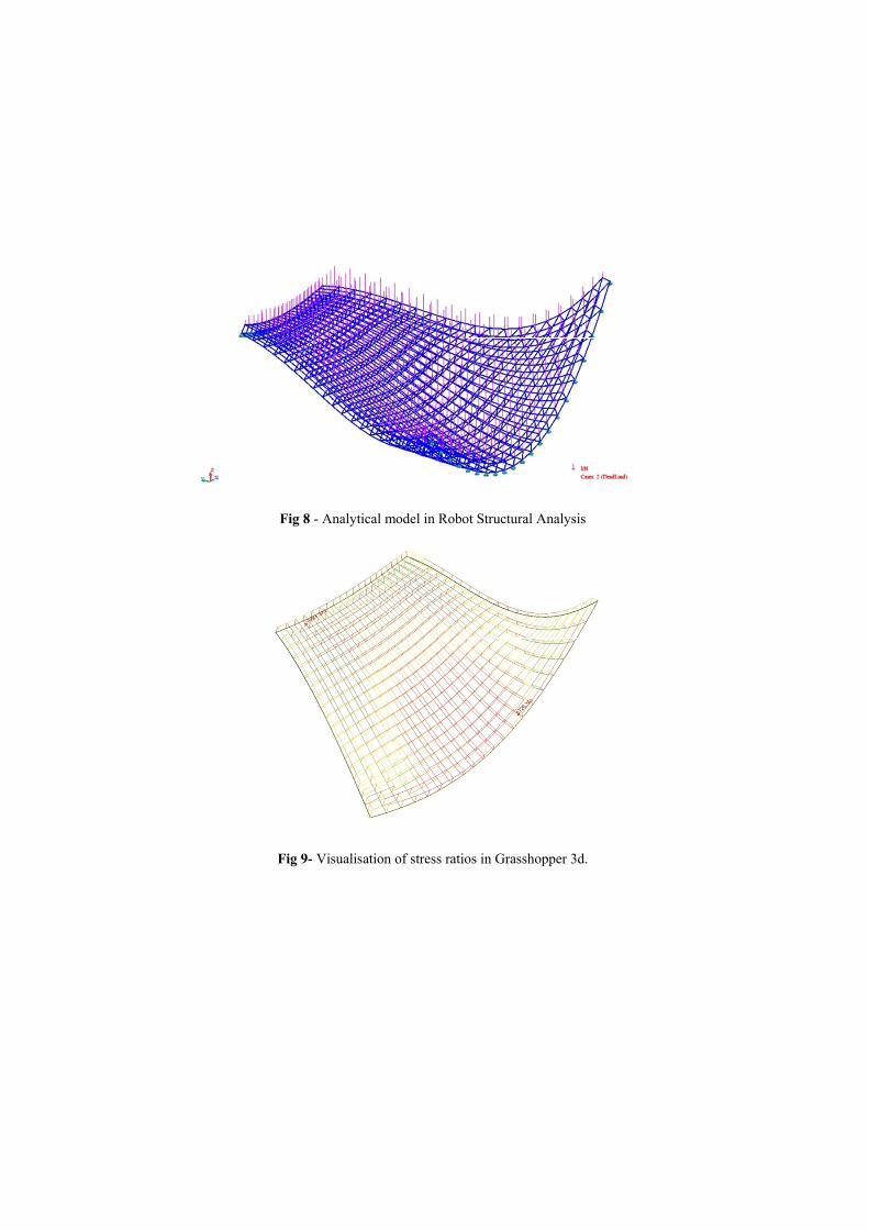
Fig 8
Fig 9-
- Analytical m
- Visualisation
model in Robo
n of stress ratio
ot Structural A
os in Grasshop
Analysis
pper 3d.
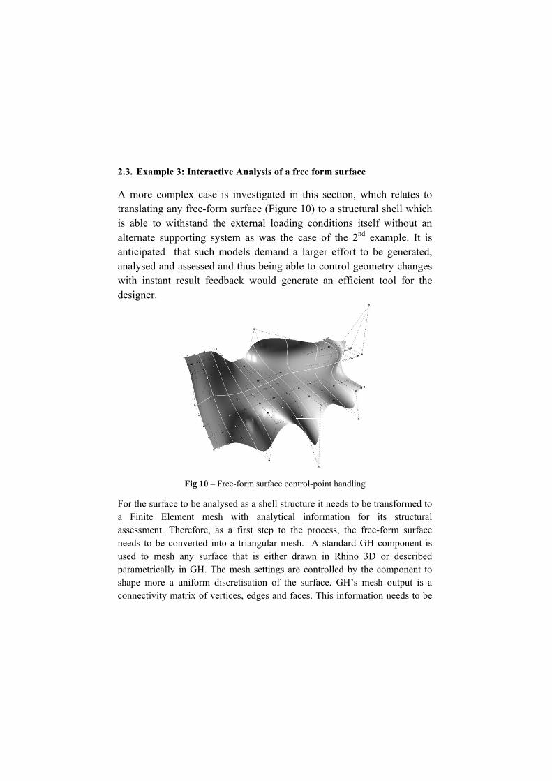
2.3. Ex
A moretranslatis able alternatanticipaanalysewith indesigne
For the a Finitassessmneeds toused toparametshape mconnect
ample 3: Int
e complex ting any fre to withstante supportinated that sed and assesnstant resulter.
Fig
surface to bete Element
ment. Therefoo be convert
o mesh any trically in Gmore a unifotivity matrix
teractive An
case is invee-form surfnd the exteng system asuch modelsssed and thut feedback
10 – Free-for
e analysed asmesh with
ore, as a firted into a trisurface thatH. The mesh
orm discretisof vertices,
nalysis of a f
vestigated inface (Figureernal loadinas was the s demand aus being abwould gen
rm surface con
s a shell struch analytical st step to thiangular mest is either dh settings arsation of theedges and fa
free form sur
n this sectioe 10) to a strng condition
case of thea larger effole to contro
nerate an ef
ntrol-point han
cture it needsinformation
he process, tsh. A standadrawn in Rhe controlled
e surface. GHaces. This inf
rface
on, which rructural shens itself wie 2nd examport to be geol geometry fficient tool
ndling
s to be transfn for its the free-formard GH comhino 3D or
by the compH’s mesh ouformation ne
relates to ell which ithout an ple. It is enerated, changes
l for the
formed to structural
m surface mponent is
described ponent to utput is a eeds to be

decomposed in elements that can be read by the structural analysis component. The mesh vertices are translated in a list of points in 3D space, which are then translated in structural nodes inside the analysis component. Up to this point, no relation between the nodes exists only an unreferenced point cloud is drawn in RSA. The connectivity of each face is then used to create arrays of nodes by selecting the three points that comprise each face out of the list. Finite elements can then be created by utilizing the arrays created using the FiniteElems interface in RSA. Structural properties need to then be applied, which are treated in a way that allows them to be controlled parametrically by the user through the GH graphical interface. The properties that are essential for the analytical process are: the type of the elements, which are set to planar 3-node elements with constant thickness, the material that either is pre-set from RSA’s library or can manually be defined by its properties and the element’s thickness. The model’s supports are initialised to the edges by selecting all the nodes that lie on the mesh’s outline. The border of the mesh is isolated by utilizing the topological information of the mesh by accessing Rhino.NET SDK [10]. A routine is formed to run through all the edges that form the mesh’s topology and select the ones that are “naked”, which means that they are only connected to one face. The vertices that belong to those edges are output to the analysis component and are selected as nodes that contain support information. The option of adding supports on points that did not necessarily coincided with the mesh vertices was also implemented by subdividing the mesh around the area to be supported. The topological information is lost when the mesh is translated to FE for the structural modelling and therefore the index of each support vertex needs to be found from the list of nodes that are already drawn in the model. After the structural information database is complete, the calculation interface can be called and results can be output for each finite element. For the purpose of graphical representation of the FEA results, each face was translated into a triangulated surface while keeping the topological information of the mesh. Consequently, the analysis results are mapped with each surface facet and their values can be tagged accordingly or coloured using a GH

Gradienimpact surface
Fig
3. ConAn Intethroughsoftwaredesign, problemdesign analyse a real-tisolutiondesign complex
nt componenof change oin Rhino’s V
g 11 - Graphic
nclusions gration betw
h the synerge. This coma function w
ms. As mentioare readily and manipul
ime manner. ns. The invois essential
x forms. Thi
nt. This resuon the geomViewport (see
cal representat
ween the formgy between mbination enwhich currentoned in the iavailable to
late models q This proces
olvement of in modern
s offers a qu
ults to the metry or the c
e Figure 11).
tion of surface
m and its struParametric
nabled an intly is sparingintroduction, o architects. quickly, whilss often leada structuralarchitecture
ick insight to
interactive rconstraints o
e stress ratios i
uctural perforDesign and
nteractive apgly applied fo tools that aiThese allow
le being ableds to architecl engineer ine and partico the structur
representatioof the initial
in Grasshoppe
rmance was id Structural pproach to or solving enid fast and asw them to
e to visualise cturally elegan the early cularly in reral performan
on of the l NURBS
er 3D
illustrated Analysis
structural ngineering ssociative generate, results in
ant design stages of egards to nce of the
form and aids increasing efficiency in the whole design process. However, without the use of compatible tools, an engineer not only fails to support architectural design but also moves away from efficient solutions. The generation of structurally responsive parametric models enables the iteration between ranges of efficient solutions while being able to react to each change of the architectural geometry rapidly. This paper demonstrated the application of the method through three examples: a simply supported truss, a 3D grillage and a shell structure of a free-form surface. The possibility for all three models to adapt to multiple variations of shape and the continuous user interaction was persistent in all cases. This also illustrates the methods’ applicability to a range of architectural and structural engineering problems.
3.1. Future Work
Future extensions to the performance based parametric components include:
- The initialisation of Robot Structural Analysis member design engine would allow designing and checking structural members while ensuring their structural efficiency.
- The implementation of improved subdivision algorithms for the generation of mesh emitters around the support points to improve the distribution of stresses related to the interactive analysis of a shell structures.
- Including a greater range of structural elements in a single model would allow the generation of performance models which contain largest amounts of assessable information which would enable a more holistic approach to the problem.

References
1. Aish, R.,Woodbury,R., Multi-Level Interaction in Parametric Design. Bentley Systems Incorporated.
2. Kristina Shea, Robert Aish & Marina Gourtovaia. (2005).Towards integrated performance-driven generative design tools. Automation in Construction. March 2005, 14(2).pp. 253-264.
3. Papalexopoulos D., Stavridou A., Papadopoulos D., 2007, Conceptual determination of parametric attributes of architectural construction elements and materials (free translation) . National Technical University of Athens, Athens.
4. Littlefield D., ed., 2008. Space Craft-Developments in Architectural Computing- Geometry form and complexity. London: RIBA Publishing.
5. Shepherd, P., Hudson, R., Parametric Definition of the Lansdowne Road Stadium. International Association of Shell and Spatial Structures. 2007, Venice, Italy.
6. Caldas, L., GENE_ARCH: An Evolution-Based Generative Design System for Sustainable Architecture. Intelligent Computing in Engineering and Architecture. Lecture Notes in Computer Science, 2006, Volume 4200/2006, 109-11.
7. Grasshopper- Generative modelling for Rhino [online]. Available from : http://www.grasshopper3D.com/ [Accessed 22 Dec 2010].
8. Autodesk- Autodesk Robot Structural Analysis Professional[online]. Availablefrom:http://usa.autodesk.com/adsk/servlet/pc/index?siteID=123 112&id=11818169 [Accessed on 20 Dec 2010].
9. Autodesk Inc., 2009. Autodesk Robot Structural Analysis 2010 – Robot Object Model.
10. Developer: dotnetplugins- McNeel Wiki [online] Availble from: http://wiki.mcneel.com/developer/dotnetplugins [Accessed 20 July 2010].