interface photos 1 2 - rci, inc. - rci, inc. is an...
TRANSCRIPT
INTRODUCTION AND EXECUTIVE SUMMARY
This case study supplements a prior report (ldquoSolar-Driven Waves of Water Vapor Within Exterior Wall Cavitiesrdquo) published in the July 2014 issue of Interface That article described our teamrsquos large-scale use of humiditytemperature loggers1 to measure ambient moisture load data within occupiable apartments and exterior wall cavities at mul-tiple two-story buildings at a residential complex near San Francisco Specifically this report analyzes the daily spikes of water vapor intru-sion into these walls and buildings that occurred when two rain-wetted claddings (traditional three-coat stucco and fiber-cement lap siding) were heated by the sun
As previously reported during our 162-day testing period2 these dataloggers recorded (every 10 minutes 144 times per day)3 ambient relative humidity (RH) and temperature conditions at 24 ground-floor apartments Concurrent measurements from several exterior loggers supplemented these interior data In total more than 48 million temperature and RH
data points were collected from these var-ious sensors
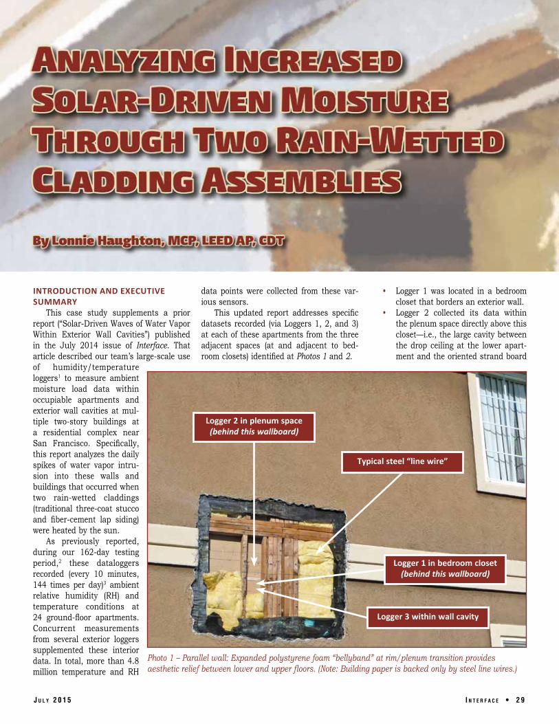
This updated report addresses specific datasets recorded (via Loggers 1 2 and 3) at each of these apartments from the three adjacent spaces (at and adjacent to bed-room closets) identified at Photos 1 and 2
bull Logger 1 was located in a bedroom closet that borders an exterior wall
bull Logger 2 collected its data within the plenum space directly above this closetmdashie the large cavity between the drop ceiling at the lower apart-ment and the oriented strand board
Logger 2 in plenum space (behind this wallboard)
Logger 1 in bedroom closet (behind this wallboard)
Typical steel ldquoline wirerdquo
Logger 3 within wall cavity
Photo 1 ndash Parallel wall Expanded polystyrene foam ldquobellybandrdquo at rimplenum transition provides aesthetic relief between lower and upper floors (Note Building paper is backed only by steel line wires)
J u l y 2 0 1 5 I n t e r f a c e bull 2 9
(OSB) subfloorabove
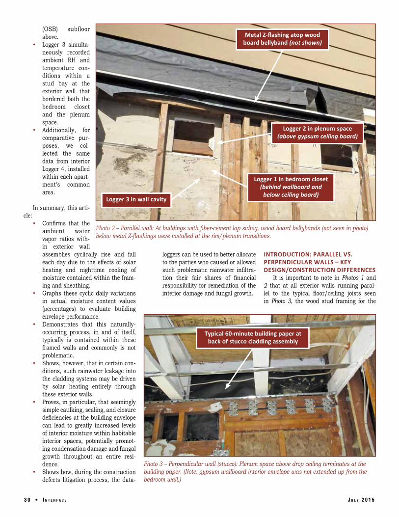
bull Logger 3 simulta-neously recordedambient RH andtemperature con-ditions within a stud bay at theexterior wall that bordered both the bedroom closet and the plenumspace
bull Additionally forcomparative pur-poses we col-lected the same data from interior Logger 4 installed within each apart-mentrsquos common area
In summary this arti-cle
Metal Z-flashing atop wood board bellyband (not shown)
Logger 2 in plenum space (above gypsum ceiling board)
Logger 1 in bedroom closet (behind wallboard and
below ceiling board) Logger 3 in wall cavity
bull Confirms that the Photo 2 ndash Parallel wall At buildings with fiber-cement lap siding wood board bellybands (not seen in photo) ambient water below metal Z-flashings were installed at the rimplenum transitions vapor ratios with-
in exterior wall assemblies cyclically rise and fall loggers can be used to better allocate INTRODUCTION PARALLEL VS each day due to the effects of solar to the parties who caused or allowed PERPENDICULAR WALLS ndash KEY heating and nighttime cooling of such problematic rainwater infiltra- DESIGNCONSTRUCTION DIFFERENCES moisture contained within the fram- tion their fair shares of financial It is important to note in Photos 1 and ing and sheathing responsibility for remediation of the 2 that at all exterior walls running paral-
bull Graphs these cyclic daily variations interior damage and fungal growth lel to the typical floorceiling joists seen in actual moisture content values in Photo 3 the wood stud framing for the (percentages) to evaluate building envelope performance
bull Demonstrates that this naturally-occurring process in and of itself typically is contained within these framed walls and commonly is not problematic
bull Shows however that in certain con-ditions such rainwater leakage into the cladding systems may be driven by solar heating entirely through these exterior walls
bull Proves in particular that seemingly simple caulking sealing and closure deficiencies at the building envelope can lead to greatly increased levels of interior moisture within habitable interior spaces potentially promot-ing condensation damage and fungal growth throughout an entire resi-dence
bull Shows how during the construction defects litigation process the data-
Typical 60-minute building paper at back of stucco cladding assembly
Photo 3 ndash Perpendicular wall (stucco) Plenum space above drop ceiling terminates at the building paper (Note gypsum wallboard interior envelope was not extended up from the bedroom wall)
3 0 bull I n t e r f a c e J u l y 2 0 1 5
No interior envelope was provided at rimplenum transition (typical)
lower apartment terminates at tripled plates at the top of the plenum cavity (as opposed to conventional platform framing where the lower studs would terminate at doubled plates at the bottom of the plenum space)
As reviewed below this atypical design allowed us to directly compare migration rates of solar-heated mois-ture from the same stud bay (Logger 3) into two distinct spaces the conditioned bed-room closet (Logger 1) and the indirectly conditioned plenum space above the drop ceiling (Logger 2)
In contrast the wood-blocked construction of the opposing perpendicular walls (per Photo 3) is typical for Western platform framing however we can see in Photos 3 and 4 that the gypsum wall-Photo 4 ndash Perpendicular wall (siding) Plenum space above drop ceiling terminates at inside face of the board interior envelope provid-exterior gypsum sheathing behind the wood board bellyband and the fiber-cement siding ed at the lower unit was not extended up into the plenum
space For example the 60-minute building paper behind the three-coat stucco is visible in Photo 3
Typical for mass-produced housing projects here in California certain portions of the stucco cladding were installed over OSB shear panels (Photos 5 and 6) but for most of the stud bays the building paper serving the stucco was backed only by steel ldquoline wiresrdquo per Photo 1
A key goal of our testing program was to evaluate potential sources of the excess water vapor and related condensation damage (eg Photos 6 and 7) observed at the rimplenum transitions4
INTRODUCTION ndash THE HUMIDITY RATIO Concurrent measurements of temperature and RH can be con-
verted into the ldquohumidity ratiordquomdashthe ratio or percentage of the weight of ambient water vapor molecules per pound of dry air5 The software for our loggers was programmed to calculate a grains-per-pound (GPP) ratio6
In a manner comparable to a construction professionalrsquos forensic use of pin-style moisture meters to take multiple ldquowetrdquo vs ldquoless wetrdquo vs ldquodryrdquo readings (ie percentages) at wood studs and sheathing throughout a project our loggers produced 24 million humidity ratio (ldquoambient moisture contentrdquo) readings over the 162-day testing period
Photo 5 ndash Perpendicular wall Typical EPS foam bellyband at rim plenum transition provides aesthetic relief between lower and upper floors (At building corners stucco is installed to OSB shear panels)
J u l y 2 0 1 5 I n t e r f a c e bull 3 1
Photo 6 ndash Perpendicular wall (stucco) No interior envelope was provided at the rimplenum transition
We then used Microsoft Excel spread-sheets to process and graph selected portions of these data to evalu-ate questions of interest For example consider Graph 1 which displays ambient moisture con-tent readings measured concurrently (144 times per day starting at 1200 am) over a 17-day peri-od at Logger 3 (within an exterior wall at one of the bedrooms) and Logger 4 (positioned between the kitchen and bathroom) As previously reported we see at Graph 1 that
1 The tenants had moved out of the apartment by Day 8 as documented (per the blue line) by the dramatic decline of ambient moisture mea- These conditions certainly are not ted and then heated by solar radi-sured by Logger 4 unique to our testing at all buildings some ation Upon solar heating a large
2 More importantly as indicated by the degree of inward solar-driven migration of vapor pressure difference may occur red line daily cycles of increased water vapor (due to increased vapor pres- between the exterior and interior decreased levels of ambient mois- sures) always will occur when an exterior leading to the inward diffusion of ture occurred within the exterior wall wall with the ability to absorb moisture moisturerdquo8
(Logger 3) in direct correspondence to becomes heated by the sun7 bull ldquoIt is clear that any wet material hellip solar heating and nighttime cooling bull ldquoSun-driven moisture is a phenome- that is heated by the sun will gener-
non that occurs when walls are wet- ate large inward vapor drivesrdquo9
Interior envelope (unpainted gypsum wallboard) only at parallel walls
Plenum space (Logger 2) above drop ceiling
Photo 7 ndash Typical closet ceiling and interior envelope at parallel wall At all apartments the drop ceilings are constructed from gypsum board panels hung from steel resilient channels
3 2 bull I n t e r f a c e J u l y 2 0 1 5
This phenomenon of solar-driven dif-fusion is further documented by Graph 2 which depicts a remarkably close cor-respondence between the daily highlow swings in exterior temperature (the dashed black line) measured hundreds of feet away from this particular building and the daily highlow spikes of ambient water vapor (the red line) recorded within an exterior wall cavity at Unit E Clearly a direct relation-ship exists between daily swings in exte-rior temperature and the cyclic peaks and valleys of the solar-heated moisture within the wall10
The excellent long-term performance across North America of millions of exteri-or walls clad with stucco or fiber-cement lap siding is evidence that this ubiquitous process of solar-driven diffusion into wall assemblies should not in and of itself be considered alarming or problematic
In general building envelope profes-sionals know from long experience that building envelopes can safely accommodate such inward and outward drives of water vapor But what are the key(s) to controlling these spikes in moisture Our testing and analysis explored this question by quanti-fying and comparing the sharply increased humidity ratios that occurred when our two rain-wetted cladding systems became heat-ed by the sun
INTRODUCTION ndash DROUGHT CONDITIONS IN CALIFORNIA
Due to Californiarsquos extended drought weather conditions generally were dry during much of our 162-day testing period however as shown at Table 1 a relatively cool 11-day stretch of intermittent rainfall in MarchApril 2014 that was followed by five days of hot sun facilitated a close com-parison of varying responses of the wetted stucco and fiber-cement lap siding systems to solar heating
Note that during the first 11 days of this analysis a total of 223 inches of rain fell at the site and the average high temperature was only 61degF In contrast there was no rainfall during the final five days of sunny weather and the average high temperature was 80degF
As documented with the following graphs these hot sunny days generated sharply increased humidity ratios within the tested exterior wall cavities Then due to the absence of an interior envelope at the perpendicular walls (see Photos 3 and 4) these spikes of moisture readily pushed
Graph 1 ndash Unit B The blue line tracks ambient moisture ratio (GPP) at interior Logger 4 while red line records exterior wall cavity (Logger 3) ndash 144 readings per day for 17 days (starting at 1200 am)
Graph 2 ndash The dashed black line is exterior temperature (degF) at the site while the red line tracks ambient moisture load (GPP) within exterior wall cavity at Unit E-144 readings per day for 67 days
Table 1 ndash National Weather Service data
from MarchApril 2014 11-day period
of intermittent rainfall was followed by five
days of hot sun
J u l y 2 0 1 5 I n t e r f a c e bull 3 3
Graph 3 ndash Unit F (stucco parallel wall) Purple line records GPP ratio in closet green line records plenum and red line records exterior wall ndash 144 readings per day for 16 days (starting at 1200 am)
Graph 4 ndash Unit F (stucco parallel wall) Purple line records GPP ratio in closet green line records plenum and red line records exterior wall (144 readings each for days 14 and 15 starting at 1200 am) Every vertical line on this graph corresponds to one hour
into the plenum spaces above the drop ceil-ings Further the data from somemdashbut not allmdashof the apartments revealed that these solar-driven moisture waves also migrated into the occupiable rooms below the drop ceilings
GRAPHS 3 AND 4 ndash STUCCO (SOUTH ELEVATION PARALLEL WALL) AT OCCUPIED UNIT F
As seen at Graph 3 for Unit F the hot sunny days generated strong daily increas-es in ambient moisture at both Logger 2 (plenum space = green line) and Logger 3 (exterior wall cavity = red line) For each log-
3 4 bull I n t e r f a c e
ger we then compared the average (mean) humidity ratio for the first 11 days of testing with the overall average humidity ratio for the final five days
bull We found that Logger 2 had recorded an average 400 increase within the plenum space and Logger 3 had measured a 433 average increase within the exterior wall cavity
bull In contrast data from both Logger 1 (closet = purple line = 73) and kitchen Logger 4 (33 not graphed) suggested that solar heating of the wetted stucco-clad walls below the rimplenum transition had not
greatly impacted humidity levels within the occupied rooms
To better understand the substantial differences in vapor-retarding performance between the rimplenum transition (behind the bellyband) and the lower wall below which share the same solar-heated stud bay (see Photo 1) we considered Graph 4 which focuses only on the data from hot sunny Days 14 and 15 of this testing Upon review we determined
1 The closely similar cyclic shapes of the red line (exterior wall Logger 3) and green line (plenum space Logger 2) again prove that the daily cycles of increaseddecreased mois-ture within the ceiling cavity corre-spond to solar heating and nighttime cooling of the rain-wetted stucco walls12
2 However because the greatly dis-similar shape of the purple line (bedroom closet Logger 1) is not consistent with direct solar heating the interior envelopemdashtypical paint-ed gypsum wallboardmdashat this apart-ment has to a great degree resisted and tempered the daily pushes of solar-driven moisture
3 Further because the daily rise of the heating phases at the green line occurs approximately one to two hours later than at the red line (even though these two data loggers are only inches apart) the unpaint-ed gypsum wallboard (see Photo 7) above the drop ceiling also served to satisfactorily retard the daily drives of solar-driven moisture
4 Therefore the most likely source (and route) of these daily increases in ambient moisture above the ceil-ing was the opposite perpendicular wall (Photo 3) where the absence of an interior envelope had created the path of least resistance
To evaluate this seemingly obvious find-ing we then considered comparable data from another parallel wall at an apartment clad with fiber-cement siding
GRAPHS 5 AND 6 ndash SIDING (NORTH ELEVATION AT PARALLEL WALL) AT OCCUPIED UNIT G
At Graph 5 for Unit G clad with fiber-cement lap siding we see that the hot sunny weather beginning on Day 12 (again
J u l y 2 0 1 5
reference the weather matrix at Figure 1) similarly produced strong increases in aver-age moisture content at Logger 2 (plenum = green line = 242) and logger 3 (exterior wall cavity = red line = 318)
And again the data from Logger 1 (clos-et = purple line = 61 increase) and kitch-en Logger 4 (67 not graphed) indicated that solar heating (from the same stud bay) of the wetted siding below the rim had not greatly impacted humidity levels within the occupied rooms Then to better confirm this analysis we reviewed data (per Graph 6) from the hottest days (Days 14 and 15) of this testing period
Upon review of both graphs we con-cluded
1 The generally similar shapes of the red line (Logger 3) and green line (Logger 2) again demonstrate that the daily cycles of increased decreased moisture within the ceil-ing cavity corresponded to solar heating and nighttime cooling of the wetted siding assembly
2 Again because the generally dis-similar shape of the purple line (Logger 1) is inconsistent with direct solar heating of the occupied spaces the interior envelope (painted wall-board) had resisted and tempered the spikes of solar-driven moisture
3 Similarly because the heating phases at the green line occurred three to five hours later than the red line the unpainted gypsum wall-board (Photo 7) between Loggers 2 and 3 again had retarded these waves of water vapor
4 This demonstrated again that the source (and route) of the increased moisture above the ceiling was solar-driven migration through the perpendicular wall (Photo 4) where the absence of an interior envelope had created the path of least resis-tance
Note also that comparing Graphs 3 and 4 (stucco south-facing parallel wall at Unit F) with Graphs 5 and 6 (lap siding north-facing parallel wall at Unit G) reveals highly different shapes for the moisture cycles being recorded at the two red lines At Graphs 3 and 4 we see high steep and narrow spikes of increased vapor on hot sunny days while the corresponding red line cycles at Graphs 5 and 6 tend to be flatter and wider
J u l y 2 0 1 5
Upon review it was discovered that the primary factor in determining the cyclic shapes of these red lines appears to be solar exposure wetted walls that receive greatest exposure to direct sunlight during the hottest portion of the day simply will in general encounter higher steeper spikes of solar-driven moisture
We then evaluated data collected from loggers installed at typical perpendicu-lar walls clad with stucco (Graph 7) and fiber-cement lap siding (Graphs 8 and 9)
Graph 5 ndash Unit G (siding parallel wall) Purple line records GPP ratio in closet green line records plenum and red line records exterior wall ndash 144 readings per day for 16 days (starting at 1200 am)
Graph 6 ndash Unit G (siding parallel wall) Purple line records GPP ratio in closet green line records plenum and red line records exterior wall (144 readings each for days 14 and 15 starting at 1200 am) Every vertical line on this graph corresponds to one hour
GRAPH 7 ndash STUCCO (SOUTH ELEVATION ndash PERPENDICULAR WALL) AT OCCUPIED UNIT J
Graph 7 at stucco-clad Unit J demon-strates that at all four loggers recorded large increases in average moisture content during the final five days of hot weather Logger 1 (bedroom closet = purple line = 195) Logger 2 (plenum space = green line = 352) Logger 3 (exterior wall cavity = red line = 586) and also at kitchenbathroom Logger 4 (128 not graphed)
Further close correspondence be-tween the shapes and timing of the
I n t e r f a c e bull 3 7
Graph 7 ndash Unit J (stucco perpendicular wall) Purple line records GPP ratio in closet green line is plenum space and red line is exterior wall ndash 144 readings per day for 16 days (starting at 1200 am)
Graph 8 ndash Unit K (siding perpendicular wall) Purple line records GPP ratio in closet green line is plenum space and red line is exterior wall ndash 144 readings per day for 16 days (starting at 1200 am)
Graph 9 ndash Unit H (siding perpendicular wall) Purple line records GPP ratio in closet green line is plenum space and red line is exterior wall ndash 144 readings per day for 16 days (starting at 1200 am)
3 8 bull I n t e r f a c e
purple and green lines indicated that solar heating of the rain-wetted stucco had concurrently driven water vapor directly into both the occupied bedroom and the plenum space above
GRAPH 8 ndash SIDING (EAST ELEVATION ndash PERPENDICULAR WALL) AT OCCUPIED UNIT K
Similarly Graph 8 for Unit K (clad with fiber-cement) reveals strong increases in average moisture content at all four loggers Logger 1 (bedroom closet = purple line = 237) Logger 2 (plenum = green line = 304) Logger 3 (exterior wall cavity = red line = 551) and also kitchenbathroom Logger 4 (164 not graphed)
Again the remarkably close correspondence between the shapes and timing of the purple and green lines during the final five days demonstrated that solar heating of the rain-wetted wall had pushed moisture directly into both the occupied bedroom and the ple-num space
GRAPH 9 ndash SIDING (SOUTH ELEVATION ndash PERPENDICULAR WALL) AT OCCUPIED UNIT H
Finally Graph 9 for the south-facing perpendicu-lar wall at Unit H (also clad with fiber-cement) again showed large increases in average moisture content at all four loggers Logger 1 (bedroom closet = purple line = 312) Logger 2 (plenum = green line = 394) Logger 3 (exterior wall cavity = red line = 496) and also kitchenbathroom Logger 4 (254 ndash not graphed)
And yet again close correspondence between the shapes and timing of the purple and green lines during the final five days demonstrated that solar heating of the rain-wetted perpendicular walls (all of which lacked an interior envelope at rimplenum transitions per Photos 3 and 4) had driven moisture directly into the occupied bedroom and the plenum cavity above
Interestingly Graph 9 also demonstrates that these solar-induced waves of water vapor had commenced on Day 9 (even though the high temperature was only 61degF per the Table 1 weather matrix) and continued through Day 11 (cloudy all day with minor precipita-tion and a high temperature of only 59degF)
After review we concluded that these seemingly ldquoearlyrdquo spikes of moisture at this south-facing perpen-dicular wall at Unit H represented the expected effects of direct heating of atypically high amounts of trapped moisture within the wall assemblymdashvery likely due to rainwater leakage behind the wood bellyband boards13
Per Photos 8 and 9 destructive investigation con-firmed areas of rainwater infiltration adjacent to typical locations being tested with Loggers 1 2 and 3 at these perpendicular walls below wood bellyband boards below poorly installed Z-flashings14 (Note the ldquoburnedrdquo building paper)15
J u l y 2 0 1 5
Metal Z-flashing joints are not caulked or sealed Solar-heated moisture
has ldquoburnedrdquo the building paper (see Photo 9)
Logger 3 in wall cavity (behind fiber-cement siding and gypsum sheathing)
Logger 2 in plenum space behind gypsum sheathing and above ceiling board)
Logger 1 in bedroom closet (behind interior envelope and below ceiling board)
Photo 8 ndash At wood bellyband boards rainwater infiltration at nonsealed joints and transitions at metal Z flashings has led to increased levels of solar-driven moisture through some exterior walls (Graph 9)
SUMMARY DISCUSSION Virtually all exterior walls experience
some degree of inward vapor drive when heated by the sun however after a period of rainy weather even greater quantities of water can be driven into the wall cavities from wetted claddings While this ubiquitous process is not problematic in and of itself providing a continuous interior envelope (or solid wood blocking) at these walls will keep these daily cycles of solar-heated moisture safely contained within the wall cavities Our testing suggests that in the moderate climate zones near San Francisco an interior envelope con-structed only of unpaint-ed gypsum wallboard will satisfactorily retard these inward pushes of mois-turemdasheven on the sunny days that immediately fol-low a rainy period16
Conversely our data clearly demonstrate that the general failure to pro-vide any form of interior envelope at certain rim plenum transitions at this residential complex cre-ated pathways for large amounts of water vapor to be pushed directly into
first-floor building interiors including occu-piable spaces below drop ceilings The size and extent of such solar-driven moisture (vapor) waves of course were exacerbated wherever rainwater (liquid) already had leaked into the wall systems due to con-struction defects at the exterior envelopes
This suggests that whenever forensic
Solar-heated moisture has ldquoburnedrdquo the building paper
Logger 2 in plenum space (behind gypsum sheathing and above ceiling board)
Photo 9 ndash Rainwater infiltration at nonsealed joints and transitions at metal Z-flashings has led to increased levels of solar-driven moisture migration through the exterior walls (see Graph 9)
investigators find condensation damage and fungal growth at interior walls in residen-tial spaces they should closely consider the possibility that primary origin(s) of this problematic moisture might be solar heating of trapped rainwater at potentially distant defects in the exterior walls
Further this investigation and similar recent datalogger testing by our firm indi-cate as evidenced by Graph 1 that diffusion (due to vapor concentration differentials) into exterior walls of occupant-produced ldquolifestylerdquo moisture generally is far less likely to cause damage than is convection (via air pressure differentials) of humid interior air into exterior walls due to unsealed gaps and voids As noted within ASTM Internationalrsquos Manual 18 Moisture Control in Buildings The Key Factor in Mold Prevention ldquoRequiring careful moisture management by the occu-pant is no substitute or excuse for inade-quate moisture-resistant designrdquo17
In cases where a wide gamut of opinions and theories is being offered by the investi-gating consultants the data collected from well-positioned loggers can be used to better allocate to the parties whose deficient work caused or allowed this excess vapor mois-ture intrusion their fair shares of financial responsibility for interior remediation In particular our firmrsquos data analyses center
J u l y 2 0 1 5 I n t e r f a c e bull 3 9
on short- and long-term changes in ambient moisture content (ldquohumidity ratiordquo) readings because most parties involved in the typi-cal construction defects litigation process intuitively understand the probative values of ldquowetrdquo vs ldquoless wetrdquo vs ldquodryrdquo moisture content readings
We recommend that most data-centric evaluations of interior humidity levels and or building envelope performance similarly should be focused on tracking changes in actual moisture content over time as opposed to changes in relative humidity (which of course is a ldquorelativerdquo value that can change greatly even when the actual moisture con-tent ratio remains the same)
FOOTNOTES 1 For this testing we used the HOBO
U23-002 Pro v2 data loggers man-ufactured by Onset Corporation (httpwwwonsetcompcom)
2 November 1 2013 to April 10 2014 3 For this type of testing and analysis
we recommend programming the loggers to record RH and tempera-ture data at least every 10 minutes otherwise potentially informative changes in these dynamic processes can be missed
4 To that end we followed the high-ly perceptive guidance of William A Rose (Water in Buildings ndash An Architectrsquos Guide to Moisture and Mold John Wiley amp Sons Inc 2005) ldquoMost moisture problems can be diagnosed by looking at the condition and asking how much water it took to create that problem Solving the problem amounts to asking where that amount of water could have come from and where it should gordquo
5 Donald P Gatley Understanding Psychrometrics Second Edition ASHRAE Inc Atlanta GA 2005 ldquoHumidity ratios provide a sim-ple effective and most convenient means of accounting for the mass of water vapor in a psychrometric processhellipby relating it to the non-varying mass of dry airrdquo
6 There are 7000 grains in one pound 7 Note at the ordinary temperatures
encountered by construction pro-fessionals in North America corre-sponding measurements of ldquowater vapor pressurerdquo and the ldquohumidity
4 0 bull I n t e r f a c e
ratiordquo are essentially proportional therefore whenever an engineer ref-erences an increased (or decreased) vapor pressure it is okay for us nonengineers to simply envision a proportional increase (or decrease) in ambient moisture content Conversely the relative magnitudes of the humidity ratios depicted in these graphs can be used to identify the orientation (inward or outward) of the dominant vapor drive through the interior envelope at any particu-lar point in time Whenever the red line (Logger 3) is higher than the purple line (Logger 1) water vapor is being pushed inward and vice versa
8 Wahid Maref et al ldquoLaboratory Demonstration of Solar Driven Inward Vapour Diffusion in a Wall Assemblyrdquo National Research Council Canada 11th Canadian Conference on Building Science and Technology Banff Alberta 2007
9 John F Straube ldquoThe Influence of Low-Permeance Vapor Barriers on Roof and Wall Performancerdquo Proceedings of Thermal Performance of Building Envelopes VII Clearwater Beach Florida 2001
10 Lonnie Haughton ldquoBuildings That lsquoLeakrsquo Only On Sunny Days ndash Case Study and Investigative Guidelinesrdquo (httpwwwrci-onlineorginter-face2010CTS-Proceedings-haugh-tonpdf) ldquoIf the general timing shape andor amplitude of vapor cycles from one logger correspond to vapor cycles from another logger in a separate space there probably is a direct relationship between the measured conditionsrdquo
11 Our data analyses revealed no evi-dence that the overall performance of the stucco cladding would be more (or less) satisfactory than the fiber-cement lap sidingmdashassuming both systems are installed in confor-mance with industry standards and best practices
12 Lonnie Haughton op cit 13 None of the Z-flashingrsquos joints and
transitions atop the wood bellyband boards at this residential complex were caulked or otherwise sealed
14 Very likely this condition also is evidenced by the data depicted at Graph 8 for an east-facing perpen-
dicular wall at Unit K15 Building envelope investigators in
climate zones that experience alter-nating periods of rainy and sunny weather will encounter the condi-tions seen in Photo 9 where wetted areas at asphaltic building papers exhibit a pattern of deterioration visually consistent with having been burned Clearly such damage results from solar heating of rainwa-ter infiltration trapped behind the cladding or siding
16 It is worth noting that the solar-heated moisture being pushed through these open rimplenum transitions would be substantially diminished if an engineered wood sheathing had been installed behind the stucco (see Photo 3) and the fire-rated fiber-cement lap siding system (see Photo 4)
17 Heinz R Trechsel and Niklas Vigener ldquoInvestigating Moisture Damage Caused by Building Envelope Problemsrdquo Moisture Control in Buildings The Key Factor in Mold Prevention (Manual 18 -2nd edition) Heinz R Terchsel and Mark T Bomberg editors) ASTM International 2009
Lonnie Haughton MCP LEED AP CDT is a princishypal codesconshystruction consulshytant with Richshyard Avelar amp Associates in Oakland CA and is certified as a Master Code Proshyfessional He is the primary author of the seminal
paper ldquoQualitative Sampling of the Building Envelope for Water Leakagerdquo now cited in ASTM E2128-12 (Standard Guide for Evaluating Water Leakage of Building Walls) Many of his published articles papers and presentations since 2009 have promoted the use of temperatureRH loggers for field-level evaluation of moisture damage found within the exterior envelope
Lonnie HaughtonMCP LEED AP CDT
J u l y 2 0 1 5
(OSB) subfloorabove
bull Logger 3 simulta-neously recordedambient RH andtemperature con-ditions within a stud bay at theexterior wall that bordered both the bedroom closet and the plenumspace
bull Additionally forcomparative pur-poses we col-lected the same data from interior Logger 4 installed within each apart-mentrsquos common area
In summary this arti-cle
Metal Z-flashing atop wood board bellyband (not shown)
Logger 2 in plenum space (above gypsum ceiling board)
Logger 1 in bedroom closet (behind wallboard and
below ceiling board) Logger 3 in wall cavity
bull Confirms that the Photo 2 ndash Parallel wall At buildings with fiber-cement lap siding wood board bellybands (not seen in photo) ambient water below metal Z-flashings were installed at the rimplenum transitions vapor ratios with-
in exterior wall assemblies cyclically rise and fall loggers can be used to better allocate INTRODUCTION PARALLEL VS each day due to the effects of solar to the parties who caused or allowed PERPENDICULAR WALLS ndash KEY heating and nighttime cooling of such problematic rainwater infiltra- DESIGNCONSTRUCTION DIFFERENCES moisture contained within the fram- tion their fair shares of financial It is important to note in Photos 1 and ing and sheathing responsibility for remediation of the 2 that at all exterior walls running paral-
bull Graphs these cyclic daily variations interior damage and fungal growth lel to the typical floorceiling joists seen in actual moisture content values in Photo 3 the wood stud framing for the (percentages) to evaluate building envelope performance
bull Demonstrates that this naturally-occurring process in and of itself typically is contained within these framed walls and commonly is not problematic
bull Shows however that in certain con-ditions such rainwater leakage into the cladding systems may be driven by solar heating entirely through these exterior walls
bull Proves in particular that seemingly simple caulking sealing and closure deficiencies at the building envelope can lead to greatly increased levels of interior moisture within habitable interior spaces potentially promot-ing condensation damage and fungal growth throughout an entire resi-dence
bull Shows how during the construction defects litigation process the data-
Typical 60-minute building paper at back of stucco cladding assembly
Photo 3 ndash Perpendicular wall (stucco) Plenum space above drop ceiling terminates at the building paper (Note gypsum wallboard interior envelope was not extended up from the bedroom wall)
3 0 bull I n t e r f a c e J u l y 2 0 1 5
No interior envelope was provided at rimplenum transition (typical)
lower apartment terminates at tripled plates at the top of the plenum cavity (as opposed to conventional platform framing where the lower studs would terminate at doubled plates at the bottom of the plenum space)
As reviewed below this atypical design allowed us to directly compare migration rates of solar-heated mois-ture from the same stud bay (Logger 3) into two distinct spaces the conditioned bed-room closet (Logger 1) and the indirectly conditioned plenum space above the drop ceiling (Logger 2)
In contrast the wood-blocked construction of the opposing perpendicular walls (per Photo 3) is typical for Western platform framing however we can see in Photos 3 and 4 that the gypsum wall-Photo 4 ndash Perpendicular wall (siding) Plenum space above drop ceiling terminates at inside face of the board interior envelope provid-exterior gypsum sheathing behind the wood board bellyband and the fiber-cement siding ed at the lower unit was not extended up into the plenum
space For example the 60-minute building paper behind the three-coat stucco is visible in Photo 3
Typical for mass-produced housing projects here in California certain portions of the stucco cladding were installed over OSB shear panels (Photos 5 and 6) but for most of the stud bays the building paper serving the stucco was backed only by steel ldquoline wiresrdquo per Photo 1
A key goal of our testing program was to evaluate potential sources of the excess water vapor and related condensation damage (eg Photos 6 and 7) observed at the rimplenum transitions4
INTRODUCTION ndash THE HUMIDITY RATIO Concurrent measurements of temperature and RH can be con-
verted into the ldquohumidity ratiordquomdashthe ratio or percentage of the weight of ambient water vapor molecules per pound of dry air5 The software for our loggers was programmed to calculate a grains-per-pound (GPP) ratio6
In a manner comparable to a construction professionalrsquos forensic use of pin-style moisture meters to take multiple ldquowetrdquo vs ldquoless wetrdquo vs ldquodryrdquo readings (ie percentages) at wood studs and sheathing throughout a project our loggers produced 24 million humidity ratio (ldquoambient moisture contentrdquo) readings over the 162-day testing period
Photo 5 ndash Perpendicular wall Typical EPS foam bellyband at rim plenum transition provides aesthetic relief between lower and upper floors (At building corners stucco is installed to OSB shear panels)
J u l y 2 0 1 5 I n t e r f a c e bull 3 1
Photo 6 ndash Perpendicular wall (stucco) No interior envelope was provided at the rimplenum transition
We then used Microsoft Excel spread-sheets to process and graph selected portions of these data to evalu-ate questions of interest For example consider Graph 1 which displays ambient moisture con-tent readings measured concurrently (144 times per day starting at 1200 am) over a 17-day peri-od at Logger 3 (within an exterior wall at one of the bedrooms) and Logger 4 (positioned between the kitchen and bathroom) As previously reported we see at Graph 1 that
1 The tenants had moved out of the apartment by Day 8 as documented (per the blue line) by the dramatic decline of ambient moisture mea- These conditions certainly are not ted and then heated by solar radi-sured by Logger 4 unique to our testing at all buildings some ation Upon solar heating a large
2 More importantly as indicated by the degree of inward solar-driven migration of vapor pressure difference may occur red line daily cycles of increased water vapor (due to increased vapor pres- between the exterior and interior decreased levels of ambient mois- sures) always will occur when an exterior leading to the inward diffusion of ture occurred within the exterior wall wall with the ability to absorb moisture moisturerdquo8
(Logger 3) in direct correspondence to becomes heated by the sun7 bull ldquoIt is clear that any wet material hellip solar heating and nighttime cooling bull ldquoSun-driven moisture is a phenome- that is heated by the sun will gener-
non that occurs when walls are wet- ate large inward vapor drivesrdquo9
Interior envelope (unpainted gypsum wallboard) only at parallel walls
Plenum space (Logger 2) above drop ceiling
Photo 7 ndash Typical closet ceiling and interior envelope at parallel wall At all apartments the drop ceilings are constructed from gypsum board panels hung from steel resilient channels
3 2 bull I n t e r f a c e J u l y 2 0 1 5
This phenomenon of solar-driven dif-fusion is further documented by Graph 2 which depicts a remarkably close cor-respondence between the daily highlow swings in exterior temperature (the dashed black line) measured hundreds of feet away from this particular building and the daily highlow spikes of ambient water vapor (the red line) recorded within an exterior wall cavity at Unit E Clearly a direct relation-ship exists between daily swings in exte-rior temperature and the cyclic peaks and valleys of the solar-heated moisture within the wall10
The excellent long-term performance across North America of millions of exteri-or walls clad with stucco or fiber-cement lap siding is evidence that this ubiquitous process of solar-driven diffusion into wall assemblies should not in and of itself be considered alarming or problematic
In general building envelope profes-sionals know from long experience that building envelopes can safely accommodate such inward and outward drives of water vapor But what are the key(s) to controlling these spikes in moisture Our testing and analysis explored this question by quanti-fying and comparing the sharply increased humidity ratios that occurred when our two rain-wetted cladding systems became heat-ed by the sun
INTRODUCTION ndash DROUGHT CONDITIONS IN CALIFORNIA
Due to Californiarsquos extended drought weather conditions generally were dry during much of our 162-day testing period however as shown at Table 1 a relatively cool 11-day stretch of intermittent rainfall in MarchApril 2014 that was followed by five days of hot sun facilitated a close com-parison of varying responses of the wetted stucco and fiber-cement lap siding systems to solar heating
Note that during the first 11 days of this analysis a total of 223 inches of rain fell at the site and the average high temperature was only 61degF In contrast there was no rainfall during the final five days of sunny weather and the average high temperature was 80degF
As documented with the following graphs these hot sunny days generated sharply increased humidity ratios within the tested exterior wall cavities Then due to the absence of an interior envelope at the perpendicular walls (see Photos 3 and 4) these spikes of moisture readily pushed
Graph 1 ndash Unit B The blue line tracks ambient moisture ratio (GPP) at interior Logger 4 while red line records exterior wall cavity (Logger 3) ndash 144 readings per day for 17 days (starting at 1200 am)
Graph 2 ndash The dashed black line is exterior temperature (degF) at the site while the red line tracks ambient moisture load (GPP) within exterior wall cavity at Unit E-144 readings per day for 67 days
Table 1 ndash National Weather Service data
from MarchApril 2014 11-day period
of intermittent rainfall was followed by five
days of hot sun
J u l y 2 0 1 5 I n t e r f a c e bull 3 3
Graph 3 ndash Unit F (stucco parallel wall) Purple line records GPP ratio in closet green line records plenum and red line records exterior wall ndash 144 readings per day for 16 days (starting at 1200 am)
Graph 4 ndash Unit F (stucco parallel wall) Purple line records GPP ratio in closet green line records plenum and red line records exterior wall (144 readings each for days 14 and 15 starting at 1200 am) Every vertical line on this graph corresponds to one hour
into the plenum spaces above the drop ceil-ings Further the data from somemdashbut not allmdashof the apartments revealed that these solar-driven moisture waves also migrated into the occupiable rooms below the drop ceilings
GRAPHS 3 AND 4 ndash STUCCO (SOUTH ELEVATION PARALLEL WALL) AT OCCUPIED UNIT F
As seen at Graph 3 for Unit F the hot sunny days generated strong daily increas-es in ambient moisture at both Logger 2 (plenum space = green line) and Logger 3 (exterior wall cavity = red line) For each log-
3 4 bull I n t e r f a c e
ger we then compared the average (mean) humidity ratio for the first 11 days of testing with the overall average humidity ratio for the final five days
bull We found that Logger 2 had recorded an average 400 increase within the plenum space and Logger 3 had measured a 433 average increase within the exterior wall cavity
bull In contrast data from both Logger 1 (closet = purple line = 73) and kitchen Logger 4 (33 not graphed) suggested that solar heating of the wetted stucco-clad walls below the rimplenum transition had not
greatly impacted humidity levels within the occupied rooms
To better understand the substantial differences in vapor-retarding performance between the rimplenum transition (behind the bellyband) and the lower wall below which share the same solar-heated stud bay (see Photo 1) we considered Graph 4 which focuses only on the data from hot sunny Days 14 and 15 of this testing Upon review we determined
1 The closely similar cyclic shapes of the red line (exterior wall Logger 3) and green line (plenum space Logger 2) again prove that the daily cycles of increaseddecreased mois-ture within the ceiling cavity corre-spond to solar heating and nighttime cooling of the rain-wetted stucco walls12
2 However because the greatly dis-similar shape of the purple line (bedroom closet Logger 1) is not consistent with direct solar heating the interior envelopemdashtypical paint-ed gypsum wallboardmdashat this apart-ment has to a great degree resisted and tempered the daily pushes of solar-driven moisture
3 Further because the daily rise of the heating phases at the green line occurs approximately one to two hours later than at the red line (even though these two data loggers are only inches apart) the unpaint-ed gypsum wallboard (see Photo 7) above the drop ceiling also served to satisfactorily retard the daily drives of solar-driven moisture
4 Therefore the most likely source (and route) of these daily increases in ambient moisture above the ceil-ing was the opposite perpendicular wall (Photo 3) where the absence of an interior envelope had created the path of least resistance
To evaluate this seemingly obvious find-ing we then considered comparable data from another parallel wall at an apartment clad with fiber-cement siding
GRAPHS 5 AND 6 ndash SIDING (NORTH ELEVATION AT PARALLEL WALL) AT OCCUPIED UNIT G
At Graph 5 for Unit G clad with fiber-cement lap siding we see that the hot sunny weather beginning on Day 12 (again
J u l y 2 0 1 5
reference the weather matrix at Figure 1) similarly produced strong increases in aver-age moisture content at Logger 2 (plenum = green line = 242) and logger 3 (exterior wall cavity = red line = 318)
And again the data from Logger 1 (clos-et = purple line = 61 increase) and kitch-en Logger 4 (67 not graphed) indicated that solar heating (from the same stud bay) of the wetted siding below the rim had not greatly impacted humidity levels within the occupied rooms Then to better confirm this analysis we reviewed data (per Graph 6) from the hottest days (Days 14 and 15) of this testing period
Upon review of both graphs we con-cluded
1 The generally similar shapes of the red line (Logger 3) and green line (Logger 2) again demonstrate that the daily cycles of increased decreased moisture within the ceil-ing cavity corresponded to solar heating and nighttime cooling of the wetted siding assembly
2 Again because the generally dis-similar shape of the purple line (Logger 1) is inconsistent with direct solar heating of the occupied spaces the interior envelope (painted wall-board) had resisted and tempered the spikes of solar-driven moisture
3 Similarly because the heating phases at the green line occurred three to five hours later than the red line the unpainted gypsum wall-board (Photo 7) between Loggers 2 and 3 again had retarded these waves of water vapor
4 This demonstrated again that the source (and route) of the increased moisture above the ceiling was solar-driven migration through the perpendicular wall (Photo 4) where the absence of an interior envelope had created the path of least resis-tance
Note also that comparing Graphs 3 and 4 (stucco south-facing parallel wall at Unit F) with Graphs 5 and 6 (lap siding north-facing parallel wall at Unit G) reveals highly different shapes for the moisture cycles being recorded at the two red lines At Graphs 3 and 4 we see high steep and narrow spikes of increased vapor on hot sunny days while the corresponding red line cycles at Graphs 5 and 6 tend to be flatter and wider
J u l y 2 0 1 5
Upon review it was discovered that the primary factor in determining the cyclic shapes of these red lines appears to be solar exposure wetted walls that receive greatest exposure to direct sunlight during the hottest portion of the day simply will in general encounter higher steeper spikes of solar-driven moisture
We then evaluated data collected from loggers installed at typical perpendicu-lar walls clad with stucco (Graph 7) and fiber-cement lap siding (Graphs 8 and 9)
Graph 5 ndash Unit G (siding parallel wall) Purple line records GPP ratio in closet green line records plenum and red line records exterior wall ndash 144 readings per day for 16 days (starting at 1200 am)
Graph 6 ndash Unit G (siding parallel wall) Purple line records GPP ratio in closet green line records plenum and red line records exterior wall (144 readings each for days 14 and 15 starting at 1200 am) Every vertical line on this graph corresponds to one hour
GRAPH 7 ndash STUCCO (SOUTH ELEVATION ndash PERPENDICULAR WALL) AT OCCUPIED UNIT J
Graph 7 at stucco-clad Unit J demon-strates that at all four loggers recorded large increases in average moisture content during the final five days of hot weather Logger 1 (bedroom closet = purple line = 195) Logger 2 (plenum space = green line = 352) Logger 3 (exterior wall cavity = red line = 586) and also at kitchenbathroom Logger 4 (128 not graphed)
Further close correspondence be-tween the shapes and timing of the
I n t e r f a c e bull 3 7
Graph 7 ndash Unit J (stucco perpendicular wall) Purple line records GPP ratio in closet green line is plenum space and red line is exterior wall ndash 144 readings per day for 16 days (starting at 1200 am)
Graph 8 ndash Unit K (siding perpendicular wall) Purple line records GPP ratio in closet green line is plenum space and red line is exterior wall ndash 144 readings per day for 16 days (starting at 1200 am)
Graph 9 ndash Unit H (siding perpendicular wall) Purple line records GPP ratio in closet green line is plenum space and red line is exterior wall ndash 144 readings per day for 16 days (starting at 1200 am)
3 8 bull I n t e r f a c e
purple and green lines indicated that solar heating of the rain-wetted stucco had concurrently driven water vapor directly into both the occupied bedroom and the plenum space above
GRAPH 8 ndash SIDING (EAST ELEVATION ndash PERPENDICULAR WALL) AT OCCUPIED UNIT K
Similarly Graph 8 for Unit K (clad with fiber-cement) reveals strong increases in average moisture content at all four loggers Logger 1 (bedroom closet = purple line = 237) Logger 2 (plenum = green line = 304) Logger 3 (exterior wall cavity = red line = 551) and also kitchenbathroom Logger 4 (164 not graphed)
Again the remarkably close correspondence between the shapes and timing of the purple and green lines during the final five days demonstrated that solar heating of the rain-wetted wall had pushed moisture directly into both the occupied bedroom and the ple-num space
GRAPH 9 ndash SIDING (SOUTH ELEVATION ndash PERPENDICULAR WALL) AT OCCUPIED UNIT H
Finally Graph 9 for the south-facing perpendicu-lar wall at Unit H (also clad with fiber-cement) again showed large increases in average moisture content at all four loggers Logger 1 (bedroom closet = purple line = 312) Logger 2 (plenum = green line = 394) Logger 3 (exterior wall cavity = red line = 496) and also kitchenbathroom Logger 4 (254 ndash not graphed)
And yet again close correspondence between the shapes and timing of the purple and green lines during the final five days demonstrated that solar heating of the rain-wetted perpendicular walls (all of which lacked an interior envelope at rimplenum transitions per Photos 3 and 4) had driven moisture directly into the occupied bedroom and the plenum cavity above
Interestingly Graph 9 also demonstrates that these solar-induced waves of water vapor had commenced on Day 9 (even though the high temperature was only 61degF per the Table 1 weather matrix) and continued through Day 11 (cloudy all day with minor precipita-tion and a high temperature of only 59degF)
After review we concluded that these seemingly ldquoearlyrdquo spikes of moisture at this south-facing perpen-dicular wall at Unit H represented the expected effects of direct heating of atypically high amounts of trapped moisture within the wall assemblymdashvery likely due to rainwater leakage behind the wood bellyband boards13
Per Photos 8 and 9 destructive investigation con-firmed areas of rainwater infiltration adjacent to typical locations being tested with Loggers 1 2 and 3 at these perpendicular walls below wood bellyband boards below poorly installed Z-flashings14 (Note the ldquoburnedrdquo building paper)15
J u l y 2 0 1 5
Metal Z-flashing joints are not caulked or sealed Solar-heated moisture
has ldquoburnedrdquo the building paper (see Photo 9)
Logger 3 in wall cavity (behind fiber-cement siding and gypsum sheathing)
Logger 2 in plenum space behind gypsum sheathing and above ceiling board)
Logger 1 in bedroom closet (behind interior envelope and below ceiling board)
Photo 8 ndash At wood bellyband boards rainwater infiltration at nonsealed joints and transitions at metal Z flashings has led to increased levels of solar-driven moisture through some exterior walls (Graph 9)
SUMMARY DISCUSSION Virtually all exterior walls experience
some degree of inward vapor drive when heated by the sun however after a period of rainy weather even greater quantities of water can be driven into the wall cavities from wetted claddings While this ubiquitous process is not problematic in and of itself providing a continuous interior envelope (or solid wood blocking) at these walls will keep these daily cycles of solar-heated moisture safely contained within the wall cavities Our testing suggests that in the moderate climate zones near San Francisco an interior envelope con-structed only of unpaint-ed gypsum wallboard will satisfactorily retard these inward pushes of mois-turemdasheven on the sunny days that immediately fol-low a rainy period16
Conversely our data clearly demonstrate that the general failure to pro-vide any form of interior envelope at certain rim plenum transitions at this residential complex cre-ated pathways for large amounts of water vapor to be pushed directly into
first-floor building interiors including occu-piable spaces below drop ceilings The size and extent of such solar-driven moisture (vapor) waves of course were exacerbated wherever rainwater (liquid) already had leaked into the wall systems due to con-struction defects at the exterior envelopes
This suggests that whenever forensic
Solar-heated moisture has ldquoburnedrdquo the building paper
Logger 2 in plenum space (behind gypsum sheathing and above ceiling board)
Photo 9 ndash Rainwater infiltration at nonsealed joints and transitions at metal Z-flashings has led to increased levels of solar-driven moisture migration through the exterior walls (see Graph 9)
investigators find condensation damage and fungal growth at interior walls in residen-tial spaces they should closely consider the possibility that primary origin(s) of this problematic moisture might be solar heating of trapped rainwater at potentially distant defects in the exterior walls
Further this investigation and similar recent datalogger testing by our firm indi-cate as evidenced by Graph 1 that diffusion (due to vapor concentration differentials) into exterior walls of occupant-produced ldquolifestylerdquo moisture generally is far less likely to cause damage than is convection (via air pressure differentials) of humid interior air into exterior walls due to unsealed gaps and voids As noted within ASTM Internationalrsquos Manual 18 Moisture Control in Buildings The Key Factor in Mold Prevention ldquoRequiring careful moisture management by the occu-pant is no substitute or excuse for inade-quate moisture-resistant designrdquo17
In cases where a wide gamut of opinions and theories is being offered by the investi-gating consultants the data collected from well-positioned loggers can be used to better allocate to the parties whose deficient work caused or allowed this excess vapor mois-ture intrusion their fair shares of financial responsibility for interior remediation In particular our firmrsquos data analyses center
J u l y 2 0 1 5 I n t e r f a c e bull 3 9
on short- and long-term changes in ambient moisture content (ldquohumidity ratiordquo) readings because most parties involved in the typi-cal construction defects litigation process intuitively understand the probative values of ldquowetrdquo vs ldquoless wetrdquo vs ldquodryrdquo moisture content readings
We recommend that most data-centric evaluations of interior humidity levels and or building envelope performance similarly should be focused on tracking changes in actual moisture content over time as opposed to changes in relative humidity (which of course is a ldquorelativerdquo value that can change greatly even when the actual moisture con-tent ratio remains the same)
FOOTNOTES 1 For this testing we used the HOBO
U23-002 Pro v2 data loggers man-ufactured by Onset Corporation (httpwwwonsetcompcom)
2 November 1 2013 to April 10 2014 3 For this type of testing and analysis
we recommend programming the loggers to record RH and tempera-ture data at least every 10 minutes otherwise potentially informative changes in these dynamic processes can be missed
4 To that end we followed the high-ly perceptive guidance of William A Rose (Water in Buildings ndash An Architectrsquos Guide to Moisture and Mold John Wiley amp Sons Inc 2005) ldquoMost moisture problems can be diagnosed by looking at the condition and asking how much water it took to create that problem Solving the problem amounts to asking where that amount of water could have come from and where it should gordquo
5 Donald P Gatley Understanding Psychrometrics Second Edition ASHRAE Inc Atlanta GA 2005 ldquoHumidity ratios provide a sim-ple effective and most convenient means of accounting for the mass of water vapor in a psychrometric processhellipby relating it to the non-varying mass of dry airrdquo
6 There are 7000 grains in one pound 7 Note at the ordinary temperatures
encountered by construction pro-fessionals in North America corre-sponding measurements of ldquowater vapor pressurerdquo and the ldquohumidity
4 0 bull I n t e r f a c e
ratiordquo are essentially proportional therefore whenever an engineer ref-erences an increased (or decreased) vapor pressure it is okay for us nonengineers to simply envision a proportional increase (or decrease) in ambient moisture content Conversely the relative magnitudes of the humidity ratios depicted in these graphs can be used to identify the orientation (inward or outward) of the dominant vapor drive through the interior envelope at any particu-lar point in time Whenever the red line (Logger 3) is higher than the purple line (Logger 1) water vapor is being pushed inward and vice versa
8 Wahid Maref et al ldquoLaboratory Demonstration of Solar Driven Inward Vapour Diffusion in a Wall Assemblyrdquo National Research Council Canada 11th Canadian Conference on Building Science and Technology Banff Alberta 2007
9 John F Straube ldquoThe Influence of Low-Permeance Vapor Barriers on Roof and Wall Performancerdquo Proceedings of Thermal Performance of Building Envelopes VII Clearwater Beach Florida 2001
10 Lonnie Haughton ldquoBuildings That lsquoLeakrsquo Only On Sunny Days ndash Case Study and Investigative Guidelinesrdquo (httpwwwrci-onlineorginter-face2010CTS-Proceedings-haugh-tonpdf) ldquoIf the general timing shape andor amplitude of vapor cycles from one logger correspond to vapor cycles from another logger in a separate space there probably is a direct relationship between the measured conditionsrdquo
11 Our data analyses revealed no evi-dence that the overall performance of the stucco cladding would be more (or less) satisfactory than the fiber-cement lap sidingmdashassuming both systems are installed in confor-mance with industry standards and best practices
12 Lonnie Haughton op cit 13 None of the Z-flashingrsquos joints and
transitions atop the wood bellyband boards at this residential complex were caulked or otherwise sealed
14 Very likely this condition also is evidenced by the data depicted at Graph 8 for an east-facing perpen-
dicular wall at Unit K15 Building envelope investigators in
climate zones that experience alter-nating periods of rainy and sunny weather will encounter the condi-tions seen in Photo 9 where wetted areas at asphaltic building papers exhibit a pattern of deterioration visually consistent with having been burned Clearly such damage results from solar heating of rainwa-ter infiltration trapped behind the cladding or siding
16 It is worth noting that the solar-heated moisture being pushed through these open rimplenum transitions would be substantially diminished if an engineered wood sheathing had been installed behind the stucco (see Photo 3) and the fire-rated fiber-cement lap siding system (see Photo 4)
17 Heinz R Trechsel and Niklas Vigener ldquoInvestigating Moisture Damage Caused by Building Envelope Problemsrdquo Moisture Control in Buildings The Key Factor in Mold Prevention (Manual 18 -2nd edition) Heinz R Terchsel and Mark T Bomberg editors) ASTM International 2009
Lonnie Haughton MCP LEED AP CDT is a princishypal codesconshystruction consulshytant with Richshyard Avelar amp Associates in Oakland CA and is certified as a Master Code Proshyfessional He is the primary author of the seminal
paper ldquoQualitative Sampling of the Building Envelope for Water Leakagerdquo now cited in ASTM E2128-12 (Standard Guide for Evaluating Water Leakage of Building Walls) Many of his published articles papers and presentations since 2009 have promoted the use of temperatureRH loggers for field-level evaluation of moisture damage found within the exterior envelope
Lonnie HaughtonMCP LEED AP CDT
J u l y 2 0 1 5
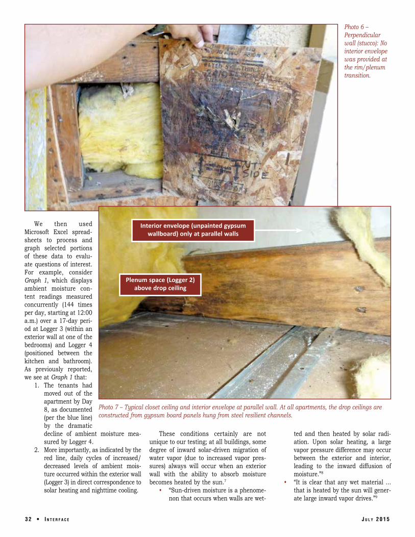
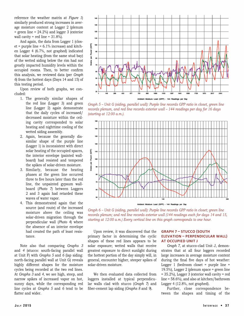
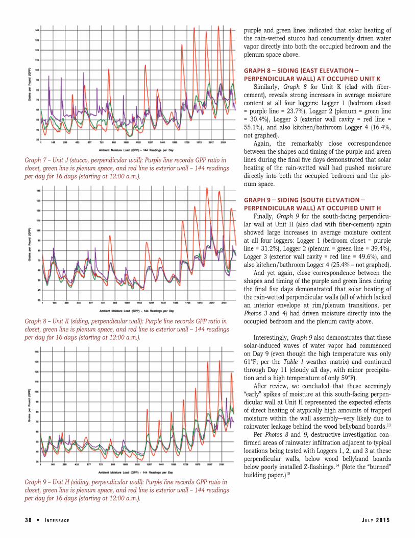