interfacing stepper motor with mc9s08lg32interfacing stepper motor with mc9s08lg32, rev. 1 stepper...
TRANSCRIPT
Freescale SemiconductorApplication Note
Document Number: AN3817Rev. 1, 2/2009
Contents
Introduction . . . . . . . . . . . . . . . . . . . . . . . . . . . . . . . . . . . 1Stepper Motor Management . . . . . . . . . . . . . . . . . . . . . . 2Operation and Functionality of Stepper Motor. . . . . . . . . 4Hardware Interface Description . . . . . . . . . . . . . . . . . . . . 6
4.1 Pin Connections . . . . . . . . . . . . . . . . . . . . . . . . . . . 64.2 Hardware Abstraction Layer . . . . . . . . . . . . . . . . . . 7
4.2.1 GPIO Registers. . . . . . . . . . . . . . . . . . . . . . . 74.2.2 TPM Registers . . . . . . . . . . . . . . . . . . . . . . . 8
4.3 Modes of Operation. . . . . . . . . . . . . . . . . . . . . . . . 104.3.1 4 GPIO Mode . . . . . . . . . . . . . . . . . . . . . . . 114.3.2 2 TPM + 2 GPIO Mode . . . . . . . . . . . . . . . . 114.3.3 3 GPIO Mode . . . . . . . . . . . . . . . . . . . . . . . 114.3.4 2 TPM + 1 GPIO Mode . . . . . . . . . . . . . . . . 12
Software Interface Description . . . . . . . . . . . . . . . . . . . 12Software Operation Modes . . . . . . . . . . . . . . . . . . . . . . 12How to Interface Stepper Motor with MC9S08LG32 . . . 13
7.1 Description of Motor (VID29 Series) . . . . . . . . . . . 137.1.1 Features of the Motor . . . . . . . . . . . . . . . . . 14
7.2 Hardware Connections . . . . . . . . . . . . . . . . . . . . . 147.3 Register Configurations . . . . . . . . . . . . . . . . . . . . . 14
7.3.1 Initialization Procedure . . . . . . . . . . . . . . . . 15References . . . . . . . . . . . . . . . . . . . . . . . . . . . . . . . . . . 16
Interfacing Stepper Motor with MC9S08LG32by: Sunaina Srivastava
Reference Design and Applications EngineeringMicrocontroller Solutions Group
1 IntroductionThe MC9S08LG32 is a low cost microcontroller and can be applied to several applications using different input signals. This application note:
• Describes how to control a low current stepper motor using the MC9S08LG32.
• Explains how to drive a stepper motor when there is no stepper motor driver within the MCU.
• Provides an example that illustrates the hardware connections and software driver for a stepper motor driven through PWM.
• Describes how to configure MC9S08LG32 to drive a stepper motor.
• Describes how the input signal is managed, implemented, and used.
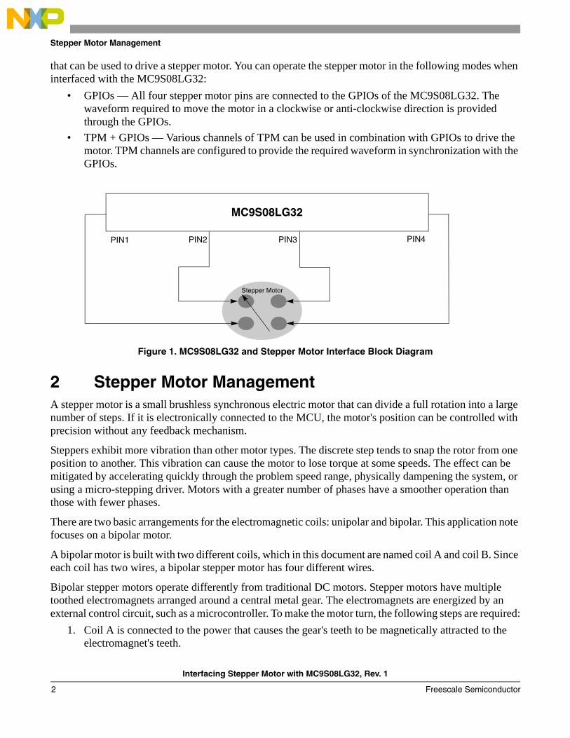
Figure 1 shows the block diagram for the MC9S08LG32 and stepper motor interface. The MC9S08LG32 contains 69 GPIOs (80-pin package) and eight channels of TPM
1234
567
8
© Freescale Semiconductor, Inc., 2009. All rights reserved.
Stepper Motor Management
that can be used to drive a stepper motor. You can operate the stepper motor in the following modes when interfaced with the MC9S08LG32:
• GPIOs — All four stepper motor pins are connected to the GPIOs of the MC9S08LG32. The waveform required to move the motor in a clockwise or anti-clockwise direction is provided through the GPIOs.
• TPM + GPIOs — Various channels of TPM can be used in combination with GPIOs to drive the motor. TPM channels are configured to provide the required waveform in synchronization with the GPIOs.
Figure 1. MC9S08LG32 and Stepper Motor Interface Block Diagram
2 Stepper Motor ManagementA stepper motor is a small brushless synchronous electric motor that can divide a full rotation into a large number of steps. If it is electronically connected to the MCU, the motor's position can be controlled with precision without any feedback mechanism.
Steppers exhibit more vibration than other motor types. The discrete step tends to snap the rotor from one position to another. This vibration can cause the motor to lose torque at some speeds. The effect can be mitigated by accelerating quickly through the problem speed range, physically dampening the system, or using a micro-stepping driver. Motors with a greater number of phases have a smoother operation than those with fewer phases.
There are two basic arrangements for the electromagnetic coils: unipolar and bipolar. This application note focuses on a bipolar motor.
A bipolar motor is built with two different coils, which in this document are named coil A and coil B. Since each coil has two wires, a bipolar stepper motor has four different wires.
Bipolar stepper motors operate differently from traditional DC motors. Stepper motors have multiple toothed electromagnets arranged around a central metal gear. The electromagnets are energized by an external control circuit, such as a microcontroller. To make the motor turn, the following steps are required:
1. Coil A is connected to the power that causes the gear's teeth to be magnetically attracted to the electromagnet's teeth.
MC9S08LG32
PIN1 PIN2 PIN3 PIN4
Stepper Motor
Interfacing Stepper Motor with MC9S08LG32, Rev. 1
Freescale Semiconductor2
Stepper Motor Management
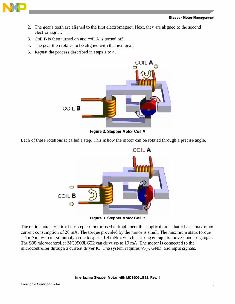
2. The gear's teeth are aligned to the first electromagnet. Next, they are aligned to the second electromagnet.
3. Coil B is then turned on and coil A is turned off.4. The gear then rotates to be aligned with the next gear.5. Repeat the process described in steps 1 to 4.
Figure 2. Stepper Motor Coil A
Each of these rotations is called a step. This is how the motor can be rotated through a precise angle.
Figure 3. Stepper Motor Coil B
The main characteristic of the stepper motor used to implement this application is that it has a maximum current consumption of 20 mA. The torque provided by the motor is small. The maximum static torque = 4 mNm, with maximum dynamic torque = 1.4 mNm, which is strong enough to move standard gauges. The S08 microcontroller MC9S08LG32 can drive up to 10 mA. The motor is connected to the microcontroller through a current driver IC. The system requires VCC, GND, and input signals.
Interfacing Stepper Motor with MC9S08LG32, Rev. 1
Freescale Semiconductor 3

Operation and Functionality of Stepper Motor
3 Operation and Functionality of Stepper MotorTo set the basis, the steps of the motor are managed by the duty cycle of a PWM input signal. The percentage of the duty cycle allows the microcontroller to communicate the specific position.
Figure 4. Complete Implemented System
Figure 5 is an example of the implemented system.
Figure 5. Complete Block Diagram of Motion Control
In the automotive industry, there are several sensors or applications that have a PWM signal as an output that is the result of a particular action or event. For example, there are complex temperature sensors that generate a PWM signal as output. Another example is an electronic central unit (ECU) that measures the speed of a vehicle and has an output pin where you can read a PWM signal. The variations of this PWM signal can be translated into positions to indicate temperature or speed, such as the application described in this document.
9
S
0
8
L
G
3
2
Current
DriverIC
Interfacing Stepper Motor with MC9S08LG32, Rev. 1
Freescale Semiconductor4

Operation and Functionality of Stepper Motor
Figure 6. Stepper Motor with Gauge
To define how many steps make up one complete cycle, you must first establish how many positions are available. In this example there are 100 different positions. In case of a temperature sensor, this could be from 0 °C to 100 °C. In case of speed, this could be 0 kph to 100 kph. This means that 1% of the duty cycle is associated with one step of the stepper motor, or one degree centigrade, or one kph. See Figure 7 and Figure 8.
Figure 7. Stepper Motor Gauges at Different Duty Cycles
The position of the gauge depends on the duty cycle of the PWM signal. There are different ways to translate duty cycles to steps. For example, the average voltage can be measured during one period of time using the ADC of the microcontroller. This document explains how to use the timer/pulse width modulator (TPM) module.
Interfacing Stepper Motor with MC9S08LG32, Rev. 1
Freescale Semiconductor 5
Hardware Interface Description
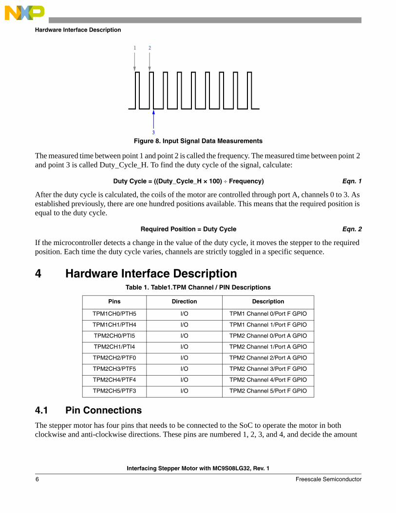
Figure 8. Input Signal Data Measurements
The measured time between point 1 and point 2 is called the frequency. The measured time between point 2 and point 3 is called Duty_Cycle_H. To find the duty cycle of the signal, calculate:
Duty Cycle = ((Duty_Cycle_H × 100) ÷ Frequency) Eqn. 1
After the duty cycle is calculated, the coils of the motor are controlled through port A, channels 0 to 3. As established previously, there are one hundred positions available. This means that the required position is equal to the duty cycle.
Required Position = Duty Cycle Eqn. 2
If the microcontroller detects a change in the value of the duty cycle, it moves the stepper to the required position. Each time the duty cycle varies, channels are strictly toggled in a specific sequence.
4 Hardware Interface Description
4.1 Pin ConnectionsThe stepper motor has four pins that needs to be connected to the SoC to operate the motor in both clockwise and anti-clockwise directions. These pins are numbered 1, 2, 3, and 4, and decide the amount
Table 1. Table1.TPM Channel / PIN Descriptions
Pins Direction Description
TPM1CH0/PTH5 I/O TPM1 Channel 0/Port F GPIO
TPM1CH1/PTH4 I/O TPM1 Channel 1/Port F GPIO
TPM2CH0/PTI5 I/O TPM2 Channel 0/Port A GPIO
TPM2CH1/PTI4 I/O TPM2 Channel 1/Port A GPIO
TPM2CH2/PTF0 I/O TPM2 Channel 2/Port A GPIO
TPM2CH3/PTF5 I/O TPM2 Channel 3/Port F GPIO
TPM2CH4/PTF4 I/O TPM2 Channel 4/Port F GPIO
TPM2CH5/PTF3 I/O TPM2 Channel 5/Port F GPIO
Interfacing Stepper Motor with MC9S08LG32, Rev. 1
Freescale Semiconductor6
Hardware Interface Description
and direction of the rotation of the motor. Figure 24 shows the sample connection of stepper motor pins with the MC9S08LG32 SoC.
4.2 Hardware Abstraction LayerThis section describes the registers that you need to operate a stepper motor in all possible driving modes with the MC9S08LG32.
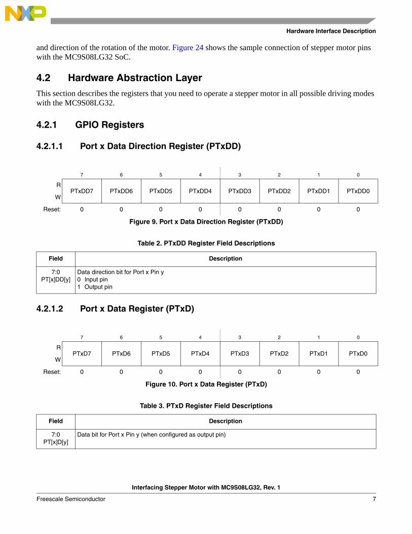
4.2.1 GPIO Registers
4.2.1.1 Port x Data Direction Register (PTxDD)
4.2.1.2 Port x Data Register (PTxD)
7 6 5 4 3 2 1 0
RPTxDD7 PTxDD6 PTxDD5 PTxDD4 PTxDD3 PTxDD2 PTxDD1 PTxDD0
W
Reset: 0 0 0 0 0 0 0 0
Figure 9. Port x Data Direction Register (PTxDD)
Table 2. PTxDD Register Field Descriptions
Field Description
7:0PT[x]DD[y]
Data direction bit for Port x Pin y0 Input pin1 Output pin
7 6 5 4 3 2 1 0
RPTxD7 PTxD6 PTxD5 PTxD4 PTxD3 PTxD2 PTxD1 PTxD0
W
Reset: 0 0 0 0 0 0 0 0
Figure 10. Port x Data Register (PTxD)
Table 3. PTxD Register Field Descriptions
Field Description
7:0PT[x]D[y]
Data bit for Port x Pin y (when configured as output pin)
Interfacing Stepper Motor with MC9S08LG32, Rev. 1
Freescale Semiconductor 7
Hardware Interface Description
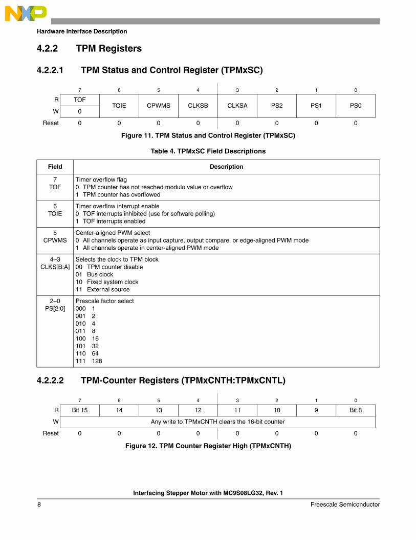
4.2.2 TPM Registers
4.2.2.1 TPM Status and Control Register (TPMxSC)
4.2.2.2 TPM-Counter Registers (TPMxCNTH:TPMxCNTL)
7 6 5 4 3 2 1 0
R TOFTOIE CPWMS CLKSB CLKSA PS2 PS1 PS0
W 0
Reset 0 0 0 0 0 0 0 0
Figure 11. TPM Status and Control Register (TPMxSC)
Table 4. TPMxSC Field Descriptions
Field Description
7TOF
Timer overflow flag0 TPM counter has not reached modulo value or overflow1 TPM counter has overflowed
6TOIE
Timer overflow interrupt enable0 TOF interrupts inhibited (use for software polling)1 TOF interrupts enabled
5CPWMS
Center-aligned PWM select0 All channels operate as input capture, output compare, or edge-aligned PWM mode1 All channels operate in center-aligned PWM mode
4–3CLKS[B:A]
Selects the clock to TPM block00 TPM counter disable01 Bus clock10 Fixed system clock11 External source
2–0PS[2:0]
Prescale factor select000 1001 2010 4011 8100 16101 32110 64111 128
7 6 5 4 3 2 1 0
R Bit 15 14 13 12 11 10 9 Bit 8
W Any write to TPMxCNTH clears the 16-bit counter
Reset 0 0 0 0 0 0 0 0
Figure 12. TPM Counter Register High (TPMxCNTH)
Interfacing Stepper Motor with MC9S08LG32, Rev. 1
Freescale Semiconductor8
Hardware Interface Description
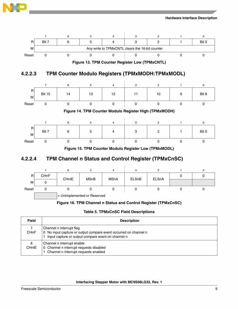
4.2.2.3 TPM Counter Modulo Registers (TPMxMODH:TPMxMODL)
4.2.2.4 TPM Channel n Status and Control Register (TPMxCnSC)
7 6 5 4 3 2 1 0
R Bit 7 6 5 4 3 2 1 Bit 0
W Any write to TPMxCNTL clears the 16-bit counter
Reset 0 0 0 0 0 0 0 0
Figure 13. TPM Counter Register Low (TPMxCNTL)
7 6 5 4 3 2 1 0
RBit 15 14 13 12 11 10 9 Bit 8
W
Reset 0 0 0 0 0 0 0 0
Figure 14. TPM Counter Modulo Register High (TPMxMODH)
7 6 5 4 3 2 1 0
RBit 7 6 5 4 3 2 1 Bit 0
W
Reset 0 0 0 0 0 0 0 0
Figure 15. TPM Counter Modulo Register Low (TPMxMODL)
7 6 5 4 3 2 1 0
R CHnFCHnIE MSnB MSnA ELSnB ELSnA
0 0
W 0
Reset 0 0 0 0 0 0 0 0
= Unimplemented or Reserved
Figure 16. TPM Channel n Status and Control Register (TPMxCnSC)
Table 5. TPMxCnSC Field Descriptions
Field Description
7CHnF
Channel n interrupt flag0 No input capture or output compare event occurred on channel n1 Input capture or output compare event on channel n
6CHnIE
Channel n interrupt enable0 Channel n interrupt requests disabled1 Channel n interrupt requests enabled
Interfacing Stepper Motor with MC9S08LG32, Rev. 1
Freescale Semiconductor 9
Hardware Interface Description
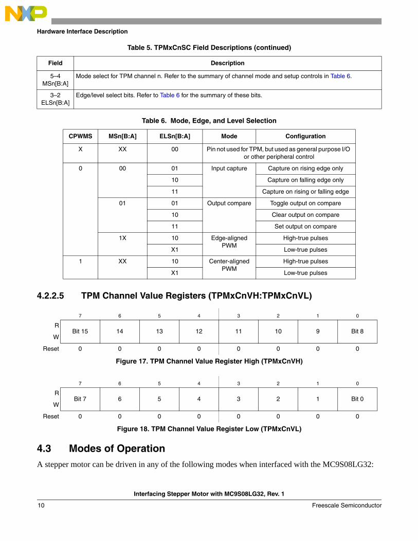
4.2.2.5 TPM Channel Value Registers (TPMxCnVH:TPMxCnVL)
4.3 Modes of OperationA stepper motor can be driven in any of the following modes when interfaced with the MC9S08LG32:
5–4MSn[B:A]
Mode select for TPM channel n. Refer to the summary of channel mode and setup controls in Table 6.
3–2ELSn[B:A]
Edge/level select bits. Refer to Table 6 for the summary of these bits.
Table 6. Mode, Edge, and Level Selection
CPWMS MSn[B:A] ELSn[B:A] Mode Configuration
X XX 00 Pin not used for TPM, but used as general purpose I/O or other peripheral control
0 00 01 Input capture Capture on rising edge only
10 Capture on falling edge only
11 Capture on rising or falling edge
01 01 Output compare Toggle output on compare
10 Clear output on compare
11 Set output on compare
1X 10 Edge-aligned PWM
High-true pulses
X1 Low-true pulses
1 XX 10 Center-aligned PWM
High-true pulses
X1 Low-true pulses
7 6 5 4 3 2 1 0
RBit 15 14 13 12 11 10 9 Bit 8
W
Reset 0 0 0 0 0 0 0 0
Figure 17. TPM Channel Value Register High (TPMxCnVH)
7 6 5 4 3 2 1 0
RBit 7 6 5 4 3 2 1 Bit 0
W
Reset 0 0 0 0 0 0 0 0
Figure 18. TPM Channel Value Register Low (TPMxCnVL)
Table 5. TPMxCnSC Field Descriptions (continued)
Field Description
Interfacing Stepper Motor with MC9S08LG32, Rev. 1
Freescale Semiconductor10
Hardware Interface Description
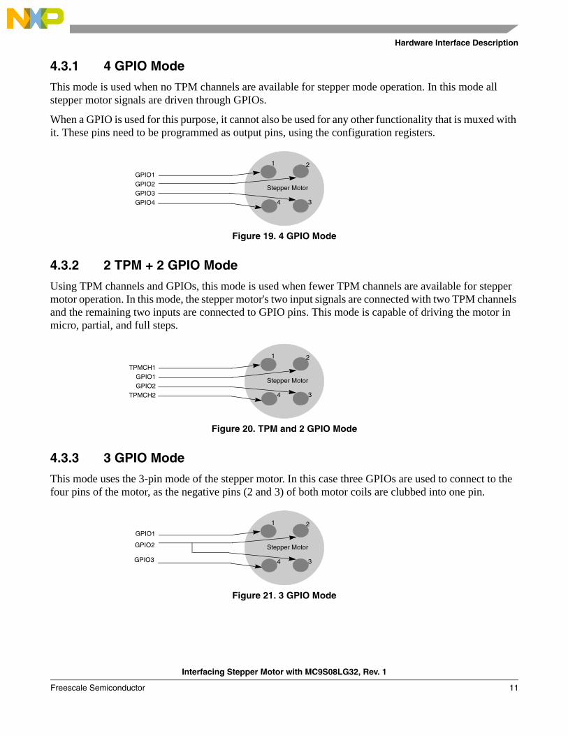
4.3.1 4 GPIO Mode
This mode is used when no TPM channels are available for stepper mode operation. In this mode all stepper motor signals are driven through GPIOs.
When a GPIO is used for this purpose, it cannot also be used for any other functionality that is muxed with it. These pins need to be programmed as output pins, using the configuration registers.
Figure 19. 4 GPIO Mode
4.3.2 2 TPM + 2 GPIO Mode
Using TPM channels and GPIOs, this mode is used when fewer TPM channels are available for stepper motor operation. In this mode, the stepper motor's two input signals are connected with two TPM channels and the remaining two inputs are connected to GPIO pins. This mode is capable of driving the motor in micro, partial, and full steps.
Figure 20. TPM and 2 GPIO Mode
4.3.3 3 GPIO Mode
This mode uses the 3-pin mode of the stepper motor. In this case three GPIOs are used to connect to the four pins of the motor, as the negative pins (2 and 3) of both motor coils are clubbed into one pin.
Figure 21. 3 GPIO Mode
Stepper Motor
GPIO1GPIO2GPIO3GPIO4
1 2
34
Stepper Motor
TPMCH1GPIO1GPIO2
TPMCH2
1 2
34
Stepper Motor
GPIO1
GPIO2
1 2
34GPIO3
Interfacing Stepper Motor with MC9S08LG32, Rev. 1
Freescale Semiconductor 11
Software Interface Description
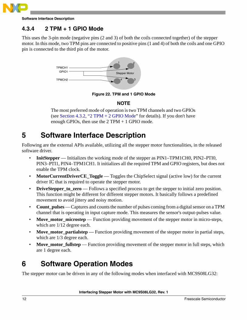
4.3.4 2 TPM + 1 GPIO Mode
This uses the 3-pin mode (negative pins (2 and 3) of both the coils connected together) of the stepper motor. In this mode, two TPM pins are connected to positive pins (1 and 4) of both the coils and one GPIO pin is connected to the third pin of the motor.
Figure 22. TPM and 1 GPIO Mode
NOTEThe most preferred mode of operation is two TPM channels and two GPIOs (see Section 4.3.2, “2 TPM + 2 GPIO Mode” for details). If you don't have enough GPIOs, then use the 2 TPM + 1 GPIO mode.
5 Software Interface DescriptionFollowing are the external APIs available, utilizing all the stepper motor functionalities, in the released software driver.
• InitStepper — Initializes the working mode of the stepper as PIN1–TPM1CH0, PIN2–PTI0, PIN3–PTI1, PIN4–TPM1CH1. It initializes all the required TPM and GPIO registers, but does not enable the TPM clock.
• MotorCurrentDriverCE_Toggle — Toggles the ChipSelect signal (active low) for the current driver IC that is required to operate the stepper motor.
• DriveStepper_to_zero — Follows a specified process to get the stepper to initial zero position. This function might be different for different stepper motors. It basically follows a predefined movement to avoid jittery and noisy motion.
• Count_pulses — Captures and counts the number of pulses coming from a digital sensor on a TPM channel that is operating in input capture mode. This measures the sensor's output-pulses value.
• Move_motor_microstep — Function providing movement of the stepper motor in micro-steps, which are 1/12 degree each.
• Move_motor_partialstep — Function providing movement of the stepper motor in partial steps, which are 1/3 degree each.
• Move_motor_fullstep — Function providing movement of the stepper motor in full steps, which are 1 degree each.
6 Software Operation ModesThe stepper motor can be driven in any of the following modes when interfaced with MC9S08LG32:
Stepper Motor
TPMCH1GPIO1
1 2
34TPMCH2
Interfacing Stepper Motor with MC9S08LG32, Rev. 1
Freescale Semiconductor12
How to Interface Stepper Motor with MC9S08LG32
• Full step mode• Partial step mode• Micro-stepping mode• Acceleration process at power-on or power-on reset
In most of the VID29-XX applications, the angular range of the instrument dial is less than 300°. This allows you to use mechanical stop to define the zero position. Generally the pointer will be reset to the zero position at each power-up process. In the power-up process, we recommend a frequency acceleration process to speed up the VID29 step motor until a high speed is reached. This will quickly drive the pointer to its initial stop position without creating visible and audible jitter of the pointer.
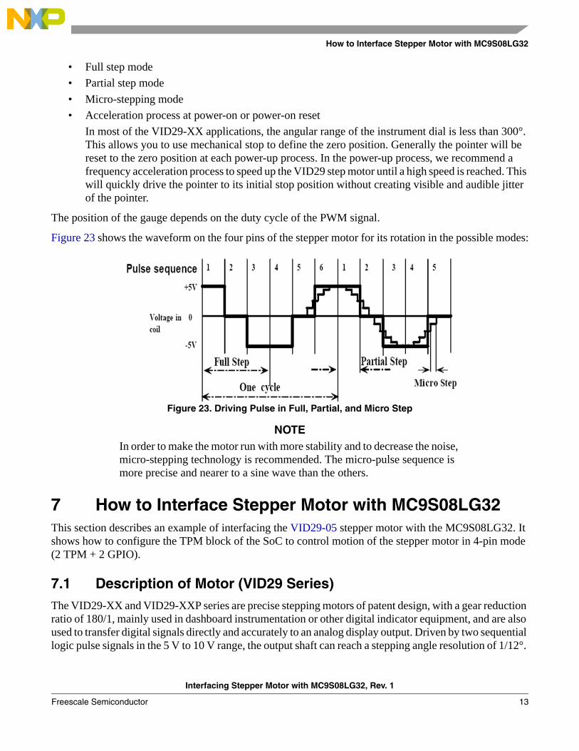
The position of the gauge depends on the duty cycle of the PWM signal.
Figure 23 shows the waveform on the four pins of the stepper motor for its rotation in the possible modes:
Figure 23. Driving Pulse in Full, Partial, and Micro Step
NOTEIn order to make the motor run with more stability and to decrease the noise, micro-stepping technology is recommended. The micro-pulse sequence is more precise and nearer to a sine wave than the others.
7 How to Interface Stepper Motor with MC9S08LG32This section describes an example of interfacing the VID29-05 stepper motor with the MC9S08LG32. It shows how to configure the TPM block of the SoC to control motion of the stepper motor in 4-pin mode (2 TPM + 2 GPIO).
7.1 Description of Motor (VID29 Series)The VID29-XX and VID29-XXP series are precise stepping motors of patent design, with a gear reduction ratio of 180/1, mainly used in dashboard instrumentation or other digital indicator equipment, and are also used to transfer digital signals directly and accurately to an analog display output. Driven by two sequential logic pulse signals in the 5 V to 10 V range, the output shaft can reach a stepping angle resolution of 1/12°.
Interfacing Stepper Motor with MC9S08LG32, Rev. 1
Freescale Semiconductor 13
How to Interface Stepper Motor with MC9S08LG32
The angular speed can reach more than 500 Hz. The new and modern design makes for high efficiency, high position accuracy, and an extremely robust gear system. The special gear shape helps to decrease friction and noise. Special materials have been chosen for each component to increase the reliability and safety of the motor.
7.1.1 Features of the Motor• Wide working voltage: 5 V to 10 V• Low current consumption: less than 20 mA, 5 V, 2 × 100 mW• Wide working temperature: –40 °C to 105 °C• Extremely robust construction: 30 mm × 7.6 mm• High micro-step resolution: 1/12°• Directly driven by MCU
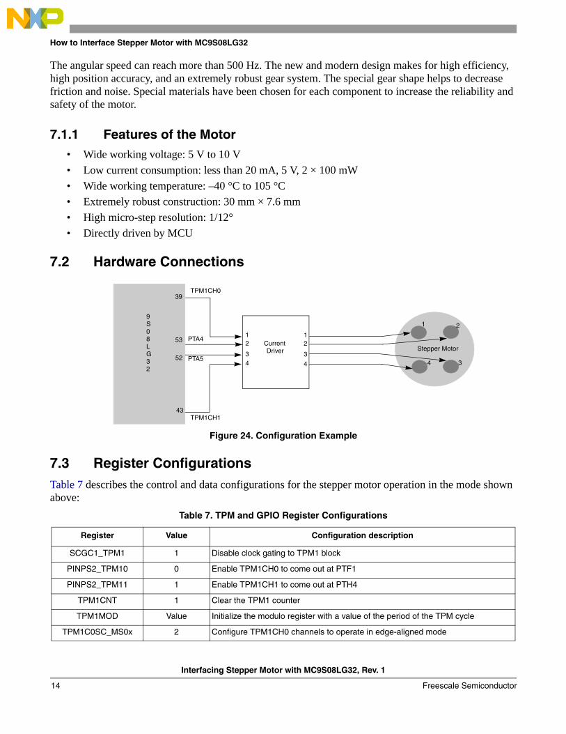
7.2 Hardware Connections
Figure 24. Configuration Example
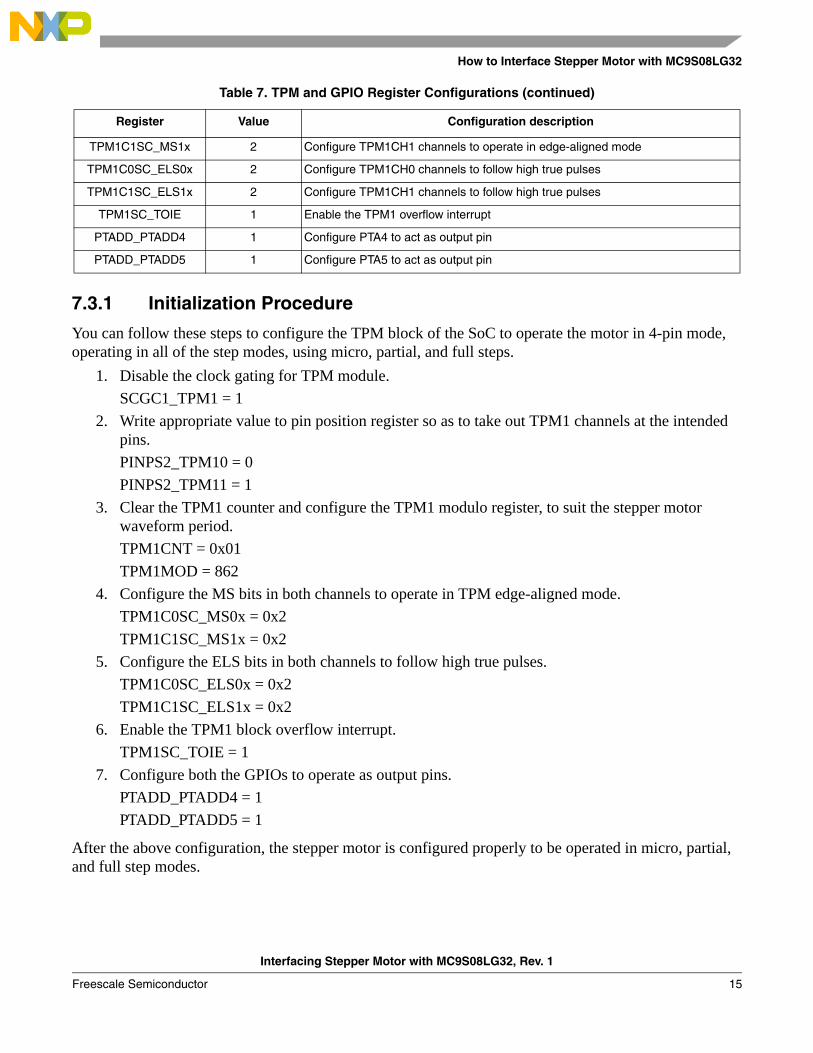
7.3 Register ConfigurationsTable 7 describes the control and data configurations for the stepper motor operation in the mode shown above:
Table 7. TPM and GPIO Register Configurations
Register Value Configuration description
SCGC1_TPM1 1 Disable clock gating to TPM1 block
PINPS2_TPM10 0 Enable TPM1CH0 to come out at PTF1
PINPS2_TPM11 1 Enable TPM1CH1 to come out at PTH4
TPM1CNT 1 Clear the TPM1 counter
TPM1MOD Value Initialize the modulo register with a value of the period of the TPM cycle
TPM1C0SC_MS0x 2 Configure TPM1CH0 channels to operate in edge-aligned mode
Stepper Motor
1 2
34
1 12 2
3 34 4
CurrentDriver
9S08LG32
39
53
52
43
TPM1CH0
PTA4
PTA5
TPM1CH1
Interfacing Stepper Motor with MC9S08LG32, Rev. 1
Freescale Semiconductor14
How to Interface Stepper Motor with MC9S08LG32
7.3.1 Initialization Procedure
You can follow these steps to configure the TPM block of the SoC to operate the motor in 4-pin mode, operating in all of the step modes, using micro, partial, and full steps.
1. Disable the clock gating for TPM module.SCGC1_TPM1 = 1
2. Write appropriate value to pin position register so as to take out TPM1 channels at the intended pins.PINPS2_TPM10 = 0PINPS2_TPM11 = 1
3. Clear the TPM1 counter and configure the TPM1 modulo register, to suit the stepper motor waveform period.TPM1CNT = 0x01TPM1MOD = 862
4. Configure the MS bits in both channels to operate in TPM edge-aligned mode.TPM1C0SC_MS0x = 0x2TPM1C1SC_MS1x = 0x2
5. Configure the ELS bits in both channels to follow high true pulses.TPM1C0SC_ELS0x = 0x2TPM1C1SC_ELS1x = 0x2
6. Enable the TPM1 block overflow interrupt.TPM1SC_TOIE = 1
7. Configure both the GPIOs to operate as output pins.PTADD_PTADD4 = 1PTADD_PTADD5 = 1
After the above configuration, the stepper motor is configured properly to be operated in micro, partial, and full step modes.
TPM1C1SC_MS1x 2 Configure TPM1CH1 channels to operate in edge-aligned mode
TPM1C0SC_ELS0x 2 Configure TPM1CH0 channels to follow high true pulses
TPM1C1SC_ELS1x 2 Configure TPM1CH1 channels to follow high true pulses
TPM1SC_TOIE 1 Enable the TPM1 overflow interrupt
PTADD_PTADD4 1 Configure PTA4 to act as output pin
PTADD_PTADD5 1 Configure PTA5 to act as output pin
Table 7. TPM and GPIO Register Configurations (continued)
Register Value Configuration description
Interfacing Stepper Motor with MC9S08LG32, Rev. 1
Freescale Semiconductor 15
References
8 ReferencesSee S08LG Product Summary Page for more information and the documents released for MC9S08LG32.
Interfacing Stepper Motor with MC9S08LG32, Rev. 1
Freescale Semiconductor16

THIS PAGE IS INTENTIONALLY BLANK
Interfacing Stepper Motor with MC9S08LG32, Rev. 1
Freescale Semiconductor 17
Document Number: AN3817Rev. 12/2009
How to Reach Us:
Home Page:www.freescale.com
Web Support:http://www.freescale.com/support
USA/Europe or Locations Not Listed:Freescale Semiconductor, Inc.Technical Information Center, EL5162100 East Elliot RoadTempe, Arizona 85284+1-800-521-6274 or +1-480-768-2130www.freescale.com/support
Europe, Middle East, and Africa:Freescale Halbleiter Deutschland GmbHTechnical Information CenterSchatzbogen 781829 Muenchen, Germany+44 1296 380 456 (English)+46 8 52200080 (English)+49 89 92103 559 (German)+33 1 69 35 48 48 (French)www.freescale.com/support
Japan:Freescale Semiconductor Japan Ltd.HeadquartersARCO Tower 15F1-8-1, Shimo-Meguro, Meguro-ku,Tokyo 153-0064Japan0120 191014 or +81 3 5437 [email protected]
Asia/Pacific:Freescale Semiconductor China Ltd.Exchange Building 23FNo. 118 Jianguo RoadChaoyang DistrictBeijing 100022 China +86 10 5879 [email protected]
For Literature Requests Only:Freescale Semiconductor Literature Distribution CenterP.O. Box 5405Denver, Colorado 802171-800-441-2447 or 303-675-2140Fax: [email protected]
Information in this document is provided solely to enable system and software implementers to use Freescale Semiconductor products. There are no express or implied copyright licenses granted hereunder to design or fabricate any integrated circuits or integrated circuits based on the information in this document.
Freescale Semiconductor reserves the right to make changes without further notice to any products herein. Freescale Semiconductor makes no warranty, representation or guarantee regarding the suitability of its products for any particular purpose, nor does Freescale Semiconductor assume any liability arising out of the application or use of any product or circuit, and specifically disclaims any and all liability, including without limitation consequential or incidental damages. “Typical” parameters that may be provided in Freescale Semiconductor data sheets and/or specifications can and do vary in different applications and actual performance may vary over time. All operating parameters, including “Typicals”, must be validated for each customer application by customer’s technical experts. Freescale Semiconductor does not convey any license under its patent rights nor the rights of others. Freescale Semiconductor products are not designed, intended, or authorized for use as components in systems intended for surgical implant into the body, or other applications intended to support or sustain life, or for any other application in which the failure of the Freescale Semiconductor product could create a situation where personal injury or death may occur. Should Buyer purchase or use Freescale Semiconductor products for any such unintended or unauthorized application, Buyer shall indemnify and hold Freescale Semiconductor and its officers, employees, subsidiaries, affiliates, and distributors harmless against all claims, costs, damages, and expenses, and reasonable attorney fees arising out of, directly or indirectly, any claim of personal injury or death associated with such unintended or unauthorized use, even if such claim alleges that Freescale Semiconductor was negligent regarding the design or manufacture of the part.
RoHS-compliant and/or Pb-free versions of Freescale products have the functionality and electrical characteristics as their non-RoHS-compliant and/or non-Pb-free counterparts. For further information, see http://www.freescale.com or contact your Freescale sales representative.
For information on Freescale’s Environmental Products program, go to http://www.freescale.com/epp.
Freescale™ and the Freescale logo are trademarks of Freescale Semiconductor, Inc. All other product or service names are the property of their respective owners.© Freescale Semiconductor, Inc. 2009. All rights reserved.