interference mitigation for cognitive radio mimo systems ... · interference mitigation for...
TRANSCRIPT

Interference Mitigation for Cognitive Radio MIMO
Systems Based on Practical Precoding
(Invited Paper)
Zengmao Chena, Cheng-Xiang Wanga,∗, Xuemin Hongb, John Thompsonc,Sergiy A. Vorobyovd, Feng Zhaoe, Xiaohu Gef
aJoint Research Institute for Signal and Image Processing, School of Engineering andPhysical Sciences, Heriot-Watt University, Edinburgh, EH14 4AS, UK.
bSchool of Information Science and Technology, Xiamen University, Xiamen 361005,China
cJoint Research Institute for Signal and Image Processing, Institute for DigitalCommunications, University of Edinburgh,Edinburgh, EH9 3JL, UK.
dDepartment of Electrical and Computer Engineering, University of Alberta, Edmonton,AB, T6G 2V4, Canada.
eDepartment of Science and Technology, Guilin University of Electronic Technology,Guilin 541004, China.
fDepartment of Electronics and Information Engineering, Huazhong University ofScience and Technology, Wuhan 430074, China.
Abstract
In this paper, we propose two subspace-projection-based precoding schemes,
namely, full-projection (FP)- and partial-projection (PP)-based precoding,
for a cognitive radio multiple-input multiple-output (CR-MIMO) network to
mitigate its interference to a primary time-division-duplexing (TDD) system.
The proposed precoding schemes are capable of estimating interference chan-
nels between CR and primary networks, and incorporating the interference
∗Corresponding author. Tel.: +44 131 451 3329.Email addresses: [email protected] (Zengmao Chen),
[email protected] (Cheng-Xiang Wang), [email protected] (XueminHong), [email protected] (John Thompson), [email protected] (Sergiy A.Vorobyov), [email protected] (Feng Zhao), [email protected] (Xiaohu Ge)
Preprint submitted to Elsevier Physical Communication April 27, 2012

from the primary to the CR system into CR precoding via a novel sensing
approach. Then, the CR performance and resulting interference of the pro-
posed precoding schemes are analyzed and evaluated. By fully projecting
the CR transmission onto a null space of the interference channels, the FP-
based precoding scheme can effectively avoid interfering the primary system
with boosted CR throughput. While, the PP-based scheme is able to further
improve the CR throughput by partially projecting its transmission onto the
null space.
Keywords:
Cognitive radio, interference mitigation, MIMO, precoding
1. Introduction
A cognitive radio (CR) [1]–[4] system may coexist with a primary net-
work on an either interference-free or interference-tolerant basis [5, 6]. For
the former case, the CR system only exploits the unused spectra of the pri-
mary network. While, for the latter case, the CR system is allowed to share
the spectra assigned to primary network under the condition of not imposing
detrimental interference on the primary network. Therefore, the interfer-
ence from the CR network to the primary system (CR-primary interference)
should be carefully managed and cancelled in order to protect the operation
of the primary system. Various interference mitigation (IM) techniques ap-
plicable to CR networks have been reported in [7]. As for multiple-antenna
CR networks, transmit beamforming [8]–[12] or precoding [13]–[15] is an ef-
fective approach to proactively cancel the CR-primary interference. On one
hand, it steers the CR transmission to avoid interfering with the primary
2

network. On the other hand, it exploits the diversity or the multiplexing
gain of CR system to enhance the reliability or efficiency of the CR network.
However, in the references [8]–[15], perfect or partial channel state infor-
mation (CSI) of CR interference channels to primary network (CR-primary
interference channels) is required at the CR transmitter (Tx) side to guar-
antee no/constrained interference to the primary system. Therefore, ex-
tra signaling between primary and CR networks is inevitable to obtain the
CSI, which jeopardizes the applicability of these beamforming and precoding
schemes. A more practical precoding scheme - sensing projection (SP)-based
precoding, which learns the CSI using subspace estimation [16] and does not
require a priori CSI, has been proposed for a CR multiple-input multiple-
output (MIMO) link coexisting with a primary time-division-duplexing (TDD)
system in [17, 18]. However, such precoding scheme does not account for the
interference from primary Txs to the CR receiver (Rx) (primary-CR interfer-
ence), which leads to a CR throughput loss. In [19] and [20], it is proposed to
remove the primary-CR interference at the CR Rx via null-space Rx beam-
forming, which sacrifices the CR throughput as well. Moreover, the CR
network in [19, 20] has to work in a TDD mode aligned with the primary
system in order to facilitate the null-space Rx beamforming.
In this paper, two enhanced SP-based precoding schemes, namely, full-
projection (FP)- and partial-projection (PP)-based precoding, are proposed
for CR MIMO systems by incorporating the primary-CR interference. As
the name suggests, the FP-based scheme nulls the CR transmission by fully
projecting the transmission onto the estimated null space of the CR-primary
interference channels. Instead of removing the primary-CR interference us-
3

ing null-space Rx beamforming, the proposed precoding schemes account for
the primary-CR interference via sensing. This, on one hand, improves the
CR throughput, and on the other hand, introduces more flexibility into the
CR deployment, i.e., the CR network does not have to work in a TDD mode
as in [19, 20]. The PP-based precoding can further improve the CR through-
put by projecting the CR transmission onto a subspace that partially spans
the estimated null space of the CR-primary interference channels. As a re-
sult, the CR throughput is further improved at the cost of introducing extra
interference to the primary network.
The remainder of this paper is organised as follows. The system model
is given in Section 2. The working principle of the SP-based precoding is
introduced in Section 3. Then, we propose two new precoding schemes in
Section 4. The performance of the proposed precoding schemes is evaluated
in Section 5. Finally, we conclude the paper in Section 6.
Notation: Vectors are denoted by bold-face lower-case letters, e.g., x,
and bold-face upper-case letters are used for matrices, e.g., X. For a matrix
X, Tr{X}, XH , and X† denote its trace, Hermitian transpose and pseudoin-
verse, respectively. E{·} stands for the statistical expectation operator. Cx×y
denotes the space of x× y matrices with complex entries.
2. System Model and Problem Formulation
We consider a CR system shown in Fig. 1, where a CR Tx-Rx pair shares
the same spectrum with a primary TDD network. Multiple antennas are
mounted at the CR nodes and possibly at each of the primary users. The
CR Tx, CR Rx, primary base station (BS) and the kth primary user are
4

equipped with Mt, Mr, Mbs and Mk (k = 1, · · · , K) antennas, respectively.
Block-fading channels are assumed for the primary and CR systems.
For a narrowband transmission, the received symbol at the CR Rx can
be expressed as
y = HFs+ n+ z (1)
where y ∈ CMr×1 is the received signal vector at the CR Rx, s ∈ CMt×1
and F ∈ CMt×Mt are the transmit information vector with E{ssH} = I and
precoding matrix of the CR Tx, respectively, H ∈ CMr×Mt is the channel
matrix from the CR Tx to CR Rx, whose elements are independent and
identically distributed (i.i.d.) complex Gaussian random variables with zero
mean and variance σ2H , and n ∈ CMr×1 stands for the additive white Gaussian
noise (AWGN) vector with zero mean and covariance matrix E{nnH} = σ2nI.
Moreover, z ∈ CMr×1 denotes the interference from the primary network to
CR Rx. It can be expressed as
z =
Hurxu, during primary uplink
Hdrxd, during primary downlink(2)
where Hur ∈ CMr×∑K
k=1 Mk and Hut ∈ CMt×∑K
k=1 Mk (see Fig. 1) represent
the interference channels from all the K active primary users to CR Rx and
to CR Tx, respectively, during primary uplink. Similarly, Hdr ∈ CMr×Mbs
in (2) together with Hdt ∈ CMt×Mbs (see Fig. 1) stand for the interference
matrices from the primary BS to CR Rx and to CR Tx during primary
downlink. All these interference matrices (Hur, Hut, Hdr and Hdt) have i.i.d.
complex Gaussian random elements with zero mean and covariances σ2ur, σ
2ut,
σ2dr and σ2
dt, respectively. Moreover, xu ∈ C∑K
k=1 Mk×1 and xd ∈ CMbs×1 are
5

the transmitted signal vectors of all the K primary users and primary BS,
respectively. We define the interference covariance matrix as Z , E{zzH}.
3. Principle of SP-based Precoding
The precoding problem for CR transmission can be expressed as the fol-
lowing optimisation problem [14]
maxF
log2det
(I+
HFFHHH
σ2n
)(3)
subject to Tr{FFH} ≤ Pcr (4)
Tr{GkFFHGH
k } ≤ Γk k = 1, . . . , K. (5)
In (5), Gk ∈ CMk×Mt is the channel matrix from the CR Tx to the kth
primary user. Thus, the channel matrix from the CR Tx to all primary users
becomesHHut=[GT
1 , · · · ,GTK ]
T due to channel reciprocity. The constraints on
the CR transmission power and the maximum allowed interference perceived
at each primary user are given by (4) and (5), respectively.
The projected channel singular value decomposition (SVD) or P-SVD
precoding has been proposed in [14] as a suboptimal solution for the optimi-
sation problem (3)–(5). It can be expressed as
F = U⊥[(µI−Λ−1
⊥ )+] 1
2 (6)
where (·)+ = max(0, ·), µ denotes the power level for a water-filling (WF) al-
gorithm, and U⊥ and Λ⊥ originate from the SVD of the effective CR channel
matrix H⊥
H⊥ , H(I−UGUHG ), (7)
withH⊥ = V⊥Λ1/2⊥ UH
⊥ , andUG in (7) is from another SVDHHut = VGΛ
1/2G UH
G ,
which is estimated via sensing in the SP precoding [17, 18] as shown in Fig. 2.
6

It is worth noting that the P-SVD precoding given in (6) actually garantees
that Tr{GkFFHGH
k } = 0 (k = 1, . . . , K), i.e., no interference is introduced
to primary users. This eventually tightens the constraint (5). Therefore,
the P-SVD precoding is a suboptimal solution for the optimisation problem
(3)–(5).
By analogy with the multiple signal classification technique [16], the signal
covariance matrix is decomposed into signal and noise subspaces to estimate
UG, that is
Rut =1
LS
LS∑i=1
rut(i)rHut(i) (8)
= UΛUH (9)
= UGΛGUHG + UnΛnU
Hn . (10)
In (16), rut(i) = Hutxu(i)+n(i) is the ith received symbol at the CR Tx, and
its estimated covariance matrix is denoted as Rut. An eigenvalue decompo-
sition is then performed on Rut in (17), where Λ = diag(λ1, · · · , λMt) is a di-
agonal matrix with descendingly ordered eigenvalues of Rut and U ∈ CMt×Mt
contains the corresponding eigenvectors. The matrix Rut is further decom-
posed into interference and noise components in (18) with UG and Un being
the first Kp = rank(Hut) and the remaining (Mt−Kp) columns of U, re-
spectively, and ΛG and Λn being their corresponding eigenvalue matrices. A
rank estimate for Kp can be carried out by using, e.g., an Akaike information
criterion (AIC) or minimum description length (MDL) estimator [21]. The
sensing phase is followed by a CR transmission, where a precoding matrix
obtained from (6) is applied.
The merit of the SP precoding over the P-SVD approach is that no CSI is
7

required due to the interference space estimation in (16)–(18). However, both
of the precoding algorithms in [17] and [18] do not consider the interference
from the primary network to the CR receiver, which eventually leads to rate
loss for the CR link.
4. Proposed Precoding Schemes
In this section, we elaborate the CR precoding during the primary down-
link1. When incorporating the primary-CR interference, the precoding prob-
lem for the CR Tx during the primary downlink can be expressed as follows
maxF
log2det
(I+
HFFHHH
Z+ σ2nI
)(11)
subject to Tr{FFH} ≤ Pcr (12)
Tr{GkFFHGH
k } ≤ Γk, k = 1, . . . , K. (13)
The constraints on the CR transmission power and the maximum allowed
interference perceived at each primary user are given by (12) and (13), re-
spectively. In (13), Gk ∈ CMk×Mt is the channel matrix from the CR Tx
to the kth primary user. Thus, the channel matrix from the CR Tx to all
primary users becomes HHut=[GT
1 , · · · ,GTK ]
T due to channel reciprocity.
Then, the precoding matrix for CR transmission during the downlink can
be written as
Fd = Ud
[(µdI−Λ−1
d )+] 1
2 (14)
1A similar precoding for the primary uplink can be easily obtained, which is ignored
here for brevity.
8

where µd is the power level for the water-filling algorithm and Ud is obtained
through the following eigenvalue decomposition (EVD)
UdΛdUHd = HH
⊥ (Z+ σ2nI)
−1H⊥
= (I−UGUHG )
HHH(Z+ σ2nI)
−1H(I−UGUHG ). (15)
Similar to the P-SVD precoding, the precoding matrix given by (14) is a
suboptimal solution for the optimisation problem (11)-(13) due to the fact
that it tightens the constraint (13) by forcing Γk to 0.
In (15), the effective CR channel matrix is defined asH⊥ , H(I−UGUHG ),
where UG is estimated by decompositing the CR received signal covariance
matrix into signal and noise subspaces. It can be expressed as
Rut =1
LS
LS∑i=1
rut(i)rHut(i) (16)
= UΛUH (17)
= UGΛGUHG + UnΛnU
Hn . (18)
In (16), rut(i) = Hutxu(i) + n(i) is the ith received symbol at the CR Tx,
and its estimated covariance matrix is denoted as Rut. An EVD is then
performed on Rut in (17), where Λ = diag(λ1, · · · , λMt) is a diagonal matrix
with descendingly ordered eigenvalues of Rut. It is further decomposed into
interference and noise components in (18) with UG and Un being the first
Kp = rank(Hut) and the remaining (Mt−Kp) columns of U, respectively,
and ΛG and Λn being their corresponding eigenvalue matrices.
It can be seen from (14) and (15) that in order to obtain the CR precoding
matrix, the interference-plus-noise covariance matrix Rur , Z + σ2nI needs
9

to be estimated at the CR Rx, besides the estimation of the interference
subspace UGUHG at the CR Tx.
4.1. Full-projection-based precoding
To enable the estimation of UGUHG and Rur, we propose an enhanced
precoding scheme, which is demonstrated in Fig. 2. Each CR cycle consists
of sensing and transmission phases. We name the CR transmission during
the primary downlink as T1 and uplink as T2. For T1, the space UGUHG
is estimated at the CR Tx during the primary uplink according to (16)–
(18) over LS1 symbols. The estimation of Rur is performed at the CR Rx
at the beginning of the primary downlink for a batch of LS2 symbols via a
procedure similar to (16). After obtaining these two estimates, the CR Tx
starts transmission T1 using the precoding matrix obtained by (14). Then T2
follows immediately after T1 but right before the sensing phase for the next
CR cycle. The CR precoding matrix for T2 can be obtained by other two
sensing sessions concurrent with the sensing phase for T1. This precoding
scheme fully projects its transmission onto the estimated null space of the
CR-primary interference channels. Therefore, it is termed as FP precoding.
It can be seen from Fig. 2 that the proposed FP precoding scheme shifts
the CR cycle of the SP precoding rightwards in time. By doing this, several
benefits are obtained. Firstly, introducing CR Rx sensing phases improves
the CR throughput by incorporating the interference-plus-noise covariance
matrix into precoding. Secondly, shifting the CR cycle diverts part of the
CR transmission from the primary downlink to the uplink which reduces the
time that primary Rxs expose themselves to CR-primary interference. This
is beneficial to the primary network, since primary users are usually more
10

susceptible to interference than the primary BS.
Theoretically, the proposed FP precoding can completely mitigate the
CR-primary interference if there is no error in the interference space estima-
tion (18). However, its IM ability degrades rapidly when the CR interference-
to-noise ratio, INR, σ2ut/σ
2n, drops below a threshold. This is due to the fact
that in (18) some components in the noise subspace may swap with those
in the interference subspace when the noise amplitude σn is relatively large
compared to the interference channel gainσut. This phenomenon is known as
a subspace swap2 [23].
For low INR, the interference subspace has a high probability to swap with
the noise subspace. When a subspace swap happens, (15) can be rewritten
as
UdΛdUHd ≈ (I− UnU
Hn )
HHH(Z+ σ2I)−1H(I− UnUHn )
= UGUHGH
H(Z+ σ2I)−1HUGUHG (19)
which means that Fd and HHut span the same space. Thus, the average CR-
primary interference at low CR INR becomes
IFPl = E{Tr{HH
utFdFHd Hut}} ∝ Pcrσ
2ut. (20)
This suggests that the average interference power at primary users is propor-
tional to the channel gain between CR and primary users at low CR INR.
The average CR-primary interference in the high CR INR regime can be
2The lower bound on the probability of the subspace swap has been investigated in [24]
and [25].
11

expressed as
IFPh = E{Tr{HH
utUd(µdI−Λ−1d )+UH
d Hut} (21)
= E{Tr{HHut(Ud −Ud)(µdI−Λ−1
d )+(Ud −Ud)HHut} (22)
≈ E{Tr{HHut(X
HHut)†NHUd(µdI−Λ−1
d )+UdHN(HH
utX)†Hut}} (23)
= σ2nPcrE{Tr{HH
ut(XHHut)
†(HHutX)†Hut}} (24)
=σ2nPcr
LS1
Tr{Qu} (25)
where (22) is due to the fact that HHutUd = 0; (23) is obtained using
the fact that Ud − Ud ≈ −(XHHut)†NHUd for high INR [26] with X ,
[xu(1),xu(2), · · · ,xu(LS1)], and N , [n(1),n(2), · · · ,n(LS1)]; (24) follows
from the independence of XHHut and N and E{NHYN} = σ2nTr{Y}I for
any matrix Y. Note that Qu , E{xuxuH} in (25) is the transmit covariance
matrix for the primary user. An interesting fact can be observed from (25)
that at high CR INR the average CR-primary interference does not depend
on the interference channel HHut. It is proportional to the channel noise σ2
n
and inversely proportional to the sensing length LS1.
4.2. Partial-projection-based precoding
The PP precoding works in a similar manner to the above proposed FP
precoding except for the selection of the interference space. For the downlink
CR precoding, a subspace UmUHm partially spanning the interference space
is obtained by choosing m eigenvectors corresponding to the first m largest
eigenvalues of Λ in (17), where m can be determined according to various
criteria. One candidate criterion is∑Mmin
i=m+1 λi∑mi=1 λi
≤ rt/d (26)
12

with Mmin , min(Mt,∑K
k=1Mk). We call rt/d the trivial over dominant inter-
ference ratio (TDIR). This selection process chooses m dominant interference
subchannels to form an estimate of the interference space and ignores the
other (Mmin −m) trivial ones. Finally, substituting the estimated subspace
UmUHm for UGU
HG , the precoding matrix Fd for the downlink CR transmis-
sion can be obtained via (14). However, we may fail to find a value of m
satisfying (26). In this case, the proposed FP precoding is used.
The joint probability density function (PDF) of the ordered eigenvalues
λ , [λ1, λ2, · · · , λMmin] of Rut, with λ1 ≥ λ2 ≥ · · · ≥ λMmin
≥ σ2n is [27]
fλ(λ1, λ2, · · · , λMmin) =
1
PpMmin
fλ
(λ1 − σ2
n
Pp
,λ2 − σ2
n
Pp
, · · · , λMmin− σ2
n
Pp
)(27)
where Pp is the transmission power of each primary user antenna and fλ(λ1,
λ2, · · · , λMmin) with λ1 ≥ λ2 ≥ · · · ≥ λMmin
is given by
fλ(λ1, λ2, · · · , λMmin) =
∏Mmin
i=1 e−λiλMmax−Mmini
∏Mmin−1i=1
[∏Mmin
j=i+1(λi − λj)2]
∏Mmin
i=1 (Mmax − i)!∏Mmin
i=1 (Mmin − i)!(28)
with Mmax , max(Mt,∑K
k=1Mk). Therefore, the probability for the occur-
rence of (26) is
pm =
∫S
fλ(λ1, λ2, · · · , λMmin) dλ1 dλ2 · · · dλMmin
(29)
where S , {(λ1, λ2, · · · , λMmin)| (26) ∩ λ1 ≥ λ2 ≥ · · · ≥ λMmin
≥ σ2n}.
In other words, for the PP precoding scheme the probabilities of using the
‘genuine’ PP (m satisfying (26) exists) and using FP are pm and (1−pm), re-
spectively. Therefore, the CR Tx uses (1−pm)∑K
k=1Mk+pmm and∑K
k=1Mk
degrees of freedom (DoF) for IM in the PP and FP precoding schemes, re-
spectively. This means that compared to the proposed FP precoding the PP
13

precoding scheme transfers pm(∑K
i=1Mk − m) DoF from interference miti-
gation to CR transmission, which leads to a higher throughput for the CR
link. It can be seen from (27)–(29) that in the large INR regime, pm is fixed
for a given noise power σ2n and Pp. Considering the fact from (25) that at
high INRs the average interference power of FP IFPh is fixed and the average
interference power resulting from ‘real’ PP IPP is proportional to the square
of the interference channel gain σ2ut, the overall average interference of the
PP precoding IPPh = pmI
PP + (1− pm)IFPh is linearly proportional to σ2
ut for
large INRs.
5. Numerical Results & Discussions
Consider a scenario where a CR MIMO system coexists with a primary
TDD system which has one 2-antenna BS and two single-antenna users. We
assume that the number of antennas for primary users is known to the CR
system. Therefore, the rank estimation of Kp used in (18) is not needed in
our simulations. Each CR node is equipped with four antennas. The pri-
mary network works as a downlink-broadcast and an uplink multiple-access
system. The transmission power of the CR and primary networks is 1. All
the obtained results are averaged over 2000 simulation runs.
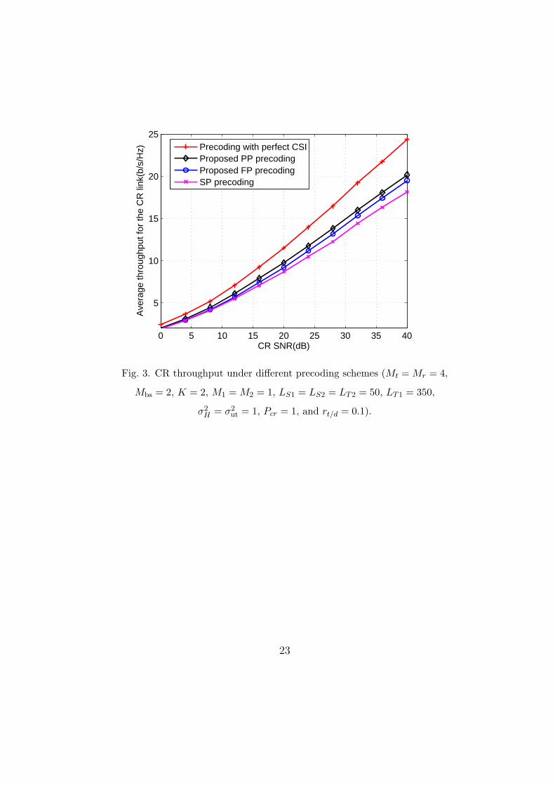
First, we evaluate the throughput of the CR system with the proposed
precoding schemes over different values of signal-to-noise ratios, SNR, σ2H/σ
2n.
In Fig. 3, the throughputs (average mutual information in (11)) of the two
proposed precoding schemes are compared with that of the SP precoding of
[17], [18] and the P-SVD precoding with perfect CSI of [14]. It can be seen
that the proposed FP/PP precoding schemes lead to higher CR throughput
14
than the SP precoding, and the throughput gain becomes larger as the SNR
increases.
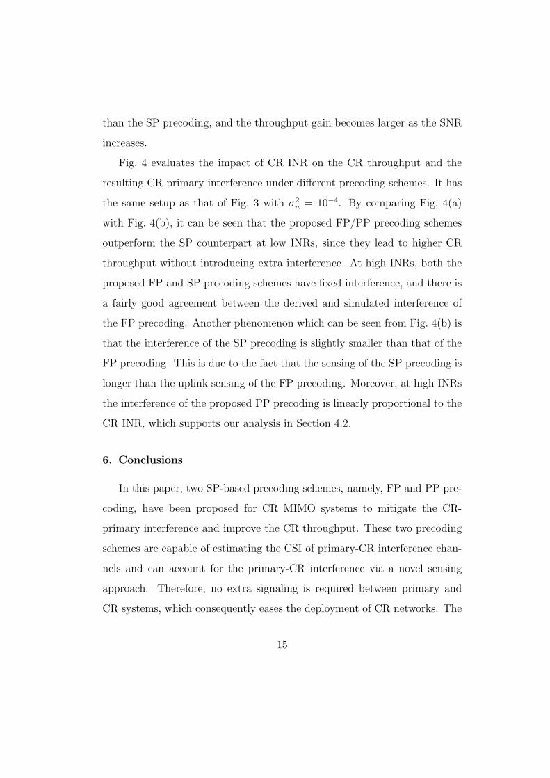
Fig. 4 evaluates the impact of CR INR on the CR throughput and the
resulting CR-primary interference under different precoding schemes. It has
the same setup as that of Fig. 3 with σ2n = 10−4. By comparing Fig. 4(a)
with Fig. 4(b), it can be seen that the proposed FP/PP precoding schemes
outperform the SP counterpart at low INRs, since they lead to higher CR
throughput without introducing extra interference. At high INRs, both the
proposed FP and SP precoding schemes have fixed interference, and there is
a fairly good agreement between the derived and simulated interference of
the FP precoding. Another phenomenon which can be seen from Fig. 4(b) is
that the interference of the SP precoding is slightly smaller than that of the
FP precoding. This is due to the fact that the sensing of the SP precoding is
longer than the uplink sensing of the FP precoding. Moreover, at high INRs
the interference of the proposed PP precoding is linearly proportional to the
CR INR, which supports our analysis in Section 4.2.
6. Conclusions
In this paper, two SP-based precoding schemes, namely, FP and PP pre-
coding, have been proposed for CR MIMO systems to mitigate the CR-
primary interference and improve the CR throughput. These two precoding
schemes are capable of estimating the CSI of primary-CR interference chan-
nels and can account for the primary-CR interference via a novel sensing
approach. Therefore, no extra signaling is required between primary and
CR systems, which consequently eases the deployment of CR networks. The
15

performance of the proposed precoding schemes has also been evaluated. It
has been demonstrated that the FP precoding can boost the CR throughput
without introducing extra CR-primary interference in the low INR regime.
The PP precoding can further improve the CR throughput if the primary
system can tolerate some extra interference.
Acknowledgments
The authors acknowledge the support from the RCUK for the UK-China Science
Bridges Project: R&D on (B)4G Wireless Mobile Communications. Z. Chen, C.-
X. Wang, and J. Thompson acknowledge the support from the Scottish Funding
Council for the Joint Research Institute in Signal and Image Processing between
the University of Edinburgh and Heriot-Watt University, as part of the Edinburgh
Research Partnership in Engineering and Mathematics (ERPem). Z. Chen and
S. A. Vorobyov acknowledge the support from the National Science and Engineer-
ing Research Council (NSERC) of Canada. F. Zhao acknowledges the support from
National Natural Science Foundation of China (NSFC) (Grant No.: 61172055). C.-
X. Wang and F. Zhao acknowledge the support of the Key Laboratory of Cognitive
Radio and Information Processing (Guilin University of Electronic Technology),
Ministry of Education, China (Grant No.: 2011KF01). X. Ge acknowledges the
support from the NSFC (Grant No.: 60872007), National 863 High Technology
Program of China (Grant No.: 2009AA01Z239), Hubei Provincial Science and
Technology Department (Grant No.: 2011BFA004), and the Ministry of Science
and Technology (MOST) of China, International Science and Technology Collab-
oration Program (Grant No.: 0903).
16

References
[1] S. Haykin, Cognitive radio: brain-empowered wireless communications,
IEEE J. Sel. Areas Commun. 2 (2005) 201–220.
[2] I. F. Akyildiz, W. Y. Lee, M. C. Vuran, S. Mohanty, NeXt genera-
tion/dynamic spectrum access/cognitive radio wireless networks: A sur-
vey, Computer Networks 13 (2006) 2127–2159.
[3] Q. Zhao, B. M. Sadler, A survey of dynamic spectrum access, IEEE
Signal Process. Mag. 3 (2007) 79–89.
[4] X. Hong, C.-X. Wang, H.-H. Chen, Y. Zhang, Secondary spectrum ac-
cess networks: recent developments on the spatial models, IEEE Veh.
Technol. Mag. 2 (2009) 36–43.
[5] C.-X. Wang, X. Hong, H.-H. Chen, J. Thompson, On capacity of cogni-
tive radio networks with average interference power constraints, IEEE
Trans. Wireless Commun. 4 (2009) 1620–1625.
[6] X. Hong, C.-X. Wang, M. Uysal, X. Ge, S. Ouyang, Capacity analysis
of hybrid cognitive radio networks with distributed VAAs, IEEE Trans.
Veh. Technol. 7 (2010) 3510–3523.
[7] X. Hong, Z. Chen, C.-X. Wang, S. A. Vorobyov, J. Thompson, Cognitive
radio networks: interference cancellation and management techniques,
IEEE Veh. Technol. Mag. 4 (2009) 76–84.
[8] J. Zhou, J. Thompson, Linear precoding for the downlink of multiple
17

input single output coexisting wireless systems, IET Commun. 6 (2008)
742–752.
[9] T. K. Phan, S. A. Vorobyov, N. D. Sidiropoulos, C. Tellambura, Spec-
trum sharing in wireless networks via QoS-aware secondary multicast
beamforming, IEEE Trans. Sig. Process. 6 (2009) 2323–2335.
[10] G. Zheng, K.-K. Wong, B. Ottersten, Robust cognitive beamforming
with bounded channel uncertainties, IEEE Trans. Sig. Process. 12 (2009)
4871–4881.
[11] L. Zhang, Y.-C. Liang, Y. Xin, H. V. Poor, Robust cognitive beam-
forming with partial channel state information, IEEE Trans. Wireless
Commun. 8 (2009) 4143–4153.
[12] G. Zheng, S. Ma, K.-K. Wong, T.-S. Ng, Robust beamforming in cogni-
tive radio, IEEE Trans. Wireless Commun.2 (2010) 570–576.
[13] L. Bixio, G. Oliveri, M. Ottonello, M. Raffetto, C. S. Regazzoni, Cog-
nitive radios with multiple antennas exploiting spatial opportunities,
IEEE Trans. Sig. Process. 8 (2010) 4453–4459.
[14] R. Zhang, Y.-C. Liang, Exploiting multi-antennas for opportunistic
spectrum sharing in cognitive radio networks, IEEE J. Sel. Topics Sig.
Process. 1 (2008) 88–102.
[15] G. Scutari, D. P. Palomar, S. Barbarossa, Cognitive MIMO radio: com-
petitive optimality design based on subspace projections, IEEE Sig. Pro-
cess. Mag. 6 (2008) 46–59.
18

[16] R. Roy, T. Kailath, ESPRIT-estimation of signal parameters via rota-
tional invariance techniques, IEEE Trans. on ASSP 7 (1989) 984–995.
[17] H. Yi, H. Hu, Y. Rui, K. Guo, J. Zhang, Null space-based precoding
scheme for secondary transmission in a cognitive radio MIMO system
using second-order statistics, in: Proc. IEEE ICC, 2009.
[18] R. Zhang, F. Gao, Y.-C. Liang, Cognitive beamforming made practical:
Effective interference channel and learning-throughput tradeoff, IEEE
Trans. Commun. 2 (2010) 706–718.
[19] H. Yi, Nullspace-based secondary joint transceiver scheme for cognitive
radio MIMO networks using second-order statistics, in: Proc. IEEE ICC,
2010.
[20] F. Gao, R. Zhang, Y.-C. Liang, X. Wang, Design of learning-based
MIMO cognitive radio systems, IEEE Trans. Veh. Technol. 4 (2010)
1707–1720.
[21] O. Somekh, O. Simeone, Y. Bar-Ness, W. Su, Detecting the number of
transmit antennas with unauthorized or cognitive receivers in MIMO
systems, in: Proc. IEEE MILCOM, 2007.
[22] Z. Chen, S. A. Vorobyov, C.-X. Wang, J. Thompson, Nash bargaining
over MIMO interference systems, in: Proc. IEEE ICC, 2009.
[23] D. W. Tufts, A. C. Kot, R. J. Vaccaro, The analysis of threshold behavior
of SVD-based algorithms, in: Proc. XXIst Annu. Asilomar Conf. Signals.
Syst. Comput., 1987.
19

[24] J. Thomas, L. Scharf, D. Tufts, The probability of a subspace swap in
the SVD, IEEE Trans. on Sig. Process. 3 (1995) 730–736.
[25] M. Hawkes, A. Nehorai, P. Stoica, Performance breakdown of subspace-
based methods: prediction and cure, in: Proc. IEEE ICASSP, 2001.
[26] F. Li, H. Liu, R. J. Vaccaro, Performance analysis for DOA estima-
tion algorithm: unification, simplification and observations, IEEE Trans.
Aerospace and Elec. Sys. 4 (1993) 1170–1184.
[27] M. Chiani, M. Z. Win, A. Zanella, R. K. Mallik, J. H. Winters, Bounds
and approximations for optimum combining of signals in the presence
of multiple co-channel interferers and thermal noise, IEEE Trans. Com-
mun. 2 (2003) 296–307.
20

Fig. 1. A CR MIMO transmitter-receiver pair coexists with a primary TDD
system.
21

Fig. 2. System diagram for the proposed precoding schemes.
22
0 5 10 15 20 25 30 35 40
5
10
15
20
25
CR SNR(dB)
Ave
rage
thro
ughp
ut fo
r th
e C
R li
nk(b
/s/H
z)
Precoding with perfect CSIProposed PP precodingProposed FP precodingSP precoding
Fig. 3. CR throughput under different precoding schemes (Mt = Mr = 4,
Mbs = 2, K = 2, M1 = M2 = 1, LS1 = LS2 = LT2 = 50, LT1 = 350,
σ2H = σ2
ut = 1, Pcr = 1, and rt/d = 0.1).
23

−40 −20 0 2017.5
18
18.5
19
19.5
20
20.5
21
21.5
22
CR INR (dB)
Ave
rage
CR
thro
ughp
ut (
b/s/
Hz)
(a)
Proposed FP precodingSP precodingProposed PP precoding
−40 −20 0 20
−45
−40
−35
−30
−25
−20
−15
−10
−5
0
CR INR (dB)
Ave
rage
inte
rfer
ence
at p
rimar
y us
er (
dBm
)
(b)
Proposed FP precodingSP precoding
Drived interference IhFP
Proposed PP precoding
Fig. 4. (a) CR throughput and (b) resulting interference of different precoding
schemes (Mt = Mr = 4, Mbs = 2, K = 2, M1 = M2 = 1,, LS = 100,
LS1 = LS2 = LT2 = 50, LT1 = 350, σ2H = 1, Pcr = 1, rt/d = 0.1, and σ2
n = 10−4).
24