interference of light - studymaterialcenter.in
TRANSCRIPT

JEE-Physics
E 1
NO
DE6\E:
\D
ata
\2014\Kota
\JE
E-A
dva
nced
\SM
P\Ph
y\U
nit N
o-1
1\W
ave
Optic
s\En
g\01_I
nte
rfer
ence
of L
ight
.p65
INTERFERENCE OF LIGHTLIGHT
The physical cause, with the help of which our eyes experience the sensation of vision, is known as light or theform of energy, which excites our retina and produce the sensation of vision, is known as light.
PROPERTIES OF VISIBLE LIGHT
• No material medium is required for the propagation of light energy i.e. it travels even in vacuum.
• Its velocity is constant in all inertial frames i.e. it is an absolute constant. It is independent of the relative velocitybetween source and the observer.
• Its velocity in vacuum is maximum whose value is 3 × 10⁸ m/s.
• It lies in the visible region of electromagnetic spectrum whose wavelength range is from 4000 Å to 8000 Å.
• Its energy is of the order of eV.
• It propagates in straight line.
• It exhibits the phenomena of reflection, refraction, interference, diffraction, polarisation and double refraction.
• It can emit electrons from metal surface i.e. it can produce photoelectric effect.
• It produces thermal effect and exerts pressure when incident upon a surface. It proves that light has momentumand energy.
• Its velocity is different in different media. In rarer medium it is more and in denser medium it is less.
• Light energy propagates via two processes.
(a) The particles of the medium carry energy from one point of the medium to another.
(b) The particles transmit energy to the neighbouring particles and in this way energy propagates in the formof a disturbance.
DIFFERENT THEORIES OF LIGHT
• Newton's corpuscular theory of light. • Hygen's wave theory of light.
• Maxwell's electromagnetic theory of light. • Plank's Quantum theory of light.
• De-Broglie's dual theory of light.
NEWTON'S CORPUSCULAR THEORY OF LIGHT
This theory was enuciated by Newton.
• Character ist ics of the theory
(i) Extremely minute, very light and elastic particles are being constantly emitted by all luminous bodies (lightsources) in all directions
(ii) These corpuscles travel with the speed of light..
(iii) When these corpuscles strike the retina of our eye then they produce the sensation of vision.
(iv) The velocity of these corpuscles in vacuum is 3 × 10⁸ m/s.
(v) The different colours of light are due to different size of these corpuscles.
(vi) The rest mass of these corpuscles is zero.
(vii) The velocity of these corpuscles in an isotropic medium is same in all directions but it changes with thechange of medium.
(viii) These corpuscles travel in straight lines.
(ix) These corpuscles are invisible.

JEE-Physics
2 E
NO
DE6\E:
\D
ata
\2014\Kota
\JE
E-A
dva
nced
\SM
P\Ph
y\U
nit N
o-1
1\W
ave
Optic
s\En
g\01_I
nte
rfer
ence
of L
ight
.p65
• The phenomena explained by this theory
(i) Reflection and refraction of light. (ii) Rectilinear propagation of light.
(iii) Existence of energy in light.
• The phenomena not explained by this theory
(i) Interference, diffraction, polarisation, double refraction and total internal reflection.
(ii) Velocity of light being greater in rarer medium than that in a denser medium.
(iii) Photoelectric effect and Crompton effect.
WAVE THEORY OF LIGHT
This theory was enunciated by Hygen in a hypothetical medium known as luminiferrous ether.
Ether is that imaginary medium which prevails in all space, in isotropic, perfectly elastic and massless.
The different colours of light are due to different wave lengths of these waves.
The velocity of light in a medium is constant but changes with change of medium.
This theory is valid for all types of waves.
(i) The locus of all ether particles vibrating in same phase is known as wavefront.
(ii) Light travels in the medium in the form of wavefront.
(iii) When light travels in a medium then the particles of medium start vibrating and consequently a disturbanceis created in the medium.
(iv) Every point on the wave front becomes the source of secondary wavelets. It emits secondary wavelets inall directions which travel with the speed of light (v),
The tangent plane to these secondary wavelets represents the new position of wave front.
1
2
3
4
A2
A1
A
B2
B1
4
3
2
1
A2 A1Aoriginalwavefront
newwavefront
secondarywavefront
Propagationof light-wave
S
B2 B1
B
(a)(b)
The phenomena explained by this theory
(i) Reflection, refraction, interference, diffraction, polarisation and double refraction.
(ii) Rectilinear propagation of light.
(iii) Velocity of light in rarer medium being grater than that in denser medium.
Phenomena not explained by this theory
(i) Photoelectric effect, Compton effect and Raman effect.
(ii) Backward propagation of light.

JEE-Physics
E 3
NO
DE6\E:
\D
ata
\2014\Kota
\JE
E-A
dva
nced
\SM
P\Ph
y\U
nit N
o-1
1\W
ave
Optic
s\En
g\01_I
nte
rfer
ence
of L
ight
.p65
WAVE FRONT, VARIOUS TYPES OF WAVE FRONT AND RAYS
• Wave f ron t
The locus of all the particles vibrating in the same phase is known as wavefront.
• Types of wavefront
The shape of wavefront depends upon the shape of the light source originating that wavefront. On the basis ofthere are three types of wavefront.
Comparative study of three types of wavefront
S.No. Wave f ron t Shape Diagram of Var iat ion of Var iat ion ofof l ight shape of amp l i t u de i ntens i t ys ou r c e wave f ron t with distance with distance
1. Spherical Point source Ad
1
or Ar
1
Ir
12
2. cylindrical Linear or slit
O
O'
1A
d or A
r
1I
r
1
3. Plane Extended large A = constant I = constant
source situated
at very large
distance
CHAR ACTERISTIC OF WAVEFRONT
(a) The phase difference between various particles on the wavefront is zero.
(b) These wavefronts travel with the speed of light in all directions in an isotropic medium.
(c) A point source of light always gives rise to a spherical wavefront in an isotropic medium.
(d) In an anisotropic medium it travels with different velocities in different directions.
(e) Normal to the wavefront represents a ray of light.
(f) It always travels in the forward direction of the medium.
RAY OF LIGHT
The path of the light energy from one point to another is known as a ray of light.
(a) A line drawn at right angles to the wavefront is defined as a ray of light, which is shown by arrows inprevious diagram of shape of wavefront.
(b) It represents the direction of propagation of light.

JEE-Physics
4 E
NO
DE6\E:
\D
ata
\2014\Kota
\JE
E-A
dva
nced
\SM
P\Ph
y\U
nit N
o-1
1\W
ave
Optic
s\En
g\01_I
nte
rfer
ence
of L
ight
.p65
INTERFERENCE OF LIGHT
When two light waves of same frequency with zero initial phase difference or constant phase difference superimpose
over each other, then the resultant amplitude (or intensity) in the region of superimposition is different from the
amplitude (or intensity) of individual waves.
This modification in intensity in the region of superposition is called interference.
( a ) Constructive interference
When resultant intensity is greater than the sum of two individual wave intensities [I > (I1 + I
2)], then the
interference is said to be constructive.
( b ) Destructive interference
When the resultant intensity is less than the sum of two individual wave intensities [I < (I1 + I
2)], then the
interference is said to destructive.
There is no violation of the law of conservation of energy in interference. Here, the energy from the points of
minimum energy is shifted to the points of maximum energy.
TYPES OF SOURCES
• Coherent source
Two sources are said to be coherent if they emit light waves of the same wavelength and start with same phase
or have a constant phase difference.
Note : Laser is a source of monochromatic light waves of high degree of coherence.
Main points :
1. They are obtained from the same single source.
2. Their state of polarization is the same
• Incoherent source
Two independent monochromatic sources, emit waves of same wavelength.
But the waves are not in phase. So they are incoherent. This is because, atoms
cannot emit light waves in same phase and these sources are said to be incoherent
sources. By using two independent laser beams it has been possible to record the
interference pattern.
METHOD FOR OBTAINING COHERENT SOURCE
• Division of wave front
In this method, the wavefront is divided into two or more parts by use of mirrors, lenses or prisms.
Example : Young's double slit experiment. Fresnel's Biprism and Lloyd's single mirror method.
S2
S1
P S1
S2
Lloyd's mirrorYDSEFresnel biprism
• Divis ion of ampli tude
The amplitude of incoming beam is divided into two or more parts by partial reflection or refraction. These
divided parts travel different paths and are finally brought together to produce interference.
Example : The brilliant colour seen in a thin film of transparent material like soap film, oil film, Michelson's
Interferro Meter, Newtons' ring etc.
JEE-Physics
E 5
NO
DE6\E:
\D
ata
\2014\Kota
\JE
E-A
dva
nced
\SM
P\Ph
y\U
nit N
o-1
1\W
ave
Optic
s\En
g\01_I
nte
rfer
ence
of L
ight
.p65
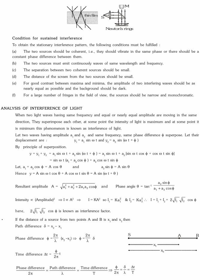
thin film
S
M
Newton's rings
Condition for sustained interference
To obtain the stationary interference pattern, the following conditions must be fulfilled :
(a) The two sources should be coherent, i.e., they should vibrate in the same phase or there should be a
constant phase difference between them.
(b) The two sources must emit continuously waves of same wavelength and frequency.
(c) The separation between two coherent sources should be small.
(d) The distance of the screen from the two sources should be small.
(e) For good contrast between maxima and minima, the amplitude of two interfering waves should be as
nearly equal as possible and the background should be dark.
(f) For a large number of fringes in the field of view, the sources should be narrow and monochromatic.
ANALYSIS OF INTERFERENCE OF LIGHT
When two light waves having same frequency and equal or nearly equal amplitude are moving in the same
direction, They superimpose each other, at some point the intensity of light is maximum and at some point it
is minimum this phenomenon is known as interference of light.
Let two waves having amplitude a1 and a
2 and same frequency, same phase difference superpose. Let their
displacement are : y1 = a
1 sin t and y
2 = a
2 sin ( t + )
By principle of superposition.
y = y1 + y
2 = a
1 sin t + a
2 sin ( t + ) = a
1 sin t + a
2 [sin t cos + cos t sin ]
= sin t (a1 + a
2 cos ) + a
2 cos t sin
Let, a1 + a
2 cos = A cos and a
2 sin = A sin
Hence y = A sin t cos + A cos t sin = A sin (t + )
Resultant amplitude A = 2 21 2 1 2a a 2a a cos and Phase angle = tan–1
2
1 2
a sin
a a cos
Intensity (Amplitude)2 I A2 I = KA2 so I1 = 2
1Ka & I2 = 2
2Ka I = I1 + I
2 + 1 22 I I cos
here, 1 22 I I cos is known as interference factor..
• If the distance of a source from two points A and B is x1 and x
2 then
Path difference = x2 – x
1
Phase difference =2
(x
2 –x
1) =
2
S A B
x2
x1
Time difference t = t2
Phase difference Path difference Time difference
2 T
t
2 T

JEE-Physics
6 E
NO
DE6\E:
\D
ata
\2014\Kota
\JE
E-A
dva
nced
\SM
P\Ph
y\U
nit N
o-1
1\W
ave
Optic
s\En
g\01_I
nte
rfer
ence
of L
ight
.p65
TYPES OF INTERFERENCE
Constructive Interference
When both waves are in same phase. So phase difference is an even multiple of = 2 n n = 0,1,2 ...
• When path difference is an even multiple of
2
2
2n
2
= 2n
2
= n(where n = 0,1,2...)
• When time difference is an even multiple of T
2 t = 2n
T
2
• In this condition the resultant amplitude and Intensity will be maximum.
Amax
= (a1 + a
2) I
max = I
1 + I
2 + 1 22 I I = 2
1 2( I I )
Destructive Interference
When both the waves are in opposite phase. So phase difference is an odd multiple of .
= (2 n–1) n = 1, 2 ...
• When path difference is an odd multiple of 2
, = ( 2n –1)
2
, n = 1, 2 ...
• When time difference is an odd multiple of T
2, t = (2n–1)
T
2, ( n=1,2...)
In this condition the resultant amplitude and intensity of wave will be minimum.
Amin
= (a1
– a2)
Imin
= 21 2( I I )
GOLDEN KEY POINTS
• Interference follows law of conservation of energy.
• Average Intensity Iav
= 2 2max min
1 2 1 2
I II I a a
2
• Intensity width of slit (amplitude)2 I w a2
21 1 1
22 2 2
I w a
I w a
•
2 221 2max max1 2
min 1 2 min1 2
I II aa a
I a a aI I
• Fringe visibility V = max min
max min
I I100%
I I
when Imin
= 0 then fringe visibility is maximum
i.e. when both slits are of equal width the fringe visibility is the best and equal to 100%.

JEE-Physics
E 7
NO
DE6\E:
\D
ata
\2014\Kota
\JE
E-A
dva
nced
\SM
P\Ph
y\U
nit N
o-1
1\W
ave
Optic
s\En
g\01_I
nte
rfer
ence
of L
ight
.p65
Examp l e
If two waves represented by y1 = 4 sin t and y
2 = 3 sin ( t )
3
interfere at a point. Find out the amplitude of
the resulting wave.
So lu t i on
Resultant amplitude A = 2 21 2 1 2a a 2a a cos =
22(4) 3 2.(4)(3) cos3
A ~ 6
Examp l e
Two beams of light having intensities I and 4I interferer to produce a fringe pattern on a screen. The phase
difference between the beam is 2
at point A and 2 at point B. Then find out the difference between the
resultant intensities at A and B.
So lu t i on
Resultant intensity I = I
1 + I
2 + 1 22 I I cos
Resultant intensity at point A is IA
= I + 4I + 2 I 4I cos 5I2
Resultant intensity at point B, IB
= I + 4I
+ 2 I 4I cos 2 = 9I (cos 2= 1) I
B – I
A = 9 I – 5 I 4 I
Ex amp l e
In interference pattern, if the slit widths are in the ratio 1:9. Then find out the ratio of minimum and maximumintensity.
So lu t i on
Slit width ratio
1
2
w 1
w 9
21 1 1
22 2 2
I w a 1
I w 9a
1
2
a
a = 1
33a
1 = a
2
2min 1 2
2max 1 2
I (a a )
I (a a )
=
21 1
21 1
(a 3a )
(a 3a )
=
4
16 = 1 : 4
Examp l e
The intensity variation in the interference pattern obtained with the help of two coherent source is 5% of theaverage intensity. Find out the ratio of intensities of two sources.
So lu t i on
max
min
I 105 21
I 95 19
21 2
21 2
(a a ) 21
19(a a )
1 2
1 2
a a 21
a a 19
= 1.05 a
1 + a
2 = 1.05 a
1 – 1.05 a
2
0.05 a1 = 2.05 a
2
1
2
a 2.05 41
a 0.05 1
21 1
2 2
I a 1680
I a 1
Examp l e
Waves emitted by two identical sources produces intensity of K unit at a point on screen where path difference
between these waves is , calculate the intensity at that point on screen at which path difference is 4
.
So lu t i on
1
2
22
and
2=
2
4 2
I
1 = I
0 + I
0 + 0 0 02 I I cos 2 4 I
and I2 = I
0 + I
0 + 0 0 0
cos22 I I 2 I
2
01
2 0
4II2
I 2I I
2 =
1I K
2 2 unit [ I
1 = K unit]

JEE-Physics
8 E
NO
DE6\E:
\D
ata
\2014\Kota
\JE
E-A
dva
nced
\SM
P\Ph
y\U
nit N
o-1
1\W
ave
Optic
s\En
g\01_I
nte
rfer
ence
of L
ight
.p65
YOUNG'S DOUBLE SLIT EXPERIMENT (YDSE)
According to Huygen, light is a wave. It is proved experimentally by YDSE.
S is a narrow slit illuminated by a monochromatic source of light sends wave fronts in all directions. Slits S1 and
S2
become the source of secondary wavelets which are in phase and of same frequency. These waves aresuperimposed on each other gave rise to interference. Alternate dark and bright bands are obtained on ascreen (called interference fringes) placed certain distance from the plane of slit S
1 and S
2 . Central fringe is
always bright (due to path from S1O and S
2O
centre is equal) called central maxima.
sodium lamp
S
S1
S2
screen
O
d
S
S1
S2
z=0
y
x
D
Energy is conserved in interference. This indicated that energy is redistributed from destructive interference
region to the constructive interference region .
• If one of the two slit is closed. The interference pattern disappears. It shows that two coherent sources are
required to produce interference pattern.
• If white light is used as parent source, then the fringes will be coloured and of unequal width.
(i) Central fringe will be white.
(ii) As the wave length of violet colour is least, so fringe nearest to either side of the central white fringe is violet
and the fringe farthest from the central white fringe is red.
CONDITION FOR BRIGHT AND DARK FRINGES
Bright Fr inge
D = distance between slit and screen, d = distance between slit S1 and S
2
Bright fringe occurs due to constructive interference.
For constructive interference path difference should be even multiple of 2
Path difference = PS2 – PS
1 = S
2 L (2n )
2
In PCO tan= nx
D; In S
1S
2L sin=
d
S2
S1
DB
C
A
xn
dO
P
L= n for bright fringes
If is small then tan~ sin nx
D d
The distance of nth bright fringe from the central bright fringe xn =
Dn
d

JEE-Physics
E 9
NO
DE6\E:
\D
ata
\2014\Kota
\JE
E-A
dva
nced
\SM
P\Ph
y\U
nit N
o-1
1\W
ave
Optic
s\En
g\01_I
nte
rfer
ence
of L
ight
.p65
Dark Fringe
Dark fringe occurs due to destructive interference.
For destructive interference path difference should be odd multiple of 2
.
Path difference = (2m –1) 2
The distance of the mth dark fringe from the central bright fringe xm
= (2m 1)D
2d
FRINGE WIDTH
The distance between two successive bright or
second dark
first bright
first dark
centre bright
first dark
first bright
second dark
second bright
2 x=
0ce
ntra
l frin
ge
dark fringe is known as fringe width.
n 1 nx x = (n 1)D nD
d d
(n+1)
dark fringe
th
ndark fringe
th
xn+1
xnFringe Width =
D
d
ANGULAR FRINGE WIDTH
S1
S2
angular width
fringewidth
D
Angular Fringe WidthD
,
d
D d
• The distance of nth bright fringe from the central bright fringe n
n Dx n
d
• The distance between n1 and n
2 bright fringe
2 1n n 2 1 2 1
D Dx x n n (n n )
d d
• The distance of mth dark fringe from central fringe m
(2m 1)D (2m 1)x
2d 2
• The distance of nth bright fringe from mth dark fringe n m
D (2m 1)D (2m 1)x x n n
d 2d 2
n m
(2m 1)x x n
2

JEE-Physics
10 E
NO
DE6\E:
\D
ata
\2014\Kota
\JE
E-A
dva
nced
\SM
P\Ph
y\U
nit N
o-1
1\W
ave
Optic
s\En
g\01_I
nte
rfer
ence
of L
ight
.p65
GOLDEN KEY POINTS
• If the whole apparatus is immersed in a liquid of refractive index , then wavelength of light
' =
since >1 so '< wavelength will decrease. Hence fringe width ( ) will decrease
fringe width in liquid ' = angular width will also decrease.
• With increase in distance between slit and screen D, angular width of maxima does not change, fringe width increase linearly with D but the intensity of fringes decreases.
• If an additional phase difference of is created in one of the wave then the central fringe become dark.
• When wavelength is used to obtain a fringe n
1 . At the same point wavelength
2is required to obtain a
fringe n2
then n1
1= n
2
2
• When waves from two coherent sources S1 and S2 interfere in space the shape of the fringe is hyperbolic withfoci at S1 and S2 .
Ex amp l e
Laser light of wavelength 630 nm incident on a pair of slits produces an interference pattern in which the brightfringes are separated by 8.1 mm. A second light produces an interference pattern in which the fringesare separated by 7.2 mm. Calculate the wavelength of the second light.
So lu t i on
Fringe separation is given by = D
d
i.e. 2 2
1 1
2 =
21
1
= 7.2
6308.1
= 560 nm
Examp l e
A double slit is illuminated by light of wave length 6000Å. The slit are 0.1 cm apart and the screen is placed onemetre away. Calculate :
(i) The angular position of the 10th maximum in radian and
(ii) Separation of the two adjacent minima.
So lu t i on
(i) = 6000 Å = 6 × 10⁻⁷ m, d = 0.1 cm = 1 × 10⁻³ m, D = 1m, n = 10
Angular position n =
n
d
=
73
3
10 6 106 10 rad.
10
(ii) Separation between two adjacent minima = fringe width
= 7
3
D 6 10 1
d 1 10
= 6 × 10– 4 m= 0.6 mm
Examp l e
In Young's double slit experiment the fringes are formed at a distance of 1m from double slit of separation 0.12mm. Calculate
(i) The distance of 3rd dark band from the centre of the screen.
(ii) The distance of 3rd bright band from the centre of the screen, given = 6000Å
So lu t i on
(i) For mth dark fringe m
D'x (2m 1)2d
given, D = 1m = 100 cm, d = 0.12 mm = 0.012 cm
7
3
(2 3 1) 100 6 10'x2 0.012
= 1.25 cm [m = 3 and = 6 × 10⁻⁷ m]
(ii) For nth bright fringe xn =
nD
d
7
3
3 100 6 10x
0.012
= 1.5 × 10⁻² m = 1.5 cm [n = 3]
JEE-Physics
E 11
NO
DE6\E:
\D
ata
\2014\Kota
\JE
E-A
dva
nced
\SM
P\Ph
y\U
nit N
o-1
1\W
ave
Optic
s\En
g\01_I
nte
rfer
ence
of L
ight
.p65
Examp l e
In Young's double slit experiment the two slits are illuminated by light of wavelength 5890Å and the distancebetween the fringes obtained on the screen is 0.2°. The whole apparatus is immersed in water, then find out
angular fringe width, (refractive index of water = 4
3).
So lu t i on
air
= d
air = 0.2° w w
air air
w air
w air
.
=
0.2 3
4
= 0.15
Examp l e
The path difference between two interfering waves at a point on screen is 171.5 times the wavelength. If thepath difference is 0.01029 cm. Find the wavelength.
So lu t i on
Path difference = 171.5 343
2 = odd multiple of half wavelength . It means dark finge is observed
According to question 343
0.010292
50.01029 2
6 10 cm343
= 6000 Å
Examp l e
In young's double slit interference experiment, the distance between two sources is 0.1/mm. The distance ofthe screen from the source is 25 cm. Wavelength of light used is 5000Å. Then what is the angular position of thefirst dark fringe ?
So lu t i on
The angular position D d
D( )
d
The first dark fringe will be at half the fringe width from the mid
point of central maximum. Thus the angular position of first dark fringe will be-
1
2 2 d
10
–3
1 5000 18010
2 .1 10
= 0.45°.
FRESNEL'S BIPRISM
It is an optical device to obtain two coherent sources by refraction of light. It is prepared by rubbing an
optically pure glass plate slightly on two sides so that each angle of prism is generally 1
2
or 1°. The fringes
of equal width are observed in the limited region MN due to superposition.
D
b
distance between source and screen
a
d
dist
ance
bet
wee
nso
urce
S1
S2
S
prismvirtualsource
overlapping
M
N
P

JEE-Physics
12 E
NO
DE6\E:
\D
ata
\2014\Kota
\JE
E-A
dva
nced
\SM
P\Ph
y\U
nit N
o-1
1\W
ave
Optic
s\En
g\01_I
nte
rfer
ence
of L
ight
.p65
Distance between source and biprism = a
Distance between biprism and eye piece (screen) = b
The distance between source and screen D = a + b
d2
a
S
S1 PRefracting angle = , refractive index of the material of prism =
The distance between two coherent source = d
From SS1P
d / 2tan
a for very-very small hence tan = so
d
2a d = 2a
For prism = ( d = 2a(, Fringe width D
d
(a b)
2a( 1)
• To calculate the value of d by displacement method
In this method a convex lens is placed between prism and screen. The lens is adjusted in two position L1 and L
2
and image is obtained on screen. Let d1 an d
2 be the real image in these two cases.
The distance d between the virtual source 1 2d d d Fringe width 1 2
(a b)
d d
S2
S
S1
d d2 d1
S'2
S"2
S"1
S1
displacement method
L1L2
GOLDEN KEY POINTS
• If the fresnel biprism experiment is performed in water instead of air then
(i) Fringe width in water increases g
w air
g w
1
w = 3
air g w
3 4,
2 3
(ii) Separation between the two virtual sources decreases.
(but in Young's double slit experiment it does not change.)
dair
= 2 a (g –1) d
w = 2 a (
w
g –1) d
w = 2 a
g
w
1
w
air
d
d =
g
w
g
1
1
=
3 / 21
14 / 3
3 / 2 1 4
dw
= 1
4 d
air
• If we use white light instead of monochromatic light then coloured fringes of different width are obtained.Central fringe is white.
• With the help of this experiment the wavelength of monochromatic light, thickness of thin films and theirrefractive index and distance between apparent coherent sources can be determined.

JEE-Physics
E 13
NO
DE6\E:
\D
ata
\2014\Kota
\JE
E-A
dva
nced
\SM
P\Ph
y\U
nit N
o-1
1\W
ave
Optic
s\En
g\01_I
nte
rfer
ence
of L
ight
.p65
Examp l e
Fringes are obtained with the help of a biprism in the focal plane of an eyepiece distant 1m from the slit. A
convex lens produces images of the slit in two position between biprism and eyepiece. The distances between
two images of the slit in two positions are 4.05 × 10⁻³ m and 2.9 × 10⁻³ m respectively. Calculate the distance
between the slits.
So lu t i on
d = 1 2d d = 3 34.05 10 2.9 10 = 3.43 × 10⁻³ m
Examp l e
In fresnel's biprism experiment a mica sheet of refractive index 1.5 and thickness 6 × 10⁻⁶ m is placed in the
path of one of interfering beams as a result of which the central fringe gets shifted through five fringe widths.
Then calculate the wavelength of light.
So lu t i on
x = ( 1)t
=
(1.5 1)t
but, t = 5 5=
0.5 t
=
t
10=
66 10
10
= 6000Å
Examp l e
A whole biprism experiment is immersed in water. If the fringe width in air is a and refractive index of biprism
material and water are 1.5 and 1.33 respectively. Find the value of the fringe width.
So lu t i on
g
w a a
g w
311 2 3
3 4
2 2
Examp l e
In fresnel's biprism experiment the distance between the source and the screen is 1m and that between the
source and biprism is 10 cm. The wavelength of light used is 6000Å. The fringe width obtained is 0.03 cm and
the refracting angle of biprism is 1°. Then calculate the refractive index of the material of biprism.
So lu t i on
=D
2a( 1)
( –1) =
D
2a
=7
4
1 6 10 180
2 0.1 3 10 3.14
(–1) = 0.573 = 1.573
THICKNESS OF THIN FILMS
When a glass plate of thickness t and refractive index is placed in front of the slit in YDSE then the central
fringe shifts towards that side in which glass plate is placed because extra path difference is introduced by the
glass plate. In the path S
1P distance travelled by wave in air = S
1 P – t
t
S2
S1
D
O
x
d
Pshifted central
fringe
path difference ( 1)t
central fringe

JEE-Physics
14 E
NO
DE6\E:
\D
ata
\2014\Kota
\JE
E-A
dva
nced
\SM
P\Ph
y\U
nit N
o-1
1\W
ave
Optic
s\En
g\01_I
nte
rfer
ence
of L
ight
.p65
Distance travelled by wave in the sheet = t
Time taken by light to reach up to point P will be same from S1 and S
2
2 1S P S P t t
c c c /
2 1S P S P ( 1)t
c c
S
2 P = S
1 P + ( –1)t S
2 P – S
1 P = ( –1)t
Path difference = ( –1)tPhase difference = 2
( 1)t
Distance of shifted fringe from central fringe x = D( 1)t
d
xd( 1)t
D
x = ( 1)t
and =
D
d
Number of fringes displaced =
( 1)t
Examp l e
When a mica sheet of thickness 7 microns and = 1.6 is placed in the path of one of interfering
beams in the biprism experiment then the central fringe gets at the position of seventh bright fringe.
What is the wavelength of light used ?
So lu t i on
( 1)t
n
6(1.6 1) 7 10
7
= 6 × 10⁻⁷ meter
GOLDEN KEY POINTS
• If a glass plate of refractive index 1 and
2 having same thickness t is placed in the path of ray coming from S
1
and S2
then path difference x = 1 2
D( )t
d
• Distance of displaced fringe from central fringe x = 1 2( )t
D
d
COLOURS IN THIN FILMS
When white light is made incident on a thin film (like oil film on the surface of water or a soap bubble) Then
interference takes place between the waves reflected from its two surfaces and waves refracted through it.
The intensity becomes maximum and minimum as a result of interference and colours are seen.
(i) The source of light must be an extended source
(ii) The colours obtained in reflected and transmitted light are mutually complementary.
(iii) The colours obtains in thin films are due to interference whereas those obtained in prism are due to
dispersion.
INTERFERENCE DUE TO THIN FILMS
Consider a thin transparent film of thickness t and refractive index . Let a ray of light AB incident on the film
at B. At B, a part of light is reflected along BR1, and a part of light refracted along BC. At C a part of light is
reflected along CD and a part of light transmitted along CT1. At D, a part of light is refracted along DR
2 and
a part of light is reflected along DE. Thus interference in this film takes place due to reflected light in between
BR1 and DR
2 also in transmitted light in between CT
1 and ET
2.

JEE-Physics
E 15
NO
DE6\E:
\D
ata
\2014\Kota
\JE
E-A
dva
nced
\SM
P\Ph
y\U
nit N
o-1
1\W
ave
Optic
s\En
g\01_I
nte
rfer
ence
of L
ight
.p65
R1 R2 R3
T1 T2
AN
B
C E
D
t
ii
r
r r
i i
• Reflected System
The path difference between BR1 and DR
2 is x = 2t cos r due to reflection from the surface of denser medium
involves an additional phase difference of or path difference . Therefore the exact path difference between
BR1
and DR2
is. x' = 2 t cos r – maximum or constructive Interference occurs when path difference
between the light waves is n2 t cos r – = n2 t cos r = n+
So the film will appear bright if 2 t cos r = (2n + 1) (n = 0, 1, 2, 3 .....)
• For minima or destructive interference :
When path difference is odd multiple of 2
2 t cos r –
2
= (2n – 1)
2
So the film will appear dark if 2 t cos r = n
• For transmitted system
Since No additional path difference between transmitted rays C T1
and E T2
.
So the net path difference between them is x = 2 t cos r
For maxima 2 t cos r = n , n = 0, 1, 2.............
Minima 2 t cos r = (2n +1)2
n = 0, 1, 2.............s
USES OF INTERFERENCE EFFECT
Thin layer of oil on water and soap bubbles show different colours due to interference of waves reflected from two
surfaces of their films. Similarly when a lens of large radius of curvature is placed on a plane glass plate, an air film
exist between the plate and the lens. If sodium light is put on this film, concentric bright and dark interference rings
are formed. These rings are called as Newton's rings.
Uses :
• Used to determine the wavelength of light precisely.
• Used to determine refractive index or thickness of transparent sheet.
• Used to test the flatness of plane surfaces. These surfaces are knows as optically plane surfaces.
• Used to calibrate meters in terms of wavelength of light.
• Used to design optical filter which allows a narrow band of wavelength to pass through it.
• Used in holography to produce 3-D images.

JEE-Physics
16 E
NO
DE6\E:
\D
ata
\2014\Kota
\JE
E-A
dva
nced
\SM
P\Ph
y\U
nit N
o-1
1\W
ave
Optic
s\En
g\01_I
nte
rfer
ence
of L
ight
.p65
Examp l e
Light of wavelength 6000Å is incident on a thin glass plate of refractive index 1.5 such that angle of refractioninto the plate is 60°. Calculate the smallest thickness of plate which will make it appear dark by reflection.
So lu t i on
2t cos r = n t = n
2 cos r
=
71 6 10
2 1.5 cos 60
=
76 10
1.5
= 4 × 10⁻⁷ m
Examp l e
Light is incident on a glass plate (= 1.5) such that angle of refraction is 60°. Dark band is observed correspondingto the wavelength of 6000Å . If the thickness of glass plate is 1.2 × 10⁻³ mm. calculate the order of theinterference band.
So lu t i on
= 1.5, r = 60°, =6000Å = 6 × 10⁻⁷ m t = 1.2 × 10–3 = 1.2 × 10⁻⁶ m
For dark band in the reflected light 2 t cos r n
n = 2 t cos r
=
6
7
2 1.5 1.2 10 cos 60
6 10
=
6
7
12 1.5 1.2 10
26 10
= 3
Thus third dark band is observed.

JEE-Physics
E 17
NO
DE6\E:
\D
ata
\2014\Kota
\JE
E-A
dva
nced
\SM
P\Ph
y\U
nit N
o-1
1\W
ave
Optic
s\En
g\01_I
nte
rfer
ence
of L
ight
.p65
SOME WORKED OUT EXAMPLES
Examp le#1
State two conditions to obtain sustained interference of light. In Young's double slit experiment, using light ofwavelength 400 nm, interference fringes of width 'X' are obtained. The wavelength of light is increased to 600nm and the separation between the slits is halved. If one wants the observed fringe width on the screen to be thesame in the two cases, find the ratio of the distance between the screen and the plane of the slits in the twoarrangements.
So l . Conditions for sustained interference of light
(i) Sources should be coherent. (ii) There should be point sources
fringe width
D
d Here,
1
1 1
1
D
d and
2
2 2
2
D
d
As 1 1
1
2 2
2
D
d
D
d
D
D
d
d1
2
2 1
1 2
600
400
1
1 2
6
2
3
1
Examp le#2
Young's double slit experiment is carried out using microwaves of wavelength = 3 cm. Distance in betweenplane of slits and the screen is D = 100 cm. and distance in between the slits is 5 cm. Find
(a) the number of maximas and (b) their positions on the screen
So l . (a) The maximum path difference that can be produced = distance between the sources or 5 cm. Thus,in this case we can have only three maximas, one central maxima and two on its either side for a path differenceof or 3 cm.
(b) For maximum intensity at P, S2P – S
1P = ( / )y d D 2 2 2 – ( / )y d D 2 2 2 =
O
substiuting d = 5 cm, D = 100 cm and = 3cm we get y = 75 cm
Thus, the three maximas will be at y = 0 and y = 75 cm
Examp le#3
A beam of light consisting of two wavelengths 6500 Å and 5200 Å is used to obtain interference fringes in
a young's double slit experiment. The distance between the slits is 2 mm and the distance between the plane
of the slits and screen is 120 cm.
(a) Find the distance of the third bright fringe on the screen from the central maxima for the wavelength 6500
Å.
(b) What is the least distance from the central maxima where the bright fringes due to both the wave-lengths
coincide ?

JEE-Physics
18 E
NO
DE6\E:
\D
ata
\2014\Kota
\JE
E-A
dva
nced
\SM
P\Ph
y\U
nit N
o-1
1\W
ave
Optic
s\En
g\01_I
nte
rfer
ence
of L
ight
.p65
So l . (a) Distance of third bright fringe from centre of screen
xnD
d3
2 10
3
3 120 10 6500 10
2 10
= 1.17 × 10⁻³ m = 1.17 mm
(b) When bright fringes coincide to each other then n11 = n22 n
n
Å
Å
1
2
2
1
5200
6500
4
5
for minimum value of n1 & n2 n1 = 4, n2 = 5
So xn D
d 1 1 =
4 6500 10 120 10
2 10
10 2
3
= 0.156 × 10⁻² m = 0.156 cm
Examp le#4
An electromagnetic wave of wavelength 0 (in vacuum) passes from P towards Q crossing three different media
of refractive index , 2 and 3 respectively as shown in figure. P and
Q be the phase of the wave at points P
and Q. Find the phase difference Q –
P. [Take : =1]
2.25 0 3.50 3 0
µ 2µ 3µ
P Q
(A) 0 (B) 4
(C)
2
(D)
So lu t i on Ans. (C)
Optical path difference between (OPD) P & Q
(O.P.D.) = 2.25 0 ×1 + (3.5
0) × 2 + 3
0 × 3 = 18.25
0 and phase difference
0
2x
2
Examp le#5
Two slits separated by a distance of 1 mm are illuminated with red light of wavelength 6.5×10⁻⁷ m. The interferencefringes are observed on a screen placed 1m from the slits. The distance between the third dark fringe and thefifth bright fringe is equal to
(A) 0.65 mm (B) 1.625 mm (C) 3.25 mm (D) 0.975 mm
S o l u t i o n Ans . (B )
Distance between third dark fringe and the fifth bright fringe
=
7
3
D 6.5 10 12.5 2.5 2.5 1.625 mm
d 10
Examp le#6In the figure shown if a parallel beam of white light is incident on the plane of the slits then the distanceof the only white spot on the screen from O is :[ assume d << D , << d ]
2d/3dO
D
(A) 0 (B) d/2 (C) d/3 (D) d/6

JEE-Physics
E 19
NO
DE6\E:
\D
ata
\2014\Kota
\JE
E-A
dva
nced
\SM
P\Ph
y\U
nit N
o-1
1\W
ave
Optic
s\En
g\01_I
nte
rfer
ence
of L
ight
.p65
S o l u t i o n Ans. (D)
White spot will be at the symmetrical point w.r.t. slits . Its distance from O will be ,(2d/3) (d/2) = d/6 .
Examp le#7
In a Young’s double slit experiment the slits S1 & S
2 are illuminated by a parallel beam of light of wavelength
4000 Å, from the medium of refractive index n1 = 1.2. A thin film of thickness 1.2m and refractive index n
= 1.5 is placed infront of S1 perpendicular to path of light. The refractive index of medium between plane of
slits & screen is n2 = 1.4. If the light coming from the film and S
1 & S
2 have equal intensities I then intensity at
geometrical centre of the screen O is
n1 n2
screen
S1
S2
o
(A) 0 (B) 2I (C) 4I (D) None of these
So lu t i on Ans. (B)
Path difference at O : (rel
1) t =2
n1
n
t
Phase difference at O: t2
n1
n
2
2
where n
1
1=n
2
2
Phase difference=2
Resultant intensity = 2I
Examp le#8
In a YDSE experiment two slits S1 and S
2 have separation of d = 2 mm. The distance of the screen is D =
8
5
m. Source S starts moving from a very large distance towards S2 perpendicular to S
1S
2 as shown in figure. The
wavelength of monochromatic light is 500 nm. The number of maximas observed on the screen at point P as
the source moves towards S2 is
S1
S PS2
(A) 4001 (B) 3999 (C) 3998 (D) 4000
So lu t i on Ans. (D)
S1P–S
2P =
2d
2D=
3 32 10 2 0
82
5
= 5
2 500nm
So when S is at there is Ist minima and when S is at S2 there is last minima because d/=4000
So the number of minima's will be 4001 and number of maxima's will be 4000.
JEE-Physics
20 E
NO
DE6\E:
\D
ata
\2014\Kota
\JE
E-A
dva
nced
\SM
P\Ph
y\U
nit N
o-1
1\W
ave
Optic
s\En
g\01_I
nte
rfer
ence
of L
ight
.p65
Examp le#9Consider the optical system shown in figure. The point source of light S is having wavelength equals to .Thelight is reaching screen only after reflection. For point P to be 2nd maxima, the value of would be (D>>dand d>> )
S
P
(A) 212d
D(B)
26d
D(C)
23d
D(D)
224d
D
So lu t i on Ans. (A)
3d
S
P
Centralmaxima
S1
S2
6d
2d
O
At P, 8d 3d
xD
; For 2nd maxima, x =2
224d2
D
212d
D
Example#10 to12In the figure shown, S is a point monochromatic light source of frequency 6 × 10¹⁴ Hz.M is a concave mirrorof radius of curvature 20 cm and L is a thin converging lens of focal length 3.75 cm. AB is the principal axisof M and L.
22.5cm
B1mm
30cmS80cm
A
Screen L
M
Light reflected from the mirror and refracted from the lens in succession reaches the screen. An interferencepattern is obtained on the screen by this arrangement.
1 0 . Distance between two coherent sources which makes interference pattern on the screen is-
(A) 1 mm (B) 0.5 mm (C) 1.5 mm (D) 0.25 mm
1 1 . Fringe width is-
(A) 1mm (B) 0.5 mm (C) 1.5 mm (D) 0.25 mm

JEE-Physics
E 21
NO
DE6\E:
\D
ata
\2014\Kota
\JE
E-A
dva
nced
\SM
P\Ph
y\U
nit N
o-1
1\W
ave
Optic
s\En
g\01_I
nte
rfer
ence
of L
ight
.p65
1 2 . If the lens is replaced by another converging lens of focal length 10
3cm and the lens is shifted towards
right by 2.5 cm then-
(A) Fringe width remains same (B) Intensity of pattern will remain same
(C) Fringe width will change (D) No interference pattern will form.
S o l u t i o n
1 0 . Ans. (B)
Wave length of light 7c
5 10 mf
I2
I1
SImage formed by M :
1 1 1
v 30 10
v = –15 cm also M = –v 15 1
u 30 2
.
This will be located at 15 cm left of M and 0.5 mm above the line AB.
This will act as an object for the lens L.
Now for the lens u = –7.5cm and m = v 7.5
1u 7.5
So it will be at 7.5 cm to the left of L and 0.5 mm below line AB. See the ray diagram. Second image I2
and source S will act as two slits (as in YDSE) to produce the interference pattern . Distance between
them = 0.5 mm (= d)
1 1 . Ans. (B)
=
7 2
3
5 10 50 10
0.5 10
= 5 10 -4 m = 0.5 mm
1 2 . Ans. (D)
Image formed by the combination is I2 at 5cm
15cm
0.5cmI1
S1
v–
1
5
3
10 v
=
10 cm . It will coincide with S
so no interference pattern on the screen .
Examp l e#13
Statement–1: In Young's double slit experiment the two slits are at distance d apart. Interference pattern is
observed on a screen at distance D from the slits. At a point on the screen when it is directly opposite to one
of the slits, a dark fringe is observed. Then, the wavelength of wave is proportional to square of distance of two
slits.
a n d
Statement–2 : In Young's double slit experiment, for identical slits, the intensity of a dark fringe is zero.
(A) Statement–1 is True, Statement–2 is True ; Statement–2 is a correct explanat ion for Statement–1
(B) Statement–1 is True, Statement–2 is True ; Statement–2 is not a correct explanation for Statement–1
(C) Statement–1 is True, Statement–2 is False.
(D) Statement–1 is False, Statement–2 is True.
S o l u t i o n Ans . (B )

JEE-Physics
22 E
NO
DE6\E:
\D
ata
\2014\Kota
\JE
E-A
dva
nced
\SM
P\Ph
y\U
nit N
o-1
1\W
ave
Optic
s\En
g\01_I
nte
rfer
ence
of L
ight
.p65
Examp l e#14Figure shows two coherent microwave source S
1 and S
2 emitting waves of wavelength and separated by a distance
3. For <<D and y 0, the minimum value of y for point P to be an intensity maximum is m D
n. Determine the
value of m + n, if m and n are coprime numbers.
S1 S2
Py
O
3
So lu t i on Ans. (7)
Path difference = 3 cos = 2 cos = 2
3 3 cos
y
y = D tan = D 5
2 m + n = 5 + 2 = 7
Examp l e#15In a typical Young's double slit experiment a point source of monochromatic light is kept as shown in the figure.If the source is given an instantaneous velocity v=1 mm per second towards the screen, then the instantaneousvelocity of central maxima is given as × 10– cm/s upward in scientific notation. Find the value of .
P
\\\\\\\\\\\\\\\\\\\\\\\\\\\\\\\\\\\\\\\\\\\\\\\\\\\
scre
en
1cm
0.5cm
50cm
D=1m
source
So lu t i on Ans. 5
The central maxima2 2
2 2
2
dy d dd x x x 1 x
D 2x2x
P
\\\\\\\\\\\\\\\\\\\\\\\\\\\\\\\\\\\\\\\\\\\\\\\\\\\
scre
en
d
x
D
d/2
2
Dd dy Dd dx 1 0.01y 0.001 0.02mm / s
2x dt dt 2 0.5 0.52x
y = 2 × 10⁻³ cm/s + =5

JEE-Physics
E 23
NO
DE6\E:
\D
ata
\2014\Kota
\JE
E-A
dva
nced
\SM
P\Ph
y\U
nit N
o-1
1\W
ave
Optic
s\En
g\01_I
nte
rfer
ence
of L
ight
.p65
EXERCISE–01 CHECK YOUR GRASP
Select the correct alternative (only one correct answer)
1 . Which of the following phenomenon can not be explained by the Huygen's theory-(A) Refraction (B) Reflection (C) Diffraction (D) Formation of spectrum
2 . Huygen's principle is applicable to-(A) Only light waves (B) Only sound waves(C) Only mechanical waves (D) For all the above waves
3 . According to huygen's theory of secondary waves, following can be explained-(A) Propagation of light in medium (B) Reflection of light(C) Refraction of light (D) All of the above
4 . Huygen's theory of secondary waves can be used to find-(A) Velocity of light (B) The wavelength of light(C) Wave front geometrically (D) Magnifying power of microscope
5 . The main drawback of huygen's theory was-(A) Failure in explanation of rectilinear propagation of lignt(B) Failure of explain the spectrum of white light(C) Failure to explain the formation of newton's rings(D) A failure of experimental verification of ether medium
6 . Light has a wave nature, because-(A) the light travel in a straight line(B) Light exhibts phenomenon of reflection and refraction(C) Light exhibits phenomenon interference(D) Light exhibits phenomenon of photo electric effect
7 . The colour are characterized by which of following character of light–(A) Frequency (B) Amplitude (C) Wavelength (D) Velocity
8 . Two coherent sources of intensities I1 and I
2 produce an interference pattern. The maximum intensity in the
interference pattern will be :–
(A) I1 + I
2(B) 2 2
1 2I I (C) (I1 + I
2)2 (D) 2
1 2( I I )
9 . Two wave are represented by the equations y1 = a sin t and y
2 = a cos t.The first wave :–
(A) leads the second by (B) lags the seconds by (C) leads the second by 2
(D) lags the seconds by
2
1 0 . The resultant amplitude of a vibrating particle by the superposition of the two waves
y1 = asin t
3
and y2 = a sin t is :–
(A) a (B) 2 a (C) 2a (D) 3 a
1 1 . The energy in the phenomenon of interference :–(A) is conserved, gets redistributed (B) is equal at every point(C) is destroyed in regions of dark fringes (D) is created at the place of bright fringes
1 2 . The phase difference corresponding to path difference of x is :–
(A) 2 x
(B)
2
x
(C)
x
(D)
x

JEE-Physics
24 E
NO
DE6\E:
\D
ata
\2014\Kota
\JE
E-A
dva
nced
\SM
P\Ph
y\U
nit N
o-1
1\W
ave
Optic
s\En
g\01_I
nte
rfer
ence
of L
ight
.p65
1 3 . The resultant amplitude in interference with two coherent sources depends upon :–
(A) only amplitude (B) only phase difference
(C) on both the previous option (D) none of the above
1 4 . Phenomenon of interference is observed :–
(A) only for light waves (B) only for sound waves
(C) for both sound and light waves (D) none of above
1 5 . Two coherent sources must have the same :–
(A) amplitude (B) phase difference (C) frequency (D) both (B) and (C)
1 6 . For the sustained interference of light, the necessary condition is that the two sources should :–
(A) have constant phase difference (B) be narrow
(C) be close to each other (D) of same amplitude
1 7 . If the ratio of the intensity of two coherent sources is 4 then the visibility [(Imax – Imin)/(Imax + Imin)] of the
fringes is
(A) 4 (B) 4/5 (C) 3/5 (D) 9
1 8 . Two monochromatic and coherent point sources of light are placed at a certain distance from each other in the
horizontal plane. The locus of all those points in the horizontal plane which have constructive interference will be–
(A) A hyperbola (B) Family of hyperbolas (C) Family of straight lines (D) Family of parabolas
1 9 . If the distance between the first maxima and fifth minima of a double slit pattern is 7 mm and the slits
are separated by 0.15 mm with the screen 50 cm from the slits, then wavelength of the light used is
(A) 600 nm (B) 525 nm (C) 467 nm (D) 420 nm
2 0 . In Young's double slit experiment, the separation between the slits is halved and the distance between the slits
and the screen is doubled. The fringe width is :–
(A) unchanged (B) halved (C) doubled (D) quadrupled
2 1 . In Young's double slit experiment using sodium light ( = 5898Å), 92 fringes are seen. If given colour
(= 5461Å) is used, how many fringes will be seen
(A) 62 (B) 67 (C) 85 (D) 99
2 2 . In Young's experiment, one slit is covered with a blue filter and the other (slit) with a yellow filter. Then the
interference pattern :–
(A) will be blue (B) will be yellow (C) will be green (D) will not be formed
2 3 . In Young's double slit experiment, a mica sheet of thickness t and refractive index is introduced in the path of
ray from the first source S1. By how much distance the fringe pattern will be displaced
(A) d
( 1)tD (B)
D( 1)t
d (C)
d
( 1)D (D)
D( 1)
d
2 4 . In Young's double slit experiment, if monochromatic light is replaced by white light :–
(A) all bright fringes become white
(B) all bright fringes have coloures between violet and red
(C) only the central fringe is white, all other fringes are coloured
(D) no fringes are observed
2 5 . In the young's double slit experiment the central maxima is observed to be I0. If one of the slits is covered, then
intensity at the central maxima will become :–
(A) 0I
2(B)
0I
2(C) 0I
4(D) I
0

JEE-Physics
E 25
NO
DE6\E:
\D
ata
\2014\Kota
\JE
E-A
dva
nced
\SM
P\Ph
y\U
nit N
o-1
1\W
ave
Optic
s\En
g\01_I
nte
rfer
ence
of L
ight
.p65
2 6 . In Young's double slit experiment, one of the slits is so painted that intensity of light emitted from it is half of thatof the light emitted from other slit. Then(A) fringe system will disappear(B) bright fringes will become brighter and dark fringes will be darker(C) both bright and dark fringes will become darker(D) dark fringes will become less dark and bright fringes will become less bright.
2 7 . In YDSE how many maxima can be obtained on the screen if wavelength of light used is 200 nm and d = 700 nm :(A) 12 (B) 7 (C) 18 (D) None of these
2 8 . In YDSE, the source placed symmetrically with respect to the slit is now moved parallel to the plane of the slitsit is closer to the upper slit, as shown. Then ,(A) the fringe width will increase and fringe pattern will shift down. S
S1
S2
(B) the fringe width will remain same but fringe pattern will shift up.(C) the fringe width will decrease and fringe pattern will shift down.(D) the fringe width will remain same but fringe pattern will shift down.
2 9 . In a YDSE experiment if a slab whose refractive index can be varied is placed in front of one of the slits then thevariation of resultant intensity at mid–point of screen with '' will be best represented by ( > 1). [Assume slits ofequal width and there is no absorption by slab]
(A)
I0
=I
(B)
I0
=I
(C)
I0
=I
(D)
I0
=I
3 0 . In a double slit experiment, instead of taking slits of equal widths, one slit is made twice as wide as the other.Then in the interference pattern.(A) the intensifies of both the maxima and minima increase.(B) the intensity of the maxima increases and the minima has zero intensity.(C) the intensity of the maxima decreases and that of minima increases(D) the intensity of the maxima decreases and the minima has zero intensity.
3 1 . A ray of light is incident on a thin film. As shown in figure M, N are two
n1
n2
n3
PQ
MN
I
IIreflected rays and P, Q are two transmitted rays, Rays N and Q undergo aphase change of . Correct ordering of the refracting indices is :(A) n2 > n3 > n1 (B) n3 > n2 > n1(C) n3 > n1 > n2 (D) none of these, the specified changes can not occur
3 2 . Let S1 and S2 be the two slits in Young's double slit experiment. If central maxima is observed at P andangle S1PS2 = , then the fringe width for the light of wavelength will be. (Assume to be a small angle)(A) / (B) (C) 2/ (D) /
3 3 . When light is refracted into a denser medium-(A) Its wavelength and frequency both increase.(B) Its wavelength increases but frequency remains unchanged.(C) Its wavelength decreases but frequency remains unchanged.(D) its wavelength and frequency both decrease.
3 4 . Two point source separated by d = 5 m emit light of wavelength=2 m in phase. A circular wire of radius 20 m is placed aroundthe source as shown in figure.(A) Points A and B are dark and points C and D are bright.
20m
5 m
A
D B
C
(B) Points A and B are bright and point C and D are dark.(C) Points A and C are dark and points B and D are bright.(D) Points A and C are bright and points B and D are dark.
JEE-Physics
26 E
NO
DE6\E:
\D
ata
\2014\Kota
\JE
E-A
dva
nced
\SM
P\Ph
y\U
nit N
o-1
1\W
ave
Optic
s\En
g\01_I
nte
rfer
ence
of L
ight
.p65
3 5 . Two coherent narrow slits emitting light of wavelength in the same phase are placed parallel to eachother at a small separation of 3. The light is collected on a screen S which is placed at a distance D (>>)from the slits. The smallest distance x such that the P is a maxima.
× ×
×
S1 S2
P
O
x
D
(A) 3D (B) 8D (C) 5D (D) D
52
3 6 . Minimum thickness of a mica sheet having = 3
2 which should be placed in front of one of the slits in
YDSE is required to reduce the intensity at the centre of screen to half of maximum intensity is-(A) /4 (B) /8 (C) /2 (D) /3
3 7 . In the YDSE shown the two slits are covered with thin sheets having thickness t & 2t and refractive index2 and . Find the position (y) of central maxima
t,2
,2t
yd
D
(A) zero (B) tD
d (C)
tD
d (D) None of these
3 8 In a YDSE with two identical slits, when the upper slit is covered with a thin, perfectly transparent sheetof mica, the intensity at the centre of screen reduces to 75% of the initial value. Second minima is observedto be above this point and third maxima below it. Which of the following can not be a possible value ofphase difference caused by the mica sheet
(A) 3
(B)
13
3
(C)
17
3
(D)
11
3
CHECK YOUR GRASP EXERCISE –1ANSWER KEY
Q u e . 1 2 3 4 5 6 7 8 9 1 0 1 1 1 2 1 3 1 4 1 5 1 6 1 7 1 8 1 9 2 0
A n s . D D D C D C A D D D A A C C D A B B A D
Q u e . 2 1 2 2 2 3 2 4 2 5 2 6 2 7 2 8 2 9 3 0 3 1 3 2 3 3 3 4 3 5 3 6 3 7 3 8
A n s . D D B C C D B D C A B A C D B C B A