intergranular and transgranular stress corrosion cracking ... fracture/final_student... · the...
TRANSCRIPT

Corrosion Science, Vol. 34, No. 12, pp. 2071-2097, 1993 0010-938X/93 $6.00 + 0.00 Printed in Great Britain. © 1993 Pergamon Press Ltd
I N T E R G R A N U L A R A N D T R A N S G R A N U L A R S T R E S S C O R R O S I O N C R A C K I N G O F C u - 3 0 A u
J. S. CHEN, M. SALMERON* and T. M. DEVINE
Department of Materials Science and Mineral Engineering, University of California at Berkeley *Materials Sciences Division, Lawrence Berkeley Laboratory, Berkeley, CA 94720, U.S.A.
Abstract--The mechanism of stress corrosion cracking (SCC) of Cu-30Au in 0.6 M NaC1 was investigated by a series of experiments in which samples were de-alloyed by potentiostatic anodic polarization at 475 mV (Ag/AgCI) and at zero applied stress (i) for varying lengths of time (10 to 30 min) and then impact bent, and (ii) for 30 min followed by a period of time (5-30 s) at the open circuit potential and then impact bent, and (iii) for 30 min followed by anodic polarization at + 150 mV (Ag/AgC1) for a period of time (5- 30) and then impact bent. The results indicate that de-alloying at zero applied stress produces a surface layer that is capable for a brief period of time of inducing intergranular cleavage failure of the normally ductile substrate. In addition, samples were de-alloyed and simultaneously stressed at various nominal values (0.5-1.7 Cry). At low values of stress, failure occurred by brittle intergranular cracking, and at high values of stress, failure occurred by brittle transgranular cracking. The results indicate that the electrochemical contribution to the SCC of Cu-30Au in 0.6 M NaCI is the same for both intergranular stress corrosion cracking (IGSCC) and transgranular stress corrosion cracking (TGSCC) and that the mode of fracture is dictated by the magnitude of the applied stress.
I N T R O D U C T I O N
THE MECHANISM of transgranular stress corrosion cracking (TGSCC) of noble-metal alloys that are susceptible to de-alloying is of concern for several reasons. First, although the mechanism of stress corrosion cracking (SCC) of noble-metal alloys is not completely understood, it is not obscured by possibly irrelevant contributions associated with the evolution of hydrogen I and, in experiments performed in solutions of pH less than neutral, contributions associated with the formation of films of reaction products. 2 It therefore may be possible to identify unambiguously the mechanism of SCC of noble-metal alloys. Secondly, it is possible that the same mechanism of TGSCC is operative in other alloy systems in which the accompanying formation of reaction product films and/or the evolution of hydrogen make it difficult to identify unambiguously the mechanism of TGSCC. 3 Thus, the behavior of noble metal alloys, while in itself of interest, may provide information about the behavior of alloys that are of greater engineering significance.
The initial research in this area was prompted by recent work on SCC of noble metal alloys performed by Cassagne et al. ,4,5 Newman et al. ,6 Kelly et al. 7 and Fritz et
al . 89 Cassagne et al. 4 reported that a 30pm thick de-alloyed layer was formed on the surface of single crystals of Cu3Au during a 10-day, stress-free immersion in 2% FeC13. When these samples were then stored in a desiccator for 48 h and sub- sequently stressed, a crack initiated in the de-alloyed layer and propagated in a brittle manner into the normally ductile substrate to a distance of 20/Lm. Further- more, Newman e t al . 6 found that immersion of thin foils of a-brass in an aqueous
Manuscript received 2 January 1992; in amended form 13 October 1992.
2071

2072 J.S. CHIN, M. SALMERON and T. M. DEVINE
solution of cuprous ammonia produced a thin de-alloyed surface layer that caused the brittle fracture of the entire sample when it was subsequently bent at a high strain rate in the solution or in liquid nitrogen. Kelly e t a l .7 reported similar results. A thin, de-alloyed surface layer formed on Ag-20 at% Au that was anodically polarized above the critical potential in 1 M HCIO4 was capable of causing brittle fracture of the normally ductile substrate provided that the sample was stressed at a high strain rate in the solution or in liquid nitrogen. 7 Recent tests 1° per formed on Cu-30Au in 0.6 M NaC1 have duplicated the findings of Kelly e t a l . 7 These results indicate that de-alloying is capable of inducing embri t t lement of the substrate. All of these results are consistent with models of SCC that attribute small amounts of corrosion with the ability to cause the mechanical embri t t lement of disproportionately large amounts of normally ductile metals. 11-15
Interestingly, the works of Kelly e t al . 7 and Chen et al . 1° found that high strain-rate deformation of foils of A g - A u and Cu-Au , respectively, that possessed a de-alloyed surface layer ( formed in the absence of an applied stress in 1 M HCIO4 and 0.6 M NaCI, respectively) resulted in intergranular cleavage of the substrate. On the other hand, Newman e t al . 6 observed brittle, transgranular cracking of thin foils of a-brass that possessed a de-alloyed surface layer, and cited unpublished results in which impact bending caused some intergranular cracking in thicker foils. In addition, Cassagne et al . ,5 Fritzet a/. 8'9 and Lichter e t al . 16 reported that polycrystal- line samples of Cu3Au that were de-alloyed under conditions of constant deflection and slow strain-rate failed by the propagat ion of mixed mode of transgranular and intergranular cleavage cracks. These findings have led to the suggestion that the mechanism of IGSCC of noble metal alloys, 7'1° and in general for all alloys that also exhibit TGSCC, 6 is the same as the mechanism of TGSCC. Recent work by Chen et
al . 17 supports this view and indicates that the mode of cleavage is determined in part by the magnitude of the applied stress. Samples of Cu-30 Au that were simul- taneously de-alloyed and subjected to a low applied stress failed by intergranular cracking. In contrast, samples that were simultaneously de-alloyed and subjected to a high applied stress failed by transgranular cleavage. This influence of stress is similar to that repor ted by Beachem 18 on the hydrogen-assisted cracking of low alloy steels as well as the fatigue in air of brass as described by Congleton e t al . 19
In the present study, an a t tempt has been made to identify the factors that influence the mode of cleavage failure in noble metal alloys with de-alloyed surface layers. The motivation is to determine if the mechanism of IGSCC of noble metal alloys is fundamental ly the same or different from that of TGSCC.
EXPERIMENTAL METHOD Specimens with dimensions 25 × 5 × 0.125 mm of polycrystalline Cu-30 at% Au were cut from a cold
rolled sheet. These thin foil specimens were first pressed to flatten their edges before encapsulation for heat treatment in argon-filled quartz tubes. Specimens were annealed at 600°C for 24 h, then brine water quenched. X-Ray diffraction confirmed that the samples were fully disordered.
Stress corrosion tests were performed by three-point bending of specimens in a cell that has a similar design to that used by Fritz et al. s'9 A Teflon clamp holds the specimen at both ends, and a glass rod was used to bend the specimen in its center position. The specimen was coated with a paint that was electrically insulating so that only the tensile face of the specimen was exposed to the solution. The area of exposure was -0.75 cm 2 . The test solution was air-saturated 0.6 M NaC1 that was prepared from reagent grade NaC1 and double-distilled water. The specimen was the working electrode in an electrochemical cell that also contained two counter electrodes of platinum mesh and a Ag/AgCI, CI reference electrode that was obtained from IVM (Healdsburg, CA).

SCC of Cu-30Au 2073
The quasi-stationary anodic polarization curve was obtained with the aid of an EG&G PAR potentiostat, model 273 by plotting the potential, which was manually incremented in steps of 50 mV. versus the current that was recorded after 5 rain at each potential. The curve obtained was used to select the potentials for testing specimens in stress corrosion tests.
The following tests of stress corrosion cracking were performed. (1) Samples were de-alloyed at +475 mV for times ranging from 30 rain to 10 s at zero applied stress,
and then impact bent inside the solution. (2) Samples were de-alloyed at +475 mV for 30 min after which the potentiostat was shut off and,
following a pause of 5, 10, 15 and 30 s, the samples were impact loaded. (3) Samples were dc-alloyed at +475 mV (Ag/AgCI) for 30 min after which the potential was stepped
down to + 100 mV and, following a pause of 5, 10 or 15 s, the samples were impact loaded. (4) Samples were de-alloyed at 475 mV and simultaneously bent by dead-weight loading to initially
producc maximum tensile stresses of approximately 1.70y, 0.90y and 0.5 tyy, where Oy = yield stress. An additional sample was de-alloyed at 475 mV for 4 h at zero applied stress and then fractured by bending.
(5) A sample was severely cold worked by repeated bending over a cylindrical mandrel with a diameter of 1 cm. After each bend, the sample was turned over for the next bend. This sample was then allowed to stress relax at room temperature for 24 h, after which it was de-alloyed at 475 mV for 30 min and then impact bent inside the solution.
Impact loading was achieved by dropping from a height of 10 cm a stainless steel rod that weighed 43.1 gm onto the midpoint of the sample that was gripped at either end for three-point bending. Although the rate of loading of the samples during impact bending was not measured, the time of loading is estimated from the time of flight of the impact load to be significantly less than 0.1 s. The nominal outer-surface stress was estimated for each sample using the beam formula:
3PI o = 2bh2
where P = applied load, 1 = length of bent sample (beam), b = width of sample, h = thickness of sample. Following testing, the fracture surface of each sample was examined in a scanning electron micro-
scope. In addition, several samples that did not fracture completely through the thickness were cross- sectioned and examined in a scanning electron microscope. The size of the de-alloyed surface layer could be determined from examination of the fracture surface by contrast effects as well as by imaging cross- sectioned samples with back-scattered electrons. The depth of de-alloying was also measured by energy dispersive X-ray analysis of cross-sectioned samples and de-alloying on the fracturc surface was examined by Auger electron spectroscopy.
E X P E R I M E N T A L R E S U L T S
F i g u r e 1 i l lus t r a t e s t he a n o d i c p o l a r i z a t i o n b e h a v i o r in a i r - s a t u r a t e d 0.6 M N a C I
o f p o l y c r y s t a l l i n e C u - 3 0 % A u . T h e cr i t ica l p o t e n t i a l (Ec) , as d e f i n e d as P i cke r ing , z°
is tha t v a l u e a b o v e wh ich the ra te o f o x i d a t i o n m a r k e d l y i nc rea se s on a c c o u n t o f t he
a c c e l e r a t e d r a t e o f t he p r e f e r e n t i a l d i s so lu t ion o f c o p p e r and is a p p r o x i m a t e l y e q u a l
to + 4 0 0 m V . A s imi la r p o l a r i z a t i o n c u r v e was a lso m e a s u r e d by F l a n a g a n e t a l . el
W h e n a s a m p l e o f C u - 3 0 % A u was a n o d i c a l l y p o l a r i z e d at + 4 7 5 m V for 30 min in t he
s t r e s s - f r ee c o n d i t i o n , a n d t h e n i m p a c t l o a d e d , it f a i l ed in a b r i t t l e m a n n e r . A s s h o w n
by the s c a n n i n g e l e c t r o n m i c r o g r a p h of t he f r a c t u r e su r f ace in Fig. 2, t h e f r a c t u r e was
p r e d o m i n a n t l y i n t e r g r a n u l a r c l e a v a g e . T h e d e - a l l o y e d l aye r is on the r i g h t - h a n d
e d g e o f t h e f igure a n d is o n l y - 2 0 ktm th ick . T h e b r i t t l e f r a c t u r e in i t i a t ed in t he de-
a l l o y e d l aye r a n d p r o p a g a t e d i n t e r g r a n u l a r l y in to t he u n c o r r o d e d s u b s t r a t e ( - 1 0 0
/~m th ick ) . In o r d e r to d e t e r m i n e w h e t h e r t he s u b s t r a t e b e n e a t h t h e f r a c t u r e su r f ace
was d e - a l l o y e d o r no t , t he s p e c i m e n was c ross s e c t i o n e d , p o l i s h e d a n d e x a m i n e d by
b a c k - s c a t t e r i n g e l e c t r o n d e t e c t i o n and e n e r g y d i spe r s i ve X - r a y analys is ( E D S ) .
F i g u r e 3 is a b a c k - s c a t t e r e d s c a n n i n g e l e c t r o n m i c r o g r a p h o f t he c ross s ec t ion o f t h e
s p e c i m e n . T h e l ight a r ea s o f t he m i c r o g r a p h r e p r e s e n t r e g i o n s o f h e a v i e r a t o m i c

2074 J .S . CHE~, M. SALMERON and T. M. DEVINE
Current Density (mA/cm**2)
1 O0
10
1
.1
.01
.001
.0001
.00001
• Solution : 0,6 M NaCI, pH=6 (air saturated).
• Quasi-stationary current ta density measured after 5 m minutes at each potential.
m [ ]
¢ .1 .
m m
i • I • . , I , ,
0 1 O0 200 600
"Critical Potential"
i I i • • I • . , I • •
300 400 500
F16. 1.
Potential (mV) vs. Ag/AgCI Ref.
Quasi-stationary anodic polarization curve of Cu-30 at% Au in air-saturated 0.6 M NaCI solution. Critical potential is -400 rnV (Ag/AgC1).
mass, and are presumably rich in Au that is left behind in the de-alloyed layer. The dark areas represent regions of lighter mass that are the uncorroded Cu-30% Au substrate. Two cracks that initiated in the de-alloyed region penetrated deeply into the substrate and were then arrested. Note that the bright regions are confined to the outer surface of the sample. This suggests that severe de-alloying did not occur along the flanks of the cracks at depths greater than 20pro. Nevertheless, it is worth noting that together Figs 2 and 3 illustrate the fact that the rate of de-alloying is noticeably greater along the grain boundaries than through the bulk volume. This fact will be considered further in the Discussion. The compositions of seven points along the main crack were analysed by EDS and the results are summarized in Fig. 4. The data indicates that the bulk substrate beneath the fracture surface (from points 3 to 7) is uncorroded and that its composition is equal to 30 at% Au while the de-alloyed layer (points 1 and 2) is enriched in Au. Therefore, at this juncture it is tentatively concluded that the intergranular failure of the normally ductile substrate is not the result of intergranular de-alloying but instead is the result of a purely mechanical fracture that is induced by a de-alloyed surface layer.
Because of the relatively large volume that is analysed in an EDS measurement, it is not possible to detect by this technique very thin, de-alloyed layers. Consequently, Auger electron spectroscopy (AES) measurements were performed at different locations on the fracture surface. In the region closest to the free surface, the results of the AES unambiguously indicated de-alloying had occurred. However, on regions of the fracture surface far removed from the free surface that was exposed to the de- alloying solution, the results were conflicting. Some indicated no de-alloying, while others suggested the opposite. Presumably, some de-alloying of the fracture surface occurs once it is exposed to the solution. It has been tentatively concluded that the

FI~. 2. Scanning electron micrograph of fracture surface of specimen of Cu-30 at% Au that was stress-free de-alloyed in 0.6 M NaCI at +475 mV for 30 min then impact bent. The de-alloyed surface is on the right of the rnicrograph. The direction of crack propagation is
from right to left.
Flc. 3. Scanning electron micrograph of cross section of specimen of Cu-30 at% Au that was stress-free de-alloyed in 0.6 M NaC1 at +475 mV for 30 rain then impact bent. The micrograph is taken in the back-scattering electron mode. Compositional analyses by EDS
were performed on the points labeled along the crack.
2075

Fro. 5. High magnification scanning electron micrograph of that portion of the fracture surface located within the de-alloyed region of a sample of Cu-30 at% Au that was stress-
free de-alloyed in 0.6 M NaCI at +475 mV for 30 rain and then impact bent.
FIo. 6. Scanning electron micrograph of fracture surface of specimen of Cu-30Au that was de-alloyed with zero applied stress for 10 rain in 0.6 M NaCI at J 475 mV and then
impact loaded in bending. Direction of crack propagation is from top to bottom.
2076

FIG. 7. Scanning electron micrograph of fracture surface of specimen of Cu-30Au that was de-alloyed with zero applied stress for 2 min in 0.6 M NaCI at +475 mV and then impact
loaded in bending. Direction of crack propagation is from top to bottom.
FIG. 8. Scanning electron micrograph of fracture surface of specimen of Cu-30Au that was de-alloyed with zero applied stress for 30 s in 0.6 M NaCI at +475 mV and then impact
loaded in bending. The direction of crack propagation is from top to bottom.
2077

FIG. 9. Scanning electron micrograph of fracture surface of specimen of Cu-30Au that was de-alloyed with zero applied stress for 10 s in 0.6 M NaC1 at +475 mV and then impact
loaded in bending. The direction of crack propagation is from top to bottom.
FIG. 10. Scanning electron micrograph of the tensile bend surface of a sample of Cu-30Au that was de-alloyed with zero applied stress for 10 s in 0.6 M NaCI at +475 mV and then
impact loaded in bending. The field of view is located close to the main crack.
2078

Ft6. 11. Scanning electron micrograph of cross section of specimen of Cu-30 at % Au that was stress-free de-alloyed in 0.6 M NaC1 at +475 mV for 30 rain, then tested at the open- circuit potential for 15 s and impact loaded in bending. Cracks are confined to the de-alloyed
layer on the top of the micrograph. No cracks can be found in the substrate.
FIG. 12. Scanning electron micrograph of the fracture surface of a sample of Cu -30Au that was dead-weight loaded to an initial stress of 207.7 MPa (~1 .6 Oy) and simultaneously de-alloyed in 0.6 M NaC1 at 475 mV. Through-the- thickness fracture occurred in 36 min.
2079
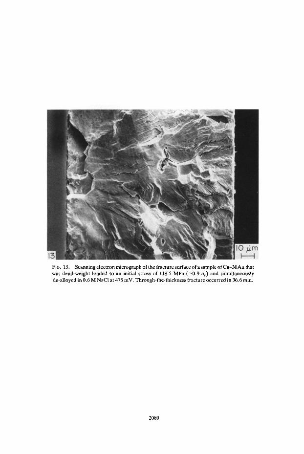
FIG. 13. Scanning electron micrograph of the fracture surface of a sample of Cu-30Au that was dead-weight loaded to an initial stress of 118.5 MPa (~0.9 ay) and simultaneously de-alloyed in 0.6 M NaCI at 475 mV. Through-the-thickness fracture occurred in 36.6 rain.
2080

+ I l l
Fro. 14. (a) and (b) Scanning electron micrographs of two opposing fracture surfaces from a sample that was simultaneously stressed and de-alloyed. The morphology of fracture is transgranular cleavage and crack arrest markings are visible. Features on the opposing
fracture surfaces are matching.
2081

FIG. 15. ScanningelectronmicrographofthefracturesurfaceofasampleofCu-30Authat was dead-weight loaded to an initial stress of 70.0 MPa (~0.5 oy) and simultaneously de-alloyed in 0.6 M NaCI at 475 inV. Through-the-thickness fracture occurred in 163 min.
2082

m
Fro. 16. Scanning electron micrograph of the fracture surface of a sample of Cu -30Au that was de-alloyed with zero applied stress in 0.6 M NaCI at 475 mV for 280 min and then dead-
weight loaded to a stress of 70 MPa. Fracture occurred during application of the load.
FIG. 17. Scanning electron micrograph of the fracture surface of a sample of Cu -30Au that was severely cold worked, then de-alloyed with zero applied stress for 30 min in 0.6 M NaCI
at +475 mV and finally impact loaded in bending.
2083

FIG. 18. Scanning electron micrograph of a portion of an intergranular facet on the fracture surface of the sample pictured in Fig. 16. The region photographed is at the
interface between the de-alloyed layer and the substrate.
FIG. 19. Back-scattered scanning electron image of the cross section of the same sample pictured in Figs 16 and 17. The region photographed is located close to the main crack.
2084

SCC of Cu-30Au 2085
scatter in the results of the AES was caused in part by the different angles presented to the incident electron beam by the different grain boundary facets and that prior to fracture de-alloying did not occur at depths from the free surface greater than 20ktm.
High resolution scanning electron microscopy was performed on the fracture surface that was within the de-alloyed layer as well as the fracture surface outside of the de-alloyed layer. A high magnification view of the fracture surface within the de- alloyed layer is presented in Fig. 5. De-alloying has resulted in the formation of a coral-type structure as was described in earlier studies. 4'5 This structure is the cause of the difference in contrast, in Fig. 2, between the de-alloyed layer and the substrate. In comparison, the portion of the fracture surface within the non-de- alloyed region was essentially featureless• Considering the limit of resolution of the scanning electron microscope, it is concluded that the fracture surface in the non-de- alloyed region is free of voids larger than 10 nm. On the basis of the results of all of the above tests, it is concluded that there is no compelling evidence of de-alloying prior to fracture along the portion of the fracture surface that is further than 20 ~m from the outer surface that was exposed to the corrodent.
When the length of time of de-alloying was decreased incrementally from 30 rain to 10 s, the thickness of the de-alloyed layer also decreased. Table 1 summarizes the average thickness of the de-alloyed layer as calculated from the measured amount of charge passed during the time of de-alloying at +475 mV and assuming that the de- alloyed layers are completely de-alloyed. Measurements were made in the scanning electron microscope of the depth of de-alloying along the grain boundaries of fractured samples. Those results indicate that the rate of de-alloying along the grain boundaries varied from one boundary to the next. In general, the measured depths of intergranular de-alloying ranged from the average value calculated by Faraday's Law (as reported in Table 1) to twice that amount. The results of impact bending and the
100
90
80
Cu at.% 70
60
50
4 0
3 0 -
2 0
1 0 -
0 0
• I " I • I " I " I " I • I
1 2 3 4 5 6 7
Point L a b e l
100
- 90
- 80
-70 AU at.%
- 60
- 5 0
- 4o
30
20
10
• 0
8
FIG. 4. Energy dispersive X-ray analysis of a specimen of Cu-30 at% Au that was stress-free de-alloyed in 0.6 M NaCI at +475 mV for 30 min and then impact bent (see Fig. 3). The results show no evidence of de-alloying in the substrate adjacent to the crack (from
points 3 to 7), however, the de-alloyed layer (points 1 and 2) is enriched in Au.

2086 J. 8. CHEN, M. SALMERON and T. M. DEVINE
TABLE 1. EFFECTS OF TIME ON DE-ALLOYING AND THICKNESS OF DE-ALLOYED LAYER ON CRACK MORPHOLOGY
De-alloying time 30 min 10 min 2 min 30 s 10 s Charge passed 22.8 C cm -2 5.6 C cm -2 1.04 C cm -2 0.388 C cm -2 0.107 C cm -2 Calculated thickness 11 pm 3/~m 0.5 ~m 0.2 #m 0.05/~m Crack morphology* 1 1 2 2 3
*Designations of crack morphology: 1--predominantly IG cleavage; 2--increased TG cleavage near the free surface, predominantly IG cleavage elsewhere; 3~increased TG cleavage near the free surface, plus ductile failure at the end of the specimen, and predominantly IG cleavage elsewhere.
observed fracture morphologies are also included in the table. Scanning electron micrographs of the fracture surfaces of samples de-alloyed for 10 min, 2 min, 30 s and 10 s are presented in Figs 6, 7, 8 and 9, respectively. As the time of de-alloying and the thickness of the de-alloyed layer decrease, a small but noticeable amount of transgranular cleavage occurs near the tensile-bend surface. However , these trans- granular cracks do not extend beyond one grain size, and the morphology of the fracture surface at a depth greater than one grain diameter is nearly 100% inter- granular. These features are especially apparent in Fig. 8, which is a scanning electron micrograph of the fracture surface of a specimen that was de-alloyed at +475 mV for 2 min and then impact bent. By further decreasing the time of de- alloying to 10 s, an additional morphology has appeared on the fracture surface. The SEM micrograph in Fig. 9 shows that intergranular cleavage did not wholly penetrate the substrate; instead, it was followed by ductile failure at the end of the specimen. The sample that was de-alloyed for 10 s did not break apart entirely when it was impact loaded. The specimen had to be removed from the solution and its fracture was completed by fatigue bending in air. Figure 10 is a scanning electron micrograph of the free surface that was exposed to the corrodent in the sample that was de- alloyed for 10 s and then impact loaded. The region depicted is located close to the main crack and includes a few secondary cracks that are predominantly intergranular but with a small quantity of transgranular cracking. This figure will be referred to in the Discussion when considering the origin of the small amount of transgranular cleavage near the beginning of the fracture surfaces in Figs 7-9. It is worth emphasizing that de-alloying for only 10 s resulted in intergranular fracture through nearly the entire thickness of the sample. It seems unlikely that this could be caused by intergranular corrosion and is additional evidence that the intergranular fracture is the result of mechanical embrit t lement of the substrate.
As indicated in Table 2, samples that were de-alloyed at 475 mV for 30 min and then left in the solution at the open-circuit potential for times of 15-30 s did not fail when impact loaded. When these samples were cross sectioned, polished and examined by SEM, cracks were found to have formed in the de-alloyed surface layer as a result of the impact loading, but these cracks did not propagate into the substrate. Figure 11 shows a micrograph of the cross section of such specimens. Cracks are initiated in the de-alloyed layer; they stop at the interface of the de- alloyed layer and the substrate. Interestingly, if, following the de-alloying treatment of 475 mV/30 min, the samples were left in the solution under freely corroding conditions for times of 5 or 10 s and then impact loaded, they failed by brittle, intergranular cleavage. The variation in potential with time of one of these samples was measured and selected values are listed in Table 3 and indicate that the open

SCC of Cu-30Au 2087
TABLE 2. EFFECT OF TIME OF FREE CORROSION ON SUSCEPTIBILITY OF CU-30 AU TO BRITTLE CRACKING
Aging time (s) 5 10 15 30 60*
Cleavage? Yes Yes No No No
Samples were de-alloyed at +475 mV, stress-free, for 30 min, then allowed to age at open-circuit potential for the lengths of time shown and were then impact bent.
*This particular sample was aged at + 150 mV for I min then impact bent. CThe presence of cleavage cracks were determined by optical and scan-
ning electron microscopy of polished cross-sections of impact-bent samples. "Yes" means that cleavage cracks propagate from the outer de-alloyed layer into the uncorroded substrate; "No" means that all the cracks initiated in the de-alloyed layer were stopped at the interface of de-alloyed layer and substrate and no cracks were found in the substrate.
TABLE 3. DECAY OF POTENTIAL WITH TIME FOLLOWING ANODIC POLARIZATION AT 475 mV
(Ag/AgCl)/30 rain
Time (s) A¢[mV (Ag/AgCI)]
0 475 0.012 420 1.2 400 3.6 380 5.0 375
10.0 360 15.0 350
TABLE4. EFFECT OF AGING TIME AT +150 mV (Ag/AgC1) ON SUSCEPTIBILITY OF Cu-30Au TO BRI1TLE
CRACKlNG
Aging time (s) 5 10 15 30
Cleavage Yes Yes No No
circuit potential had decreased below the critical potential of 400 mV (Ag/AgCI) within ~ 1 s of turning off the potentiostat. At the moment of impact loading the potential of the sample that was freely corroding for 10 s was 360 mV (Ag/AgC1), significantly below the critical potential. In addition, as summarized in Table 4, samples were de-alloyed at 475 mV (Ag/AgC1) for 30 min at zero applied stress; the applied potential was then stepped to + 150 mV, held there for 5-30 s and, finally, each sample was impact loaded. Scanning electron microscopy of the fracture surfaces indicate the samples that were polarized at 150 mV for 5 and 10 s failed by intergranular cleavage. Samples whose potentials were fixed at 150 mV (Ag/AgCI)

2088 J. S. CHEN, M. SALMERON a n d T. M. DEVINE
TABLE 5. EFFECT OF TIME OF FREE CORROSION ON SUSCEPTIBILITY OF C u - 3 0 A u TO BRITTLE
CRACKING
P r i o r t r e a t m e n t = 475 m V / 3 0 m i n + o p e n c i rcu i t /10 m i n + 475 m V / 5 s
A g i n g t ime a t o p e n c i rcu i t b e f o r e i m p a c t l o a d i n g (s) 0 15 30
C l e a v a g e yes yes n o
TABLE 6. EFFECT OF APPLIED STRESS ON CRACK MORPHOLOGY 17
Applied max. stress* 207.73 118.54 70 0 (MPa) (Fully yield) (-90% Oy) (-50% Oy) (Stress free)t
Time to fracture 36 min 36.6 min 163 min 280t min De-alloyed thickness 11 #m 11/~m 55 #m 65 #m Crack morphology~t 1 1 2 3t
*Uniaxial yield stress of specimen (Oy) is assumed to be -133 MPa, value taken from Ref. 21.
tFractured during loading to - 5 0 % ay. :~Designations of crack morphology: 1--predominately TG cleavage throughout
the specimen; 2 - - IG cracks nucleated near the tensile surface and occupied - one third of the cross section of the specimen, TG cleavage in the remaining two thirds of the substrate; 3--100% IG.
for 15 and 30 s did not fail in a brittle manner when impact loaded. Finally, three samples were anodically polarized at 475 mV (Ag/AgCI) for 30 min at zero applied stress and then allowed to freely corrode for 10 min. Next, they were each anodically polarized at 475 mV (Ag/AgC1) for 5 s. The potentiostat was then switched off and the samples were left in the solution under freely corroding conditions for 0, 15 and 30 s before impact loading. The samples allowed to freely corrode for 0 and 15 s failed by intergranular cleavage while the sample left at open cricuit for 30 s did not fail by brittle fracture when impact loaded. These results are summarized in Table 5. These results are consistent with those of Newman et al. 6 and Kelly et al. 7 who suggest that the structure of the de-alloyed layer changes with time and that it is capable of inducing cleavage of the substrate only when it is freshly formed.
To explore further the influence of de-alloying and mechanical stress on the cracking of Cu-30 Au, samples were de-alloyed and simultaneously stressed at different values of applied stress. The results are summarized in Table 6. These results were disclosed earlier 16 and are reproduced here for completeness and to facilitate the discussion of their consequences. The sample that was stressed well above its yield stress failed in 36 rain, a time known from the results in Fig. 2 to be too brief to cause through-the-thickness de-alloying. The fracture surface was nearly 100% transgranular, as shown in Fig. 12. The same was true of the sample initially loaded to - 9 0 % of its yield stress, as shown in Fig. 13. Figure 14 (a) and (b) are micrographs that show a region of transgranular cleavage from the two opposing fracture surfaces of a sample that was de-alloyed and simultaneously stressed in bending. Numerous features on the fracture surfaces match, and the fracture surface exhibits a distinct facet-step morphology and river pattern. Also shown in these figures are the "crack arrest markings" which are aligned perpendicularly to the

SCC of Cu-30Au 2089
direction of crack propagation. Similar results of transgranular cleavage of Cu3Au in salt solution were also reported by Flanagan e t al . 21 The fractography obtained on the sample stressed to = 1/2 ay and simultaneously de-alloyed is shown in Fig. 15. Cracking was initially IG, but when cracks grew and the stress at the tip of the crack reached high enough values, the cracking became TG. Because of the length of time of this test at Oappl = 1/2 Oy, it may be argued that extensive de-alloying occurred and that the sample failed because of de-alloying p e r s e and not by SCC. To check this, a sample was de-alloyed for over 4 h and then loaded to 1/2 Oy. It failed during application of the load and, as shown in Fig. 16, the fracture morphology was 100% IG. This marked difference in fracture morphology between the sample that was de- alloyed for 4 h and then impact loaded to failure and the sample that was simultaneously de-alloyed and stressed at 1/2 Cry for 4.6 h suggests that the latter sample did indeed fail by SCC.
At this juncture, it appears as though intergranular cleavage (IGC) occurs when samples are separately de-alloyed and subsequently stressed, while a mixture of IGC and TGC occurs when samples are simultaneously de-alloyed and impact bent. In order to further explore the factors that determine whether SCC occurs by IG or TG, it was decided to distinguish between the effects of dynamic strain and static strain. Consequently, samples were heavily cold worked and then allowed to stress relax at room temperature for one day before de-alloying at 475 mV/30 min with zero applied stress. When this sample was impact loaded at the conclusion of the 30 min period of de-alloying, it fractured into two parts. Figure 17 illustrates this facture surface. Note the presence of the greater amount of corrosion damage that occurs on the fracture surface closest to the free surface. This region is shown at higher magnification in Fig. 18 and illustrates the outer region which presumably failed by a combination of de- alloying and impact loading and the balance of the sample which failed by impact loading alone. Note also that the fracture surface is completely intergranular, as was the case for the non-cold worked sample that was de-alloyed in the stress-free condition (Fig. 2) and unlike the cases for the samples that were de-alloyed under the influence of an applied stress (Figs 12-15). Figure 19 is an electron back-scattered image of the cross section showing secondary cracks in the sample that was cold worked, de-alloyed and impact loaded. The cracks are intergranular and are seen to have started in the de-alloyed layer and propagated well into the substrate. The depth of de-alloying through the grains (i.e. not along the grain boundaries) is approximately twice that of the non-cold worked sample (see Fig. 3). Thus, severe cold work does enhance the rate of de-alloying but it does not change the fracture mode of samples that are impact loaded to failure after the formation of a surface de- alloyed layer.
Thus, de-alloying samples at zero applied stress for times of 10 s-30 min and subsequent impact loading causes mechanical failure by intergranular cleavage. The combination of simultaneous dynamic straining and de-alloying will cause SCC. Failure will occur by IGSCC if the applied stress is low and by TGSCC if the applied stress is high.
DISCUSSION Newman e t al . 6 reported that thin foils of a-brass that had been de-alloyed to a
shallow depth in aqueous cuprous ammonia in the absence of an applied stress failed by brittle, transgranular cleavage when bent to failure at a high strain rate. In

2090 J.S. CHEN, M. SALMERON and T. M. DEVINE
addition, Kelly et al. 7 found that Ag-20 Au that had been surface de-alloyed in 1 M HC104 in the absence of an applied stress failed in a brittle, intergranular fashion when pulled to failure at a high strain rate. In the present study, brittle, intergranular fracture was observed in thin foils of Cu-30Au that had been de-alloyed in 0.6 M NaCI in the absence of an applied stress and then impact loaded. When samples of Cu-30 Au that did not have a surface de-alloyed layer were deformed in an identical manner, they failed in a ductile manner. The ability to cause brittle failure by separately de-alloying and straining led Newman et al. 6 and Kelly et al. 7 to conclude that de-alloying induced embrit t lement of the alloy. That is, de-alloying caused the formation of a surface layer that, in turn, caused the brittle failure of the normally ductile substrate.
Kelly et al. 7 also found that brittle failure of the substrate occurred if the sample was removed from the solution immediately after de-alloying, plunged into liquid nitrogen and pulled to failure at a high strain rate. However , brittle failure did not occur if the sample was (1) allowed to warm from 77 ° K to room temperature and then pulled to failure at a high strain rate; (2) removed from the solution, dried with hot air for 2 min, reimmersed in the solution and then rapidly strained to failure; and (3) rapidly strained to failure at either 77 ° K or room temperature in the absence of prior de-alloying. Similarly, as summarized in Table 2, it was found that brittle failure of Cu-30Au would occur if the sample was impact loaded while at the de- alloying potential or if impact loaded at the open-circuit potential within 10 s of de- alloying or if impact loaded at +150 mV within 10 s of de-alloying. However , if the sample, following de-alloying, was allowed to freely corrode for 15 s or longer before impact loading or if the potential of the sample was stepped to + 150 mV and held for 15 s or longer, then cracking of the substrate would not occur.
Collectively, the above results of Newman et al.,6 Kelly et al. 7 and those of the present study are in agreement and suggest that de-alloying can induce embrittle- ment of the substrate but it can do so for only a limited period of time. The latter is referred to as an aging effect. Given the marked decrease of the surface capacitance of Cu-Au following de-alloying, measured by Pickering, 22 it has been suggested that the high concentration of vacancies formed during de-alloying condense to form voids of near atomic dimensions. 7 These voids then coarsen with time. In situ
scanning tunneling microscopy of Au-25Cu de-alloyed at potentials below the critical potential has revealed the presence of such voids and their coarsening. 23 The surface diffusion of gold is able to keep pace with the oxidation rate of copper and the surface remains planar. This structure of the surface is not capable of inducing embrit t lement of the substrate. At potentials above the critical potential the rate of oxidation of copper is so fast that the surface diffusion of gold is unable to maintain a planar interface and a highly roughened surface is created. This surface is capable of causing embrit t lement of the substrate and, if the potential is lowered to a value below the critical potential, coarsening (or, more generally, aging) occurs and the structure of the de-alloyed layer is altered from one that can induce embrit t lement of the substrate to one that cannot. The results in Table 5 which indicate that de- alloying for as little as 5 s (the shortest time employed) a sample with a previously aged surface layer will embrittle the substrate suggests that the depth of the corroded (de-alloyed) layer on the surface that is required to embrittle the substrate is =500 .~. The time to age this layer under open circuit conditions was the same as the times for aging of layers formed by de-alloying for 30 min at 475 mV (Ag/AgCI). This suggests

SCC of Cu-30Au 2091
that even for samples that possessed thick surface layers produced by de-alloying for long periods of time, the events that are responsible for embrittlement of the substrate occur within a distance of -~500 A from the interface between the de- alloyed layer and the substrate. Apparently, the rate of aging of the de-alloyed layer formed on Cu-30Au in 0.6 M NaC1 is greater than that formed on Ag-20 Au in 1 M HCIO4 .24 This might be caused by chloride ions enhancing the surface mobility of gold atoms and thereby accelerating the structural changes occurring in the de- alloyed layer. In fact, scanning tunneling microscopy of surfaces of pure gold in aqueous solutions indicate that chloride ions greatly enhance the mobility of surface atoms of gold. 25
It is worth noting that Flanagan et al. 15 have recently proposed an alternative mechanism for TGSCC in which corrosion is thought to preferentially occur along slip planes and thereby lowers the Kic for cleavage. This mechanism is consistent with the small amount of corrosion that was found necessary in the present study to cause embrittlement of the substrate. The influence of time on this mechanism needs to be specified in order to determine if it can account for the fact that de-alloying above the critical potential [400 mV (Ag/AgCI)] at zero applied stress can induce embrittlement of the substrate for times up to 10-15 s at potentials below the critical value (see Tables 2, 4 and 5).
Other research workers report that stress corrosion cracking (SCC) of Cu-Au occurs predominantly by transgranular cracking with a small amount of intergranular cracking. 5"8'9'16 Comparing these results to that reported by Kelly e t a l . ,7 as well as to the results of the present study that have been discussed to this point, raises the following important questions. First, why do Kelly e t a l . 7 and this laboratory observe intergranular fracture while others observe predominantly TG? Second, do the results of Kelly et al. 7 and the present study imply that the mechanisms of IGSCC and TGSCC of noble metal alloys are identical?
To address these questions, experiments were performed to determine what factors influence the mode of fracture of Cu-30Au. First, there was the wish to determine whether or not the intergranular fracture was caused by a preferentially high rate of de-alloying along the grain boundaries. The scanning electron micro- graphs of cross-sections of samples presented in Figs 3 and 19 show the de-alloying does occur at a higher rate along the grain boundaries than through the crystal lattice, confirming the observations of earlier researchers. 26-28 The greater rate of de- alloying along the grain boundaries is presumably the result of a lower activation- energy for oxidation of copper on the grain boundary compared to copper on the crystal lattice. In addition, the large number of vacancies formed by de-alloying may combine with the normally high diffusivity along the grain boundary to convert the grain boundaries into paths of exceptionally high diffusivity. 29 This conversion would enhance the transport of copper atoms on the grain boundary to the tip of the intergranular corrosion attack, thereby enhancing the rate of de-alloying along the grain boundaries. The magnitude of the enhanced rate of de-alloying along the grain boundaries is limited. The results of the electron back-scattered imaging of cross sections of samples with de-alloyed surface layers, the EDS measurements of copper concentrations in the substrate adjacent to the fracture surface, Auger electron spectroscopy and high resolution scanning electron microscopy of the fracture surface of samples that were sequentially de-alloyed to a small depth and then impact loaded to failure indicate that a greater depth of penetration of de-alloying occurs

2092 J.S. CHEN, M. SALMERON and T. M. DEVINE
along the grain boundaries than through the interiors of grains, but that the extent of penetration is limited. Consequently, the intergranular features that are present on the fracture surface at depths greater than that which can be accounted for by de- alloying alone must be the result of mechanical failure.
The validity of the previous sentence is confirmed by the results summarized in Table 1 of the experiments in which the time of de-alloying was progressively lowered from 30 min to 10 s. Comparison of the fractographs in Figs 2 and 6 indicates that the morphology of the fracture surface was essentially unchanged when the time of de-alloying was lowered from 30 to 10 min. The only obvious difference in the two photographs is a decrease in the size of the de-alloyed layer from approximately 20 to 5 #m. As mentioned in the Experimental Results section the measured thicknesses of the de-alloyed layers along the grain boundaries were between 1 and 2 times the average thicknesses calculated from the measured amount of anodic charge passed during de-alloying. More importantly, as shown in Table 1 and Figs 7, 8 and 9, as the time of de-alloying was reduced to 2 min, 30 s and 10 s, respectively, the fracture morphology was not substantially changed. As the time of de-alloying was de- creased, the thickness of the de-alloyed layer decreased and a small amount of transgranular cleavage occurred in the region adjacent to the surface that was exposed to the corrodent. In addition, brittle fracture propagated through 90%, rather than 100%, of the thickness of the sample that was de-alloyed for only 10 s. Presumably, the lack of through-the-thickness fracture is the result of the small thickness of the de-alloyed layer along the grain boundaries which is estimated to be approximately 0.1/~m (i.e. based on the results obtained on samples de-alloyed for 30 and 10 min, the depth of de-alloying along the grain boundaries is estimated to be approximately twice the average depth of de-alloying calculated by Faraday's Law). The cause of the small amount of transgranular cleavage that occurs near the free surface of samples that were de-alloyed for relatively short periods of time is discussed below. The point to be emphasized here is that the fracture morphology remains substantially unchanged as the time of de-alloying is decreased from 30 min to 10 s and this is offered as evidence that the failures during subsequent impact loading were caused by mechanical fracturing of the grain boundaries and not by intergranular corrosion.
The factors that determine whether the substrate that lies beneath a de-alloyed layer will fail by intergranular cleavage or transgranular cleavage are now con- sidered. For the results of the impact tests performed on samples that were de- alloyed in the absence of an applied stress, there are two questions that need to be addressed. First, why is the crack brittle and intergranular? Second, why is the crack able to propagate such a great distance into the usually ductile substrate? Since, as shown in Figs 3 and 19, the depth of de-alloying is greater along the grain boundaries, it is reasonable to expect a crack to initiate and propagate intergranularly through the de-alloyed layer. It is hypothesized that fracture of the substrate during impact loading also occurs intergranularly because the intergranular crack in the de-alloyed layer reaches a sufficiently high velocity before it enters the substrate that strains at the tip of this growing crack are smaller (than at the tip of a blunted, stationary crack of the same size),3°'31 making it easier for this crack to continue to propagate than for a transgranular crack to nucleate and grow. The intergranular crack propagates far into the substrate because significant strain hardening occurs in the material ahead of the crack so that its plastic zone is relatively small (compared to a stationary crack of

SCC of Cu-30Au 2093
the same length), 3°'31 making blunting more difficult. It is important to emphasize that impact or high strain-rate loading is necessary for the extensive propagation of the brittle intergranular crack into the matrix because (1) if the strain rate were too slow, coarsening of the de-alloyed layer would occur before failure and (2) the high strain rate imparts high velocity to the intergranular crack before it enters the substrate. The high velocity inhibits blunting of the crack. 31
Intergranular cleavage occurs in samples that were simultaneously de-alloyed and loaded to a low stress, while transgranular cleavage occurs in samples that were de-alloyed and simultaneously loaded to a high stress. Table 617 summarizes the results of the influence of the magnitude of the stress that is applied concurrently with de-alloying on the fracture morphology. In addition, fractographs of samples that were stressed to greater than the general yield stress, to approximately 90% of the yield stress in the outermost fiber of the bent beam, and to approximately 50% of the yield stress, are presented in Figs 12, 13 and 15, respectively. It is concluded from observations of these figures that, as the magnitude of the stress that is applied during de-alloying is raised above some critical (but unspecified) value, the mode of failure changes from predominantly intergranular to predominantly transgranular. This is particularly apparent in the case of the sample (Fig. 15) that was simultaneously de- alloyed and subjected to an applied stress approximately equal to one-half the yield stress. The initial cracks were predominantly intergranular. However, as these cracks grew and the applied stress was consequently raised, the fracture morphology became predominantly transgranular cleavage.
Supplementary evidence for a change in fracture morphology with the magnitude of the applied stress is provided by the fractographs in Figs 7, 8 and 9 of the samples that were de-alloyed (in the absence of applied stress) for short periods of time and then impact loaded. Apart from small amounts of transgranular cleavage near the outer surface, the fracture mode was entirely intergranular. The scanning electron micrograph in Fig. 10 of the free surface of a sample that was de-alloyed with zero applied stress for 10 s and then impact loaded depicts some secondary cracks that were present close to the main crack. The cracks are predominantly intergranular with a few segments that are transgranular. We suggest that short times of de- alloying produce thin de-alloyed layers (=0.05-0.1 pm following 10 s of de-alloying) and depths of penetration of de-alloying along grain boundaries that are short and highly varied and dependent on the crystallographic mismatch across the grain boundary. During impact loading, intergranular cracks open up along those grain boundary facets that are most severely de-alloyed and which have the highest resolved normal stress. A ligament of uncracked material that lies between two adjacent, shallow intergranular cracks would be highly stressed. Consequently, such regions fail by transgranular cleavage. As the various crack segments link-up to form a single, wide (dimension on the free surface) but shallow crack, the stress in the uncracked region is at a relatively low value and the entire crack propagates intergranularly.
Another interesting point can be seen from Fig. 9 and Table 1. As the thickness of the de-alloyed layer decreases even further, the IG cleavage does not fully penetrate the specimen. Some ductile failure is seen at the outer edge of the specimen. The decreased extent of crack propagation into the substrate is possibly the result of lower misfit stresses developing in the substrate at the de-alloyed layer-substrate interface as the thickness of the de-alloyed layer decreases. For the sample that was
2094 J.S. CHEN, M. SALMERON and T. M. DEVINE
de-alloyed, then allowed to coarsen, de-alloyed again for 5 s and then impact loaded, the depth of the new de-alloyed layer was -~250-500 ~ and the depth of penetration of the crack into the substrate was =50 ktm. The sample that was de-alloyed for 10 s and then impact loaded had a de-alloyed layer that was estimated to be 500-1000 ~, thick and the depth of penetration of the crack into the substrate was ~-100/~m. Thus the extent of crack propagation into the substrate is far in excess of the depth of de- alloying and the distance of propagation of the crack into the substrate may increase as the amount of de-alloying increases. This result may be explained by Sieradzki and Newman 13'14 who have proposed that the product of lattice misfit (between film and substrate) and the square root of film thickness can serve as a driving force for cleavage, provided that the film is in a tensile stress state. Nevertheless, Fritz et al. 9
have recently determined by X-ray stress measurements that the de-alloyed layer of polycrystalline Cu-18% Au formed in an acidic sulfate solution actually displays a compressive stress rather than a tensile stress. The film that was analysed had coarsened and may bear little resemblance to the film present at the time of embritt lement. As mentioned above, the small amount of corrosion that was required to cause brittle behavior of the substrate is consistent with the model of TGSCC of Flanagan et al . 15 However , once again, it is not clear that this model can account for the substrate continuing to fail in a brittle manner when impact loading is delayed for up to 10-15 s after de-alloying has ceased.
Before consideration is given to why a large applied stress causes transgranular cleavage while a low applied stress causes intergranular cleavage of samples that are simultaneously being de-alloyed, it is worth noting that the strain that occurs within the sample must be dynamic (as opposed to static), as well as large, in order for transgranular cleavage to occur, instead of intergranular cleavage. Proof of this statement was provided by the results of the tests performed on a sample that was first severely deformed by repeated bending over a cylindrical mandrel with a diameter of 1 cm, then allowed to stress-relax at room temperature for 24 h, followed by de-alloying with zero applied stress for 30 min and finally impact loaded to failure. As shown in Fig. 17, the fracture surface of this sample was predominantly intergranular and looked similar to the fracture surface of the sample that was not deformed prior to de-alloying (Fig. 2). Thus, transgranular SCC only occurs if the sample is simultaneously de-alloyed and stressed to a high value (i.e. from the results in Table 4, the nominal stress must be -> the yield stress).
There are two effects of the applied stress that need to be considered when addressing the issue of its influence on the mode of SCC. First, the magnitude of the applied stress can influence the magnitude of local stresses within the microstructure. Secondly, the applied stress can influence the rate of de-alloying. Succinctly stated, the present results suggest that the occurrence of either intergranular or transgranu- lar SCC is determined by the magnitude of local stresses in the microstructure. It is known that plastic deformation is inhomogeneously distributed throughout the microstructure in a polycrystalline sample that is deformed to a small, macroscopic plastic strain. 32 In particular, measurements of microhardness as a function of position within the microstructure of a lightly deformed polycrystal indicate that the regions adjacent to the grain boundaries have a substantially higher hardness than regions located near the center of a grain.33--35 In the interior of the grain, slip occurs on a single system for small amounts of macroscopic plastic deformation so the local

SCC of Cu-30Au 2095
rate of strain hardening is low. Because of the misorientation of the primary slip system in one grain relative to the other, slip near a grain boundary is forced to occur on multiple systems in order to maintain continuity of strain across the grain boundary. Slip on one system interferes with that on another, resulting in local strain hardening. As the amount of macroscopic plastic strain increases, slip on secondary systems occurs in the interiors of grains and the local rate of strain hardening increases there as well.
At low values of applied stress, the local stresses near the grain boundaries are higher than in the grain interiors. Therefore, the rate of de-alloying in samples that are simultaneously stressed (at lower values) and de-alloyed is even higher along the grain boundaries because of the additional strain energy. This in turn accelerates the nucleation of cracks along the grain boundaries. As the intergranular crack propa- gates, the nominal stress, on the remaining uncracked material increases and significant straining occurs throughout each grain. Therefore, the rate of de-alloying in the interior of grains becomes more comparable to that along grain boundaries and cracking will occur transgranularly as well as intergranularly.
At high values of applied stress, the local stresses in the interiors of grains are high and it is suggested that intragranular slip permits the rate of de-alloying through the grain interior to keep up with that along the grain boundaries. There are several mechanisms whereby intragranular plastic deformation could accelerate the rate of de-alloying through the grain interior. First, the reactivity of the atoms around the cores of dislocations is higher than those in the unstrained lattice. Secondly, the increased density of dislocations may enhance the rate of transport of copper atoms to the interface between the substrate and the de-alloyed layer by dislocation pipe diffusion. 29 Thirdly, the formation of surface slip steps can enhance the rate of de-alloying by either shortening the diffusion path of copper to the surface or by continually exposing fresh copper atoms to the aqueous solution (dynamic straining). 36 Dynamic straining has been observed to greatly enhance the de-alloying rate of Cu-Zn 29 and Cu-Au alloys. 36 For grains that are suitably oriented with respect to the applied stress, cracking of the substrate will nucleate and propagate transgranularly.
The electrochemical contribution to SCC is the same for both IGSCC and TGSCC of Cu-30Au. The SCC may be either intergranular or transgranular depending upon the magnitude of the local stress within the microstructure. Measurements of acoustic emission and current transients by Pugh and co-workers, 37-3s and Newman and Sieradzki 39 on samples of copper-zinc alloys that are undergoing TGSCC suggest the occurrence of discontinuous crack propagation. The scanning electron micrographs in Fig. 14 (a,b) of opposing-fracture surfaces that formed by TGSCC indicate the presence of crack arrest markings (CAM). These markings suggest that TGSCC occurs by a process of discontinuous cleavage and the incremental cleavage distance is -1/~m. CAM were not found on the surfaces of samples that failed by IGSCC. Nevertheless, the fact that the intergranular crack did not propagate completely through the sample that was de-alloyed at zero applied stress for 10 s and impact bent suggests that IGSCC may also propagate disconti- nuously.
In conclusion, for Cu-30Au in 0.6 M NaC1, the electrochemical aspects of the mechanism of IGSCC are identical to those of TGSCC.

2096 J.s. CHEN, M. SALMERON and T. M. DEVINE
SUMMARY AND CONCLUSIONS (1) Samples of Cu-30Au that were 120 /~m thick and that were anodically
polarized at +475 mV (Ag/AgC1) in 0.6 M NaCl for 30 min with zero applied stress were de-alloyed to a depth of approximately 20 ktm. When impact loaded, they failed through-their-thickness and the morphology of the fracture surface was intergranu- lar. Electron-back scattered images and energy dispersive X-ray analyses of cross- sectioned samples, as well as Auger electron spectroscopy and high resolution scanning electron microscopy of the fracture surface indicate that the depth of de- alloying was 20 /~m and that the balance of the sample failed by mechanical intergranular cleavage with no direct assistance of corrosion.
(2) Samples of Cu-30Au were sequentially de-alloyed at +475 mV (Ag/AgCl) in 0.6 M NaCl for times ranging from 30 min to 10 s and then impact loaded. Samples that were de-alloyed for 30 min, 10 min, 2 min and 30 s failed by intergranular cleavage. Samples that were de-alloyed for only 10 s failed by intergranular cleavage through 90% of their thickness, at which point the cleavage crack was arrested. These results confirm that intergranular failure of the substrate occurs by mechanical fracture of non-de-alloyed material.
(3) Samples of Cu-30Au were de-alloyed with zero applied stress at +475 mV (Ag/AgCl) in 0.6 M NaC1 for 30 min, at which point either (i) the potentiostat was turned off and the samples remained in the test solution at the open-circuit potential for times ranging from 5 to 30 s and were then impact loaded or (ii) the potential was stepped to + 150 mV (Ag/AgC1) and held there for times ranging from 5 to 30 s and were then impact loaded. Cracks propagated through the de-alloyed layer but not into the substrate of samples that had been either freely corroding or at + 150 mV (Ag/AgCl) for times of 15 s or longer. Cracks propagated by intergranular cleavage through the substrates of samples that were at either their open-circuit potential or + 150 mV (Ag/AgCl) for 5 and 10 s. Those results suggest that de-alloying causes changes in the surface layer that, for a short period of time, are capable of inducing brittle failure of the substrate.
(4) Samples of Cu-30Au that were severely cold worked, then de-alloyed at 475 mV for 30 min and finally impact loaded failed intergranularly.
(5) Samples of Cu-30Au that were simultaneously stressed and de-alloyed at 475 mV failed in a brittle manner. Samples subjected to high stress (i.e. -> yield stress) failed by transgranular cleavage. Samples subjected to low stresses failed intergranu- lady.
(6) It is concluded that the electrochemical contribution to the stress corrosion cracking of Cu-30Au in 0.6 M NaCl is the same for both IGSCC and TGSCC; the magnitude of the applied stress determines whether the SCC will be intergranular or transgranular.
Acknowledgements--The authors would like to thank Dr J. J. Gilman and Professor R. O. Ritchie for several discussions during the course of this work. Special thanks to Dr D. F. Ogletree for assistance with Auger electron spectroscopy; Mr R. Wilson with assistance of scanning electron microscopy and Mr J. Wu for providing the test materials. This research was supported by a University of California Fellowship (J.S.C.), a grant from the Office of Defense Waste and Transportation Management, which oversees the Waste Acceptance Process for the Defense Waste Processing Facility (J.S.C. and T.M.D.), and the Division of Materials Sciences, Office of Basic Energy Sciences of the U.S. Department of Energy under contract No. DE-AC03-76SF0098 (M.S.).

SCC of Cu-30Au 2097
R E F E R E N C E S 1, U. BERTOCCI, J. electrochem. Soc. 136, 1887 (1989). 2, M. POURSAIX, Atlas of Electrochemical Equilibria in Aqueous Solutions. NACE, CEBELCOR,
Houston, TX (1974). 3. R. C. NEWMAN and K. SIERADZKI, Chemistry and Physics of Fracture (eds R. M. LATANISION and R. H.
JONES), p. 597. Martinus Nijhoff Publishers, Dordrecht (1987), 4. T. B. CASSAGNE, W. F. FLANAGAN and D. B. LICHTER, Metall. Trans. 17A, 703 (1986). 5. T. B. CASSAGNE, W. F. FLANAGAN and B. D. LICHTER, Metall. Trans. 19A, 281 (1988). 6. R. C. NEWMAN, T, SHAHRABI and K. SIERADZlCl, Scripto Metall. 23, 71 (1989). 7. R. G. K~LLY, A. J. FROST, T. SHAHRABI and R. C. NEWMAN, Metall. Trans. 22A, 531 (1991). 8. J. D. FRITZ, B. W. PARKS and H. W. PICKERING, Scripta Metall. 22, 1063 (1988). 9. J. D. FRITZ, B. W. PARKS and H. W. PrOCERING, Environmentally Assisted Cracking: Science and
Engineering, ASTM STP 1049 (eds W. B. LISAGOR, T. W. CROOgER and B. N. LHs), 76 (1990). 10. J. S. CHEN, M. SALMERON and T. M. DEVINE, J. electrochem. Soc. 139, L55 (1992). 11. C. EDELEANU, Physical Metallurgy of Stress Corrosion Fracture (ed. T. N. RHODIN), p. 79.
Interscience, New York (1959). 12. A. J. FORTY, PhysicalMetallurgy of Stress Corrosion Fracture (ed. T. N. RHODIN), p. 99. Interscience,
New York (1959). 13. K. S1ERADZKI and R. C. NEWMAN, Phil. Mag. A. 51, 95 (1985). 14. K. S1ERADZKI and R. C. NEWMAN, J. Phys Chem. Solids 48, 1101 (1987). 15. W. F. FLANAGAN, P. BASTIAS and B. D. LIC}~TER, Acta Metall. Mater. 39, 695 (1991). 16. B. D. LITCHER, T. B. CASSACNE, W. F. FLANAGAN and E. N. PUGH, Microstruct. Sci. 13,361 (1985). 17. J. S. CHEN, M. SALMERON and T. M. DEWNE, Scripta. Metall. 26, 739 (1992). 18. C. D. BEACHEM, Metall. Trans. 3, 437 (1972). 19. J. CONCLETON, J. YU and R. N. PARKINS, Mater. Sci. Technol. 1, 1046 (1985). 20. H. W. PICr¢ERING, Corros. Sci. 23, 1107 (1983). 2l. W. F. FLANAGAN, J. B. LEE, D. MASSINON, M. ZHu and B. D. L~CHTER, Environmentally Assisted
Cracking: Science and Engineering, ASTM STP 1049 (eds W. B, LISAGOR, T. W. CROOKER and B. N. LE1S), p. 86 (1990).
22. H. W. PICKERIN6, J. electrochem. Soc. 115, 690 (1968). 23. J. S. CHEN, ?. FAUSTO, M. SALMERON and T. M. DEVINE, Research in Progress Syrup., Corrosion '92,
Annual Meeting NACE, Cincinnati, OH (1992). 24. R. C. NEWMAN, written communication (31 October 1991). 25. D. J, TREVOR, C. E. D. CHIDSEV and D. M. LOIACONO, Phys. Rev. Letts. 62, 929 (1989). 26. W. D. ROSERTSON and R. BAKISH, Stress Corrosion Cracking and Embrittlement (ed. W. D.
ROSERTSON), p. 33. John Wiley, NY (1956). 27. L. GRAF, Fundamental Aspects of Stress Corrosion Cracking (eds R. W. STAEHLE, A. J. FORTY and D.
VAN ROOYAN), p. 187. NACE, Houston, Texas (1969). 28. L. GRAF, The Theory of Stress Corrosion Cracking in Alloys (ed. J. C. SCULLY), p. 399. NATO,
Brussels (1971). 29. A. PARTHASARATHE and N. W. POLAN, Metall. Trans. 13A, 2027 (1982). 30. J. C. LAUTRIDOU and A. PINEAU, Int. J. Fracture 17, Rl15 (1981). 31. L. B. FnEUND and J. W. HUTCmNSON, J. Mech Phys. Solids 33, 169 (1985). 32. R. W. K. HONEYCOMnE, The Plastic Deformation of Metals, pp. 220-224. E. Arnold, London (1968). 33. W. Boas and M. E. HARGREAVES, Proc. R. Soc. A193, 89 (1948). 34. V. M. URIE and H. L. WAIN, J. Inst. Metals 81,153 (1952). 35. D. MCLEAN, Grain Boundaries in Metals, p. 166-172. Oxford University Press, London (1957). 36. H.W. PlC~¢ERING, FundamentalAspects of Stress Corrosion Cracking (eds R. W. STAEr~LE, A. J. FORTY
and D. VAN ROOYAN), p. 159. NACE, Houston, Texas (1969). 37. J. A. BEAVERS and E. N. PUGH, Metall. Trans. l l h , 809 (1980). 38. D.V. BEGGS, M. T. HAHN and E. N. PUGIq, Hydrogen Embrittlement and Stress Corrosion Cracking,
p. 181. ASM, Metals Park, Ohio (1984). 39. R. C. NEWMAN and K. SmRADZKI, Scripta. Metall. 17,621 (1983).