interim service isdn satellite (isis) hardware experiment design … · interim service isdn...
TRANSCRIPT

GovernmentSystems
Interim Service ISDN Satellite (ISIS)
Hardware Experiment Design
for
Advanced ISDN Satellite
and Experiments
Design
28 February 1992
_:::7_I t '':_ 0 0......... 7 0 3 3 0
Task Completion Report
NASA SCAR Contract NASW-4520, 13 Sep 1990
Prepared byGerard R. Pepin
GTE/Government Systems15000 Conference Center Drive
Chantilly, Virginia 22021-3808
https://ntrs.nasa.gov/search.jsp?R=19920008366 2018-08-30T10:11:11+00:00Z

NASANational Aeronautics and
Space Administration
1. Report No.
Report Documentation Page
2. Government Accession No: 3. Recipient's Catalog No.
4_ Titl0 an_Subtjtlentenm service ISDN Satellite (ISIS) Hardware Experiment
Design for Advanced Satellite Designs and Experiments (Task
Completion Report)
7. Author(s)
Gerard R. Pepin
9. Performing Organization Name and Address
GTE Government Systems15000 Conference Center Drive
P.O. Box 10814
Chantilly, VA 22021-3808
12. Sponsoring Agency Name and Address
NASA HeadquartersHeadquarters Acquisition Division300 7th Street, SWWashington, DC 20546-0001
5. Report Date
28 February 19926. Performing Organization Code
8. Performing Organization Report No.
10. Work Unit No.
11. Contract or Grant No.
NASW-4520
13. Type of Report and Period Covered
ISIS Hardware Experiment Design Task
Completion Report (1 MAY 91 - 28 FEB 92)
14. Sponsoring Agency Code
15. Supplementary Notes
16. Abstract
The Interim Service ISDN Satellite (ISIS) Hardware Experiment Design for Advanced Satellite Designs
describes the design of the ISDN Satellite Terminal Adapter (ISTA) capable of translating ISDN protocoltraffic into TDMA signals for use by a communications satellite. The ISTA connects the NT1 via theU-interface on the line termination side of the CPE to the V.35 interface for satellite uplink. The sameISTA converts in the opposite direction the V.35 to U interface data with a simple switch setting.
........ ,+'
17. Key Words (Suggested by Author(s))
ISDN, satellite, traffic network, simulation,ISDN standards, B-ISDN, frame relay, on-orbit
switching, computer networks, satellite orbits,satellite transmission quality, networkconfiguration, traffic model
18. Distribution Statement
Unclassified-Unlimited
19. Security Classif. (of this report)
Unclassified
20. Security Classif. (of this page)
Unclassified
21. No. of pages 22. Price

SECTION 1
INTRODUCTION
1.1 Background
The objectives of this element of the NASA Satellite Communications ApplicationsResearch (SCAR) Program are to develop new advanced on-board satellite capabilities thatwill enable the provision of new services, namely interim and full Integrated Services
Digital Network (ISDN) services via satellite and to provide a system analysis of futuristicsatellite communications concepts, namely broadband services via satellite.
This aspect of the NASA SCAR Program provides a research and development effort to:
1) develop basic technologies and concepts to use the on-board processing andswitching capabilities of advanced satellites that will enable the provision ofinterim and full ISDN services and
2) provide a systems and requirements analysis of future satellitecommunications concepts based on a new generation of broadband
switching and processing satellites.
These objectives will be achieved in part by designing and implementing hardware tointerface between terrestrial ISDN networks and a communications satellite, possibly with
the Advanced Communications Technology Satellite (ACTS).
1.2 Scope
This task completion report documents the ISDN Satellite Terminal Adapter (ISTA) designassociated with the Interim Services ISDN Satellite (ISIS) architecture. The process and
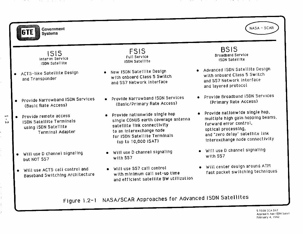
methodology is applicable to the ISIS system as described in Figure 1.2-1, "NASA/SCARApproaches for Advanced ISDN Satellites". The ISIS Network design represents satellitesystems like the Advanced Communications Technology Satellite (ACTS) orbiting switch.
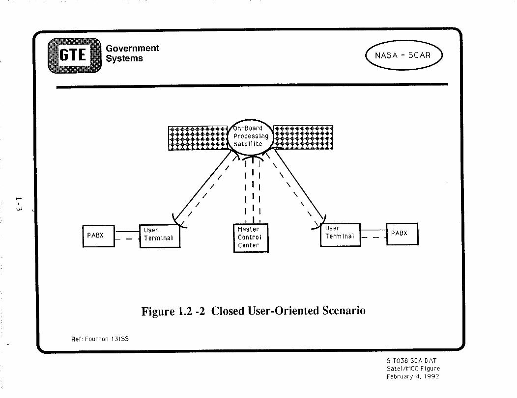
The ACTS will be controlled by a Master Ground Station (MGS) shown in Figure 1.2-2,"Closed User-Oriented Scenario". A user of the ACTS satellite orbiting switch requestsservices from the MGS, a combination of the NASA Ground Station (NGS) and the MasterControl Station (MCS). The MGS, in turn, commands the satellite to switch the
appropriate communications channel.
The ultimate aim of this element of the SCAR Program is to move these MGS functions on-
board the next generation ISDN communications satellite as shown in Figure 1.2-3,"Advanced ISDN Satellite". The technical and operational parameters for the advancedISDN communications satellite design will be obtained from an engineering software modelof the major subsystems of the ISDN communications satellite architecture. Discrete eventsimulation experiments will be performed with the model using various traffic scenarios,
design parameters, and operational procedures. The data from these simulations will beanalyzed using the NASA SCAR performance measures discussed in previous reports.Data from hardware experiments will used to verify the model results.
In order to associate modeling and simulation results with real-world data, some ISDN
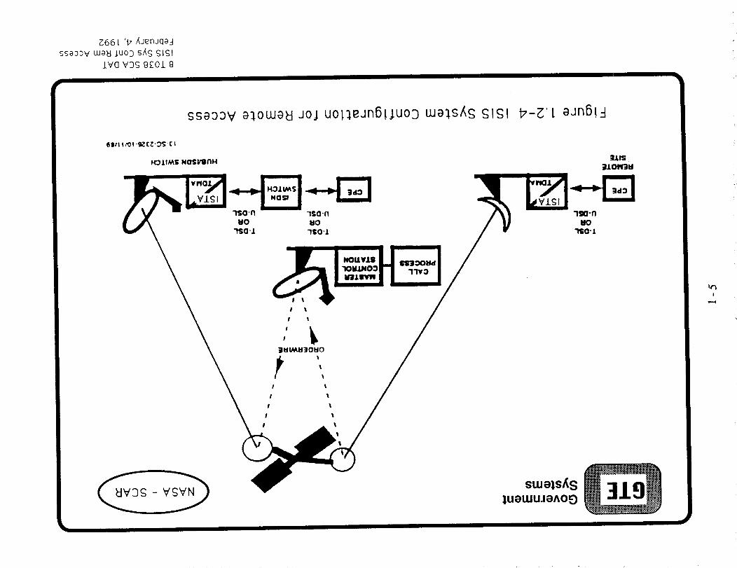
hardware design and implementation were undertaken. Hardware development was limitedto the ISIS approach. Figure 1.2-4, "ISIS System Configuration for Remote Access",
1-1
GovernmentSystems
ISISInterim ServiceISDN Satellite
ACTS-like Satellite Design
and Transponder
Provide Narrowband ISDN Services
(Basic Rate Access)
Provide remote access
ISDN Satellite Terminals
using ISDN SatelliteTerminal Adapter
Will use D channel signaling
but NOT SS7
Will use ACTS call control and
Baseband Switching Architecture
FSISFull Service
ISDN Satellite
New ISDN Satellite Design
with onboard Class 5 Switchand 5S7 Network Interface
Provide Narrowband ISDN Services
(Baslc/Primary Rate Access)
Provide nationwide single hop
single CONUS earth coverage antennasatellite link connectivity
to an lnterexchange node
for ISDN Satellite Terminals
(up to 10,000 ISAT)
Will use D channel signaling
with 5S7
Will use SS7 call control
with minimum call set-up time
and efficient satellite BW utilization
BSISBroadband Service
ISDN Satellite
Advanced ISDN Satellite Design
with onboard Class 5 Switch
and 5S7 Network Interface
and layered protocol
Provide Broadband ISDN Services
(Primary Rate Access)
Provide nationwide single hop,
multiple high gain hopping beams,
forward error control,
optical processing,and "zero delay" satellite link
interexchange node connectivity
Will use D channel signaling
w i th SS7
Will center design around ATM
fast packet switching techniques
Figure 1.2-I NASA/SCAR Approaches for Advanced ISDN Satellites
5 T038 SEA DAT
Approach Aav ISDN 5atel
February 4, 1992
I
GovernmentSystems
PABX
Figure 1.2-2 Closed User-Oriented Scenario
Ref: Fournon 131SS
5 T038 SCA DAT
Satel/MCC Figure
February 4, 1992

|
_ GovernmentSystems
Controlransit
Exchange
ProcessingSatellite
Network Network
Terminal Terminal
t Local I ! LocalExchange Exchange
Figure 1.2-3 Advanced ISDN Satellite
_PABX l
5 T038 SCA DAT
Adv ISDN Satel
February 4, 1992
Z661 '17 _aenJqa-I
ssaaaV cuakt _uo3 sag cjICJI
iV(] VDCJ g£Ol g
ssaaov a_,ouJa_lao.l uo!:ieanB!juoD tua]s_S SlSl b-_'I aan6!-!
6111tit0!-9_C,_'_ C
H_IIM$ NOSI/llnH
suJels_s:IUeUJUJ_)AO_
V3!

illustrates the ISIS system configuration. The ISDN Satellite Terminal Adapter (ISTA) wasdesigned to interface with the Type 1 network termination (NT1) at the user site via theISDN U-interface and the line termination (LT) unit of the ISDN switch.
1.3 Document Overview
This task completion report begins by describing the objectives of the ISIS hardwareexperiment in terms related to a communications satellite connected to an ISDN terrestriallink. A specific application of sending compressed video from NASA Lewis in Cleveland,Ohio to the GTE #5ESS switch in Chantilly, Virginia is postulated as a context for
discussions for the design of the ISTA.
The ISTA design is decomposed into several detailed views identifying the designrefinements along the way. These design views are described in terms of their associatedhardware, the chip set, and the software design. The ISDN basic access superframestructure and the satellite link access HLDC Frame Structure are described down to the bit
level.
The ISTA activation and deactivation protocols for both the exchange and terminal
equipment are presented in the context of end-to-end Z-diagrams. The relationship betweenthe 68000 Development System and the ISTA is shown and a detail circuit design down tothe chip pin connections is provided.
1-6

SECTION 2
POTENTIAL ISDN HARDWARE EXPERIMENTS
2.1 ISDN Hardware Experiment Objective
The objective of the ISDN Hardware Experiment is to demonstrate the feasibility of usingtypical communications satellites to connect ISDN users to ISDN exchanges via a non-ISDN Communications Satellite Link. Figure 2.1-1, "ISIS Hardware Development"
shows the top view of a User Terminal connected to a #5ESS Switch via line terminationand network termination. The ISTA converts the ISDN Basic Access Superframe Structureinto Satellite Link Access HDLC Frame Structure suitable for transmission via satellite.
The ISTA design must also be capable of reversing the process on the network side of thesatellite connection.
2.2 ISDN Typical Basic Access - Terrestrial/Satellite Links
Figure 2.2-1, "ISDN Typical Terrestrial/Satellite Links", shows costumer premisesconnected to an ISDN switch at a local telephone exchange by a U-interface with 3.5 miles
of twisted pair copper wire. This connection between the NT1 unit and the line termination(LT) provides the user with all the access for basic rate ISDN services.
Replacing this copper wire with a satellite link requires matching both the NT1 and the LTtermination in terms of bit transfer, protocol timing and data rate adaption related to CcITrtime-out values. Both the satellite and the corresponding ground system must be capable of
supporting the typical ISDN 160Kbps basic access rate. The ISTA ensures that the protocoland user data conversions permit the timely support of the ISDN protocol and data.
2.3 Potential Application of ISTA
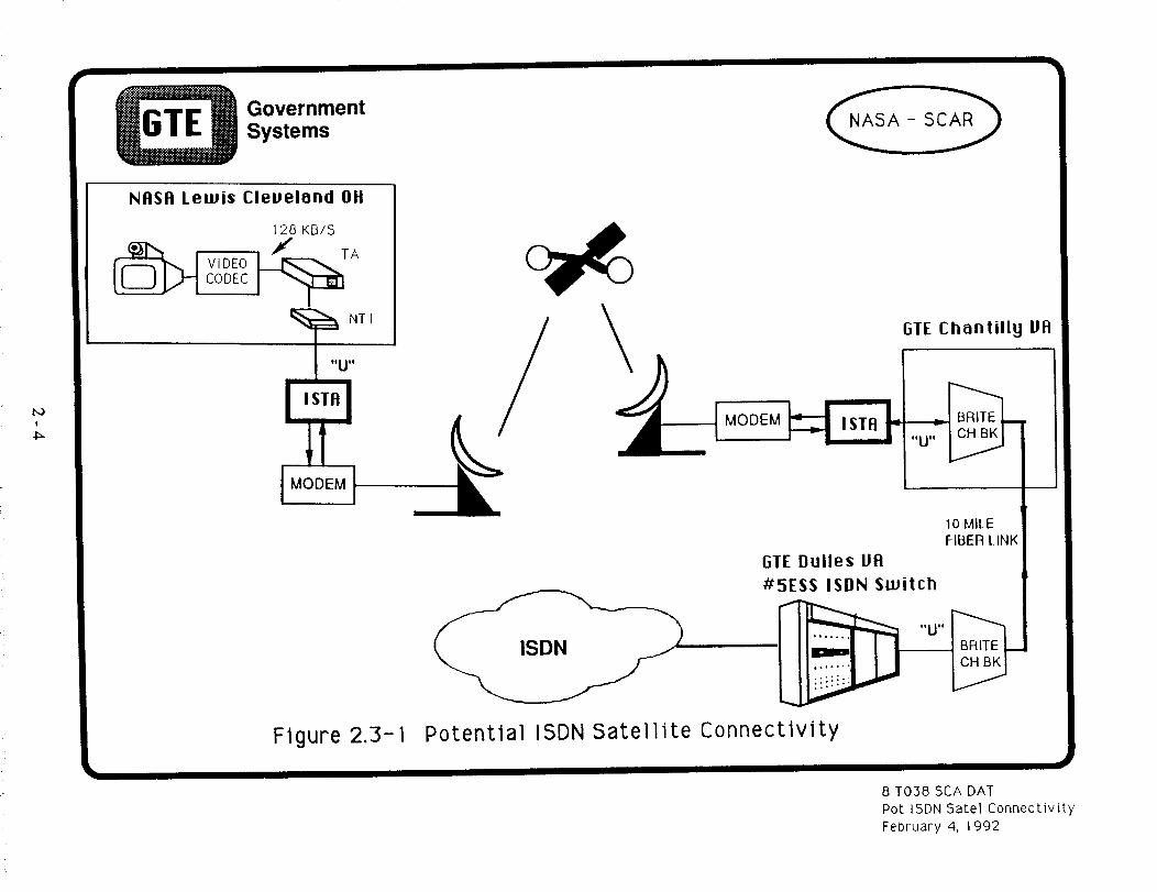
One of the postulated demonstrations of the ISTAs is to provide ISDN connectivitybetween the NASA Lewis Complex and the GTE #5ESS at Dulles International Airport.
Figure 2.3-1, "Potential ISDN Satellite Connectivity", shows a compressed video image atNASA Lewis, Cleveland, Ohio being transmitted to GTE Chantilly, Virginia via ISTA
equipped ground terminals. From GTE-Chantilly the ISDN frames pass through a U-interface in the Brite Channel Bank across 10 miles of fiber optic link to a Brite channelbank in the GTE Dulles #5ESS ISDN Switch. Tests of throughput and response-time can
be made using this configuration or other similar configuration. The principal message forthis report is that the ISTA provides the necessary conversion between the ISDN world andthe satellite world.
2-1

GTELaboratories
Incorporated
C User "_Termlnal_
ISTA
I Network ITermination I
\
//
I Satelllte rModem /
HDLC IProcessor
\
Figure 2.1-I ISIS Hardware Development
5 T038 SCA DATISIS Hardw Devel BriefFebruary 4, 1992

1,oI
r"_]
_ GovernmentSystemsISDN
TYPICAl_ BASIC ACCESS - -iERRESIItlAL
CUSTOMER'S I
PREMISES I
NTl F lI
CUSTOMER'S
PREMISES
U INTERFACE
3 5 MII. ES Wl] It A
TWIS1ED PAIR
(NON-lOADED)
L_INKi
NTI
LOCAL ]ELCO
160 KBPS [ liX
IYPICALBASICACCESS SAIl lillE LINK
I " t_--"
I MODEM
IF
i OCAI. I LI (;_..
--- IISL)I 1l i l:_Wlll:ll
Figure2.2-1 ISDNTypicalTerrestrial/SatelliteLinks
8 T038 SCA DAT
ISIS Sys Conf Rein Access
February 4, 1992
I
4_
_ overnmentSystems
NASA Lewis Cleveland OH
128 KB/S
Figure 2.3- 1
GTE Chantilly VA
i MODEM _ I ISTA FI
10 MILE
FIBER LINK
GTE Dulles VA
#5ESS ISDN Switch
Potential ISDN Satellite Connectivity
8 T038 SCA DAT
Pot ISDN Satel Connectivity
February 4, 1992
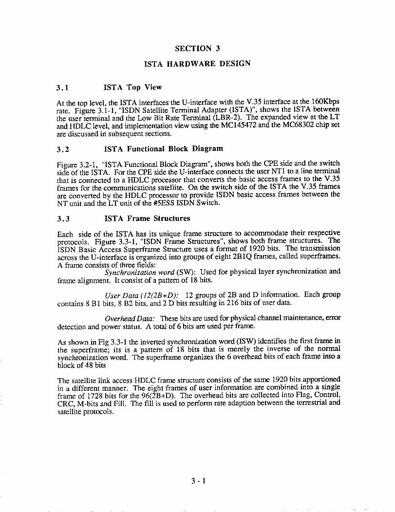
SECTION 3
ISTA HARDWARE DESIGN
3.1 ISTA Top View
At the top level, the ISTA interfaces the U-interface with the V.35 interface at the 160Kbpsrate. Figure 3.1-1, "ISDN Satellite Terminal Adapter (ISTA)", shows the ISTA betweenthe user terminal and the Low Bit Rate Terminal (LBR-2). The expanded view at the LT
and HDLC level, and implementation view using the MC145472 and the MC68302 chip set
are discussed in subsequent sections.
3.2 ISTA Functional Block Diagram
Figure 3.2-1, "ISTA Functional Block Diagram", shows both the CPE side and the switchside of the ISTA. For the CPE side the U-interface connects the user NT1 to a line terminal
that is connected to a HDLC processor that converts the basic access frames to the V.35frames for the communications satellite. On the switch side of the ISTA the V.35 frames
are converted by the HDLC processor to provide ISDN basic access frames between theNT unit and the LT unit of the #5ESS ISDN Switch.
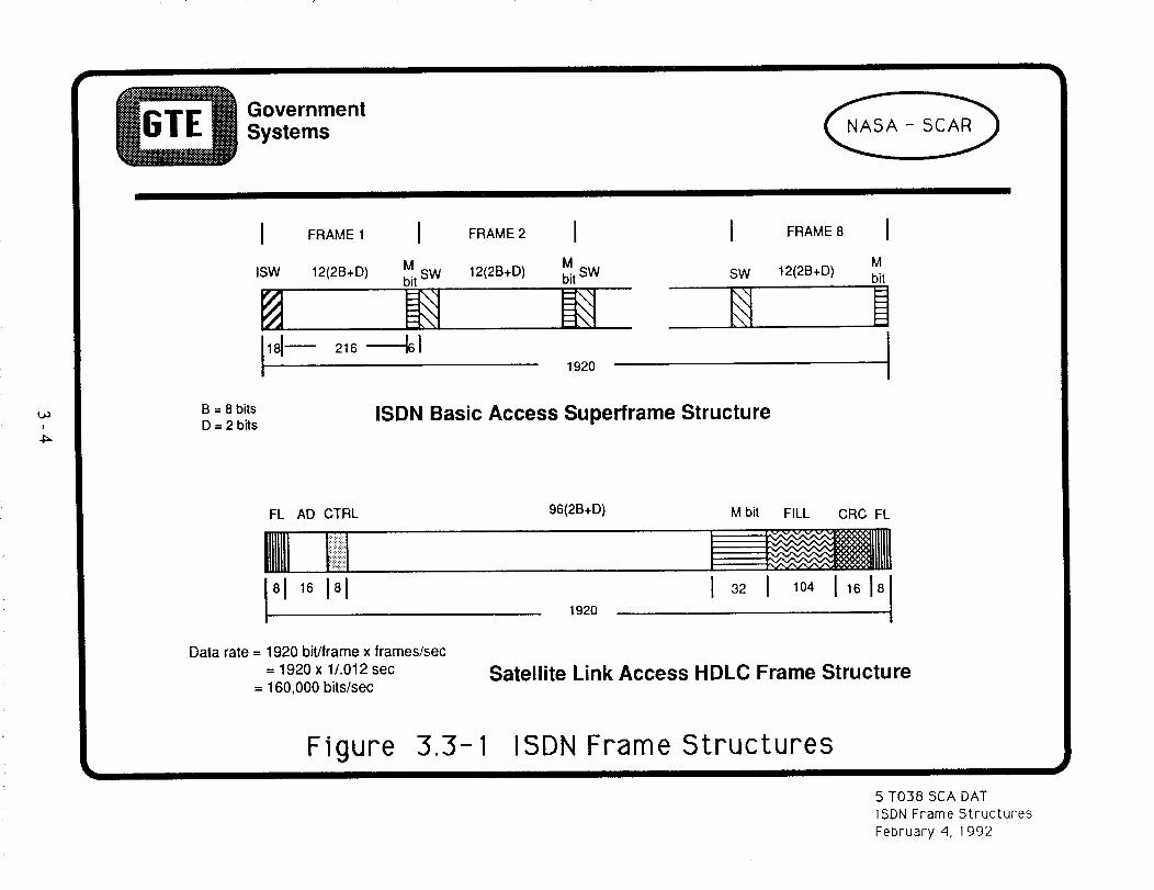
3.3 ISTA Frame Structures
Each side of the ISTA has its unique frame structure to accommodate their respective
protocols. Figure 3.3-1, "ISDN Frame Structures", shows both frame structures. TheISDN Basic Access Superframe Structure uses a format of 1920 bits. The transmissionacross the U-interface is organized into groups of eight 2B 1Q frames, called superframes.A frame consists of three fields:
Synchronization word (SW): Used for physical layer synchronization andframe alignment. It consist of a pattern of 18 bits.
User Data (12(2B+D): 12 groups of 2B and D information. Each groupcontains 8 B1 bits, 8 B2 bits, and 2 D bits resulting in 216 bits of user data.
Overhead Data: These bits are used for physical channel maintenance, error
detection and power status. A total of 6 bits are used per frame.
As shown in Fig 3.3-1 the inverted synchronization word (ISW) identifies the first frame inthe superframe; its is a pattern of 18 bits that is merely the inverse of the normalsynchronization word. The superframe organizes the 6 overhead bits of each frame into ablock of 48 bits
The satellite link access HDLC frame structure consists of the same 1920 bits apportioned
in a different manner. The eight frames of user information are combined into a singleframe of 1728 bits for the 96(2B+D). The overhead bits are collected into Flag, Control,CRC, M-bits and Fill. The fill is used to perform rate adaption between the terrestrial and
satellite protocols.
3-1

I
l.a
User Terminal p_
I U 'i°ISDN I Ii-l_ Interface.__l kb
Terminal IIINTllL "_1 ISTA
,' 'Jz>J Expanded
U J View V.35
Low Bit Rate
Terminal
(LBR-2)
D & Malnt
Channel I ACTS32kDps Signaling
SignalingHandler
Signaling I
Figure 3.ISDN
nter.face
. r i_iiiTerm Inatlon ii_!!ilL..pro.t°c°.L..iiiiiiiiii_;ii!I_II--,I _i_iiiii_;_iiii_;_ii_;i_;_!i_i_i_i_!_iiiiiiiii!i!iiiiiiiiiiii_!_i;_!_iii;i!iii_ii_iiiii__,i',i',!',!!i',i',ili',i':iii':i;i!!!i!i!i!iiiiiiii;iiii!!!i!i!!!i!ili
Potential
ImpleVlee ntatlon
MC145472
Adapter (ISTA)
1-1
Satellite Terminal
MC68302
M68000 I Int/Tlme_Core Controlle 1
_. i _oooI ._7 I 5ys B:,_ I "T,
Io_1 Iouo,-_o_II _a°°e't-_ _ I
i_ Serial I I PeripheralComm _ BUS
C°ntr°lle_ I ----.l Serial I_
i_ I 1 Comm r
Ser,a,k 21C°ntr°llerlComrn _
Controllel]3 [
MICRO
Comm
Controller
5 T038 SCA DAT
ISTA DiagramFebruary 4, 1992
HDLC
ToSatellite

I
_ overnmentSystems
v.35
IL ' I'"U" I HDLC iNT1 _ _ " LT" I PROCESSOR -'' riI
I
ISTA "CPE SIDE"
SATMODEM
L SAT IMODEM -F
V.35
II
v
IIII
i' i "U"
HDLC I "NT" =PROCESSOR I
II
ISTA "SWITCH SIDE" #5ESSISDN SWITCH
Figure 3.2- 1 ISTA Functional Block Diagram
5 T038 SCA DATISTA Funct Block DiagFebruary 4, 1992
!
O GovernmentSystems
I FRAME1I FRAME2IISW 12(2B+D) M M
bit SW 12(2B+D) bit SW
1920
I FRAME 8
SW 12(2B+D)
H
B = 8 bits
D = 2 bitsISDN Basic Access Superframe Structure
IM
bit
FL AD CTRL
gN
Data rate = 1920 bit/trame x trames/sec
= 1920 x 1/.012 sec
= 160,000 bits/sec
96(2B+D)
1920
M bit FILL CRC FL
Satellite Link Access HDLC Frame Structure
Figure 3.3-1 ISDN Frame Structures
5 T038 SCA DAT
ISDN Frame Structures
February 4, 1992
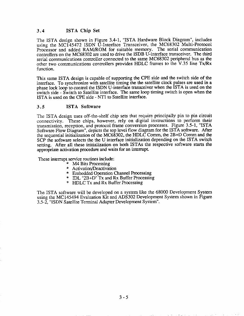
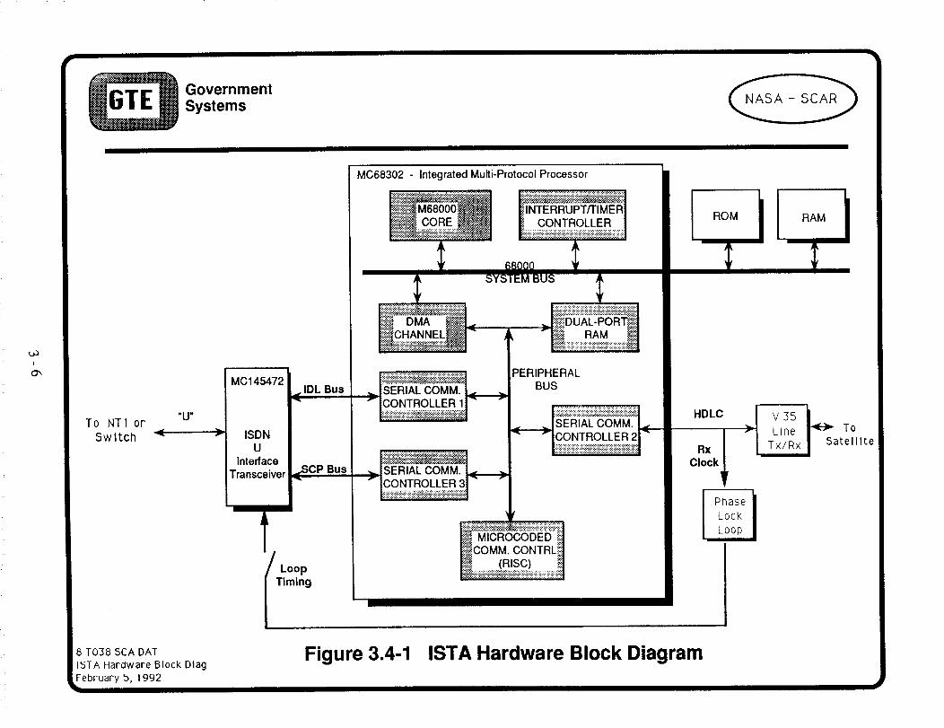
3.4 ISTA Chip Set
The ISTA design shown in Figure 3.4-1, "ISTA Hardware Block Diagram", includes
using the MC145472 ISDN U-Interface Transceiver, the MC68302 Multi-ProtocolProcessor and added RAM/ROM for suitable memory. The serial communicationcontrollers on the MC68302 are used to drive the ISDB U-interface transceiver. The thirdserial communications controller connected to the same MC68302 peripheral bus as theother two communications controllers provides HDLC frames to the V.35 line Tx/Rxfunction.
This same ISTA design is capable of supporting the CPE side and the switch side of theinterface. To synchronize with satellite timing the the satellite clock pulses are used in aphase lock loop to control the ISDN U-interface transceiver when the ISTA is used on theswitch side - Switch to Satellite interface. The same loop timing switch is open when theISTA is used on the CPE side - NT1 to Satellite interface.
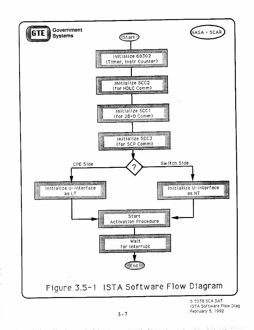
3.5 ISTA Software
The ISTA design uses off-the-shelf chip sets that require principally pin to pin circuit
connectivity. These chips, however, rely on digital instructions to perform theirtransmission, reception, and protocol frame conversion processes. Figure 3.5-1, "ISTASoftware Flow Diagram", depicts the top level flow diagram for the ISTA software. After
the sequential initialization of the MC68302, the HDLC Comm, the 2B+D Comm and theSCP the software selects the the U interface initialization depending on the ISTA switch
setting. After all these initialization on both ISTAs the respective software starts the
appropriate activation procedure and waits for an interrupt.
These interrupt service routines include:* M4 Bits Processing* Activation/Deactivation
* Embedded Operation Channel Processing* IDL "2B+D" Tx and Rx Buffer Processing* HDLC Tx and Rx Buffer Processing
The ISTA software will be developed on a system like the 68000 Development System
using the MC145494 Evaluation Kit and ADS302 Development System shown in Figure3.5-2, "ISDN Satellite Terminal Adapter Development System".
3-5
L_I
O_
_ GovernmentSystems
"U"To NTI or
Switch
8 T038 SCA DAT
ISTA Hardware Block Dlag
February 5, 1992I
MC145472 I_ IDL Bus
IISDNU
_,scplnterfaceI Bus
MC68302 - Integrated Multi-Protocol Processor
i:.i:i_:.::.!:_iii.:_.._.:J":':':':':::""::::::::::::::::::::::::::::::::
:::_<_ "::_:._
[-"i_C HAN NEL__._;.:_.:_:_:_:_.-;_i_:_.:_::::::::::::::::::::::::::::::::::::::::::::
:iSi$!:i:i:i3:i:i:_$i:i:_:i:i:i8i:i:i:!:i:_ii:iii:ij j::::i';:iiiii::.i':.:i:
INTERRUPT/TIMERCONTROLLER
_i_ii!i!_ii_!_i!_!!i!-_ii!ii-<'_ij!_ii!ii!ii!i;!iij:.ii_.-'ii-'iij.:_.:i.:i_iii'iiii!ii
68000
SYSTEM BUS I
!!iii;:_iUAL_p_i!iii_:::<:<::<:: :<<<<.:<.::..;<.;.:<<...:.>:.:<<<.:.
' _N RAM
:i:i:i:i:i:i:i:i:i:i:i:2_:_"":':::i:i:i:.::?--i:'::j:i:i:i:_-'.::'_:
,,._|SERIAL COMM.
,v tCONTROLLE R 11- -
",--ISERIAL COMM.
PERIPHERALBUS
_f
_. MICROCODED _:;]COMM. CONTRL!I1
lii_ (R_SC)i!l|_i;ii;iiiii;i_ii;:i_:i_:_i_._i!i!iiiii::iii_iii_ii.ii_iiiii_i_i;ii!!i;!;ii_.|
HDLC
Clock
Phase /
Lock I
I V35 I_ 57- Line To
Tx/Rx atelllte
Figure 3.4-1 ISTA Hardware Block Diagram
Government
Systems
Initialize 68302(Timer, Instr Counter)
Initialize SCC2(for HDLC Comm)
Initialize SCCl(for 2B+D Comm)
Initialize SCC3(for SCP Comm)
CPE Side Switch Side
Initialize U-Interfaceas LT
StartActivation Procedure
Initialize U-Interfaceas NT
_JWait
for Interrupt
Figure 3.5- 1 ISTA Software
3-'/
Flow Diagram
5 T038 SCA DATISTA Software Flow DiagFebruary 5, 1992

i
oo
_ GovernmentSystems
MC145494 Evaluation Kit
I.=-=- I
2B1Q "U"
TO V.35
TRANSCEIVER
ADS302 Development System
68000 Development System
Figure 3.5-2 ISDN Satellite Terminal Adapter Development System
5 T038 SCA DAT
ISTA Development System
February 5, 1992

SECTION 4
ISTA Activation Diagrams
4.1 Introduction
Before meaningful ISDN communication services can be provided through the satellite,each ISTA must be activated with the proper protocol sequence in conjunction with its
counter part ISTA at the other end. In that context, activations can be viewed as beinginitiated by either the exchange or initiated by the equipment.
4.2 ISTA Activation Initiated by the Exchange
Figure 4.2-1, "Total Activation Initiated by the Exchange", shows the sequence ofprotocols initiated by the exchange and the responses that will permit the ultimatecommunication of ISDN user traffic. The Z-chart of these protocol sequences is aligned
with a top level block diagram of the satellite connectivity between the ISDN switch andthe terminal equipment (TE). The exchange begins the activation process from its null statewhen it receives an activation request (AR) protocol message. The switch LT changes itsstate to activation proceeding (AP) and sends an activation request to its local ISTA,NT>ISTA, which immediately sets its state to the AP state. The AR protocol messagereceived by the NT section of the ISTA converts the digital AR message into control bits inthe HLDC frames that are continually being sent through the communications satellite to theother ISTA, SAT>LT, and sets its state to AP. The NT>SAT ISTA begins the exchange of
synchronizing information with the LT at the Exchange.
Meanwhile the HDLC protocols with the set control bits are received by the SAT>LT ISTAwhich sets its state to AP and begin exchanging synchronizing information with the userterminars NT. That NT also sets its state to AP. The superframe synchronization (SS) onthe each side of the satellite results in both the exchange-LT and the equipment -NT being
set to the SS along with their corresponding ISTAs. The user-NT sends an Info2 messageindicating it is ready to receive user data as Info3. The proper reception of Info3 sets thestates of all the interfaces to activated (act=l) along the way and an activation indication(AI) state is entered. The timely response to an Info3 message by an Info4 message keeps
all the interfaces synchronized for continuous information flow.
4.3 ISTA Activation Initiated by the Terminal Equipment
Figure 4.3-1, "Total Activation Initiated by Terminal Equipment", shows the sequence ofprotocols initiated by the exchange and the responses that will permit the ultimatecommunication of ISDN user traffic. The Z-chart of these protocol sequences is aligned
with a top level block diagram of the satellite connectivity between the ISDN switch andthe terminal equipment (TE). The terminal equipment begins the activation process from itsnull state by receiving an activation request (AR) protocol message in the form of Infolfrom the terminal equipment. The protocol exchange process continues in the same fashionas described above until all interface states are in the activated state (act=l), signaling
activation indication (AI), and a superframe synchronized flow of information is flowing interms of Info3 and Info4.
4-1

_661 '174JgnJqg:l g6ugqox3 _q UOIIgAIIOV J.V(]V3S g£O.L S
_03NI
_O:INI "-
J
;_O-INI
I.=1_
:OH_
L=lOe
_S
dV
IN
,====e _
g-IS
_NS
- _NS
_'-IS
NJ.
d
-11_
I.=1OE
L=IOIE=Ot_P
IV
IV
EIV
I
, (oq)i
l.=_el
dV
I:IN
r
t;NS
OU/,S -IS
I =oCls loe l!.q_ -
4
__dg'lS
LIS
LNS .,,_.
NL
"U.
J.VS-J.N
L=IOIE
IV
r
SS
_VI"I
LIN .n. .1i.
HOJ.IMS
NOSI
stueis s GlueuJUJeAO_)
c-qt
,d"
f

_ GovernmentSystems
ISDN
SWITCH
"U"
LT
SIA
NT-SAT
ISI,AI!I
SAT-LT
"U"
NT1
NT
TE
4_I
APJ
NR1 (b0) =1
NR1 (b3,bl,b0) =1
M40=1
_ct=l
TNJ
SL1
"---.---- SL2"_"
SN2
M bit act SL3.,8=="--"
NF
AR
NR;
NR1
act=l
M40=
act=l
2(b0)
NR1 (b3,bl
b3,bl ,b0) =1
AI
AI------_________:1
NR
AP
=Z)_I.J
act=l
act=l
!(bO):
N
-- SL1
- SL2 b
P
SL3
AR
12(b3'
NRli
act=l
M40=
act=l
INFO1
l(bO):1
INF02
b3,bl ,b0) =1
INFO3
INFO4,,.._
Figure 4.3-1 Total Activation Initiated by Terminal Equipment
5T038SCADAT Activation by Term Equip February 4, 1992

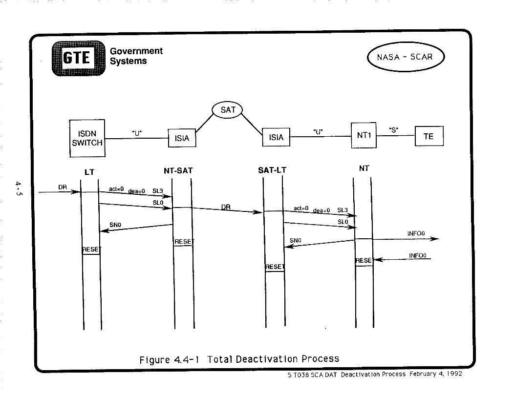
4.4 ISTA Deactivation Process
Figure 4.4-1, "Total Deactivation Process", shows the sequence of protocols initiated bythe exchange and the responses that will permit the deactivation of all the interfaces. The Z-chart of these protocol sequences is aligned with a top level block diagram of the satelliteconnectivity between the ISDN switch and the terminal equipment (TE). The LT on theexchange side receives a deactivation request (DR) that is passed along in term of statechanges, protocol messages, and reset at the interfaces Then at the terminal user end theNT1 and TE continue to exchange Info0 protocol messages.
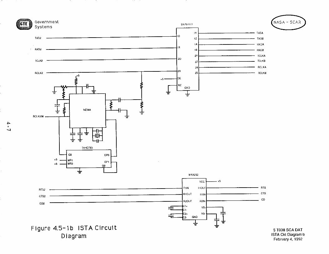
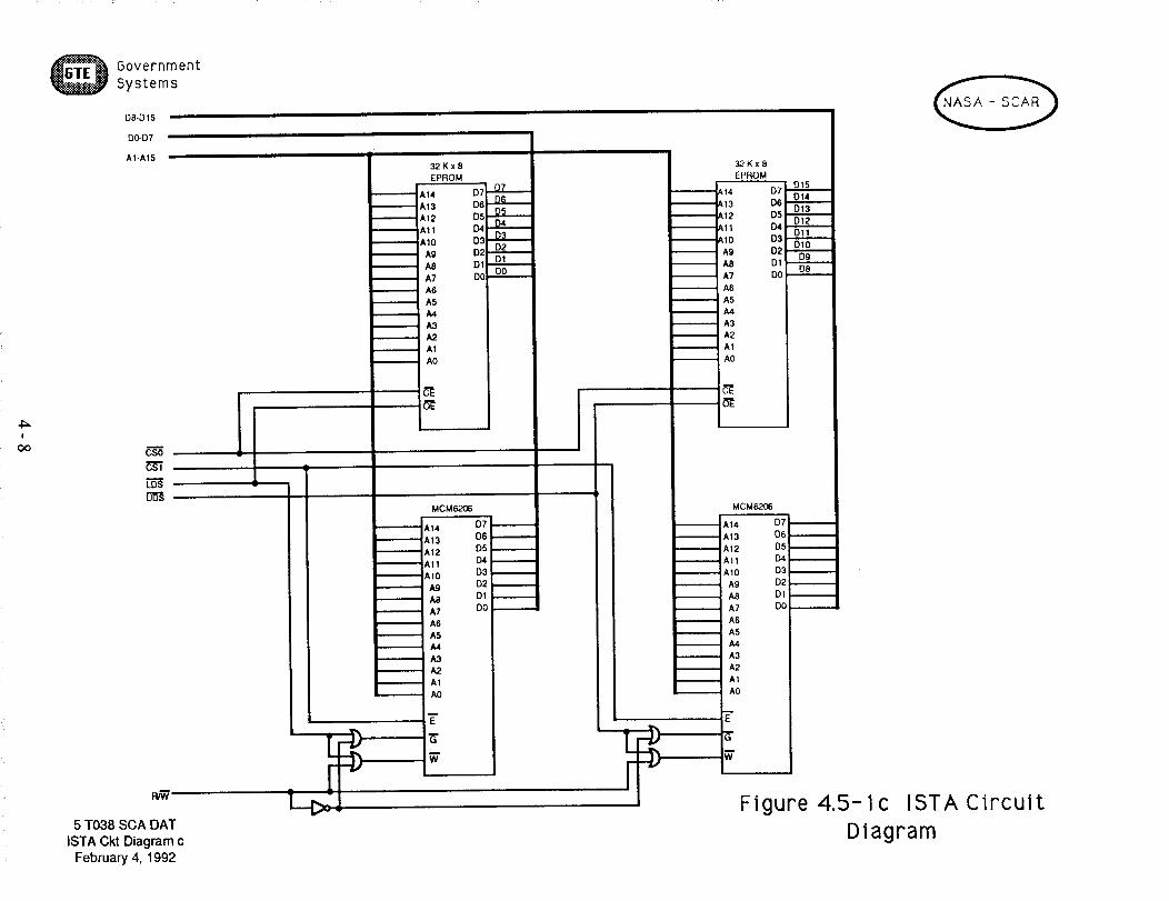
4.5 ISTA Circuit Diagram
The circuit diagram shown in Figure 4.5-la,b,c, "ISTA Circuit Diagram" shows the pin to
pin connections of the ISDN U-Interface Transceiver (MC145472), the Integrated Multi-Protocol Processor (MC68302), and the ancillary circuitry identified in the Figure 3.4-1.The specific component values will be addressed in the design reviews that will be part of
the implementation of these ISTAs.
4-4
_ GovernmentSystems
I
u_
DR
I ISDNSWITCH
LT
r
{ESE
"U"ISIA
NT-SAT
_ act=O d0a= 0 SL3
SNO
FIESE'
ISI,_
SAT-LT
:IESE7
"U"
act=0 dea=0 SL3
SLO
SNO
NTI
NT
:IESE
"S"
-_.d'
TE
INFO0
INFO0
Figure 4.4-I Total Deactivation Process
5TO38SCADAT Deactivation Process February 4, 1992

I
GovernmentSystems
O0
"_G3
;or =
_-_c_
r"m
--J=
RCLK256
1+_L_
I.J.._
+5 I
@w
N.C.
-l_L T
_.&.
MC145472
IDLM/S(L)
IDLCLK
(PIDLSYNC
SENSE P IDLTX
IDLRX
RXP SCPCLK
SCPTX
SCPRX
sCPEN(L)?,XN
RESET(L)
;ENSE N
IRQ(L)
TXN TX BAUD CLK
RxBAUD CLKVDD Tx
TEST 1
VSS Tx TEST 2
TEST3
VDD Rx TEST 4
TEST 5
VSS Rx TEST 6
7TEST
Vrel P TEST 8
Vret N TEST 9
TEST 10
:REQ SEL2 TEST 11
TEST 12
:REQ SELl TEST 13
;REQ SEL0 TEST 14
TEST 15
BUF XTAL TEST 16
FREQ REF TEST 17TEST 18
TEST 19
XTAL OUT VDD I/O
VSS I_3
VDD
XTAL IN VSS
VDD
VSS
VDD
_D OUT VSS
VDD
PLL CAP VSS
VDD PLL
SS PLL
Figure 4.5-1a ISTACircuit
Diagram
_+5 IDLCLK
IDLSYN
IDLTX
IDLRX
SCPCLK
r-
_qPT_
_CPRX
SCPENLT
RESET
IRQLT
_NC
_NC
_NC
_NC
_NC
_NC
_NC
_C _
NC_
NC_
NC_
NC_
NC ,=_-====,
NC _="=_=_
NC
ii-+5 ,5
_L+5 +5
MC68302
T1NI RXD2
.1CLK TXD2
1SYNC RCLK2
1RXD TCLK2
1TXD CTS2
RTS2;PCLK
CD2;PTXD
A23-A1E ISPRXD
A15PAT
A14
PA8 A13
IRQ1 A12
All
SDS1 A10
L1GR A9
L1RQ A8
BRG1 A7
A6
PAO-PA6 A5
A4
PA9 - PAl5 A3
PBO-PB2 A2
PB,4-PB11 AI
D15
D14
D13
D12
D11
IRC_ DIO
IRQ7 D9
D8
D7
D6
D5
AVEC [34
BUSW D3
BERR D2
BR D1
_lBe DOBGACK DTACK
FRZ BCLR
: )ISCPU ASUDS
LDS
RAN
CS0
CSl
CS24ALT
CS3
RESET RMC
_C
FCO-FC2
EXTAL XTALCLKO
RXD2
TXD2
RCLK2
TCLK2
CTS2
RTS2
CD2
-- NC
--NC
--NC
--NC
•i=_,,_, NC
A1-A15
, DO-D15
UDS
LDS
P_N
CS0
CS1
5 3"038SCA DATISTA Ckt Diagrama
February 4, 1992
4:=I
.,.,j
GovernmentSystems
TXD2
RXD2
TCLK2
RCLK2
RCLK256_
RT$2
CT$2
CD2
Figure
74HCT93
Q3 CP0
+5 MR1CP1
+5 MR2(30
t
4.5-1b ISTACircuit
Diagram
SN751177
1Y
ID
1Z
1A
1R
1B
2Y
2D
2Z
2A
2R2B
+5 _ DE
._"--- i RE
m
-"1_............._ _
GND
m
MAX232
VCC
TIIN TIOUI
RIOUT RIIN
R2OUT R21N
CI÷VS,,
C'I-
(;2* VS-
C2- GND
_l_
_÷5
TXDA
TXDB
RXDA
RXDB
TCLKA
TCLKB
RCLKA
RCLKB
RTS
CTS
CD
5 T038 SCA DAT
ISTA Ckt Diagram bFebruary 4, 1992
I
oo
GovernmentSystems
DB-D15
DO-D7
A1-A15
mcso
FuW
5 T038 SCA DAT
ISTA Ckt Diagram cFebruary 4, 1992
.,=,,.ii_,_
.=,ii...== d
m
m
I
J
32Kx8
EPROM
A14
A13
A12
All
A10
A9
A8
A7
A6
A5
A4
A3
A,2
A1
A0
MCM6206
A14 D7
A13 D6A12 D5iAll D4
AIO D3
A9 D2
A8 Ol
A7 DO
A6
A5
A4
A3
A2
A1
A0
-£
D7' D7D6 D6D5 D504 D4D3 D3
D2 O2'I"_"_DI DI,,_,_..._DO DO
m
m
m
32Kx8
EPROM
_A14
_A13
_AI2
_A11
IAIO
_, A9
_ A7_ A6_ A5i A4_ A3
_ A2
_ A1
_ AO
D15D7
D14[:)6
D13D5
D12D4
DllD3
D2 010D9
D1D8
I
m
m
m
m
m
m
i
m
m
I
MCM62£6
A14 D7
A13 D6 --
A12 D5
All [:).4 I
AIO D3
A9 D2
A8 D1 /
A7 DO
A6
A5
A4
A3
A2
A1
AO
7"
g-
Figure 4.5-1c ISTA Circuit
Diagram
SECTION 5
SUMMARY
5.1 General
This task completion report for the ISIS Hardware experiment design presented thecomplete end-to-end view from the basic objectives to the ISTA circuit design. The ISTAhardware design is applicable to the the Interim Service ISDN Satellite (ISIS) and can beused with any HDLC interfaced communications satellite. The ultimate aim of this aspectof the SCAR Program is to demonstrate that ISDN communications via satellite is possibleand to corroborate the engineering design values for new advanced ISDN communicationssatellite. The technical and operational parameters for this ISDN advancedcommunications satellite design will be obtained from an engineering software model of the
major subsystems of the ISDN communications satellite architecture. Discrete eventsimulation experiments will be performed with these ISIS models using various trafficscenarios, technical parameters, and operational procedures. The data from thosesimulations will be analyzed using the performance measures discussed in previous NASA
SCAR reports. These same data will be compared from data gathered from hardwareexperiments using ISTAs cited in this report.
5.2 Review
This task completion report begans by describing the objectives of the ISIS hardwareexperiment in terms related a communications satellite connected to an ISDN terrestrial link.A specific application of sending compressed video from NASA Lewis in Ohio to the GTE#5ESS switch in Virginia was postulated for discussions about the design of the ISTA.
The ISTA design was decomposed into several detailed views identifying the designrefinements along the way. Each of these design views was described in terms of theirassociated hardware, the chip set, and the software design. The ISDN basic accesssuperframe structure and the satellite link access HLDC Frame Structure were describeddown to the bit level.
The ISTA activation and deactivation for both the exchange and terminal equipment was
discussed in the context of end-to-end Z-diagrams. The relationship between the 68000Development System and the ISTA was shown and a detail circuit design down to the chip
pin connections was provided.
5.3 Continuing Efforts
The design of the ISTA is completed. A subcontractor with prior expertizes with thisSCAR program has contracted to build three ISTAs suitable for experiments with ACTS orother communications satellites. Experiments will be conducted to verify the performanceof the ISTA and to demonstrate the proof of concept. The experiment configuration willinclude ISDN terminals, ISTAs, the ISDN hub switch and, optionally, the ACTS/TDMA
simulator. An ISDN protocol emulator/analyzer will be used to verify protocolconformance of the ISTA interfaces. The ACTS/TDMA hardware simulator could be used
to augment ISTA testing. The ACTS/TDMA simulator would provide a hardwaresimulation of ACTS call processing procedure, processing delays, and switching delaysand would help the team to undertake more advanced ISDN communications tests.
Experiments are expected to include ISDN call applications such as voice call management,video conference, and Group IV facsimile transmission in addition to various passive bus
configurations.
5-1