intermediate representations in imperative compilers: a survey
TRANSCRIPT

26
Intermediate Representations in Imperative Compilers: A Survey
JAMES STANIER and DES WATSON, University of Sussex
Compilers commonly translate an input program into an intermediate representation (IR) before optimizingit and generating code. Over time there have been a number of different approaches to designing andimplementing IRs. Different IRs have varying benefits and drawbacks. In this survey, we highlight keydevelopments in the area of IR for imperative compilers, group them by a taxonomy and timeline, andcomment on the divide between academic research and real-world compiler technology. We conclude thatmainstream compilers, especially in the multicore era, could benefit from further IR innovations.
Categories and Subject Descriptors: D.3.4 [Programming Languages]: Processors—Compilers, Optimiza-tion, Retargetable compilers
General Terms: Languages, Performance
Additional Key Words and Phrases: Compilers, intermediate representations, optimization
ACM Reference Format:Stanier, J. and Watson, D. 2013. Intermediate representations in imperative compilers: a survey. ACMComput. Surv. 45, 3, Article 26 (June 2013), 27 pages.DOI: http://dx.doi.org/10.1145/2480741.2480743
1. INTRODUCTION
Compilers are an essential tool in software development. Without compilers, we wouldnot have efficient support for the wide variety of expressive high-level programminglanguages available today. Better compilers have allowed for more powerful program-ming languages, raising the level of abstraction for the programmer and making codeeasier to write. However, compilers do more than just translating source code into tar-get code. They are also able to optimize the source program in order to make it better bysome criteria. For example, the user may want the smallest code possible or the fastestcode. Since compilers can (and should) optimize code, it makes sense to translate thesource program into a data structure which makes optimization easier.
A compiler commonly constructs an intermediate representation (IR) [Aho et al. 2006],which is an internal form of a program created during compilation [Tremblay andSorenson 1985]. This structure forms the start and end point of a number of analysesand transformations performed during compilation. Many compilers use more thanone IR during the course of compilation [Torczon and Cooper 2007].
The course of compilation is as follows. Figure 1 shows a typical compiler structureas a number of phases. To begin with, the source program is read into the compilerand split into its atomic syntactic components by the lexical analyzer. These syntacticcomponents are called tokens and are passed to the syntax analyzer, where their orderis inspected against a formal definition of the language to ensure the source program
J. Stanier is supported by a studentship from the EPSRC.Authors’ address: J. Stanier and D. Watson, School of Informatics, University of Sussex, Falmer, Brighton,BN1 9QJ, UK.; corresponding author’s email: [email protected] to make digital or hard copies of part or all of this work for personal or classroom use is grantedwithout fee provided that copies are not made or distributed for profit or commercial advantage and thatcopies show this notice on the first page or initial screen of a display along with the full citation. Copyrights forcomponents of this work owned by others than ACM must be honored. Abstracting with credit is permitted.To copy otherwise, to republish, to post on servers, to redistribute to lists, or to use any component of thiswork in other works requires prior specific permission and/or a fee. Permissions may be requested fromPublications Dept., ACM, Inc., 2 Penn Plaza, Suite 701, New York, NY 10121-0701 USA, fax +1 (212)869-0481, or [email protected]© 2013 ACM 0360-0300/2013/06-ART26 $15.00
DOI: http://dx.doi.org/10.1145/2480741.2480743
ACM Computing Surveys, Vol. 45, No. 3, Article 26, Publication date: June 2013.

26:2 J. Stanier and D. Watson
Lexical analyzer
Syntaxanalyzer
Semanticanalyzer
Optimization passes
Codegenerator
character stream
tokenssyntax
tree IR IRtarget-machine
code
Fig. 1. A typical compiler structure split into phases.
is syntactically correct. Typically a syntax tree and symbol table are produced by thisstage, and these data structures are used by the semantic analyzer to perform typechecking and type conversions, amongst other analyses concerned with correctness.After this stage, the IR is generated. The IR can then be used to perform a numberof analyses and transformations to improve the program. Then, the target machinecode is generated from the IR. The front-end of a compiler is considered to be allphases before optimization on the IR, that is, the lexical analyzer, syntax analyzer,and semantic analyzer. The back-end is commonly considered to be all phases aftermachine-independent optimization: namely all stages of code generation.
The IR is not just present to act as a vehicle for code optimization. It can play akey role in compiler implementation, where front-ends (for different source languages)and back-ends (for different target architectures) can share a common IR, resultingin a significant reduction of effort when implementing multiple compilers. This ideahas existed since Conway [1958], but it has never been implemented for all sourcelanguages and target architectures, although the use of a common IR for a small rangeof similar programming languages is not uncommon.
Currently, there are a wide variety of different IRs in use, both in the literature andin real-world compilers. Different IRs are used for different purposes, and each has itsown benefits and drawbacks. The first objective of this article is to provide a detailedoverview of the IR landscape for imperative compilers. To accomplish this, we proposean IR taxonomy then identify the components and design purposes of different IRs andgroup them accordingly. The second objective is to look at the size of the technology gapbetween academic or commercial research and real-world compilers in terms of theirIRs. We do this by providing a timeline of IR developments in research and surveyingthe IR technology used in current compilers. We are unaware of any survey of IRs,apart from two existing bibliographies [Chow and Ganapathi 1983; Ottenstein 1984].
Section 2 outlines some terms and definitions we will be using in this article. InSection 3, we outline our taxonomy. Section 4 looks at what we call linear IRs, thatis, those that are text-based pseudoinstructions for an abstract machine. Section 5looks at what we call graphical IRs, that is, those that are represented as a graph.The categorization of linear versus graphical IRs is not perfect, and in many cases,compilers use components of both. However, we divide them in this way to better showtheir features. Section 6 classifies the IRs, explores the difference between IR usagein academia and real-world compilers, and comments on how IR choice is importantdepending on the compilation goal. Section 7 concludes.
2. TERMS AND DEFINITIONS
Before we present our taxonomy, we will outline some terms and definitions that areused repeatedly throughout this paper. First, we frequently refer to the definition ofa directed graph, which is an ordered pair G = (V, E) comprising of a set V of nodesand a set E of edges, where E ∈ V × V . Many IRs are represented as graphs. A pathfrom a vertex v0 to vn in a graph is a sequence of nodes v0, v1, . . . , vn−1, vn which all areconnected by edges in E. If a path v0, . . . , v0 exists in E, then the graph has a cycleand is therefore called cyclic. If no such path exists, the graph is acyclic [Biggs 1993].
ACM Computing Surveys, Vol. 45, No. 3, Article 26, Publication date: June 2013.

Intermediate Representations in Imperative Compilers 26:3
Fig. 2. Some example code containing an if statement and a while loop.
A strongly connected component of a graph is a subgraph in which all nodes in thesubgraph are reachable by all other nodes in the subgraph. A back edge in a directedgraph is one that points to an ancestor in a depth-first traversal. A bipartite graphis a set of graph nodes, which when decomposed into two disjoint sets, no two graphnodes within the same set are adjacent. Single-entry, single-exit (SESE) analysis findssubgraphs of a directed graph that have exactly one incoming edge and one outgoingedge.
We also refer to dependence relationships in programs. The first of these is controldependence. Control dependence arises from execution order constraints within theprogram. For example, consider the code fragment in Figure 2. Here, the value thatis assigned to z is control-dependent on the outcome of the if statement guard: if itevaluates to true, then z = e, else z = f. Similarly, the value assigned to x is control-dependent on the while loop guard: if it evaluates to true, then the loop iterates settingx = a * d, else it stops iterating and no more assignments to x occur. The second isdata dependence. This arises from the flow of data in the program. In Figure 2, thestatement x = a * d has a data dependence on the previous statement a = b + c,since the latter must execute for the result of a to be available for the execution of theformer. Related to data dependence, a def-use chain for a variable connects a definitionof that variable to all of the uses it may reach.
We also refer to whether a program exhibits reducible control flow. If a program doesnot have reducible control flow, then it is irreducible. Irreducible programs preventcompilers from optimizing loops. Given a directed graph, it is reducible if we canrepeatedly perform transformations T1 and T2 until the graph has been transformedinto a single node. The resulting graph is called the limit graph. Assuming we areanalyzing a directed graph G, the transformations are as follows.
—T1 Suppose n is a node in G with a self-loop, that is, an edge from n to itself. Trans-formation T1 on node n is the removal of this self-loop.
—T2 Let n1 and n2 be nodes in G such that n2 has the unique direct ancestor n1, and n2is not the initial node. Then transformation T2 on node pair (n1, n2) is merging nodesn1 and n2 into one node, named n1/n2, and deleting the unique edge between them[Hecht and Ullman 1972].
These transformations are confluent: the same limit graph will be reached regardlessof the order of application. If there is more than one node in the limit graph, the CFGis said to be irreducible.
Trees are data structures that feature often in compilation. A tree consists of oneor more nodes. Exactly one node is the root of the tree. All nodes except the root haveexactly one parent; the root has no parents. Edges connect parents to children. A nodewith no children is called a leaf. Nodes with one or more children are called interior
ACM Computing Surveys, Vol. 45, No. 3, Article 26, Publication date: June 2013.
26:4 J. Stanier and D. Watson
Structure Dependence ContentLinear None Full
Graphical (cyclic) Control PartialGraphical (acyclic) Data
Hybrid
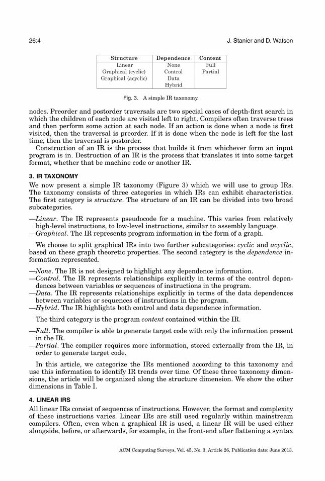
Fig. 3. A simple IR taxonomy.
nodes. Preorder and postorder traversals are two special cases of depth-first search inwhich the children of each node are visited left to right. Compilers often traverse treesand then perform some action at each node. If an action is done when a node is firstvisited, then the traversal is preorder. If it is done when the node is left for the lasttime, then the traversal is postorder.
Construction of an IR is the process that builds it from whichever form an inputprogram is in. Destruction of an IR is the process that translates it into some targetformat, whether that be machine code or another IR.
3. IR TAXONOMY
We now present a simple IR taxonomy (Figure 3) which we will use to group IRs.The taxonomy consists of three categories in which IRs can exhibit characteristics.The first category is structure. The structure of an IR can be divided into two broadsubcategories.
—Linear. The IR represents pseudocode for a machine. This varies from relativelyhigh-level instructions, to low-level instructions, similar to assembly language.
—Graphical. The IR represents program information in the form of a graph.
We choose to split graphical IRs into two further subcategories: cyclic and acyclic,based on these graph theoretic properties. The second category is the dependence in-formation represented.
—None. The IR is not designed to highlight any dependence information.—Control. The IR represents relationships explicitly in terms of the control depen-
dences between variables or sequences of instructions in the program.—Data. The IR represents relationships explicitly in terms of the data dependences
between variables or sequences of instructions in the program.—Hybrid. The IR highlights both control and data dependence information.
The third category is the program content contained within the IR.
—Full. The compiler is able to generate target code with only the information presentin the IR.
—Partial. The compiler requires more information, stored externally from the IR, inorder to generate target code.
In this article, we categorize the IRs mentioned according to this taxonomy anduse this information to identify IR trends over time. Of these three taxonomy dimen-sions, the article will be organized along the structure dimension. We show the otherdimensions in Table I.
4. LINEAR IRS
All linear IRs consist of sequences of instructions. However, the format and complexityof these instructions varies. Linear IRs are still used regularly within mainstreamcompilers. Often, even when a graphical IR is used, a linear IR will be used eitheralongside, before, or afterwards, for example, in the front-end after flattening a syntax
ACM Computing Surveys, Vol. 45, No. 3, Article 26, Publication date: June 2013.

Intermediate Representations in Imperative Compilers 26:5
Table I. Classification of IRs According to the Taxonomy of Figure 3
IR Structure Dependence ContentPolish Notation Linear None PartialExtended Polish Linear None FullTriples/Quadruples Linear None Partial3AC Linear None FullSSA Linear Data PartialGSA Linear Data FullAST/Parse Tree Graphical (acyclic) None FullDAG Graphical (acyclic) Data FullCFG Graphical (cyclic) Control FullSuperblocks Graphical (cyclic) Control FullSSA Graph Graphical (cyclic) Data PartialDFG Graphical (cyclic) Data PartialPDG Graphical (cyclic) Hybrid FullPDW Graphical (cyclic) Hybrid FullVDG Graphical (cyclic) Data FullVSDG Graphical (acyclic) Data FullClick’s IR Graphical (cyclic) Hybrid FullDependence Flow Graph Graphical (cyclic) Data Full
tree or in the back-end before code generation. Linear IRs can also be contained withingraphical IRs, such as the control flow graph, as we will see later.
In the early days of compilation, many linear IRs were developed as part of com-mercial or unpublished software, so the exact original specifications are not alwaysavailable. We summarize these under classical representations.
4.1. Classical Representations
One of the earliest forms of linear IR was based on Polish notation. This was originallydeveloped as a parenthesis-free mathematical notation [Eukasiewicz 1957] and existsin prefix and postfix forms. This notation was used in a number of early compilers. Theexpression
(1 + 2) ∗ 3
can be represented in prefix notation in the following way.
* + 1 2 3.
Alternatively, it can be represented in postfix notation as
1 2 + 3 *.
Postfix Polish notation has been used as it is an efficient IR for generating codefor a stack-based machine architecture (e.g., Burroughs mainframe computers [Barton1961]). To generate code, the IR is simply scanned left to right, with operands beingplaced on to the stack sequentially and operators being applied immediately to theoperands on the stack. Since computer programs contain non-arithmetic operations,extended Polish [Stauffer 1978] describes any extension of Polish notation that canhandle additional operations, such as conditional branching, loops, and assignment.All Polish notation statements are referenced by their position in the execution or-der. Although Polish notation-based IRs are compact, they are difficult to optimize.Additionally, most modern processors use register-based rather than stack-based ar-chitectures. Construction of prefix Polish notation can be achieved by a linear preorder
ACM Computing Surveys, Vol. 45, No. 3, Article 26, Publication date: June 2013.
26:6 J. Stanier and D. Watson
walk of the abstract syntax tree (Section 5.1). Construction of postfix Polish notationinvolves a postorder walk.
Another classical IR is based on triples [Aho et al. 2006]. These instructions havethree fields: an operator op and two arguments a1 and a2, represented as <op, a1, a2>and also referenced by position. The expression (1 + 2) ∗ 3 would be represented by twotriples, where the parenthesized numbers in the a1 or a2 fields refer to the position ofanother triple as an operand.
(0) <+, 1, 2>;(1) <∗, (0), 3>.
Quadruples extend triples by having four fields: an operator op, two arguments a1and a2, and a result r, represented as <op, a1, a2, r>. The result field r stores the resultof the instruction. (1 + 2) ∗ 3 would be represented as follows.
<+, 1, 2, t0>;<∗, t0, 3, t1>.
Similarly, three-address code (3AC) is a linear IR consisting of a sequence of in-structions where there is at most one operator on the right-hand side of an instruc-tion. For example, the expression (1 + 2) ∗ 3 would have to be represented by two 3ACinstructions, as there are two operators. This is shown as
t0 = 1 + 2;t1 = t0 ∗ 3,
where t0 and t1 are temporary variables generated by the compiler. It is possible torepresent whole program information using 3AC. Aho et al. [2006] specify a 3AC formthat supports assignments, operations, jumps, procedure calls, array indexing, andaddress and pointer assignments. Triples, quadruples, and 3AC can be generated froma linear inorder walk of the abstract syntax tree.
Many modern compilers use some kind of linear instructions as an IR, either aloneor as part of a graph-based IR (Section 5). For example, the popular open-source LLVMcompiler [Lattner and Adve 2004] uses 3AC written as pseudo-assembly instructions,and the Java language uses Java bytecode [Lindholm and Yellin 2005] as a linear IRfed to the Java virtual machine. Register Transfer Language [Davidson and Fraser1980] is a linear IR close to assembly language that has appeared in many compilers,including GCC.1 These linear IRs support modularity in compiler design, allowing for aclean separation between phases. Some compilers may use high-level languages, suchas C, as do IRs also. The choice of linear IR can be highly dependent on the instructionset architecture (ISA) that is being generated. For example, if a compiler was beingwritten for a stack-based machine, then an IR like postfix Polish notation would beadvantageous. However, on the x86 ISA, a linear IR, such as a three-address code,would be easier to translate across into target code.
Some compilers use multilevel IRs. Here, a linear IR such as 3AC is used in multiplestages. The first stage is often very close to an abstract machine or a high-level lan-guage. Then, the compiler lowers the IR closer to the target machine code with everystep. The last level before machine code is often very close to the machine code itself. Al-though this strategy contains more optimization stages than just using one IR, it givesthe compiler more opportunity to exploit both high-level and low-level optimizationsalong the optimization pipeline.
1http://gcc.gnu.org.
ACM Computing Surveys, Vol. 45, No. 3, Article 26, Publication date: June 2013.

Intermediate Representations in Imperative Compilers 26:7
Fig. 4. Transformation of Figure 2 into SSA.
4.2. Static Single Assignment
Static single assignment form (SSA) [Cytron et al. 1991] is widely used as an IRin compilers today. It could be seen as a variant or property of other IRs, such aspreceding the linear IRs; however, it is in such widespread use in mainstream andacademic compilation that we consider it to be a separate entity. The linear IRs above donot explicitly show any dependence information. Many compiler optimizations requireknowledge of the data dependences in a program. SSA is a method that transformslinear IR variables to ensure that each is only assigned to once. SSA is not a language,it is a technique that can be applied to a linear IR. This allows for data-dependenceinformation to be easily discovered, since each use of a variable points to the exactdefinition. It does this by transforming each variable V into a variable Vi, which onlyhas one assignment. The most recent Vi variable is said to be the most dominatingand is always used in a given reference to the variable V . SSA uses pseudo-assignmentto handle points in the program where control flow merges. If some assignment to Vis dependent on a preceding choice in control flow, such as an if statement or loop,then a φ-function is used. This function will create a new definition of V depending onthe control flow path taken. We transform our sample code from Figure 2 into SSA inFigure 4. Since x is assigned to in the loop, a φ-function specifies that the most recentvalue of x here may be either the original value x1 if no iteration occurs, or the valuex3 if iteration does occur. Also, as z is assigned to in the if statement, a φ-functiongenerates z3 for the use in the following assignment to y1.
SSA explicitly shows the data dependence relationship between uses of a variable.Since SSA is in single assignment form, there cannot be any redefinition of a variable.Converting to SSA form makes various optimizations easier and more powerful, suchas global value numbering [Rosen et al. 1988] and constant propagation [Wegman andZadeck 1991]. The intuition as to why these optimizations are made easier is that byrenaming variables with subscripts, it is easy to see where the previous redefinition ofthat variable is. By converting into SSA form, reaching definition analysis is implicit byobservation. SSA can be used in conjunction with any other IR containing linear state-ments. Converting to SSA before doing a flow-insensitive analysis recovers a certainamount of flow-sensitivity.
Construction of SSA form involves two steps: φ-functions being inserted at join nodesin the control flow graph (Section 5.3), and new variables Vi being generated. Cytronet al. [1991] show that SSA can be constructed in O(R), time, where R is the maximumof N, the number of nodes in the control flow graph, E, the number of edges, Aorig, thenumber of original variable assignments, and Morig, the number of original mentionsof a variable. However, this construction technique can result in unnecessary φ-nodes
ACM Computing Surveys, Vol. 45, No. 3, Article 26, Publication date: June 2013.

26:8 J. Stanier and D. Watson
being inserted, and it was later shown to produce incorrect results in some situations.Bilardi and Pingali [2003] presented an algorithm that only computes the necessaryφ-functions and competes with the speed of Cytron et al.
SSA form cannot be directly interpreted in order to generate code. Therefore itmust be destructed before compilation can continue. This involves using an algorithmthat converts φ-functions into appropriately-placed copy instructions. The intuition, asgiven by Briggs et al. [1998] is as follows. To replace an φ-function referring to a variablen in a basic block b (Section 5.3), an algorithm inserts a copy operation into each of b’spredecessors. The copy moves the value corresponding to the appropriate φ-functionparameter into n. The number of copy instructions, and hence memory usage in thegenerated code, increases as the number of φ-functions increases. Briggs et al. [1998]showed that the original algorithm for SSA destruction produced incorrect results insome situations and presented a new, correct algorithm. Sreedhar et al. [1999] producedan algorithm that reduced the number of generated copy instructions. Boissinot et al.[2009] revisit the problem of destructing SSA form, improving on speed and memoryusage. SSA is a well-studied IR and is used in a number of mainstream compilers, suchas GCC and LLVM.
4.3. Gated Single Assignment
In SSA form, φ-functions are used to identify points where variable definitions con-verge. However, they cannot be directly interpreted as they do not specify the conditionwhich determines which of the variable definitions to choose. Thus, after SSA has beenconstructed and used for optimizations, it must be destructed before code generationcan begin. Gated single assignment [Ballance et al. 1990] replaces φ-functions withgating functions. These gating functions are used to represent conditional branchesand loops. GSA can be directly interpreted without having to perform any destructiontechniques, as is necessary in the case of SSA. We take our definition of the gatingfunctions from Tu and Padua [1995].
—The γ function explicitly represents the condition which determines which φ value toselect. A γ function is of the form γ (P, V1, V2), where P is a predicate, and V1 and V2are the values to be selected if the predicate evaluates to true or false, respectively.This can be read simply as if-then-else.
—The μ function is inserted at loop headers to select the initial and loop-carried values.A μ function is of the form μ(Vinit, Viter), where Vinit is the initial input value for theloop, and Viter is the iterative input. φ-functions at loop headers are replaced with μfunctions.
—The η function determines the value of a variable when a loop terminates. A η functionis of the form η(P, Vfinal), where P is a predicate and Vfinal is the definition reachingbeyond the loop.
We show our example code in Figure 2 translated into GSA in Figure 5. Here, thevariables are subject to the same renaming as in SSA. However, the loop uses the μfunction at the loop header to determine between the initial and iterative value of x,and the η function at the end of the loop to determine the loop exit value, based on adirect reference to predicate P1, which explicitly records the control choice in the loop.Also, the assignment to z3 is represented as a γ function rather than an φ function.The γ function has a direct reference to the predicate P2 that decides the control choicein the if statement, along with the choice between z1 and z2 that exists in SSA form.Typically, GSA form is used in conjunction with a graphical IR, such as the control flowgraph (Section 5.3). After the original publication, Campbell et al. [1993] further refinedthe representation, giving more explanation on the context and applications of GSA. Italso fixed initial shortcomings with regards to loops and complications on loop exits.
ACM Computing Surveys, Vol. 45, No. 3, Article 26, Publication date: June 2013.

Intermediate Representations in Imperative Compilers 26:9
Fig. 5. Transformation of Figure 2 into GSA.
Construction of GSA is used as an intermediate step in the construction of the pro-gram dependence Web (Section 5.8), where an SSA form program dependence graph(PDG) (Section 5.7) is translated to a GSA form PDG. This step takes O(VN2) oper-ations, where V is the number of variables in the program and N is the number ofnodes in the PDG’s control dependence graph. Interpreting GSA in this situation is notdiscussed in detail.
Thinned-GSA [Havlak 1994], a more compact version of GSA, has been used toperform value numbering. Construction of thinned-GSA is shown to take linear timefrom SSA form. Destruction is not discussed in this article. When GSA is used inconjunction with a graphical IR, destruction is similar to SSA destruction. When itis used alone, destruction is more complicated. Tate et al. [2011] give a destructionalgorithm for a similar IR which we believe would be adaptable to GSA. A formalsemantics of improved monadic GSA is introduced and used to validate compilationpasses in LLVM [Tristan et al. 2011]. Coq proofs show semantic equivalence betweenthese compilation passes.
5. GRAPHICAL IRS
Graphical IRs use nodes and edges to represent a variety of different relationshipswithin a program. Some of the earliest recorded graphical IRs are trees, directed acyclicgraphs, and flowgraphs. Often, a combination of a linear and graphical IR is used, forexample, instructions in SSA form can be contained within a flowgraph.
5.1. Trees
After lexical analysis and during syntax analysis of the source program, a compiler willcommonly generate some form of tree which represents the syntactic structure of theprogram. There are generally two types of tree which may be constructed: the abstractsyntax tree (AST) and the parse tree. ASTs differ from parse trees, as the interiornodes represent only the essential programming constructs rather than nonterminalsin the grammar for the input language. Given some expression, each AST interior noderepresents an operator, and the children of that node represent the operands of thatexpression. For example, assume the following expression language grammar in EBNF.
E = T {"+" T} | T.T = P {"*" P} | P.P = a | b | c.
ACM Computing Surveys, Vol. 45, No. 3, Article 26, Publication date: June 2013.

26:10 J. Stanier and D. Watson
(a) AST (b) Parse tree
Fig. 6. The sentence a * b + c represented as two different tree types.
Fig. 7. DAGs for the expression (a + b) ∗ (b + a) ∗ (c + d), showing both left-associativity and right-associativity.
Given the sentence a * b + c derived from this grammar, we can show the AST andparse tree in Figure 6. Notice that the AST only contains the essential information(the + and * operators and variable names), whereas the parse tree contains all of thenonterminals used in the parse. Syntax tree or parse tree construction is straightfor-ward, especially when a parser is written in a top-down recursive manner. Here, codefor creating and annotating the tree can be placed in the actions of the recognizingmethods. Code generation is possible directly from the syntax tree; however, optimiza-tion is more difficult than with other IRs, since the compiler may need to access dataat various points of the tree at any given time, making for complicated tree walkingalgorithms. In practice, syntax trees are often used for type checking and semanticanalysis, then flattened into a different IR, such as 3AC or a directed acyclic graph,before continuing with compilation. Flattening refers to the action of translating a treestructure into linear code. Typically construction and flattening of the AST or parsetree are linear processes, except when backtracking parsers are used.
5.2. Directed Acyclic Graphs
As seen previously, an AST is a structure that has a close correspondence to the inputprogram. However, this means that there may be redundant computations within it,such as multiple copies of particular expressions. If code is generated naıvely froma tree with redundant computations, the resulting code after flattening will containunnecessary instructions. A directed acyclic graph (DAG) avoids this duplication byallowing nodes to have multiple parent nodes. This allows identical subtrees in thegraph to be reused. As well as making the DAG more compact than the correspondingAST resulting in less memory usage, it means that the compiler can generate code thatevaluates the subtree once and then uses the result multiple times.
For example, consider the expression (a + b) ∗ (b + a) ∗ (c + d). Here, the subexpres-sions a + b and b + a are equivalent due to the + operator being commutative, eventhough they are syntactically different. Figure 7 shows the DAG for this expression.
ACM Computing Surveys, Vol. 45, No. 3, Article 26, Publication date: June 2013.

Intermediate Representations in Imperative Compilers 26:11
Fig. 8. Some example code containing an if statement and a while loop.
A DAG can be constructed instead of a syntax tree if, when creating a new node, theparser checks whether an identical node exists. If it does, then edges are connected fromthis instead. Alternatively, a syntax tree can be translated into a DAG using a valuenumbering method [Aho et al. 2006]. This technique runs close to linear time whenusing a hash table to record syntax tree nodes along with their associated numbers.Flattening the DAG into a linear IR requires a linear walk, as per syntax trees.
The DAG is used as the IR in the lcc compiler [Fraser 1991; Fraser and Hanson1995]. lcc generates only the necessary fragments of the DAG as it parses the program,processes them, then deletes them before continuing. Some compilers use the DAG asa method for improving the existing IR. This is achieved by building the DAG to exposepotential redundancies in the code, then transforming the existing IR accordingly.Afterwards it is discarded [Torczon and Cooper 2007].
5.3. Control Flow Graph
The control flow graph (CFG) [Allen 1970] is a directed graph G = (V, E) consistingof nodes V and edges E, with two nodes entry and exit in V , where all control flowenters and exits the graph, respectively. A CFG node is typically either an individualinstruction, or a basic block, which is a sequence of instructions with a single entry and asingle exit. Edges show possible paths of execution. A CFG is therefore a representationof the control flow structure in the program. When control enters a basic block, it doesso at the first instruction and can only leave through the last instruction. Any jumpor branching instruction may only appear at the end of a basic block. An edge (a, b)indicates that control may pass from a to b once the last instruction in a has executed.In the CFG, the compiler has usually translated instructions from the input programinto a simple linear IR, such as 3AC. Figure 9 shows the example code in Figure 8represented as a CFG. For brevity, we have represented the conditional test with a ?suffix. The edges labeled T and F represent the path taken when the condition evaluatesto true or false, respectively. The CFG has a total ordering of instructions, which hasusually been enforced by the order in which the programmer (or machine) wrote themin the input program. A CFG represents a single function. For interprocedural controlflow to be described, a separate structure called a call graph is often used. This is adirected graph with nodes representing functions, and an edge (p, q) exists if functionp can call function q.
CFG construction usually occurs from a linear list of instructions, such as 3AC, or itcan occur from the AST. Both of these methods take close to linear time. Code can begenerated directly from the CFG due to its structure and simplicity. The CFG allowsa wide variety of optimizations and transformations can to be performed. It is widelyused in the literature and in mainstream compilers.
5.4. Superblocks
The superblock is an IR developed to yield high instruction-level parallelism (ILP) onsuperscalar and VLIW processors. Within the basic blocks of a CFG, there is a limited
ACM Computing Surveys, Vol. 45, No. 3, Article 26, Publication date: June 2013.

26:12 J. Stanier and D. Watson
a = b + 1
start
a < 100 ?
a++
T
return a
F
end
b ?
a--
T
F
Fig. 9. The CFG representation of Figure 8.
amount of ILP, as each instruction follows sequentially. Superblocks allow ILP opti-mization over the existing basic block boundaries. In order to generate superblocks,a CFG is statically analyzed so that a numerical value is associated with each basicblock representing the instruction frequency of that block. This then separates groupsof basic blocks into traces which represent common paths of execution. Each trace isthen combined into a superblock on which optimization is performed. Optimizations in-clude enlarging operations, which increase the size of superblocks so the scheduler canmanage larger numbers of instructions, and dependence removing operations, whicheliminate data dependences between instructions in frequently executed superblocks,increasing the ILP. Superblocks were implemented in the IMPACT-1 compiler, andbenchmark tests showed a 13% to 143% increase in ILP compared to existing tech-niques [Hwu et al. 1993].
Branch-heavy code can decrease the effectiveness of superblock optimizations be-cause the probability of executing any given path is reduced. Hyperblocks [Mahlkeet al. 1995] are constructed by performing if-conversion [Allen et al. 1983], whichis a technique for converting control dependence into data dependence by eliminat-ing branches where possible. If branches are eliminated, increased instructions areavailable to the scheduler. In tests, hyperblocks are shown to perform better thansuperblocks for higher issue rate processors.
Construction of superblocks begins with the CFG, and the time efficiency of con-struction is dependent on the static analysis of the program required beforehand.Destruction is not necessary, as like the CFG, it can be directly executed.
5.5. Data Flow Graph
The data flow graph (DFG) [Dennis 1980] is also a directed graph G = (V, E), exceptedges E now represent the flow of data from the result of one operation to the input of
ACM Computing Surveys, Vol. 45, No. 3, Article 26, Publication date: June 2013.

Intermediate Representations in Imperative Compilers 26:13
Fig. 10. The DFG representation of the first two instructions in Figure 2.
another. An instruction executes once all of its input data values have been consumed.When an instruction executes, it produces a new data value which is propagated toother connected instructions. The earliest work on data flow computing is credited toDennis [1974]. We show the first two instructions of Figure 2 as a DFG in Figure 10.In the diagram, the + and ∗ operations have been annotated with the variable theyare being stored into in the original code for clarity. Edges are drawn dashed to showsimilarities with data flow edges in other IRs presented later.
Whereas the CFG imposes a total ordering on instructions, the DFG has no suchconcept, nor does the DFG contain whole program information. Thus, target code cannotbe generated directly from the DFG. The DFG can be seen as a companion to the CFG,and they can be generated alongside each other. With access to both graphs, manyoptimizations can be performed effectively. However, keeping both the CFG and theDFG updated and synchronized during optimization can be costly and complicated.
5.6. Def-Use Chains, Use-Def Chains, and SSA Graph
Def-use chains and use-def chains represent the data flow information about variables[Muchnick 1997]. A def-use chain for a variable connects a definition of that variableto all the uses it may flow to. A use-def chain connects a use of a variable to all ofthe definitions that may flow to it. Typically, they can be represented as a graph or alinked list. These chains can be used to perform static optimizations, such as constantpropagation and common subexpression elimination.
SSA, therefore, can be seen as a neat way of showing def-use chains. An SSA graph[Wolfe 1992] is an extension of def-use chains in a graphical form. It consists of ver-tices which represent operations (such as add and load) or φ-functions, and directededges connect uses of values to their definitions. The edges to a vertex represent thearguments required for that operation, and the edge from a vertex represents the prop-agation of that operation’s result after it has been computed. This graph is thereforea demand-based representation. In order to compute a vertex, we must first demandthe results of the operands and then perform the operation indicated on that vertex.The SSA graph can be constructed from a program in SSA form by explicitly addinguse-definition chains. There are no explicit nodes for variables in the graph. Instead,an operator node can be seen as the “location” of the value stored in a variable.
The textual representation of SSA is much easier for a human to read comparedto a graphical form. However, the primary benefit of representing the input programin this form is that the compiler writer is able to apply a wide array of graph-basedoptimizations by using standard graph traversal and transformation techniques. It ispossible to augment the SSA graph to model memory dependences. This is achievedby adding additional state edges that enforce an order on the sequence of operationsreading and writing from memory.
ACM Computing Surveys, Vol. 45, No. 3, Article 26, Publication date: June 2013.

26:14 J. Stanier and D. Watson
ENTRY
a = b + 1 return aa < 100 ?
R
a++
T
b ?
R
a--
T
Fig. 11. The PDG representation of Figure 8.
In the literature, the SSA graph has been used to detect a variety of induction vari-ables in loops [Wolfe 1992], for performing instruction selection techniques [Ebner et al.2008; Schafer and Scholz 2007], for operator strength reduction [Cooper et al. 2001], forrematerialization [Briggs et al. 1992], and has been combined with an extended SSAlanguage to aid compilation in a parallelizing compiler [Stoltz et al. 1993]. The readershould note that the exact specification of what constitutes an SSA graph changes frompaper to paper. The essence of the IR has been presented here, as each author tends tomake small modifications for their particular implementation.
5.7. Program Dependence Graph
The program dependence graph (PDG) [Ferrante et al. 1987] represents both controland data dependences together in one graph. The PDG was developed to aid opti-mizations requiring reordering of instructions and graph rewriting for parallelism, asthe strict ordering of the CFG is relaxed and accompanied by the addition of datadependence information. The PDG is a directed graph G = (V, E), where nodes Vare statements, predicate expressions, or region nodes, and edges E represent eithercontrol or data dependences. Thus, the set of all edges E has two distinct subsets: thecontrol dependence subgraph EC and the data dependence subgraph ED. EC can becyclic if a loop is present in the program, since a loop in the PDG is defined by a controlback edge forming a strongly connected region. ED is always acyclic and can be seenas a series of data dependence DAGs for each basic block, which are then connectedtogether based on the data flow through the program. Similar to the CFG, a PDG alsohas two nodes, ENTRY and EXIT, through which data flow enters and exits the programrespectively.
Statement nodes represent instructions in the program. Predicate nodes test a con-ditional statement and have true and false edges to represent the choice taken onevaluation of the predicate. Region nodes group all nodes with the same control depen-dences together and order them into a hierarchy. If the control dependence for a regionnode is satisfied, then it follows that all of its children can be executed. Thus, if a regionnode has three different control-independent statements as immediate children, thenthese could potentially be executed in parallel. Our example code is shown as a PDGin Figure 11. Rectangular nodes represent statements, diamond nodes predicates, andcircular nodes are region nodes. Solid edges represent control dependence, and dashededges represent data dependence.
ACM Computing Surveys, Vol. 45, No. 3, Article 26, Publication date: June 2013.

Intermediate Representations in Imperative Compilers 26:15
Construction of the PDG is tackled in two steps from the CFG: construction of the con-trol dependence subgraph and construction of the data dependence subgraph. Ferranteet al. [1987] construct the control dependence subgraph in O(N2) time. The data depen-dence subgraph can be constructed after aliasing, procedure calls, and side effects areanalyzed in the program. This involves constructing a DAG for each basic block andthen linking them together. Thus the construction of the data dependence subgraphrelies on the type of data dependence analysis used. Harrold et al. [1993] construct thePDG during parsing. Many algorithms were proposed in the literature for generatingcode from the PDG [Ferrante and Mace 1985; Ferrante et al. 1988; Simons et al. 1990;Ball and Horwitz 1992], but they all were later shown to contain flaws. The only al-gorithm that claims to be complete and able to handle irreducible programs is that ofSteensgaard [1993]. Generating the minimal size CFG from a PDG is an NP-completeproblem.
In the literature, the PDG is not technically destructed before generating code. In-stead, there are well-formedness conditions specified that ensure that a PDG cor-responds to a single CFG [Ferrante and Mace 1985]. Generating code from a PDGtherefore involves restructuring it so that this well-formedness condition is met, andthen generating a CFG or target code by walking it [Steensgaard 1993]. After this hasbeen done, it can be discarded. The PDG’s structure has been exploited for generatingcode for vectorization [Baxter and Bauer 1989; Sarkar 1991] and has also been usedin order to perform accurate program slicing [Ottenstein and Ottenstein 1984] andtesting [Bates and Horwitz 1993].
5.8. Program Dependence Web
The program dependence Web (PDW) [Ottenstein et al. 1990] is generated by trans-lating the data dependences present in the PDG into GSA (Section 4.3). Thus, it canbe seen as a combination of the PDG and GSA in one IR. The motivation for the de-velopment of the PDW is that it can be interpreted under three different executionmodels: control-, data-, and demand-driven. This gives the compiler writer flexibilitywhen developing back-ends for different architectures. Depending on the executionmodel required, a different interpretable program graph (IPG) is extracted from thePDW. The IR was used to compile FORTRAN for data flow architectures but is limitedto programs with reducible control flow. The PDW was later modified [Campbell et al.1993] to improve the handling of loops.
Constructing the PDW is costly. It requires five passes over the PDG to generate thecorresponding PDW resulting in a time complexity of O(N3). Since the PDG is directlyinterpreted (by walking over the PDG and emitting code), no destruction techniquesare discussed. In the demand-driven execution, the IPG consists of the data depen-dence graph augmented with the gating nodes of GSA and is very similar to the valuedependence graph (Section 5.9).
5.9. Value Dependence Graph
The value dependence graph (VDG) [Weise et al. 1994] is a sparse, functional datadependence representation, developed to eliminate the CFG as the basis of analysisand transformation. Representing a program as a VDG only specifies the value (data)flow in a program. A VDG is a directed bipartite graph G = (V, E) consisting of nodesV and edges E. Nodes either represent operations or are ports representing operands.Edges connect operation nodes to their operand ports. Each port is produced by exactlyone node, or it is not produced by any node (i.e., it is a free value). Primitive nodesimplement basic operations, such as arithmetic and constants. Conditional expressionsare implemented by γ nodes which function in the same manner as those in GSA form.Function calls are implemented with a call node which takes the name of the function
ACM Computing Surveys, Vol. 45, No. 3, Article 26, Publication date: June 2013.

26:16 J. Stanier and D. Watson
store
store
call
allocate local storagea = b + 1
deallocate local storagereturn a
store
store
call
a < 100
a++
b
a--
Fig. 12. The VDG representation of Figure 8..
and the function parameters, and produces result ports. Parameter nodes take nooperands and produce a parameter value. Function values are produced by λ nodes.Every VDG also contains at least one return node. We show the VDG for our exampleprogram with a loop in Figure 12. Value edges are drawn in dashed. Solid edges linkcall nodes to the node they call.
Implicit machine quantities, such as store contents and I/O channels, must be ex-plicit in the VDG in order to ensure that operations occur in the correct order. Loopsare translated into tail-recursive function calls. The authors state that optimizing aprogram in VDG form is simpler to implement, easier to express formally, and fasterthan equivalent CFG analysis. An interesting property of the VDG is that is is implic-itly in SSA form: for every operator node, that node will have zero or more successorsusing its value.
The original construction algorithm for the VDG begins from a CFG, where single-entry, single-exit (SESE) analysis is performed. Then, region information is used todecide placement of γ nodes, λ nodes, and call nodes. Next, calls corresponding tounstructured control flow are consolidated. Next, the intermediate graph is symbol-ically executed in order to produce the VDG. The running time of this constructionalgorithm is not discussed. A syntax-directed construction approach is considered byByers et al. [2001]; however, it requires a large quantity of postprocessing phases toremove redundant nodes.
Weise et al. [1994] transform the VDG into a demand-based PDG, where the controlflow subgraph is replaced by a demand dependence graph. Then, a PDG sequential-isation technique [Steensgaard 1993] is used to turn this into a CFG. The VDG wasused in an experimental C compiler in order to perform partial redundancy elimina-tion without performing redundant code motion. However, the VDG did suffer from a
ACM Computing Surveys, Vol. 45, No. 3, Article 26, Publication date: June 2013.

Intermediate Representations in Imperative Compilers 26:17
problem in that “evaluation of the VDG may terminate even if the original programdid not” [Weise et al. 1994], making it unsuitable for nonexperimental use; the VDGrepresented no information about interpretation, ordering, or termination.
5.10. Value State Dependence Graph
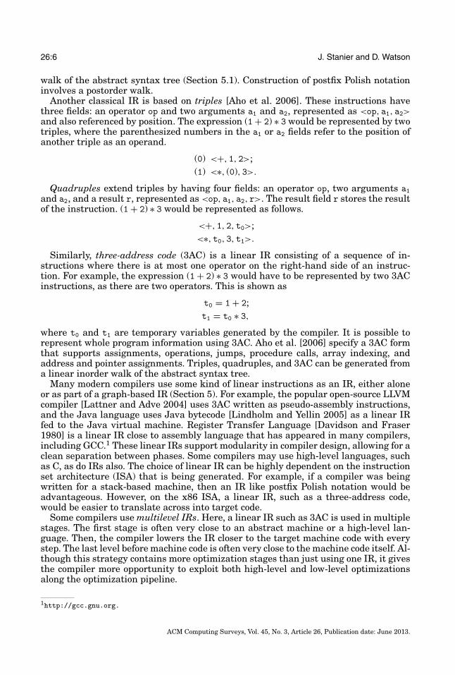
The value state dependence graph [Johnson 2004] builds upon the work of the VDG.In order to solve the termination problem with the VDG, the VSDG adds state de-pendence edges in order to model sequential execution of instructions. A VSDG is alabeled directed graph G = (N, EV , ES, �, N0, N∞) consisting of nodes N with uniqueentry node N0 and exit node N∞, value-dependence edges (drawn solid) EV ∈ N × N,and state-dependence edges (drawn dashed) ES ∈ N × N. The labeling function � as-sociates each node with an operator. Value dependence edges EV perform the samefunction as those in the VDG. State dependence edges ES represent the essential se-quential dependences in the input program. An example of this would be enforcing astore x instruction before a load x instruction, ensuring in no circumstance that thisordering is violated. Like the VDG, the VSDG is explicitly in SSA form. It has twowell-formedness conditions. The first is that � and the EV arity must be consistent.This ensures that a multiplication operator will always have exactly two inputs, andso on. The second is that the VSDG must be acyclic. Nodes in the VSDG representeither operators or constants. Each node has labeled ports in which edges emerge orconnect to.
Like the VDG, conditional branches are represented by γ nodes, except these nowalso return a state as well as data values. Loops are represented differently to the VDG.Here, a θ node is used to model loops. A θ node θ (C, I, R, L, X) sets its internal value toinitial value I. Then, while condition value C holds true, it sets L to the current internalvalue and updates the internal value with the repeat value R. When C evaluates tofalse, computation ceases and the internal value is returned through the X port. Bydefault, this node type is cyclic. Therefore, this does not match against one of the VSDGwell-formedness conditions. As a result, during compilation, all θ nodes are replacedwith two nodes θhead and θ tail, which enclose the loop body. This transformation isdefined as a VSDG G being translated into VSDG Gnoloop form. Given a VSDG G, Gnoloop
is defined to be identical to G except that each θ node θi is replaced with two nodes,θhead
i and θ taili ; edges to or from ports I and L of θi are redirected to θhead
i ; and thoseto or from ports R, X, and C are redirected to θ tail
i . We have shown the VSDG for ourexample code with a loop in Figure 13.
Johnson [2004] constructs the VSDG directly from the AST. However, this is limitedto programs with reducible control flow: the occurrence of goto and switch statementscauses this construction method to halt. Stanier [2011] constructs the VSDG afterperforming an interval analysis technique called structural analysis [Sharir 1980],which allows irreducible control flow to be transformed into reducible control flow.Producing linear code from the VSDG has been explored in a number of ways. Johnsonadds serializing edges to the graph in order to enforce an order of execution, and insertssplit and merge nodes to enable γ nodes to be directly interpreted. However, optimalplacement of split nodes was found to be NP-complete [Upton 2003]. Lawrence [2007]presents a framework that involves translating the VSDG into a PDG by encodinga lazy evaluation strategy, similar to functional programming. This restores enoughcontrol flow information to continue with code generation.
In addition to being an efficient IR for many traditional optimizations [Johnson2004], two traditionally antagonistic passes—register allocation and code motion—canbe performed at the same time using the VSDG [Johnson and Mycroft 2003]. Also,algorithms for utilizing multiple memory access instructions [Seal 2000] for smaller
ACM Computing Surveys, Vol. 45, No. 3, Article 26, Publication date: June 2013.
26:18 J. Stanier and D. Watson
apublic : main()
STATEb
+
1
<
100
+
1
return
R L
I<a>I<STATE>
RLLR
C R<a>R<STATE>
X<STATE> X<a>
head
tail
C
-
1
R
L
TF
L<a>
Fig. 13. The VSDG representation of Figure 8.
code size have been developed [Johnson and Mycroft 2004]. A similar representationto the VSDG called the gated data dependence graph [Upton 2006] has been described,which again uses γ nodes for conditional choice and the concept of state, but uses a μand η loop representation similar to GSA. Firm2 is a data dependence representationalso using the concept of state, but the CFG is retained: the graph is built within theCFG basic blocks. More recently, Tate et al. [2009, 2010] used a similar graph, called theprogram evaluation graph (PEG), in order to optimize by performing equality analysisand translation validation. This work performs optimizations in different sequencesin order to produce multiple versions of the same program, and then picks the bestversion according to heuristics. PEGs have also been used for translation validationseparately [Stepp et al. 2011; Tristan et al. 2011.
5.11. Click’s IR
Click’s IR [Click and Paleczny 1995; Click 1995] is a variation of the PDG based on Petrinets [Petri 1962]. The Petri net model of execution involves control tokens being passedfrom node to node. Similar to the PDG, the set of edges contains two subgraphs: thecontrol dependence subgraph and the data dependence subgraph. Nodes in the graphrepresent operations. REGION nodes perform the same function as those in the PDG.PHI nodes model SSA pseudo-assignment, and IF nodes model conditional branching.Loops are implemented with a REGION node at the head, and an IF node at the end ofthe loop body. A back edge links the TRUE projection from the IF node to the REGION nodeat the loop head. Construction and destruction of this IR are not discussed in detail. A
2http://www.libfirm.org.
ACM Computing Surveys, Vol. 45, No. 3, Article 26, Publication date: June 2013.

Intermediate Representations in Imperative Compilers 26:19
Table II. Number of Citations on Google Scholar for the Paper OriginallyDescribing the IR
IR Paper CitationsPDG Ferrante et al. [1987] 1,659SSA Cytron et al. [1991] 1,576Superblocks Hwu et al. [1993] 546DFG Dennis [1980] 507CFG Allen [1970] 262PDW Ottenstein et al. [1990] 202SSA graph Wolfe [1992] 140VDG Weise et al. [1994] 107Dependence Flow Graph Johnson and Pingali [1993] 107Click’s IR Click and Paleczny [1995] 22VSDG (and similar) Johnson and Mycroft [2003] 21
Note: Accessed January 2011 and ordered by total number.
modified version of this IR is used in the Java HotSpot server compiler [Paleczny et al.2001].
5.12. Dependence Flow Graph
The dependence flow graph [Pingali et al. 1990] is an IR designed to be executableand for dependences to be quickly traversed. Similar to the other data dependence IRs,nodes in the graph represent operations, and edges point from producers to consumers.Value-carrying tokens are passed along edges in the graph in a similar manner tothe Petri net model of execution. An imperative updatable global store is used toenforce an order on operations, and load and store operators interact with this store.Operations that are store-dependent are said to have imperative dependence. Loopsare represented explicitly with loop and until nodes.
Construction of the dependence flow graph [Johnson and Pingali 1993] proceeds byperforming SESE analysis on the CFG. Then, the variables used in each region arediscovered. Then, data dependence edges are inserted in parallel with the CFG controldependence edges to form a base-level graph. A forward flow algorithm then traversesthe graph and maintains the most recent source for each variable; when a region isbypassed, dependences are cut. Then, any dead edges from this cutting process arecleaned up. The authors do not discuss the time complexity of this process.
The dependence flow graph was implemented in the Pidgin compiler.3 The graph isabstractly interpreted according to its operational semantics in order to produce code.A constant propagation algorithm is shown to be simpler to implement but just aseffective as existing IRs.
6. CLASSIFICATION AND USAGE
6.1. Classification and Citations
We now apply the taxonomy of Figure 3 to the IRs, resulting in Table I (see Section 3).We used Google Scholar to find the number of citations for the original paper describingeach IR in Table II. We did this to get an idea of the academic importance of eachrepresentation. We also present a timeline in Figure 14 which plots the publicationyears of the original papers shown in Table II. Note that data here cannot be regardedas being precise. For example, although the seminal SSA publication is the 1991 journalarticle, the idea was in development for a long time at IBM beforehand [Zadeck 2009].
3http://iss.ices.utexas.edu/p.php.
ACM Computing Surveys, Vol. 45, No. 3, Article 26, Publication date: June 2013.

26:20 J. Stanier and D. Watson
1965
1970
1975
1980
1985
1990
1995
2000
2005
PDG
1987
Cla
ssic
al IR
s19
60
Polis
h no
tatio
n, tr
iple
s, qu
adru
ples
, 3A
C.
SSA
gra
ph19
92
GSA
1990
VD
G19
94 Clic
k's I
R19
95SS
A19
91C
FG19
70
Supe
rblo
cks
1993
Pega
sus
2002
PDW
1990
DFG
1980
Dep
ende
nce
Flow
Gra
ph19
93
VSD
G20
04
Fig
.14.
Tim
elin
eof
IRs
base
don
the
publ
icat
ion
date
ofth
eor
igin
alpa
per
desc
ribi
ng
it.T
he
star
tin
gda
teof
clas
sica
lIR
sh
asbe
enes
tim
ated
asn
opr
ecis
ein
form
atio
nis
avai
labl
e.
ACM Computing Surveys, Vol. 45, No. 3, Article 26, Publication date: June 2013.

Intermediate Representations in Imperative Compilers 26:21
Table II shows that, in academia, the PDG and SSA have been very influential.For such fundamental concepts, the CFG and DFG have a relatively low number ofcitations in comparison. However, the CFG and DFG are such commonplace IRs thatauthors often cite compiler textbooks rather than the original papers when referringto them. More recent (post-1990) IRs have a relatively low number of citations.
The timeline in Figure 14 shows that from the development of classical IRs throughto the PDG, there were few radical new developments. IR literature in the 1970’s wasdominated by the CFG and the discovery of new analysis and transformations for it.Likewise, the DFG had a similar effect from 1980 onwards. There is a clear clusteringof new IR publications from 1987–1995. We can only speculate the exact reason forthe increase in new IR developments at that time; however much compiler literature,especially that at the more prestigious compiler conferences, was focusing on vector-ization and parallel computing during this period. This was possibly a result of theinstallation of high-performance machines by Cray and other technology companies.The supercomputer era was short-lived, with most specialist supercomputer manufac-turers apart from Cray filing for bankruptcy by the mid 1990’s. This spike in data flowIRs (and the ILP-specific superblocks) could have been a result of academia trying todevelop compilers that could utilize the parallelism of these machines. As noted byBell [2002], this approach to building massively-parallel special-purpose computers inorder to tackle parallel computing wasn’t a solution to the problem. It did, however,generate a great deal of academic interest, and most importantly, research money. Aca-demic interest in IRs seems to have lessened over the last ten years, but Pegasus andVSDG-like IRs show that they are still a useful tool for specific compilation purposes.
6.2. IR Technology in Current Compilers
We selected a range of widely used compilers and recorded the different IRs beingconstructed during compilation. The compilers we chose are as follows.
—javac. This is the principal Java compiler. It compiles Java source code into bytecode,which is then later executed on the Java virtual machine (VM).
—Java HotSpot server VM. This is the principal server Java compiler. It optimizesand executes Java bytecode, applying many more aggressive optimizations than theHotSpot client VM.
—Jikes RVM [Alpern et al. 2005]. This is a mature open-source VM for Java, developedfrom the IBM Jalapeno project. Jikes RVM is a popular choice for implementing Javaresearch projects.
—GCC. This is the GNU Compiler Collection, which is utilized as the standard compileron a majority of Unix-based operating systems. It has front-ends for a wide varietyof programming languages and targets a large number of processor architectures.
—lcc [Fraser 1991; Fraser and Hanson 1995]. This a simple C compiler written in orderto document the process of compiler design and is highly cited.
—tcc [Poletto et al. 1999]. This is a very compact C compiler often used on embeddeddevices.
—LLVM. This is an open-source compilation framework which is also very popular forresearch projects.
—Mono [Dumbill and Bornstein 2004]. This is an open-source compiler for C#. It alsoshares the same IR as the .NET Framework: Microsoft’s Common IntermediateLanguage.
—Open64 [Chan et al. 2008]. This is an open-source compiler for the Itanium, x86,CUDA, and MIPS architectures.
These compilers were chosen because access is available to their internal structure,and apart from lcc, they are still under frequent development. We show the IRs built
ACM Computing Surveys, Vol. 45, No. 3, Article 26, Publication date: June 2013.

26:22 J. Stanier and D. Watson
Table III. IR Technology Used in Current Compilers
Multi- Stack- GSA/ VDG/DAG CFG DFG SSA Tree level PDG Linear based PDW VSDG-like
javacJikes RVM 3
HotSpot server VM 2GCClcctcc
Clang/LLVMMono 2
Open64 5
by these compilers, in Table III. Other popular proprietary compilers, such as thoseprovided by Intel, do not publish information about their compilation techniques insufficient detail to be considered for this survey. In addition to the IRs mentionedearlier in the survey, we record the presence of a multilevel IR system and the numberof levels. This is an explicit compiler design choice involving multiple levels of IR, fromhigh to low. Jikes RVM features three levels of IR: high-level (HIR), low-level (LIR), andmachine-specific (MIR). HotSpot and mono feature two levels: HIR and LIR. WHIRL,the IR used in open64, uses five levels of IR: very high (VH), high (H), mid (M), low (L),and very low (VL). Using different levels allows optimizations to be written to work onthe level of IR that is most suitable for them.
Aside from lcc and tcc, which can be considered special-purpose compilers (i.e., forsystems with storage and memory concerns), it can be seen that modern compilersshare a common set of IRs.
—A syntax tree in the front-end.—A linear representation, either for transforming or for outputting the program in a
human-readable format.—SSA for performing data flow optimizations.—A CFG for control flow optimizations.
Syntax trees and linear representations can be regarded as foundational compilertechnology. However, the CFG and SSA representations emerged from industry andacademic research, respectively, and have now become standard in mainstream com-pilers. SSA has generated both academic and real-world interest: it is the second mostcited IR in Table II. Interestingly, the most cited IR, the PDG, is only present in theJava HotSpot server compiler, which uses an SSA variation of it. Through informaldiscussion with other compiler researchers, we have yet to note any compiler primarilyusing the PDG, despite it being the most cited. SSA has a number of benefits overthe PDG. First, the time and space complexity of SSA-based algorithms is better. Also,renaming variables with subscripts is intuitively more understandable than the PDG’snumerous different node and edge types. The PDG typically uses more space in mem-ory compared to SSA, and updating and changing the representation is cheaper withSSA, compared to having to rewrite and revalidate the PDG graph.
Understanding is also an important reason that more complicated IRs, regardless oftheir numerous benefits, see less usage than simpler ones. IRs such as the PDG, VDG,and VSDG have been shown to be excellent for optimization; however, they are hard tounderstand intuitively. In a setting such as industry, various constraints, such as timeand manpower, may result in a simpler, more well-understood IR being chosen. Doingso may reduce the time needed to implement it and debug it. Additionally, these IRs do
ACM Computing Surveys, Vol. 45, No. 3, Article 26, Publication date: June 2013.

Intermediate Representations in Imperative Compilers 26:23
not cover destruction in detail, as academic papers are more focused towards showingresults, especially in the constrained space of conference proceedings. Destructing theseIRs for real target architectures can become very complicated. The cost-to-benefit ratiomay be not be advantageous until more detailed literature is available.
An additional reason for the low PDG usage could be similar to the spike in the time-line in Figure 14: the PDG was a seminal IR in the supercomputing era. It produced ahigh number of citations and interest and was most certainly influential in the devel-opment of other IRs; however, most mainstream computer users are only just gettingaffordable access to multicore processors for their home and office machines. Similarly,VDG and VSDG graphs have appeared in a number of influential conferences, yet thetechnology still remains unused outside of academia. In the short term future, theseIRs may well be revisited in attempt to solve the multicore parallelization problemswe are increasingly facing in both academic and mainstream compilation. The time forusing the PDG, VDG-like representations may be now.
6.3. Choosing an IR
The choice of IR in a compiler depends on the goals of the project. The well-trodden routeof syntax trees, CFGs, SSA, and a linear representation benefits from plenty of existingimplementations to investigate, coupled with a comprehensive covering of techniquesin the literature. However, better results, depending on the input language and thetarget architecture, may be achieved by using different IRs. Next, we summarize someof the factors that should be taken into consideration when choosing an IR.
Analysis and Transformation. One main reason for using a particular IR is therelative ease of optimizing the program in that form. If the compiler needs to performa lot of data flow analysis, then it makes sense to opt for a data flow IR, such as SSA. Ifcontrol flow optimization is the primary goal, then CFG is a wise choice. A particularIR typically makes a set of optimizations easier to perform, but will also make anotherset more difficult.
Restriction. How constrained is the program in a particular IR? For example, theCFG is overly constrained: two statements may be in a particular order even thoughthere is nothing that requires them to be ordered in that way. This can have an effecton the effectiveness of optimization. There are more powerful IRs, such as the PDGand VSDG, that allow the program to be expressed in a less constrained way and givethe optimizer more flexibility to perform transformations.
Source and Target Languages. Source languages, such as Haskell and Java, are verydifferent and will commonly be represented by different IRs. Typically, most imperativelanguages map neatly to CFGs, and functional languages map more easily to VSDG-like IRs. Also, the ease of generating the target language is important. A programrepresented as a CFG is straightforward to generate code from; however, more flexibleIRs require additional analysis and transformation to give an ordering on instructionsbefore being passed to the code generator. The target architecture may be a stackmachine, such as the Java VM, or register machine, such as the x86 family.
Construction and Destruction. An IR must be constructed, used, and then destructedbefore generating code. Generally speaking, the more powerful the IR, the greater thedifficulty of construction and destruction, because the further it is removed from thesyntactic structure of the source program.
Time. The more powerful an IR, the greater the amount of time it takes to un-derstand, implement, and debug it. This has obvious connotations for the size of the
ACM Computing Surveys, Vol. 45, No. 3, Article 26, Publication date: June 2013.

26:24 J. Stanier and D. Watson
team required to complete a compiler project, especially if it is going to be used in amainstream compiler.
There is a difficult trade-off between IR power, ease of use, construction, destruction,and human understanding. This trade-off is unique to every compiler project. FromSection 6.2, we can see that mainstream compilers are slowly including more IR ideasfrom research, especially amongst newer open-source projects, such as LLVM, whereresearch projects are feeding into the compiler internals.
7. CONCLUSION
In this article, we have surveyed and summarized the most popular literature oncompiler IRs, and we have categorized them into a taxonomy. In addition, we have at-tempted to gauge the academic importance of particular IRs compared to their impacton the real world. Some IRs, such as SSA, are important in both academia and in main-stream compiler technology. However, some highly cited ideas, such as the PDG, areonly used sparingly out in the wild. As is expected, there is considerable effort involvedin making an experimental IR a reality in large complicated projects, such as GCC.Real compilers have little margin for unexpected bugs or behavior. Newer projects,such as LLVM, which are built with developers and open-source contributors in mind,may allow for more chances for experimental projects to be picked up for mainstreamdevelopment. With the many challenges we are about to face in the heterogeneous mul-ticore processing era, this experimentation is crucial to creating innovative compilertechnology that can keep up with the curve.
ACKNOWLEDGMENTS
We would like to thank the reviewers for their time and valuable suggestions.
REFERENCES
AHO, A. V., LAM, M. S., SETHI, R., AND ULLMAN, J. D. 2006. Compilers: Principles, Techniques, and Tools 2ndEd. Addison-Wesley Longman Publishing Co., Inc., Boston, MA.
ALLEN, F. E. 1970. Control flow analysis. SIGPLAN Not. 5, 7, 1–19.ALLEN, J. R., KENNEDY, K., PORTERFIELD, C., AND WARREN, J. 1983. Conversion of control dependence to data de-
pendence. In Proceedings of the 10th ACM SIGACT-SIGPLAN Symposium on Principles of ProgrammingLanguages (POPL’83). ACM, New York, NY, 177–189.
ALPERN, B., AUGART, S., BLACKBURN, S. M., BUTRICO, M., COCCHI, A., CHENG, P., DOLBY, J., FINK, S., GROVE, D.,HIND, M., MCKINLEY, K. S., MERGEN, M., MOSS, J. E. B., NGO, T., AND SARKAR, V. 2005. The jikes researchvirtual machine project: Building an open-source research community. IBM Syst. J. 44, 399–417.
BALL, T. AND HORWITZ, S. 1992. Constructing control flow from control dependence. Tech. rep. CS-TR-1992-1091, University of Wisconsin-Madison.
BALLANCE, R. A., MACCABE, A. B., AND OTTENSTEIN, K. J. 1990. The program dependence Web: A representationsupporting control-, data-, and demand-driven interpretation of imperative languages. In Proceedingsof the ACM SIGPLAN Conference on Programming Language Design and Implementation (PLDI’90).257–271.
BARTON, R. S. 1961. A new approach to the functional design of a digital computer. In Proceedings of theWestern Joint IRE-AIEE-ACM Computer Conference (Western’61). ACM, New York, NY, 393–396.
BATES, S. AND HORWITZ, S. 1993. Incremental program testing using program dependence graphs. In Pro-ceedings of the 20th ACM SIGPLAN-SIGACT Symposium on Principles of Programming Languages(POPL’93). ACM, New York, NY, 384–396.
BAXTER, W. AND BAUER, III, H. R. 1989. The program dependence graph and vectorization. In Proceedingsof the 16th ACM SIGPLAN-SIGACT Symposium on Principles of Programming Languages (POPL’89).ACM, New York, NY, 1–11.
BELL, G. 2002. A brief history of supercomputing: “The Crays”, Clusters and Beowulfs, Centers.What next? http://research.microsoft.com/en-us/um/people/gbell/supers/supercomputing-a_brief_history_1965_2002.htm.
BIGGS, N. 1993. Algebraic Graph Theory 2nd Ed. Cambridge University Press, Cambridge, U.K.
ACM Computing Surveys, Vol. 45, No. 3, Article 26, Publication date: June 2013.

Intermediate Representations in Imperative Compilers 26:25
BILARDI, G. AND PINGALI, K. 2003. Algorithms for computing the static single assignment form. J. ACM 50, 3,375–425.
BOISSINOT, B., DARTE, A., RASTELLO, F., DE DINECHIN, B. D., AND GUILLON, C. 2009. Revisiting out-of-SSA trans-lation for correctness, code quality and efficiency. In Proceedings of the 7th Annual IEEE/ACM Interna-tional Symposium on Code Generation and Optimization (CGO’09). IEEE Computer Society, Washington,DC, 114–125.
BRIGGS, P., COOPER, K. D., HARVEY, T. J., AND SIMPSON, L. T. 1998. Practical improvements to the constructionand destruction of static single assignment form. Softw. Pract. Exper. 28, 8, 859–881.
BRIGGS, P., COOPER, K. D., AND TORCZON, L. 1992. Rematerialization. In Proceedings of the ACM SIGPLANConference on Programming Language Design and Implementation (PLDI’92). ACM, New York, NY,311–321.
BUDIU, M. AND GOLDSTEIN, S. C. 2002. Pegasus: An efficient intermediate representation. Tech. rep. CMU-CS-02-107, Carnegie Mellon University, Pittsburgh, PA. May.
BYERS, D., KAMKAR, M., AND PALSSON, T. 2001. Syntax-directed construction of value dependence graphs. InProceedings of the IEEE International Conference on Software Maintenance (ICSM’01). IEEE ComputerSociety, Washington, DC, 692–703.
CAMPBELL, P., KRISHNA, K., AND BALLANCE, R. A. 1993. Refining and defining the program dependence web.Tech. rep., University of New Mexico, Albuquerque, NM.
CHAN, S., GAO, G., CHAPMAN, B., LINTHICUM, T., AND DASGUPTA, A. 2008. Open64 compiler infrastructure foremerging multicore/manycore architecture. In Proceedings of the IEEE International Symposium onParallel and Distributed Processing (IPDPS’08). 1.
CHOW, F. C. AND GANAPATHI, M. 1983. Intermediate program representations in compiler construction—abibliography. SIGPLAN Not. 18, 21–23.
CLICK, C. 1995. Global code motion/global value numbering. In Proceedings of the ACM SIGPLAN Conferenceon Programming Language Design and Implemantation (PLDI’95). ACM, New York, NY, 246–257.
CLICK, C. AND PALECZNY, M. 1995. A simple graph-based intermediate representation. In Proceedings of theACM SIGPLAN Workshop on Intermediate Representations (IR’95). ACM, New York, NY, 35–49.
CONWAY, M. E. 1958. A proposal for an UNCOL. Commun. ACM 1, 10 (Oct.), 5–8.COOPER, K. D., SIMPSON, L. T., AND VICK, C. A. 2001. Operator strength reduction. ACM Trans. Program. Lang.
Syst. 23, 5, 603–625.CYTRON, R., FERRANTE, J., ROSEN, B. K., WEGMAN, M. N., AND ZADECK, F. K. 1991. Efficiently computing static
single assignment form and the control dependence graph. ACM Trans. Program. Lang. Syst. 13, 4 (Oct),451–490.
DAVIDSON, J. W. AND FRASER, C. W. 1980. The design and application of a retargetable peephole optimizer. ACMTrans. Program. Lang. Syst. 2, 191–202.
DENNIS, J. B. 1974. First version of a data flow procedure language. In Proceedings Colloque sur la Program-mation on Programming Symposium. Lecture Notes in Computer Science, vol. 19, Springer-Verlag,London, U.K., 362–376.
DENNIS, J. B. 1980. Data flow supercomputers. Computer 13, 11, 48–56.DUMBILL, E. AND BORNSTEIN, N. M. 2004. Mono (Developer’s Notebook). O’Reilly Media, Inc., Sebastopol, CA.EBNER, D., BRANDNER, F., SCHOLZ, B., KRALL, A., WIEDERMANN, P., AND KADLEC, A. 2008. Generalized instruction
selection using SSA-graphs. In Proceedings of the ACM SIGPLAN-SIGBED Conference on Languages,Compilers, and Tools for Embedded Systems (LCTES’08). ACM, New York, NY, 31–40.
EUKASIEWICZ, J. 1957. Aristotle’s Syllogistic From the Standpoint of Modern Formal Logic 2nd Ed. OxfordClarendon Press, Oxford, U.K.
FERRANTE, J. AND MACE, M. 1985. On linearizing parallel code. In Proceedings of the 12th ACM SIGACT-SIGPLAN Symposium on Principles of Programming Languages (POPL’85). ACM, New York, NY, 179–190.
FERRANTE, J., MACE, M., AND SIMONS, B. 1988. Generating sequential code from parallel code. In Proceedingsof the 2nd International Conference on Supercomputing (ICS’88). ACM, New York, NY, 582–592.
FERRANTE, J., OTTENSTEIN, K. J., AND WARREN, J. D. 1987. The program dependence graph and its use inoptimization. ACM Trans. Program. Lang. Syst. 9, 3, 319–349.
FRASER, C. W. 1991. A retargetable compiler for ANSI C. SIGPLAN Not. 26, 10, 29–43.FRASER, C. W. AND HANSON, D. R. 1995. A Retargetable C Compiler: Design and Implementation. Addison-
Wesley Longman Publishing Co., Inc., Boston, MA.HARROLD, M. J., MALLOY, B., AND ROTHERMEL, G. 1993. Efficient construction of program dependence graphs.
In Proceedings of the ACM SIGSOFT International Symposium on Software Testing and Analysis(ISSTA’93). ACM, New York, NY, 160–170.
ACM Computing Surveys, Vol. 45, No. 3, Article 26, Publication date: June 2013.

26:26 J. Stanier and D. Watson
HAVLAK, P. 1994. Construction of thinned gated single-assignment form. In Proceedings of the 6th Inter-national Workshop on Languages and Compilers for Parallel Computing (LCPC’94). Lecture Notes inComputer Science, vol. 768, Springer-Verlag, London, U.K, 477–499.
HECHT, M. S. AND ULLMAN, J. D. 1972. Flow graph reducibility. In Proceedings of the 4th ACM Symposium onTheory of Computing (STOC’72). ACM, New York, NY, 238–250.
HWU, W.-M. W., MAHLKE, S. A., CHEN, W. Y., CHANG, P. P., WARTER, N. J., BRINGMANN, R. A., OUELLETTE, R. G.,HANK, R. E., KIYOHARA, T., HAAB, G. E., HOLM, J. G., AND LAVERY, D. M. 1993. The superblock: An effectivetechnique for VLIW and superscalar compilation. J. Supercomput. 7, 1–2, 229–248.
JOHNSON, N. AND MYCROFT, A. 2003. Combined code motion and register allocation using the value statedependence graph. In Proceedings of the 12th International Conference on Compiler Construction (CC’03).Lecture Notes in Computer Science, vol. 2622, Springer-Verlag, Berlin, Heidelberg, 1–16.
JOHNSON, N. AND MYCROFT, A. 2004. Using multiple memory access instructions for reducing code size. InProceedings of the 13th International Conference on Compiler Construction (CC’04). Lecture Notes inComputer Science, vol. 2985, Springer-Verlag, Berlin, Heidelberg, 265–280.
JOHNSON, N. E. 2004. Code size optimization for embedded processors. Tech. rep. UCAM-CL-TR-607, Univer-sity of Cambridge, Computer Laboratory. Nov.
JOHNSON, R. AND PINGALI, K. 1993. Dependence-based program analysis. In Proceedings of the ACM SIGPLANConference on Programming Language Design and Implementation (PLDI’93). ACM, New York, NY,78–89.
LATTNER, C. AND ADVE, V. 2004. LLVM: A compilation framework for lifelong program analysis & transforma-tion. In Proceedings of the International Symposium on Code Generation and Optimization (CGO’04).IEEE Computer Society, Washington, DC, 75.
LAWRENCE, A. C. 2007. Optimizing compilation with the value state dependence graph. Tech. rep. UCAM-CL-TR-705, University of Cambridge, Computer Laboratory. Dec.
LINDHOLM, T. AND YELLIN, F. 2005. The Java Virtual Machine specification. http://java.sun.com/docs/books/jvms/second_edition/html/VMSpecTOC.doc.html.
MAHLKE, S. A., LIN, D. C., CHEN, W. Y., HANK, R. E., AND BRINGMANN, R. A. 1995. Effective compiler support forpredicated execution using the hyperblock. IEEE Computer Society Press, Los Alamitos, CA, 161–170.
MUCHNICK, S. S. 1997. Advanced Compiler Design and Implemantation. Morgan Kaufmann Publishers Inc.,San Francisco, CA.
OTTENSTEIN, K. J. 1984. Intermediate program representations in compiler construction: A supplementalbibliography. SIGPLAN Not. 19, 25–27.
OTTENSTEIN, K. J., BALLANCE, R. A., AND MACCABE, A. B. 1990. The program dependence Web: A representationsupporting control-, data-, and demand-driven interpretation of imperative languages. In Proceedingsof the ACM SIGPLAN Conference on Programming Language Design and Implementation (PLDI’90).ACM, New York, NY, 257–271.
OTTENSTEIN, K. J. AND OTTENSTEIN, L. M. 1984. The program dependence graph in a software developmentenvironment. In Proceedings of the 1st ACM SIGSOFT/SIGPLAN Software Engineering Symposium onPractical Software Development Environments (SDE’84). ACM, New York, NY, 177–184.
PALECZNY, M., VICK, C., AND CLICK, C. 2001. The Java HotSpotTM server compiler. In Proceedings of the JavaTM
Virtual Machine Research and Technology Symposium (JVM’01). USENIX Association, Berkeley, CA,1–12.
PETRI, C. A. 1962. Kommunikation mit Automaten, Ph.D. dissertation. Tech. rep., University of Bonn, Bonn,Germany.
PINGALI, K., BECK, M., JOHNSON, R. C., MOUDGILL, M., AND STODGHILL, P. 1990. Dependence flow graphs: Analgebraic approach to program dependencies. Tech. rep., Cornell University, Ithaca, NY.
POLETTO, M., HSIEH, W. C., ENGLER, D. R., AND KAASHOEK, M. F. 1999. C and tcc: A language and compiler fordynamic code generation. ACM Trans. Program. Lang. Syst. 21, 324–369.
ROSEN, B. K., WEGMAN, M. N., AND ZADECK, F. K. 1988. Global value numbers and redundant computations. InProceedings of the 15th ACM SIGPLAN-SIGACT Symposium on Principles of Programming Languages(POPL’88). 12–27.
SARKAR, V. 1991. Automatic partitioning of a program dependence graph into parallel tasks. IBM J. Res.Dev. 35, 779–804.
SCHAFER, S. AND SCHOLZ, B. 2007. Optimal chain rule placement for instruction selection based on SSAgraphs. In Proceedings of the 10th International Workshop on Software & Compilers for EmbeddedSystems (SCOPES’07). ACM, New York, NY, 91–100.
SEAL, D. 2000. ARM Architecture Reference Manual 2nd Ed. Addison-Wesley Longman Publishing Co., Inc.,Boston, MA.
ACM Computing Surveys, Vol. 45, No. 3, Article 26, Publication date: June 2013.

Intermediate Representations in Imperative Compilers 26:27
SHARIR, M. 1980. Structural analysis: A new approach to flow analysis in optimizing compilers. Comput.Lang. 5, 3–4, 141–153.
SIMONS, B., ALPERN, D., AND FERRANTE, J. 1990. A foundation for sequentializing parallel code. In Proceedingsof the 2nd Annual ACM Symposium on Parallel Algorithms and Architectures (SPAA’90). ACM, NewYork, NY, 350–359.
SREEDHAR, V. C., JU, R. D.-C., GILLIES, D. M., AND SANTHANAM, V. 1999. Translating out of static single as-signment form. In Proceedings of the 6th International Symposium on Static Analysis (SAS’99). LectureNotes in Computer Science, vol. 1694, Springer-Verlag, Berlin, Heidelberg, 194–210.
STANIER, J. 2011. Removing and restoring control flow with the value state dependence graph. Tech. rep.,University of Sussex, Eost Sussex, U.K., School of Informatics. Oct.
STAUFFER, J. D. 1978. LCL: A compiler and language for logical mask checking. Tech. rep., Albuquerque, NM.STEENSGAARD, B. 1993. Sequentializing program dependence graphs for irreducible programs. Tech. rep.
MSR-TR-93-14, Microsoft Research, Redmond, WA.STEPP, M., TATE, R., AND LERNER, S. 2011. Equality-based translation validator for livm. In Proceedings of the
23rd International Conference on Computer Aided Verification (CAV), G. Gopalakrishnan and S. Qadeer,Eds., Lecture Notes in Computer Science, vol. 6806. Springer, Berlin, Heidelberg, 737–742.
STOLTZ, E., GERLEK, M. P., AND WOLFE, M. 1993. Extended SSA with factored use-def chains to supportoptimization and parallelism. In Proceedings of the 27th Annual Hawaii International Conference onSystem Sciences. 43–52.
TATE, R., STEPP, M., AND LERNER, S. 2010. Generating compiler optimization from proofs. In Proceedings of the37th Annual ACM SIGPLAN-SIGACT Symposium on Principles of Programming Languages (POPL’10).ACM, New York, NY, 389–402.
TATE, R., STEPP, M., TATLOCK, Z., AND LERNER, S. 2009. Equality saturation: A new approach to optimization.In Proceedings of the 36th Annual ACM SIGPLAN-SIGACT Symposium on Principles of ProgrammingLanguages (POPL’09). ACM, New York, NY, 264–276.
TATE, R., STEPP, M., TATLOCK, Z., AND LERNER, S. 2011. Equality satuaration: A new approach to optimazation.Logical Methods Comput. Sci. 7, 1.
TORCZON, L. AND COOPER, K. 2007. Engineering A Compiler. Morgan Kaufmann Publishers Inc., San Francisco,CA.
TREMBLAY, J.-P. AND SORENSON, P. G. 1985. Theory and Practice of Compiler Writing. McGraw-Hill, Inc., NewYork, NY.
TRISTAN, J.-B., GOVEREAU, P., AND MORRISETT, G. 2011. Evaluating value-graph translation validation for LLVM.In Proceedings of the 32nd ACM SIGPLAN Conference on Programming Language Design and Imple-mentation (PLDI’11). ACM, New York, NY, 295–305.
TU, P. AND PADUA, D. 1995. Efficient building and placing of gating functions. In Proceedings of the ACMSIGPLAN Conference on Programming Language Design and Implementation (PLDI’95). ACM, NewYork, NY, 47–55.
UPTON, E. 2003. Optimal sequentialization of gated data dependence graphs is NP-Complete. In Proceedingsof the International Conference on Parallel and Distributed Processing Techniques and Applications(PDPTA’03), H. R. Arabnia and Y. Mun, Eds., CSREA Press, 1767–1770.
UPTON, E. 2006. Compiling with data dependence graphs. Tech. rep., University of Cambridge, Cambridge,U.K., Computer Laboratory. July.
WEGMAN, M. N. AND ZADECK, F. K. 1991. Constant propagation with conditional branches. ACM Trans. Pro-gram. Lang. Syst. 13, 2 (Apr), 181–210.
WEISE, D., CREW, R. F., ERNST, M., AND STEENSGAARD, B. 1994. Value dependence graphs: Representation withouttaxation. In Proceedings of the 21st Annual ACM Symposium on Principles of Programming Languages(POPL’94). 297–310.
WOLFE, M. 1992. Beyond induction variables. In Proceedings of the ACM SIGPLAN Conference on Program-ming Language Design and Implementation (PLDI’92). ACM, New York, NY, 162–174.
ZADECK, F. K. 2009. The development of static single assignment form. Presented at the Static Single-Assignment Form Seminar (SSA’09).
Received May 2011; revised September 2011; accepted October 2011
ACM Computing Surveys, Vol. 45, No. 3, Article 26, Publication date: June 2013.