intermot hydraulic motors ihm series technical … - ihm series - comple… · 150 159 160 200 15...
TRANSCRIPT

The data specified into this catalogue are for product description purpose only and must not be interpreted as warranted characteristic in legal sense. Intermot reserves the right to implement modification without notice.
www.intermot.com DOC 140624.0 [email protected]
1
Intermot Hydraulic Motors
IHM Series
TECHNICAL CATALOGUE
INDEX
MOTOR TECHNICAL DATA Pag. 2
IHM H1 SERIES Pag. 4
IHM H1.5 SERIES Pag. 8
IHM H2 SERIES Pag. 12
IHM H3 SERIES Pag. 16
IHM H4 SERIES Pag. 20
IHM H5 SERIES Pag. 24
IHM H6 SERIES Pag. 28
IHM H7 SERIES Pag. 32
FLOW DISTRIBUTORS Pag. 36

The data specified into this catalogue are for product description purpose only and must not be interpreted as warranted characteristic in legal sense. Intermot reserves the right to implement modification without notice.
www.intermot.com DOC 140624.0 [email protected]
2
Motor Technical Data
MO
DE
L
N°
of
pis
ton
s
Dis
pla
cem
en
t
Pressure Speed Torque
Dry Mass
Max Cont.
Peak Minimum
speed Max
speed Rated Specific
cm3/rev bar rpm Nm Nm/MPa kg
IHM
H1
70
5
77 250 320 15 1500 284 11
20
80 91 250 320 15 1250 335 13
100 96 250 320 15 1000 355 14
125 126 200 250 15 1000 371 19
150 159 160 200 15 1000 376 24
200 196 160 200 15 800 464 29
IHM
H1
.5
100
5
113 250 320 15 1250 419 17
27
125 138 250 320 15 1250 512 20
150 159 250 320 15 1000 588 24
175 180 200 250 15 1000 532 27
200 207 200 250 8 800 611 31
250 235 160 200 8 630 556 35
280 276 160 200 8 500 653 41
IHM
H2
175
5
181 250 320 8 1000 670 27
35
200 201 250 320 8 800 743 30
220 222 250 320 8 800 819 33
250 254 200 250 8 630 752 38
300 289 200 250 8 500 856 43
350 340 200 250 8 400 1000 50
400 380 180 225 8 350 1008 56
IHM
H3
400
5
397 250 320 5 630 1469 59
57,5
450 452 250 320 5 630 1672 67
500 491 200 250 5 500 1451 73
600 594 200 250 4 500 1756 88
700 683 160 200 4 400 1616 101
750 754 160 200 4 320 1785 112

The data specified into this catalogue are for product description purpose only and must not be interpreted as warranted characteristic in legal sense. Intermot reserves the right to implement modification without notice.
www.intermot.com DOC 140624.0 [email protected]
3
MO
DE
L
N°
of
pis
ton
s
Dis
pla
cem
en
t
Pressure Speed Torque
Dry Mass
Max Cont.
Peak Minimum
speed Max
speed Rated Specific
cm3/rev bar rpm Nm Nm/MPa kg
IHM
H4
700
5
707 250 320 4 400 2612 104
94
800 784 250 320 4 400 2899 116
900 894 250 320 4 400 3306 132
1000 981 200 250 3 320 2902 145
1100 1104 200 250 3 320 3265 163
1200 1234 160 200 3 320 2919 182
1300 1301 160 200 3 250 3079 192
IHM
H5
1400
5
1413 250 320 2 400 5224 209
170
1600 1648 200 250 2 400 4874 244
1800 1815 200 250 2 350 5367 268
2000 2035 180 225 2 350 5416 301
2400 2267 160 200 2 250 5364 335
IHM
H6
2500
5
2553 250 320 2 200 9438 378
298
2800 2683 200 250 1 200 7935 397
3000 3063 200 250 1 200 9057 453
3200 3218 200 250 1 160 9518 476
3500 3561 200 250 1 160 10530 527
4000 4153 180 225 1 160 11053 614
4500 4522 160 200 1 160 10698 669
5000 4828 160 200 1 160 11423 714
IHM
H7
5000
7
4968 200 250 1 160 14626 731
550
5400 5452 200 250 1 160 16125 806
6000 5984 200 250 0,5 125 17697 885
6300 6540 180 220 0,5 125 17408 967
7000 7122 160 200 0,5 125 16849 1053

The data specified into this catalogue are for product description purpose only and must not be interpreted as warranted characteristic in legal sense. Intermot reserves the right to implement modification without notice.
www.intermot.com DOC 140624.0 [email protected]
4
Intermot Hydraulic Motors
IHM Series
H1 Models
IHM 70 – 80 – 100 – 125 – 150 – 200 H1
INDEX
TECHNICAL DATA Pag. 5
IHM 70 – 80 – 100 – 125
150 – 200 H1 Pag. 6
ORDERING INSTRUCTIONS Pag. 7

The data specified into this catalogue are for product description purpose only and must not be interpreted as warranted characteristic in legal sense. Intermot reserves the right to implement modification without notice.
www.intermot.com DOC 140624.0 [email protected]
5
IHM H1 Technical data
MO
DE
L
N°
of
pis
ton
s
Dis
pla
ce
me
nt
Pressure Speed Torque
Dry Mass
Max Cont.
Peak Minimum
speed Max
speed Rated Specific
cm3/rev bar rpm Nm Nm/MPa kg
IHM
H1
70
5
77 250 320 15 1500 284 11
20
80 91 250 320 15 1250 335 13
100 96 250 320 15 1000 355 14
125 126 200 250 15 1000 371 19
150 159 160 200 15 1000 376 24
200 196 160 200 15 800 464 29
The data specified into this catalogue are for product description purpose only and must not be interpreted as warranted characteristic in legal sense. Intermot reserves the right to implement modification without notice.
www.intermot.com DOC 140624.0 [email protected]
6
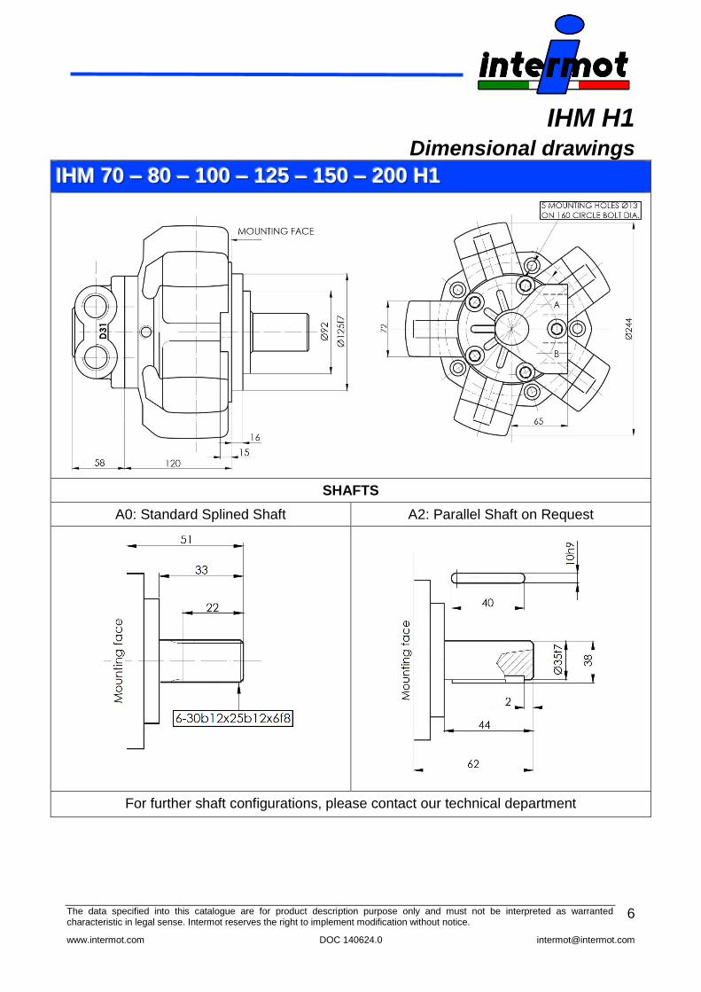
IHM H1 Dimensional drawings
IIIHHHMMM 777000 ––– 888000 ––– 111000000 ––– 111222555 ––– 111555000 ––– 222000000 HHH111
SHAFTS
A0: Standard Splined Shaft A2: Parallel Shaft on Request
For further shaft configurations, please contact our technical department

The data specified into this catalogue are for product description purpose only and must not be interpreted as warranted characteristic in legal sense. Intermot reserves the right to implement modification without notice.
www.intermot.com DOC 140624.0 [email protected]
7
IHM H1
Ordering instructions
IHM _ _ _ H1 A _ D _ _
Model
Displacement
70 cc/rev
80 cc/rev
100 cc/rev
125 cc/rev
150 cc/rev
200 cc/rev
Housing
H1
Shaft
A0 – Standard splined shaft
A2 – Parallel keyed shaft
Distributor
D31 – ¾” BSP
D310 – 1” BSP
D40 – 1” BSP
D47 – SAE 1” 3000 psi flange
EXAMPLE : IHM 100 H1 A0 D31

The data specified into this catalogue are for product description purpose only and must not be interpreted as warranted characteristic in legal sense. Intermot reserves the right to implement modification without notice.
www.intermot.com DOC 140624.0 [email protected]
8
Intermot Hydraulic Motors
IHM Series
H1.5 Models
IHM 100 – 125 – 150 – 175 – 200 – 250 – 280 H1.5
INDEX
TECHNICAL DATA Pag. 9
IHM 100 – 125 – 150 – 175
200 – 250 – 280 H1.5 Pag. 10
ORDERING INSTRUCTIONS Pag. 11

The data specified into this catalogue are for product description purpose only and must not be interpreted as warranted characteristic in legal sense. Intermot reserves the right to implement modification without notice.
www.intermot.com DOC 140624.0 [email protected]
9
IHM H1.5
Technical data
MO
DE
L
N°
of
pis
ton
s
Dis
pla
ce
me
nt
Pressure Speed Torque
Dry Mass
Max Cont.
Peak Minimum
speed Max
speed Rated Specific
cm3/rev bar rpm Nm Nm/MPa kg
IHM
H1.5
100
5
113 250 320 15 1250 419 17
27
125 138 250 320 15 1250 512 20
150 159 250 320 15 1000 588 24
175 180 200 250 15 1000 532 27
200 207 200 250 8 800 611 31
250 235 160 200 8 630 556 35
280 276 160 200 8 500 653 41

The data specified into this catalogue are for product description purpose only and must not be interpreted as warranted characteristic in legal sense. Intermot reserves the right to implement modification without notice.
www.intermot.com DOC 140624.0 [email protected]
10
IHM H1.5
Dimensional drawings
IIIHHHMMM 111000000 ––– 111222555 ––– 111555000 ––– 111777555 ––– 222000000 ––– 222555000 ––– 222888000 HHH111...555
SHAFTS
A0: Standard Splined Shaft A2: Parallel Shaft on Request A3: Internal Splined Shaft
For further shaft configurations, please contact our technical department

The data specified into this catalogue are for product description purpose only and must not be interpreted as warranted characteristic in legal sense. Intermot reserves the right to implement modification without notice.
www.intermot.com DOC 140624.0 [email protected]
11
IHM H1.5
Ordering instructions
IHM _ _ _ H1.5 A _ D _ _
Model
Displacement
100 cc/rev
125 cc/rev
150 cc/rev
175 cc/rev
200 cc/rev
250 cc/rev
280 cc/rev
Housing
H1.5
Shaft
A0 – Standard splined shaft
A2 – Parallel keyed shaft
A3 – Internal Splined shaft
Distributor
D31 – ¾” BSP
D310 – 1” BSP
D40 – 1” BSP
D47 – SAE 1” 3000 psi flange
EXAMPLE : IHM 250 H1.5 A0 D31

The data specified into this catalogue are for product description purpose only and must not be interpreted as warranted characteristic in legal sense. Intermot reserves the right to implement modification without notice.
www.intermot.com DOC 140624.0 [email protected]
12
Intermot Hydraulic Motors
IHM Series
H2 Models
IHM 175 – 200 – 220 – 250 – 300 – 350 – 400 H2
INDEX
TECHNICAL DATA Pag. 13
IHM 175 – 200 – 220 – 250
300 – 350 – 400 H2 Pag. 14
ORDERING INSTRUCTIONS Pag. 15

The data specified into this catalogue are for product description purpose only and must not be interpreted as warranted characteristic in legal sense. Intermot reserves the right to implement modification without notice.
www.intermot.com DOC 140624.0 [email protected]
13
IHM H2
Technical data
MO
DE
L
N°
of
pis
ton
s
Dis
pla
ce
me
nt
Pressure Speed Torque
Dry Mass
Max Cont.
Peak Minimum
speed Max
speed Rated Specific
cm3/rev bar rpm Nm Nm/MPa kg
IHM
H2
175
5
181 250 320 8 1000 670 27
35
200 201 250 320 8 800 743 30
220 222 250 320 8 800 819 33
250 254 200 250 8 630 752 38
300 289 200 250 8 500 856 43
350 340 200 250 8 400 1000 50
400 380 180 225 8 350 1008 56

The data specified into this catalogue are for product description purpose only and must not be interpreted as warranted characteristic in legal sense. Intermot reserves the right to implement modification without notice.
www.intermot.com DOC 140624.0 [email protected]
14
IHM H2
Dimensional drawings
IIIHHHMMM 111777555 ––– 222000000 ––– 222222000 ––– 222555000 ––– 333000000 ––– 333555000 ––– 444000000 HHH222
SHAFTS
A0: Standard Splined Shaft A2: Parallel Shaft on Request A3: Internal Splined Shaft
For further shaft configurations, please contact our technical department

The data specified into this catalogue are for product description purpose only and must not be interpreted as warranted characteristic in legal sense. Intermot reserves the right to implement modification without notice.
www.intermot.com DOC 140624.0 [email protected]
15
IHM H2
Ordering instructions
IHM _ _ _ H2 A _ D _ _
Model
Displacement
175 cc/rev
200 cc/rev
220 cc/rev
220 cc/rev
250 cc/rev
300 cc/rev
350 cc/rev
400 cc/rev
Housing
H2
Shaft
A0 – Standard splined shaft
A2 – Parallel keyed shaft
A3 – Internal splined shaft
Distributor
D31 – ¾” BSP
D310 – 1” BSP
D40 – 1” BSP
D47 – SAE 1” 3000 psi flange
EXAMPLE : IHM 400 H2 A0 D40

The data specified into this catalogue are for product description purpose only and must not be interpreted as warranted characteristic in legal sense. Intermot reserves the right to implement modification without notice.
www.intermot.com DOC 140624.0 [email protected]
16
Intermot Hydraulic Motors
IHM Series
H3 Models
IHM 400 – 450 – 500 – 600 – 700 – 750 H3
INDEX
TECHNICAL DATA Pag. 17
IHM 400 – 450 – 500 – 600
700 – 750 H3 Pag. 18
ORDERING INSTRUCTIONS Pag. 19

The data specified into this catalogue are for product description purpose only and must not be interpreted as warranted characteristic in legal sense. Intermot reserves the right to implement modification without notice.
www.intermot.com DOC 140624.0 [email protected]
17
IHM H3
Technical data
MO
DE
L
N°
of
pis
ton
s
Dis
pla
ce
me
nt
Pressure Speed Torque
Dry Mass
Max Cont.
Peak Minimum
speed Max
speed Rated Specific
cm3/rev bar rpm Nm Nm/MPa kg
IHM
H3
400
5
397 250 320 5 630 1469 59
57,5
450 452 250 320 5 630 1672 67
500 491 200 250 5 500 1451 73
600 594 200 250 4 500 1756 88
700 683 160 200 4 400 1616 101
750 754 160 200 4 320 1785 112

The data specified into this catalogue are for product description purpose only and must not be interpreted as warranted characteristic in legal sense. Intermot reserves the right to implement modification without notice.
www.intermot.com DOC 140624.0 [email protected]
18
IHM H3
Dimensional drawings
IIIHHHMMM 444000000 ––– 444555000 ––– 555000000 ––– 666000000 ––– 777000000 ––– 777555000 HHH333
SHAFTS
A0: Standard splined shaft A1: Splined shaft on request
For further shaft configurations, please contact our technical department

The data specified into this catalogue are for product description purpose only and must not be interpreted as warranted characteristic in legal sense. Intermot reserves the right to implement modification without notice.
www.intermot.com DOC 140624.0 [email protected]
19
IHM H3
Ordering instructions
IHM _ _ _ H3 A _ D _ _
Model
Displacement
400 cc/rev
450 cc/rev
500 cc/rev
600 cc/rev
700cc/rev
750 cc/rev
Housing
H3
Shaft
A0 – Standard splined shaft
A2 – Parallel keyed shaft
Distributor
D31 – ¾” BSP
D310 – 1” BSP
D40 – 1” BSP
D47 – SAE 1” 3000 psi flange
EXAMPLE : IHM 600 H3 A0 D40

The data specified into this catalogue are for product description purpose only and must not be interpreted as warranted characteristic in legal sense. Intermot reserves the right to implement modification without notice.
www.intermot.com DOC 140624.0 [email protected]
20
Intermot Hydraulic Motors
IHM Series
H4 Models
IHM 700 – 800 – 900 – 1000 – 1100 – 1200 – 1300 H4
INDEX
TECHNICAL DATA Pag. 21
IHM 700 – 800 – 900 – 1000
1100 – 1200 – 1300 H4 Pag. 22
ORDERING INSTRUCTIONS Pag. 23

The data specified into this catalogue are for product description purpose only and must not be interpreted as warranted characteristic in legal sense. Intermot reserves the right to implement modification without notice.
www.intermot.com DOC 140624.0 [email protected]
21
IHM H4
Technical data
MO
DE
L
N°
of
pis
ton
s
Dis
pla
ce
me
nt
Pressure Speed Torque
Dry Mass
Max Cont.
Peak Minimum
speed Max
speed Rated Specific
cm3/rev bar rpm Nm Nm/MPa kg
IHM
H4
700
5
707 250 320 4 400 2612 104
94
800 784 250 320 4 400 2899 116
900 894 250 320 4 400 3306 132
1000 981 200 250 3 320 2902 145
1100 1104 200 250 3 320 3265 163
1200 1234 160 200 3 320 2919 182
1300 1301 160 200 3 250 3079 192

The data specified into this catalogue are for product description purpose only and must not be interpreted as warranted characteristic in legal sense. Intermot reserves the right to implement modification without notice.
www.intermot.com DOC 140624.0 [email protected]
22
IHM H4
Dimensional drawings
IIIHHHMMM 777000000 ––– 888000000 ––– 999000000 ––– 111000000000 ––– 111111000000 ––– 111222000000 ––– 111333000000 HHH444
SHAFTS
A0: Standard splined shaft A2: Parallel shaft on request
For further shaft configurations, please contact our technical department

The data specified into this catalogue are for product description purpose only and must not be interpreted as warranted characteristic in legal sense. Intermot reserves the right to implement modification without notice.
www.intermot.com DOC 140624.0 [email protected]
23
IHM H4
Ordering instructions
IHM _ _ _ _ H4 A _ D _ _
Model
Displacement
700 cc/rev
800 cc/rev
900 cc/rev
1000 cc/rev
1100 cc/rev
1200 cc/rev
1300 cc/rev
Housing
H4
Shaft
A0 – Standard splined shaft
A2 – Parallel keyed shaft
Distributor
D31 – ¾” BSP
D310 – 1” BSP
D40 – 1” BSP
D47 – SAE 1” 3000 psi flange
EXAMPLE : IHM 1000 H4 A0 D40

The data specified into this catalogue are for product description purpose only and must not be interpreted as warranted characteristic in legal sense. Intermot reserves the right to implement modification without notice.
www.intermot.com DOC 140624.0 [email protected]
24
Intermot Hydraulic Motors
IHM Series
H5 Models
IHM 1400 – 1600 – 1800 – 2000 – 2400 H5
INDEX
TECHNICAL DATA Pag. 25
IHM 1400 – 1600 – 1800
2000 – 2400 H5 Pag. 26
ORDERING INSTRUCTIONS Pag. 27

The data specified into this catalogue are for product description purpose only and must not be interpreted as warranted characteristic in legal sense. Intermot reserves the right to implement modification without notice.
www.intermot.com DOC 140624.0 [email protected]
25
IHM H5
Technical data
MO
DE
L
N°
of
pis
ton
s
Dis
pla
ce
me
nt
Pressure Speed Torque
Dry Mass
Max Cont.
Peak Minimum
speed Max
speed Rated Specific
cm3/rev bar rpm Nm Nm/MPa kg
IHM
H5
1400
5
1413 250 320 2 400 5224 209
170
1600 1648 200 250 2 400 4874 244
1800 1815 200 250 2 350 5367 268
2000 2035 180 225 2 350 5416 301
2400 2267 160 200 2 250 5364 335

The data specified into this catalogue are for product description purpose only and must not be interpreted as warranted characteristic in legal sense. Intermot reserves the right to implement modification without notice.
www.intermot.com DOC 140624.0 [email protected]
26
IHM H5
Dimensional drawings
IIIHHHMMM 111444000000 ––– 111666000000 ––– 111888000000 ––– 222000000000 ––– 222444000000 HHH555
SHAFTS
A0: Standard splined shaft A2: Parallel shaft on request
For further shaft configurations, please contact our technical department

The data specified into this catalogue are for product description purpose only and must not be interpreted as warranted characteristic in legal sense. Intermot reserves the right to implement modification without notice.
www.intermot.com DOC 140624.0 [email protected]
27
IHM H5
Ordering instructions
IHM _ _ _ _ H5 A _ D _ _
Model
Displacement
1400 cc/rev
1600 cc/rev
1800 cc/rev
2000 cc/rev
2400 cc/rev
Housing
H5
Shaft
A0 – Standard splined shaft
A2 – Parallel shaft on request
Distributor
D90 – SAE 1 ½ “ 6000 psi flange
EXAMPLE : IHM 1800 H5 A0 D90

The data specified into this catalogue are for product description purpose only and must not be interpreted as warranted characteristic in legal sense. Intermot reserves the right to implement modification without notice.
www.intermot.com DOC 140624.0 [email protected]
28
Intermot Hydraulic Motors
IHM Series
H6 Model
IHM 2500–2800–3000–3200–3500–4000–4500–5000 H6
INDEX
TECHNICAL DATA Pag. 29
IHM 2500–2800–3000–3200
3500–4000–4500–5000 H6 Pag. 30
ORDERING INSTRUCTIONS Pag. 31

The data specified into this catalogue are for product description purpose only and must not be interpreted as warranted characteristic in legal sense. Intermot reserves the right to implement modification without notice.
www.intermot.com DOC 140624.0 [email protected]
29
IHM H6
Technical data
MO
DE
L
N°
of
pis
ton
s
Dis
pla
ce
me
nt
Pressure Speed Torque
Dry Mass
Max Cont.
Peak Minimum
speed Max
speed Rated Specific
cm3/rev bar rpm Nm Nm/MPa kg
IHM
H6
2500
5
2553 250 320 2 200 9438 378
298
2800 2683 200 250 1 200 7935 397
3000 3063 200 250 1 200 9057 453
3200 3218 200 250 1 160 9518 476
3500 3561 200 250 1 160 10530 527
4000 4153 180 225 1 160 11053 614
4500 4522 160 200 1 160 10698 669
5000 4828 160 200 1 160 11423 714

The data specified into this catalogue are for product description purpose only and must not be interpreted as warranted characteristic in legal sense. Intermot reserves the right to implement modification without notice.
www.intermot.com DOC 140624.0 [email protected]
30
IHM H6
Dimensional drawings
IIIHHHMMM 222555000000---222888000000---333000000000---333222000000---333555000000---444000000000---444555000000---555000000000 HHH666
SHAFTS
A0: Standard splined shaft A2: Parallel Shaft on Request
For further shaft configurations, please contact our technical department

The data specified into this catalogue are for product description purpose only and must not be interpreted as warranted characteristic in legal sense. Intermot reserves the right to implement modification without notice.
www.intermot.com DOC 140624.0 [email protected]
31
IHM H6
Ordering instructions
IHM _ _ _ _ H6 A __ D _ _
Model
Displacement
2500 cc/rev
2800 cc/rev
3000 cc/rev
3200 cc/rev
3500 cc/rev
4000 cc/rev
4500 cc/rev
5000 cc/rev
Housing
H6
Shaft
A0 – Standard splined shaft
A2 – Parallel keyed shaft
Distributor
D90 – SAE 1 ½ “ 6000 psi flange
EXAMPLE : IHM 3000 H6 A0 D90

The data specified into this catalogue are for product description purpose only and must not be interpreted as warranted characteristic in legal sense. Intermot reserves the right to implement modification without notice.
www.intermot.com DOC 140624.0 [email protected]
32
Intermot Hydraulic Motors
IHM Series
H7 Model
IHM 5000 – 5400 – 6000 – 6300 – 7000 H7
INDEX
TECHNICAL DATA Pag. 33
IHM 5000 – 5400 – 6000
6300 - 7000 H7 Pag. 34
ORDERING INSTRUCTIONS Pag. 35

The data specified into this catalogue are for product description purpose only and must not be interpreted as warranted characteristic in legal sense. Intermot reserves the right to implement modification without notice.
www.intermot.com DOC 140624.0 [email protected]
33
IHM H7
Technical data
MO
DE
L
N°
of
pis
ton
s
Dis
pla
ce
me
nt
Pressure Speed Torque
Dry Mass
Max Cont.
Peak Minimum
speed Max
speed Rated Specific
cm3/rev bar rpm Nm Nm/MPa kg
IHM
H7
5000
7
4968 200 250 1 160 14626 731
550
5400 5452 200 250 1 160 16125 806
6000 5984 200 250 0,5 125 17697 885
6300 6540 180 220 0,5 125 17408 967
7000 7122 160 200 0,5 125 16849 1053

The data specified into this catalogue are for product description purpose only and must not be interpreted as warranted characteristic in legal sense. Intermot reserves the right to implement modification without notice.
www.intermot.com DOC 140624.0 [email protected]
34
IHM H7
Dimensional drawings
IIIHHHMMM 555000000000 ––– 555444000000 ––– 666000000000 ––– 666333000000 ––– 777000000000 HHH777
SHAFTS
A1: Standard splined shaft A2: Parallel Shaft on Request
For further shaft configurations, please contact our technical department

The data specified into this catalogue are for product description purpose only and must not be interpreted as warranted characteristic in legal sense. Intermot reserves the right to implement modification without notice.
www.intermot.com DOC 140624.0 [email protected]
35
IHM H7
Ordering instructions
IHM _ _ _ _ H7 A __ D _ _
Model
Displacement
5000 cc/rev
5400 cc/rev
6000 cc/rev
6300 cc/rev
7000 cc/rev
Housing
Shaft
A0 – Standard splined shaft
A2 – Parallel keyed shaft
Distributor
D90 – SAE 1 ½ “ 6000 psi flange
EXAMPLE : IHM 5400 H7 A0 D90

The data specified into this catalogue are for product description purpose only and must not be interpreted as warranted characteristic in legal sense. Intermot reserves the right to implement modification without notice.
www.intermot.com DOC 140624.0 [email protected]
36
Flow distributors
D31 D310
D40 D47
D90
Speed [rpm]
cont. 300 1600 700
max. 500 2400 1200
Pressure [bar]
cont. 250 250 250
max. 500 500 500
Flow [l/min]
cont. 200 200 500
max. 400 400 1000

The data specified into this catalogue are for product description purpose only and must not be interpreted as warranted characteristic in legal sense. Intermot reserves the right to implement modification without notice.
www.intermot.com DOC 140624.0 [email protected]
37
DD D
33 311 1
Distributor with ¾” BSP ports
Standard for: IAM H1 – IAM H2
Possible for: IAM H3 – IAM H4
DD D33 311 1
00 0
Distributor with 1” BSP ports
Possible for: IAM H1 – IAM H2 – IAM H3 – IAM H4
DD D44 400 0
Distributor with 1” BSP ports
Standard for: IAM H3 – IAM H4
Possible for: IAM H1 – IAM H2
DD D44 477 7
Distributor with SAE 1” 3000 psi flanges
Possible for: IAM H1 – IAM H2 – IAM H3 – IAM H4
DD D99 900 0
Distributor with SAE 1 ½” 6000 psi flanges
Standard for: IAM H5 – IAM H6 – IAM H7