international 420 class rules - 420 sailing · 2013 international 420 class rules 6 section b –...
TRANSCRIPT
2013 International 420 Class Rules 1
INTERNATIONAL 420 CLASS RULES
2013 v2
2013 International 420 Class Rules 2
INDEX PART I – ADMINISTRATION Section A – General A.1 General Information………………….. 3
A.2 Language........................................... 3
A.3 Abbreviations..................................... 3
A.4 Authorities and Responsibilities…… 3
A.5 Administration of the Class................ 3
A.6 ISAF Rules....................................... 4
A.7 Amendments to Class Rules….......... 4
A.8 Class Rules Variations..……..............4
A.9 Interpretations of Class Rules............4
A.10 ICA fee ICA Plaque & Sail button...... 4
A.11 Certification & Measurement
certificate……………………….............5
A.12 Validity of measurement Certificates 5
A.13 Re-Certification..................................5
Section B – Boat Eligibility
B.1 Certificate……………………………... 6
B.2 Certification marks. .......................... 6
B.3 Class membership……………….........6
B.4 ICA Plaque ……….………………........6
B.5 Builder’s Plaque……………….…....... 6
PART II – REQUIREMENTS AND LIMITATIONS
Section C – Conditions for Racing
C.1 General............................................ 7
C.2 Crew................................................. 7
C.3 Personal Equipment........................ 7
C.4 Advertising...................................... 8
C.5 Portable Equipment........................ 8
C.6 Boat.................................................. 8
C.7 Hull.................................................. 9
C.8 Hull Appendages............................. 9
C.9 Rig................................................... 9
C.10 Sails............................................... 10
Section D – Hull
D.1 Certification…................................... 12
D.2 Builders…………...................................12
D.3 Building & Materials for Building…........ 12
D.4 Assembled Hull.................................... 13
D.5 Hull Weight………................................ 18
D.6 Corrector Weights................................. 18
Section E – Centreboard, rudder & tiller E.1 Measurement....................................19
E.2 Centreboard......................................19
E.3 Rudder…………................................20
Section F – Rig F.1 Measurement.................................... 22
F.2 Mast................................................. 22
F.3 Boom.................................................24
F.4 Spinnaker Pole..................................24
F.5 Rigging & fittings…………................. 25
Section G – Sails
G.1 Measurement................................... 26
G.2 Certification….................................... 26
G.3 Mainsail............................................. 26
G.4 Headsail............................................ 29
G.5 Spinnaker.......................................... 29
2013 International 420 Class Rules 3
PART I – ADMINISTRATION
___________________________________________________________________
Section A – GENERAL
A.1 GENERAL INFORMATION
A.1.1 The International 420 class rules are closed class rules.
A.1.2 The 420 is a one-design class. The intention of these rules is to ensure that the boats are as alike as possible in all respects affecting performance, in order that crews may compete against each other on level terms.
A.1.3 These rules are complementary to the Lines plan (plan de formes), the building specifications (Drawing N° 5), the International 420 Class Association (ICA) rudder blade drawing and the 420 International Measurement Form (IMF). The current issue of these official documents is listed at the end of this document. These items, however complete, cannot anticipate every situation that may arise. If a point is not clearly covered, a ruling shall be obtained from the ISAF through the ICA technical Committee.
A.2 LANGUAGE
A.2.1 The official language of the Class is English and in the event of dispute over interpretation, the English text shall prevail.
A.2.2 The word “shall” is mandatory and the word “may” is permissive.
A.2.3 The term "permanent" shall mean unable to be removed with simple tools, or fixed with glue or rivets. For limit marks, it shall mean unable to be removed and repositioned without destroying them.
A.2.4 All units are metric and all dimensions, unless otherwise stated, are in millimetres.
A.3 ABBREVIATIONS
A.3.1 ISAF International Sailing Federation MNA ISAF Member National authority ICA International 420 Class Association IMF 420 International Measurement Form NCA National 420 Class Association ERS Equipment Rules of Sailing RRS Racing Rules of Sailing
A.4 AUTHORITIES AND RESPONSIBILITIES
A.4.1 The International authority of the class is the ISAF, which shall co-operate with the ICA in all matters concerning these class rules.
A.4.2 Neither the ISAF, an MNA, the ICA, an NCA, a certification authority, or an official measurer are under any legal responsibility in respect of these class rules and the
accuracy of measurement, nor can any claims arising from these be entertained. A.4.3 Notwithstanding anything contained herein, the certification authority has the
authority to withdraw a certificate and shall do so on the request of the ISAF.
A.5 ADMINISTRATION OF THE CLASS
The Class is administered by the ICA, in conjunction with the ISAF. The ICA may delegate parts or all of its functions, as stated in these class rules, to an MNA or an NCA.
2013 International 420 Class Rules 4
A.6 ISAF RULES
These class rules shall be read in conjunction with the current version of the ERS. When a term is used in its defined sense, it is printed in bold type if defined in the ERS and in italic type if defined in the RRS.
A.7 AMENDMENTS TO CLASS RULES
A.7.1 Amendments to these Class Rules shall be proposed by the ICA and are subject to the approval of the ISAF in accordance with the ISAF regulations.
A.8 CLASS RULES VARIATIONS
A.8.1 At World or Continental Championships the notice of race and sailing instructions may
change the class rules only with the agreement of the ICA and the ISAF.
A.9 INTERPRETATION OF CLASS RULES
A.9.1 GENERAL
Except as provided by A.9.2, interpretation of these class rules shall be made by ISAF in conjunction with the ICA. Request for an interpretation shall be made in accordance with the ISAF regulations.
A.9.2 AT AN EVENT Any interpretation of class rules required at an event may be made by an international
jury, constituted in accordance with the RRS appendix N. In this case, the jury shall consult the event chief measurer. Such interpretations shall be valid only during the event, and the organizing authority shall, as soon as practical after the event, inform the ISAF and the ICA of such an interpretation.
A.10 ICA FEE, ICA PLAQUE AND SAIL BUTTONS
A.10.1 The ICA fee is to be set annually by the ICA and may increase in line with the annual recommendation from ISAF.
A.10.2 The treasurer of the ICA, after having received the class fee, shall send to the licensed builder the ICA Plaque, with the sail number allocated to the boat.
A.10.3 Licensed builders shall pay for a minimum of ten plaques each year to the treasurer of the ICA.
A.10.4. The Sail number for each boat is allocated by the ICA and specified on the ICA Plaque.
A.10.5 Competitors may use the sail number of any hull still owned by them, on any boat chartered or owned by them.
A.10.6 Each sail first certified after 1st March 2005 shall have permanently fixed an officially numbered ICA royalty sail button or sticker. No sail shall be accepted for certification control without a sail button / sticker. Sail buttons / stickers shall not be transferred from a sail to another.
2013 International 420 Class Rules 5
A.11 CERTIFICATION AND MEASUREMENT CERTIFICATE
A.11.1 For a hull not previously certified, certification measurement for all items to be measured and to be in conformity with the Official documents shall be carried out by an official measurer, and the details entered into the IMF which, when completed, shall be supplied to the owner by the builder.
A.11.2 Certification measurement shall be carried out only by official measurers appointed both by their MNA and the ICA. An official measurer shall not perform certification control on any part owned, designed or build by him, or in which he is an interested party, or has a vested interest, except where permitted by these class rules.
A.11.3 The IMF is necessary to obtain the measurement certificate. The measurement certificate is obtained as follows:
The owner shall send the IMF together with any registration fee to the certification authority in the country where the boat is to be registered. Upon receipt of a satisfactorily completed IMF and the fee, the certification authority issues the measurement certificate to the owner. The certification authority shall retain a copy of the IMF.
A.12 VALIDITY OF THE MEASUREMENT CERTIFICATE A.12.1 A certificate is still valid after an alteration of the corrector weights only if the hull is
re-weighed by an official measurer. When the hull is re-weighed, the measurer shall enter the details on the IMF and the Measurement certificate shall be endorsed by the certification authority.
A.12.2 A Measurement certificate becomes invalid upon: a) Change of ownership, b) Alterations other than permitted routine maintenance such as small repairs,
painting, sanding and polishing to items required by the IMF to be measured, c) Withdrawal by the certification authority, d) The issue of a new certificate.
A.13 RE-CERTIFICATION
A.13.1 Upon change of ownership, the new owner shall apply to the certification authority where the boat will be registered for a new measurement certificate. The application shall include the old measurement certificate, the IMF, and any registration fee that may be required. A new measurement certificate shall then be issued to the new owner.
A.13.2 Upon alteration or repair to an item required by the IMF to be measured, the relevant item shall be re-measured by an official measurer and the details entered on the IMF. The owner shall apply for a new measurement certificate (see A.13.1 for the procedure).
A.13.3 When the certificate has become invalid under A.12.2 (c), the certification authority may issue a new certificate at its discretion.
2013 International 420 Class Rules 6
Section B – BOAT ELIGIBILITY
For a boat to be eligible to race, the rules in this section shall be complied with.
B.1 CERTIFICATE
No crew shall take part in class races unless the boat has a valid measurement certificate, in English or with English subtitles, including corrector weight details.
B.2 CERTIFICATION MARKS
Each sail shall carry a valid certification mark according to G.2.1.
B.3 CLASS MEMBERSHIP
The crew shall be current members of a NCA.
B.4 INTERNATIONAL 420 CLASS ASSOCIATION PLAQUE
The ICA Plaque shall be affixed to the hull, as specified in D.1.5
B.5 INTERNATIONAL 420 BUILDER’S PLAQUE
The builder’s Plaque shall be affixed to the hull, as specified in D.1.5
2013 International 420 Class Rules 7
PART II – REQUIREMENTS AND LIMITATIONS ________________________________________________________________
The crew and the boat shall comply with the rules in Part II when racing. Measurement to check
conformity with rules of Section C is not part of equipment certification measurement.
Section C – CONDITIONS FOR RACING
C.1 GENERAL
C.1.1 MEASUREMENT
Unless otherwise stated, measurement shall be carried out in accordance with the current version of the ERS.
C.1.2 RULES
C.1.2.1 If the wind speed is consistently 13 knots or above, measured at deck level, the race committee may permit pumping, rocking and ooching as stated in RRS P5. If the Race Committee displays flag “O” before or with the warning signal, these actions are permitted from the preparatory signal.
C.1.2.2 RRS 49.1 is modified as per class rule C3.2
C.2 CREW
C.2.1 LIMITATIONS
C.2.1.1 The crew shall consist of two persons, each in contact with the boat.
C.2.1.2 No crew member shall be substituted during an event without the approval of the Race Committee.
C.2.2 RESPONSIBILITY OF THE CREW
It is the crew’s responsibility to ensure that the boat and personal equipment comply with the class rules when racing.
C.3 PERSONAL EQUIPMENT
C.3.1 MANDATORY When racing, each crew member shall wear personal flotation device to the
minimum standard ISO 12402-5 (Level 50) or equivalent. Inflatable buoyancy vests are not permitted.
RRS 43.1(b) shall apply, with the amendment that each crew member’s personal equipment shall weigh 9 kg maximum, including footwear and clothing worn below the knees but excluding the trapeze harness.
C.3.2 OPTIONAL As an alteration to RRS 49.1, a trapeze may be used, but only one member of the crew shall use a trapeze harness. The trapeze harness shall not be filled with ballast, shall float, and shall have a maximum weight of 4 kg (Weight shall be determined as required by RRS Appendix H). A crew member using a trapeze shall be in contact with the hull at all times except in the situation of accidental movement and or a manoeuvre.
2013 International 420 Class Rules 8
C.4 ADVERTISING
C.4.1 CATEGORY Advertising including competitor advertising is permitted in accordance with ISAF Regulation 20 - Advertising code.
C.5 PORTABLE EQUIPMENT
C.5.1 FOR USE
a) OPTIONAL
1) One hand bailer or bucket and/or sponge
2) One compass fixed to a mounting bracket. The compass shall not recess into either side tank or deck. The mounting bracket may be attached on the mast or may be used to close the mast gate. If electronic, only a compass with heading, heading memory and timing functions is permitted. Electronic or mechanical timing devices, which shall be removable.
3) Spare parts such as blocks, shackles, ropes etc.
C.5.2 NOT FOR USE
a) OPTIONAL
1) One paddle
b) MANDATORY
1) The boat shall be fitted with a floating towing rope of a minimum length of 8 meters and minimum diameter of 8 mm, secured to the mast, and which can be grasped at the stem (even if the boat is capsized) from a rescue boat.
C.6. BOAT
C.6.1 WEIGHT
The boat fully rigged for sailing and in dry condition, but excluding sails, towing rope, personal and portable equipment shall have a minimum weight of 100 kg. A compass with associated bracket, if present, shall be included in the boat weight. Corrector weights, including any required by D.6, shall have a maximum weight of 2 kg.
C.6.2 FLOTATION
C.6.2.1 The boat shall have two side buoyancy tanks and one in the front. At initial certification measurement, the measurer shall check the water-tightness of the buoyancy tanks, inspection ports and drain plugs. If the buoyancy is unsatisfactory, the measurer shall not sign the IMF until satisfactory remedial measures have been taken. Thereafter, it is the responsibility of the competitor/owner to ensure the water-tightness of these tanks.
C.6.2.2 Inspection hole covers and drainage plugs shall be kept in place when racing.
2013 International 420 Class Rules 9
C.7 HULL
C.7.1 FITTINGS
Rigging and fittings listed hereunder shall be fitted and used only as specified. Except where otherwise specified, the direction of the control lines, sheets, and ropes shall not be modified by means of shackles, rings, loops thimbles or holes in the boat. Fittings listed hereunder shall comply with the current class rules. All fittings, fastenings and local reinforcement for fittings shall be only for their normal purpose and shall not be used to increase the weight of the boat.
C.8 HULL APPENDAGES
C.8.1 LIMITATIONS
Only one centreboard and one rudder blade shall be used during an event except in case of loss or damage beyond repair. Such replacement may be made only with the approval of the Race Committee.
C.8.2 CENTREBOARD
(a) USE
The centreboard shall be fitted by means of an axis pin through a hole in the centreboard case, which may include a bushing. When fully raised, no part of the centreboard shall project below the hull surface.
C.8.3 RUDDER
(a) USE
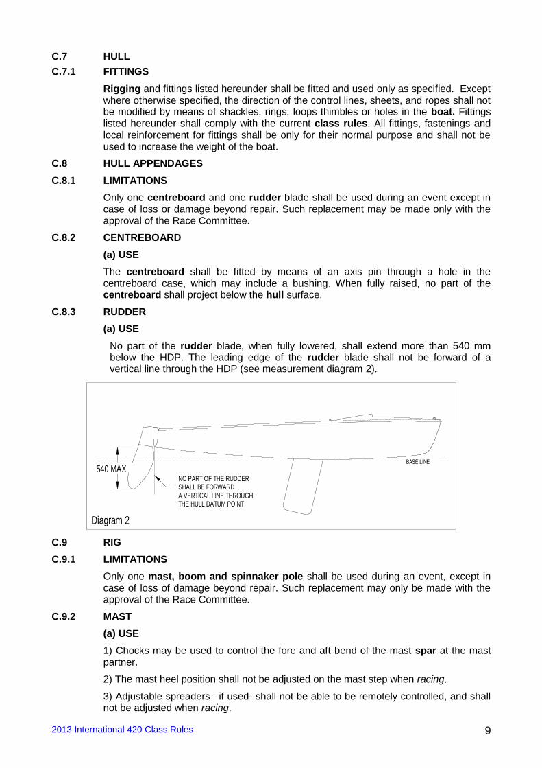
No part of the rudder blade, when fully lowered, shall extend more than 540 mm below the HDP. The leading edge of the rudder blade shall not be forward of a vertical line through the HDP (see measurement diagram 2).
540 MAX NO PART OF THE RUDDER SHALL BE FORWARD A VERTICAL LINE THROUGH
Diagram 2
BASE LINE
THE HULL DATUM POINT
C.9 RIG
C.9.1 LIMITATIONS
Only one mast, boom and spinnaker pole shall be used during an event, except in case of loss of damage beyond repair. Such replacement may only be made with the approval of the Race Committee.
C.9.2 MAST
(a) USE
1) Chocks may be used to control the fore and aft bend of the mast spar at the mast partner.
2) The mast heel position shall not be adjusted on the mast step when racing.
3) Adjustable spreaders –if used- shall not be able to be remotely controlled, and shall not be adjusted when racing.
2013 International 420 Class Rules 10
4) The effective length of the shrouds shall not be adjusted when racing.
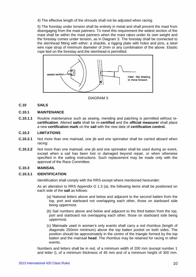
5) The forestay under tension shall be entirely in metal and shall prevent the mast from disengaging from the mast partners. To meet this requirement the widest section of the mast shall be within the mast partners when the mast rakes under its own weight and the forestay comes under tension, as in Diagram 3. The forestay shall be connected to the stemhead fitting with either: a shackle, a rigging plate with holes and pins, a steel wire rope strop of minimum diameter of 2mm or any combination of the above. Elastic rope tied on the forestay and the stemhead is permitted.
DIAGRAM 3
C.10 SAILS
C.10.1 MAINTENANCE
C.10.1.1 Routine maintenance such as sewing, mending and patching is permitted without re-certification. Altered sails shall be re-certified and the official measurer shall place a new certification mark on the sail with the new date of certification control.
C.10.2 LIMITATIONS
C.10.2.1 Not more than one mainsail, one jib and one spinnaker shall be carried aboard when racing.
C.10.2.2 Not more than one mainsail, one jib and one spinnaker shall be used during an event, except when a sail has been lost or damaged beyond repair, or when otherwise specified in the sailing instructions. Such replacement may be made only with the approval of the Race Committee.
C.10.3 MAINSAIL
C.10.3.1 IDENTIFICATION
Identification shall comply with the RRS except where mentioned hereunder:
As an alteration to RRS Appendix G 1.3 (a), the following items shall be positioned on each side of the sail as follows:
(a) National letters above and below and adjacent to the second batten from the top, port and starboard not overlapping each other, those on starboard side being uppermost.
(b) Sail numbers above and below and adjacent to the third batten from the top, port and starboard not overlapping each other, those on starboard side being uppermost.
(c) Mainsails used in women’s only events shall carry a red rhombus (length of diagonals 250mm minimum) above the top batten pocket on both sides. The position should be approximately in the centre of the triangle formed by the top batten and the mainsail head. The rhombus may be retained for racing in other events.
Numbers and letters shall be in red, of a minimum width of 200 mm (except number 1 and letter I), of a minimum thickness of 45 mm and of a minimum height of 300 mm.
2013 International 420 Class Rules 11
Other dimensions and indications regarding letters and numbers are specified in RRS Appendix G.1.2 (b).
All numbers, letters and the emblem shall be of paint or other, securely attached durable material.
C.10.3.2 USE
C.10.3.2.1 The sail shall be hoisted on a halyard. The arrangement shall permit hoisting and lowering of the sail while afloat with the boat upright.
C.10.3.2.2 The sail shall be set so that the highest visible point of it, projected at 90° to the mast spar, shall not be higher than the upper point, and the aft-most visible part of the leech, projected at 90° to the boom spar, is forward of the outer point on the boom.
C.10.3.2.3 Luff and foot bolt ropes shall be in the respective spar grooves or tracks.
C.10.4 JIB
C.10.4.1 USE
The sail shall be hoisted on a halyard. The arrangement shall permit hoisting and lowering of the sail while afloat with the boat upright.
C.10.4.2 Only one steel luff wire of minimum diameter of 2mm shall be fitted inside the jib luff sleeve when racing.
C.10.5 SPINNAKER
C.10.5.1 Identification
Identification shall comply with RRS, except where mentioned hereunder:
As an alteration to RRS Appendix G 1.3 (d), national letters are optional.
If positioned, national letters may be in line with the sail numbers. The colour of letters and numbers is optional, but they shall be all of the same colour, fully painted, and shall contrast with the colour of the panel to which they are positioned, of a minimum width of 200 mm (except number 1 and letter I), of a minimum thickness of 45 mm and of a minimum height of 300 mm. Other dimensions and indications regarding letters and numbers are specified in RRS.
All numbers and letters shall be of paint or other, securely attached durable material. Numbers and letters, if on both sides, shall not overlap and shall be placed at different heights with a minimum space of 60 mm.
C.10.5.2 USE
The sail shall be hoisted on a halyard. The arrangement shall permit hoisting and lowering of the sail while afloat with the boat upright.
2013 International 420 Class Rules 12
Section D – HULL AND DECK
D.1 CERTIFICATION
D.1.1 Only an official measurer shall measure the hull and sign the declaration on the IMF that it complies with the class rules, lines plan and building specification (Drawing 5). Measurements to ensure the conformity of the hull are specified on the IMF but the intention is that beyond these measurements, the hull shall completely conform to the Official Documents.
D.1.2 To be certified in conformity with the class rules, Lines Plan and Building specification (Drawing N° 5) the hull shall comply with the official documents in force at the time of initial certification measurement.
D.1.3 Measurement shall be carried out in accordance with the current version of the ERS.
D.1.4 Templates used for certification measurement of hull shall be supplied by the ISAF. Tolerances are only given to allow minor building errors and shall not be deliberately used to alter the design. The boat, before leaving the builder’s premises shall be measured by an official measurer. The measurer shall report on the IMF what he considers being a departure from the intended nature and design of the boat, and the measurement certificate may be refused.
D.1.5 No boat shall leave the builders’ premises without the ICA plaque and the builder's plaque affixed. The builder's Plaque shall mention:
- The trade mark of the boat
- The name and the address of the builder
- The year of building.
The ICA plaque shall mention:
- The ISAF logo
- The ICA logo
- The sail number allocated to the boat
The ICA plaque shall be affixed on the starboard side tank, close to the transom and the builder's plaque on the inside transom (see also rules B.4 and B.5)
D.2 BUILDERS
D.2.1 International 420 hulls shall be moulded and assembled only by licensed builders. Application for a licence shall be made to the ISAF which shall consult with the ICA and the MNA of the country where the builder has its yard before granting a license. Hulls shall be supplied only as permanently assembled boat units. Rigs, sails, hull appendages and fittings may be produced by any manufacturer.
D.2.2 Licensed builders have the sole responsibility that their production moulds, plugs and assembled boats comply with the relevant class rules and official documents.
D.2.3 If a builder does not comply with the requirements quoted in the class rules and the Official documents, the ISAF may revoke the license on the recommendation of the ICA.
D.2.4 If a builder is found to have supplied a boat that does not comply with the rules in application, he shall be liable to rectify the error, and may have his license as a builder withdrawn.
D.3 BUILDING AND MATERIALS FOR BUILDING
D.3.1 The hull shall be built in conformity with the building specifications (Drawing N° 5)
D.3.2 Materials used for building shall be those specified on the Building specification (Drawing N°5).
2013 International 420 Class Rules 13
D.3.3 No less than 0.05 m3 of positive buoyancy shall be securely attached in each side tank to give approximately equal buoyancy laterally and longitudinally. The buoyancy shall be of closed cell rigid foam, or alternatively of air containers of not less than two litres each. It shall not be used as reinforcement.
D.3.4 Non-slip material, tape and low-friction material not exceeding 4mm in thickness may be added to the hull as long as it does not change the stiffness of the hull.
D.4 ASSEMBLED HULL
D.4.1 DIMENSIONS AND MEASUREMENT
D.4.1.1 The hull datum point (HDP) is the intersection on the hull centre plane of the transom external surface with the underside of the hull surface, both extended as necessary. The aft measuring point (AMP) is the projection of the HDP on the baseline.
D.4.1.2 For fundamental measurement of boats built by current fully licensed builders after the 1st July 2007 the base line shall be set at 200 mm below the HDP and 92 mm below the keel at 3780 mm from the HDP. For new builders the effective date is 1st March 2006. Current licensed builders may also use this system before July 1st 2007. All measurements carried out from the HDP shall be made parallel to the baseline and depth measurements perpendicular to the base line. Measurement sections shall be perpendicular to the base line.
D.4.1.3 The hull length shall be minimum 4180 mm and maximum 4220 mm.
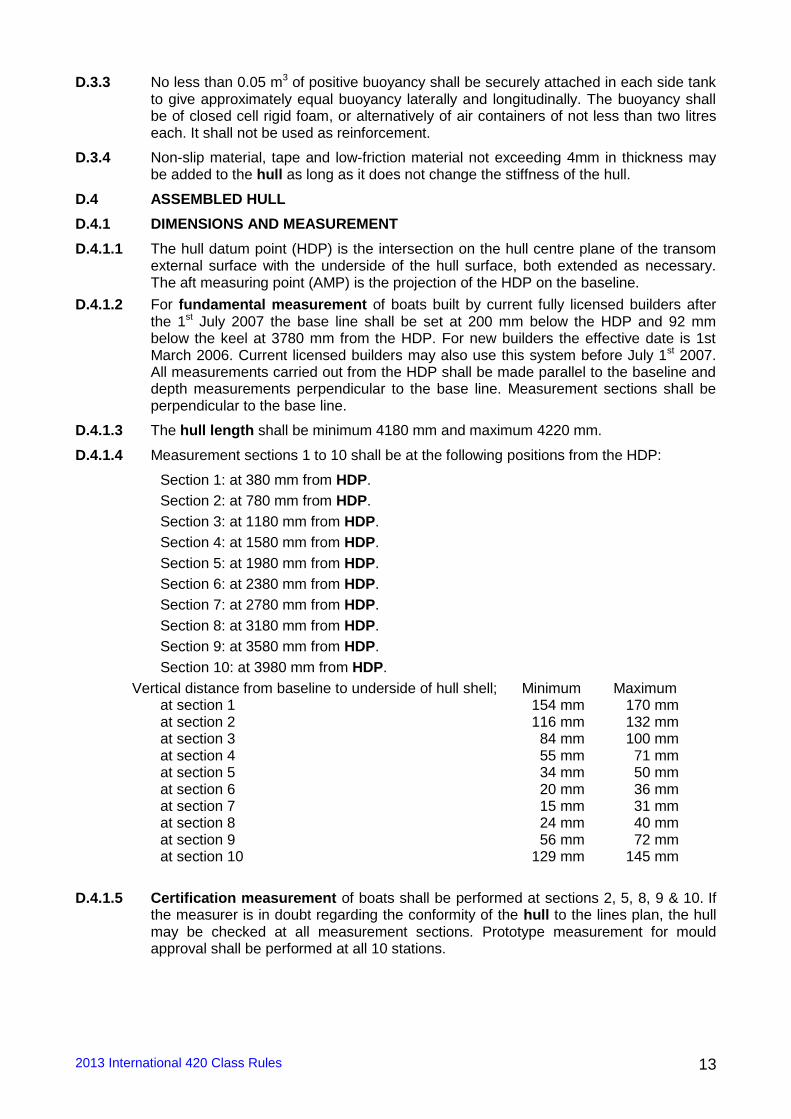
D.4.1.4 Measurement sections 1 to 10 shall be at the following positions from the HDP:
Section 1: at 380 mm from HDP.
Section 2: at 780 mm from HDP.
Section 3: at 1180 mm from HDP.
Section 4: at 1580 mm from HDP.
Section 5: at 1980 mm from HDP.
Section 6: at 2380 mm from HDP.
Section 7: at 2780 mm from HDP.
Section 8: at 3180 mm from HDP.
Section 9: at 3580 mm from HDP.
Section 10: at 3980 mm from HDP.
Vertical distance from baseline to underside of hull shell; Minimum Maximum at section 1 154 mm 170 mm at section 2 116 mm 132 mm at section 3 84 mm 100 mm at section 4 55 mm 71 mm at section 5 34 mm 50 mm at section 6 20 mm 36 mm at section 7 15 mm 31 mm at section 8 24 mm 40 mm at section 9 56 mm 72 mm at section 10 129 mm 145 mm
D.4.1.5 Certification measurement of boats shall be performed at sections 2, 5, 8, 9 & 10. If the measurer is in doubt regarding the conformity of the hull to the lines plan, the hull may be checked at all measurement sections. Prototype measurement for mould approval shall be performed at all 10 stations.
2013 International 420 Class Rules 14
BASELINE
Aft Measurement
Point
116 min 132 max 34 min
50 max 24 min 40 max
200
56 min 72 max
POSITION OF THE MEASUREMENT SECTIONS
3580
3980 3780
3180 1980 780
92
Hull Datum
Point
Forward Measurement Point
2 5 8 9 10
Diagram 4
129 min 145 max
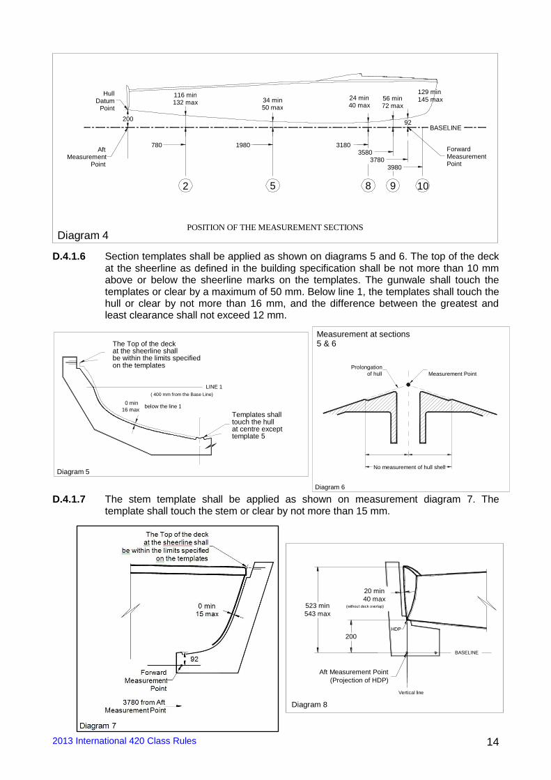
D.4.1.6 Section templates shall be applied as shown on diagrams 5 and 6. The top of the deck at the sheerline as defined in the building specification shall be not more than 10 mm above or below the sheerline marks on the templates. The gunwale shall touch the templates or clear by a maximum of 50 mm. Below line 1, the templates shall touch the hull or clear by not more than 16 mm, and the difference between the greatest and least clearance shall not exceed 12 mm.
LINE 1
The Top of the deck
( 400 mm from the Base Line)
Templates shall
at the sheerline shall be within the limits specified on the templates
touch the hull at centre except template 5
Diagram 5
0 min 16 max
below the line 1
D.4.1.7 The stem template shall be applied as shown on measurement diagram 7. The template shall touch the stem or clear by not more than 15 mm.
No measurement of hull shell
Prolongation
of hull Measurement Point
Measurement at sections 5 & 6
Diagram 6
BASELINE
20 min 40 max
Aft Measurement Point (Projection of HDP)
Vertical line
(without deck overlap)
200
523 min 543 max
HDP
Diagram 8
2013 International 420 Class Rules 15
D.4.1.8 The transom template shall be applied as shown on measurement diagram 8. The distance between the transom and the template shall be minimum 20 mm and maximum 40 mm except at the deck overlap.
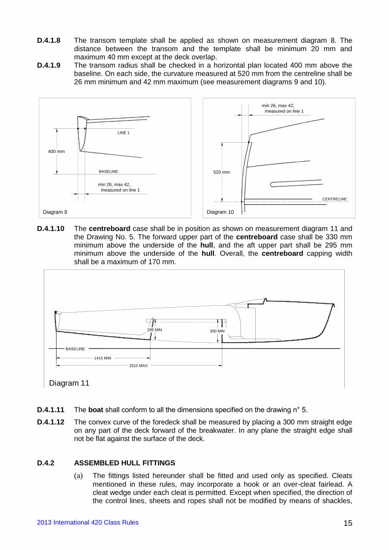
D.4.1.9 The transom radius shall be checked in a horizontal plan located 400 mm above the baseline. On each side, the curvature measured at 520 mm from the centreline shall be 26 mm minimum and 42 mm maximum (see measurement diagrams 9 and 10).
D.4.1.10 The centreboard case shall be in position as shown on measurement diagram 11 and the Drawing No. 5. The forward upper part of the centreboard case shall be 330 mm minimum above the underside of the hull, and the aft upper part shall be 295 mm minimum above the underside of the hull. Overall, the centreboard capping width shall be a maximum of 170 mm.
2510 MAX
330 MIN 295 MIN
1415 MIN
BASELINE
Diagram 11
D.4.1.11 The boat shall conform to all the dimensions specified on the drawing n° 5.
D.4.1.12 The convex curve of the foredeck shall be measured by placing a 300 mm straight edge on any part of the deck forward of the breakwater. In any plane the straight edge shall not be flat against the surface of the deck.
D.4.2 ASSEMBLED HULL FITTINGS
(a) The fittings listed hereunder shall be fitted and used only as specified. Cleats
mentioned in these rules, may incorporate a hook or an over-cleat fairlead. A cleat wedge under each cleat is permitted. Except when specified, the direction of the control lines, sheets and ropes shall not be modified by means of shackles,
BASELINE
LINE 1
400 mm
min 26, max 42, measured on line 1
Diagram 9
520 mm
CENTRELINE
measured on line 1 min 26, max 42,
Diagram 10
2013 International 420 Class Rules 16
rings, loops or holes in the boat. Control lines, ropes, sheets, halyards shall not pass through the buoyancy tanks and/or the breakwater.
(b) No fittings, with the exception of: spinnaker sheet catcher(s), non-slip material on the gunwale, rudder fittings and transom drainage flaps shall project beyond the outboard edges of the gunwale or beyond the profile of the hull.
(c) No fitting shall serve as an extension of the hull surface.
(d) Ballast shall not be carried.
(e) Materials for permitted fittings are optional except that Titanium is prohibited.
D.4.2.1 MANDATORY, WITH POSITION OR DIMENSION SPECIFIED
The following fittings shall be positioned in accordance with the drawing N°5 and shall be used as specified
(a) One stem-head fitting for attachment of the forestay and the headsail. The centre of the front hole of the stem-head fitting shall be at 4085 mm minimum and 4125 mm maximum from the HDP. Only one hole for the forestay and one hole for the headsail are permitted. The forestay shall be attached to the front hole and the headsail shall be attached to the aft hole.
(b) Two shroud plates for the shrouds, one for each side of the boat. The centre of the hole of the shroud plates measured on the centreline shall be at 2550 mm minimum and 2570 mm maximum from the HDP.
(c) One mainsheet track or bar of any profile, made only of metal or GRP. It shall be straight and fixed to the centreboard case capping. The track or bar shall have a maximum height of 40 mm and a maximum width of 40 mm. The centreline of the track or bar shall be fixed to the side tanks at 1400 mm minimum and 1500 mm maximum from the HDP.
(d) One mast step fixed on the keelson. The length of the mast step shall be 150 mm maximum. The forward part of the mast step shall be at 2890 mm minimum and 2910 mm maximum from the HDP. The bearing surface of the mast step shall be at 5 mm maximum from the top surface of the keelson.
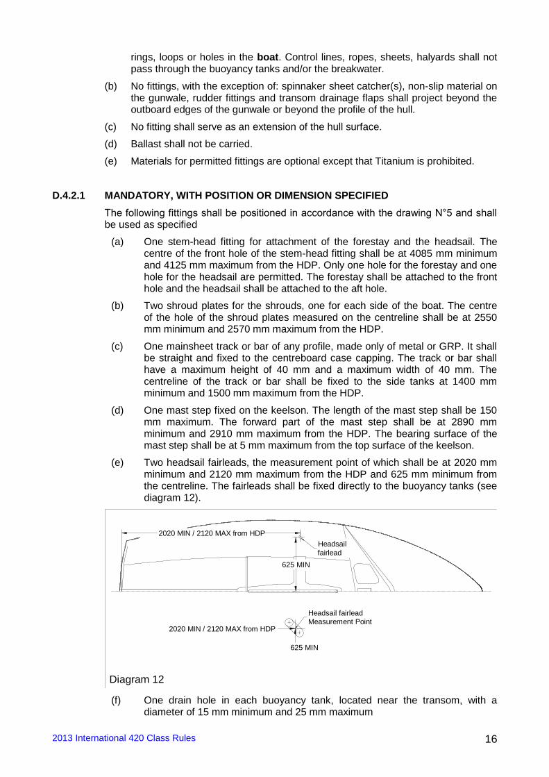
(e) Two headsail fairleads, the measurement point of which shall be at 2020 mm minimum and 2120 mm maximum from the HDP and 625 mm minimum from the centreline. The fairleads shall be fixed directly to the buoyancy tanks (see diagram 12).
625 MIN
2020 MIN / 2120 MAX from HDP
625 MIN
2020 MIN / 2120 MAX from HDP
Headsail fairlead Measurement Point
Headsail fairlead
Diagram 12
(f) One drain hole in each buoyancy tank, located near the transom, with a diameter of 15 mm minimum and 25 mm maximum
2013 International 420 Class Rules 17
(g) A minimum of one inspection hole for each buoyancy tank with a minimum diameter of 100 mm.
(h) Two spinnaker bags located according to Drawing 5.
(i) At least one draining hole or port in the transom, with a maximum total area of 80 cm². Hinged covers or other devices for closing draining ports or drain holes in the transom. These covers or devices shall not obstruct the rudder
D.4.2.2 MANDATORY, WITH POSITION OR DIMENSION OPTIONAL
(a) Mainsail, headsail and spinnaker sheets
(b) Four single-sheave blocks for the mainsheet, one of which may be a ratchet block. The mainsheet shall be attached to the block which is connected to the bridle. Two blocks shall be attached directly to the boom. The fourth block shall be fixed to a mounting on the aft part of the centreboard case capping or keelson. The maximum obtained purchase shall be 4:1.
(c) A bridle made either of
i) Two strops, either of rope or wire. Each strop shall be attached to a point on the mainsheet bar/track or its end fittings, and to the mainsheet block, so forming a triangle. Each strop may be adjustable by including one additional permanently fixed eyelet and one snap hook/shackle fixed at the track/bar or its end fittings, or
ii) Two strops of rope. The strop of each side shall pass through a sheave or block attached to the end fittings of the mainsheet track/bar, and then end in a cleat without moving parts, fixed on the mainsheet track/bar. One sheave and one cleat per side are the only fittings permitted.
Any other adjustment system is prohibited.
(d) One kicking strap of rope and/or stainless steel wire with a maximum of five single-sheave blocks. One cleat without moving parts and one guiding block directly behind the cleat for the kicking strap system.
(e) Two rudder fittings (pintles or gudgeons) for the rudder.
(f) One swivelling cleat with moving parts fixed on the aft part or the centreboard case capping or two cleats with moving parts on the side tanks for the mainsheet.
(g) Two cleats with moving parts, fixed on the side tanks, for the headsail sheets.
(h) Two cleats without moving parts, fixed on the side tanks, for the spinnaker sheets.
(i) One fairlead and one cleat with or without moving parts for the spinnaker halyard.
(j) One cleat without moving parts and one guiding block directly behind the cleat for the spinnaker uphaul/downhaul system (adjusting the height of the spinnaker pole). An additional block, a rope and a device to attach the rope is permitted between the mast and the cleat mentioned above. Mast fittings for the spinnaker pole uphaul/downhaul are mentioned in F 2.6.15.
(l) A maximum of four fairleads (also mentioned in F.5.1.2) for the elastic cord of the two trapeze wires
(m) Two spinnaker fairleads or blocks for the spinnaker sheets.
2013 International 420 Class Rules 18
D.4.2.3 OPTIONAL
The following fittings -if fitted- shall be used only as specified below:
(a) One self-bailer
(b) Toe straps inside the cockpit area for the crew, adjustable by means of ropes and knots or one cleat without moving parts, and elastic cord to keep them lifted up.
(c) Spinnaker catcher fitting(s) which shall not project outside the gunwale edges or more than 150 mm beyond the bow.
(d) One hook on each side of the boat, on shrouds/shroud plates or fixed on the deck and at 100 mm maximum forward of the centre of the hole of the shroud plates, to lead the spinnakers sheets aft.
(e) One device on each side of the boat for securing the spinnaker halyard while the spinnaker is not set
(f) Tubular covers at the lower end of shrouds or their adjusters and one for the lower end of the forestay to ease the passage of the sheets and to prevent snagging.
(g) Stainless steel springs under blocks to prevent them from falling over.
(h) One non-electrical wind indicator at the mast head.
(i) Sealing strips for the centreboard slot of optional material.
(k) Strips of a minimum length of 300mm to reduce friction and/or the distance between the centreboard and centreboard case, but no device shall be attached to the inside of the centreboard case that could cause the centreboard to gybe (angle to windward).
(l) A moulded insert in the thwart or a device to secure the spinnaker pole in the cockpit.
m) Headsail tack adjustment system, consisting of a shackle on the stemhead fitting, one cleat without moving parts mounted on the foredeck, one fairlead directly behind the cleat and a single piece of rope.
(n) One Cunningham control system of rope with a maximum of two single-sheave blocks. One cleat without moving parts and one guiding block directly behind the cleat for the mainsail Cunningham line on the centerboard case capping
D.5 HULL WEIGHT
The hull weight, including stem head fitting, shroud plates without shroud adjusters, all fixed fittings, complete hiking straps, rudder pintles or gudgeons, bailer, mainsheet track/bar, centreboard pivot pin, inspection hole covers, spinnaker bags and corrector weights, but excluding the, mast, boom, spinnaker pole, centreboard, the control lines, sheets, the rudder, portable equipment and the towing rope shall be 80 kg minimum in dry condition.
D.6 HULL CORRECTOR WEIGHTS
If the hull weight according to D.5 is found to be less than 80 kg, corrector weights of a maximum total weight of 2 kg shall be bolted to the upper inside surface of the transom. The number and total of correctors shall be recorded on the IMF and the measurement certificate. Corrector weights shall not be removed or altered without the hull being re-weighted by an official measurer.
2013 International 420 Class Rules 19
Section E - CENTREBOARD, RUDDER AND TILLER
E.1 MEASUREMENT
Centreboard and rudder shall comply with the current class rules.
E.2 CENTREBOARD
E.2.1 The centreboard shall be of even thickness, minimum 16 mm and maximum 20 mm throughout, except that it may be bevelled to a maximum distance of 105 mm from the edges. Except for permitted bevelling, the thickness shall not vary by more than 1 mm.
E.2.2 The centreboard shall be made from one or a combination of the following materials; wood, plywood, polyester resin reinforced with glass fibre, epoxy reinforced with glass fibre and/or plastic foam which includes micro-balloons and may be painted.
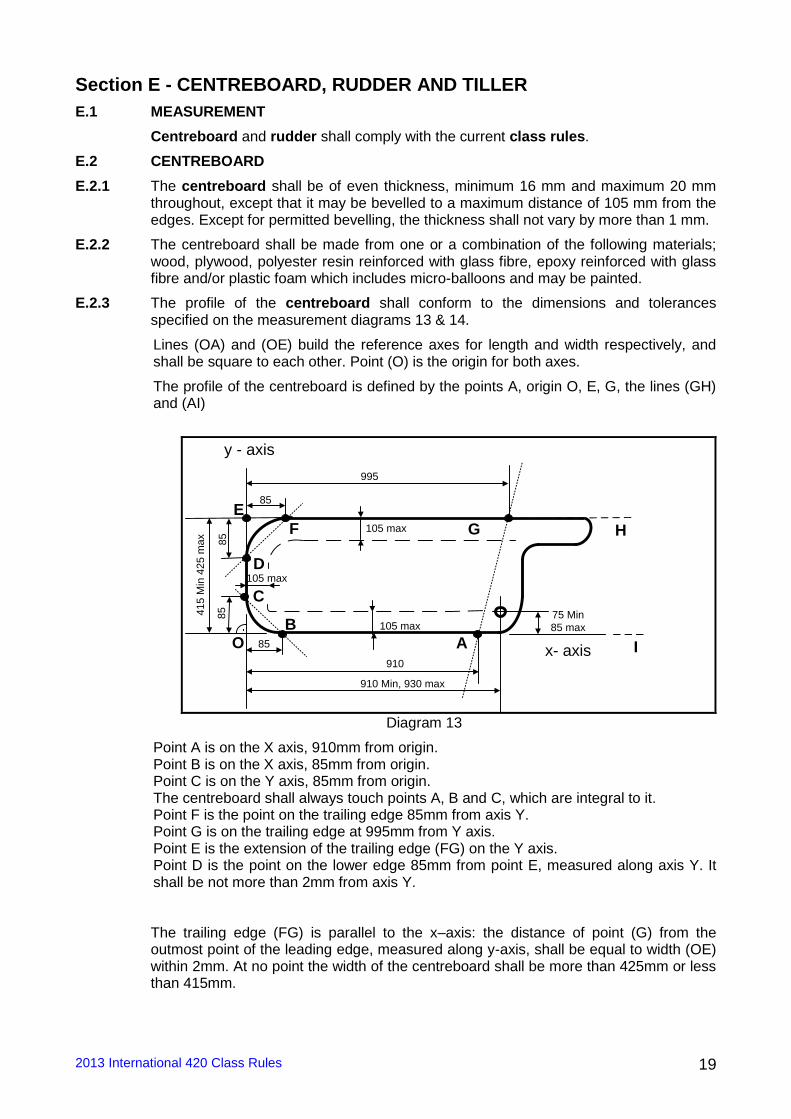
E.2.3 The profile of the centreboard shall conform to the dimensions and tolerances specified on the measurement diagrams 13 & 14.
Lines (OA) and (OE) build the reference axes for length and width respectively, and shall be square to each other. Point (O) is the origin for both axes.
The profile of the centreboard is defined by the points A, origin O, E, G, the lines (GH) and (AI)
75 Min
85 max
995
105 max
41
5 M
in 4
25
ma
x
85
85
85
85E
G
105 max
910 Min, 930 max
AB
C
D
F
910
O
y - axis
x- axis
H
I
105 max
Diagram 13
Point A is on the X axis, 910mm from origin. Point B is on the X axis, 85mm from origin. Point C is on the Y axis, 85mm from origin. The centreboard shall always touch points A, B and C, which are integral to it. Point F is the point on the trailing edge 85mm from axis Y. Point G is on the trailing edge at 995mm from Y axis. Point E is the extension of the trailing edge (FG) on the Y axis. Point D is the point on the lower edge 85mm from point E, measured along axis Y. It shall be not more than 2mm from axis Y. The trailing edge (FG) is parallel to the x–axis: the distance of point (G) from the outmost point of the leading edge, measured along y-axis, shall be equal to width (OE) within 2mm. At no point the width of the centreboard shall be more than 425mm or less than 415mm.
2013 International 420 Class Rules 20
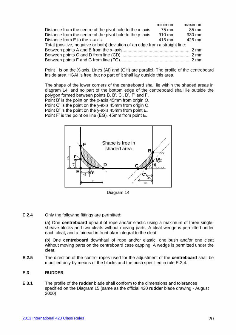
minimum maximum Distance from the centre of the pivot hole to the x–axis 75 mm 85 mm Distance from the centre of the pivot hole to the y–axis 910 mm 930 mm Distance from E to the x–axis 415 mm 425 mm Total (positive, negative or both) deviation of an edge from a straight line: Between points A and B from the x–axis ......................................... ............. 2 mm Between points C and D from line (CD) .......................................... ............. 2 mm Between points F and G from line (FG) ........................................... ............. 2 mm Point I is on the X-axis. Lines (AI) and (GH) are parallel. The profile of the centreboard inside area HGAI is free, but no part of it shall lay outside this area. The shape of the lower corners of the centreboard shall lie within the shaded areas in diagram 14, and no part of the bottom edge of the centreboard shall lie outside the polygon formed between points B, B’, C’, D’, F’ and F. Point B’ is the point on the x-axis 45mm from origin O. Point C’ is the point on the y-axis 45mm from origin O. Point D’ is the point on the y-axis 45mm from point E. Point F’ is the point on line (EG), 45mm from point E.
Shape is free in
shaded area
85
45
45
45
85
B
E
85
45
85
CD
F
F'B'
C'D'
Diagram 14
E.2.4 Only the following fittings are permitted:
(a) One centreboard uphaul of rope and/or elastic using a maximum of three single-sheave blocks and two cleats without moving parts. A cleat wedge is permitted under each cleat, and a fairlead in front of/or integral to the cleat.
(b) One centreboard downhaul of rope and/or elastic, one bush and/or one cleat without moving parts on the centreboard case capping. A wedge is permitted under the cleat.
E.2.5 The direction of the control ropes used for the adjustment of the centreboard shall be modified only by means of the blocks and the bush specified in rule E.2.4.
E.3 RUDDER
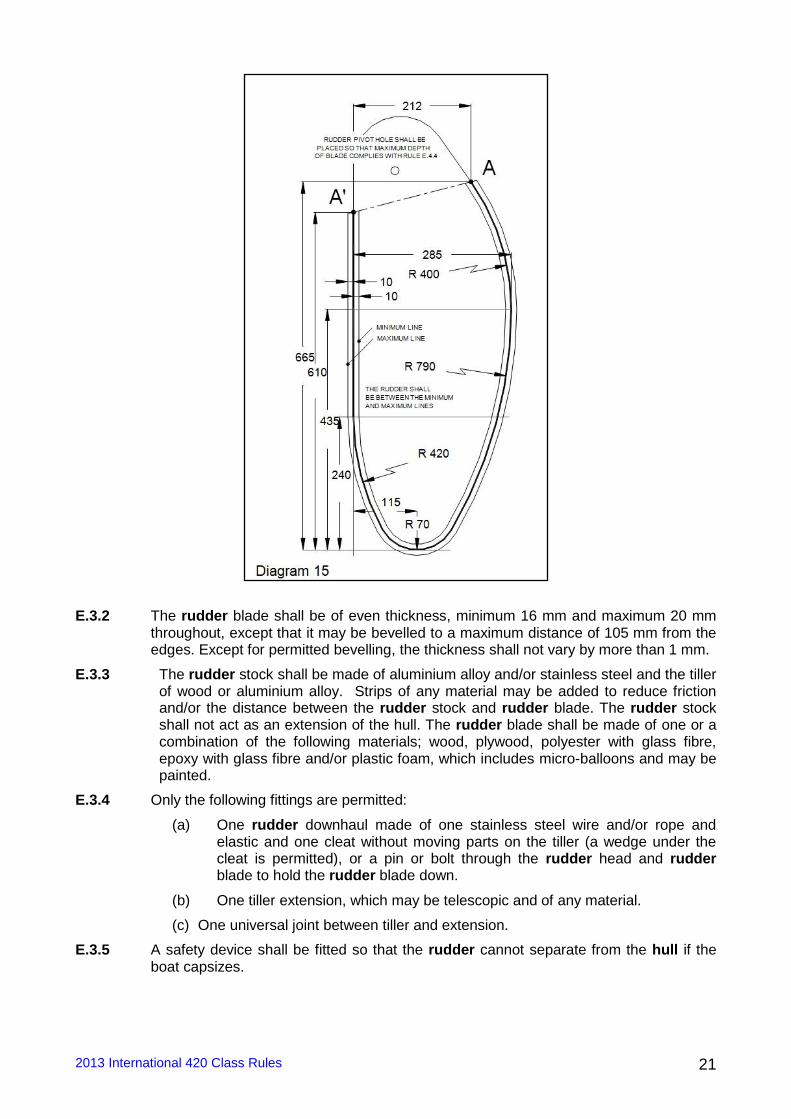
E.3.1 The profile of the rudder blade shall conform to the dimensions and tolerances
specified on the Diagram 15 (same as the official 420 rudder blade drawing - August 2000)
2013 International 420 Class Rules 21
E.3.2 The rudder blade shall be of even thickness, minimum 16 mm and maximum 20 mm
throughout, except that it may be bevelled to a maximum distance of 105 mm from the edges. Except for permitted bevelling, the thickness shall not vary by more than 1 mm.
E.3.3 The rudder stock shall be made of aluminium alloy and/or stainless steel and the tiller of wood or aluminium alloy. Strips of any material may be added to reduce friction and/or the distance between the rudder stock and rudder blade. The rudder stock shall not act as an extension of the hull. The rudder blade shall be made of one or a combination of the following materials; wood, plywood, polyester with glass fibre, epoxy with glass fibre and/or plastic foam, which includes micro-balloons and may be painted.
E.3.4 Only the following fittings are permitted:
(a) One rudder downhaul made of one stainless steel wire and/or rope and elastic and one cleat without moving parts on the tiller (a wedge under the cleat is permitted), or a pin or bolt through the rudder head and rudder blade to hold the rudder blade down.
(b) One tiller extension, which may be telescopic and of any material.
(c) One universal joint between tiller and extension.
E.3.5 A safety device shall be fitted so that the rudder cannot separate from the hull if the boat capsizes.
2013 International 420 Class Rules 22
Section F - RIG
F.1 MEASUREMENT
Measurement shall be carried out in accordance with the ERS.
F.2 MAST
F.2.1 MEASUREMENT
The mast and its fittings shall comply with the current class rules.
F.2.3 MANUFACTURER
Manufacturer is optional.
F.2.4 MATERIALS
The mast spar shall be of aluminium alloy. It may be anodised or painted.
F.2.5 CONSTRUCTION
The mast shall include a fixed sail groove or track, which may or may not be integral to the spar but shall be of aluminium. Rotating and permanently bent masts are prohibited but a mast spar curvature measured at any place of the mast between the upper and lower points, of a maximum of 40 mm is permitted.
F.2.6 FITTINGS
The following fittings are mandatory and shall be used as specified:
F.2.6.1 A mast head fitting which may include the upper sheave for the mainsail halyard.
F.2.6.2 One halyard for the mainsail, one halyard for the headsail and one halyard for the spinnaker. The end of the spinnaker halyard may be fitted with an elastic cord. The direction of the halyards shall be modified only by means of the blocks, sheaves or fairleads specified in Section F of the class rules.
F.2.6.3 One lock near the masthead or one lock, cleat or rack below the gooseneck for the mainsail halyard.
F.2.6.4 A maximum of two blocks, sheaves, or fairleads for each halyard (mainsail, headsail, spinnaker). These blocks or sheaves shall be fixed on the spar.
F.2.6.5 The upper headsail halyard sheave, block or fairlead shall be located below the forestay rigging point and shall be positioned so that the intersection of the mast and the lower edge of the halyard, when at 900 to the mast, and extended as necessary, shall be at the distance stated in F.2.7 (see headsail hoist height).
F.2.6.6 No part of the upper spinnaker halyard sheave, block or fairlead shall be more than 40 mm from the foreside of the mast.
F.2.6.7 Two shrouds, one forestay and two trapeze wires and the fittings to secure them to the mast. The positions of rigging points of the shrouds, forestay and trapeze wires shall be at the distances mentioned in F.2.7 (see shrouds, forestay and trapeze heights).
F.2.6.8 A pair of fixed or adjustable metal spreaders, with optional attachment systems. The spreader height shall be at the distance stated in F.2.7. Optional devices may be attached to the spreaders and/or the rigging to prevent the spinnaker halyard from getting tangled.
F.2.6.9 One spinnaker pole fitting on the foreside of the mast, with a maximum projection of 45mm.
F.2.6.10 One gooseneck, fixed to the mast to connect the boom to the mast.
F.2.6.11 One cleat without moving parts below the gooseneck and one rope, for the mainsail
Cunningham line if the system in D.4.2.3(n) is not present.F.2.6.12 A tensioning
system for the headsail halyard made of two blocks with a maximum of six sheaves in
2013 International 420 Class Rules 23
total, and one cleat. This cleat may have moving parts and shall be fixed at one of the two blocks. The system shall be attached via a hook or a shackle to the headsail halyard, and at the other end to the mast or the mast step fitting, by means of a wire strop or shackles and an attachment to the mast (tang, mast anchor plate etc). Enclosed purchase systems such as power boxes are not permitted.
F.2.6.13 One rope or a device around the mast and through the mainsail tack cringle to secure the mainsail tack.
F.2.6.14 A protection around the mast where it touches the mast gate
F.2.6.15 One spinnaker pole uphaul / downhaul made of rope and elastic and one hook. The spinnaker pole uphaul / downhaul may be fitted with two plastic balls. For the adjustment of the spinnaker pole uphaul / downhaul, only the following fitting is permitted, one eye or block on the foreside of the mast, located below the forestay and shroud attachment. One eye or block or one hole/bush in the mast partner at the foreside of the mast at the level of the mast partner. One block, sheave, or one fairlead at the bottom of the mast. (Additional fittings for the spinnaker pole uphaul/downhaul are stated in D.4.2.2.(j)).
F.2.6.16 One kicking-strap attachment fitting
F.2.6.17 A mast heel fitting which may include the lower sheaves for the halyards and spinnaker pole uphaul / downhaul.
F.2.6.18 Permanently painted / taped limit marks in a contrasting colour.
F.2.6.19 A device for preventing the mainsail from being set above the upper point, to ensure compliance with C.10.3.2.2
F.2.7 DIMENSIONS
Unless otherwise specified, all longitudinal measurements shall be carried out from the mast datum point. For this purpose, the mast datum point (MDP) is located at the mast heel point.
minimum maximum
Mast length 6260 mm
Fore and aft mast spar cross section between 1550 mm and 4500 mm from the MDP
50 mm 75 mm
Transverse mast spar cross section within 4500 mm from MDP
45 mm 75 mm
Mast limit marks width 10 mm
Lower point height 1160 mm
Upper point height from lower point 4900 mm
Headsail Hoist Height 4520 mm (see F.2.6.5)
Spinnaker hoist height 4650 mm
Shrouds, forestay and trapeze heights 4550 mm 4650 mm
Spreader height 2550 mm 2650 mm
F.2.8 WEIGHT
The mast weight, with fittings specified in F.2.6 but without the tensioning system mentioned in F.2.5.12 and the rope mentioned in F.2.5.13, and including fittings specified in F.5.1 without the elastic cord and the four fairleads stated in F.5.1.2 and with the length of elastic at the level of the spreaders as stated in F.5.1.2, shall be not less than 7.5 kg.
F.2.9 The centre of gravity of the mast, including fittings and rigging listed in F.2.8 with the shrouds, forestay, trapeze wires and halyards secured along the mast, shall be at 2400 mm minimum from the mast datum point. For the measurement, the halyards shall be hoisted and the halyard tails outside the mast shall be kept in hand by the measurer.
2013 International 420 Class Rules 24
F.3 BOOM
F.3.1 MEASUREMENT
The boom and its fittings shall comply with the current class rules.
F.3.2 MANUFACTURER
Manufacturer is optional.
F.3.3 MATERIALS
The boom spar shall be of aluminium alloy. It may be anodised or painted.
F.3.4 CONSTRUCTION
F.3.4.1 The boom shall include a fixed aluminium sail groove or track, which may or may not be integral to the boom spar.
F.3.4.2 The boom spar shall be of the same cross section throughout and shall not be tapered.
F.3.5 FITTINGS
F.3.5.1 MANDATORY
F.3.5.1.1 A kicking-strap attachment (eye, plate, or hole through the boom)
F.3.5.1.2 Two mainsheet block attachments fittings (eyes, plates, or holes through the boom)
F.3.5.1.3 A gooseneck attachment
F.3.5.1.4 One end fitting which may incorporate one sheave. One outhaul consisting of rope, a maximum of one block, one cleat without moving parts and optional elastic cord. A guiding block directly behind the cleat may be used.
F.3.5.1.5 A device for preventing the mainsail from being set outside the outer point, to ensure compliance with C.10.3.2.2
F.3.5.1.6 Permanently painted / taped outer limit mark in a contrasting colour.
F.3.5.2 OPTIONAL
F.3.5.2.1 Ropes or devices through the cringles and around the boom to secure the mainsail at the clew point and the tack point.
F.3.5.2.2 Protections where the boom touches the shrouds, of any material (maximum length / height / thickness = 100 mm /50 mm /5 mm)
F.3.6 DIMENSIONS
minimum maximum
Vertical boom spar cross section 55 mm 89 mm
Transverse boom spar cross section 32 mm 76 mm
Boom limit mark width 10 mm
Outer point distance 2400 mm
F.4 SPINNAKER POLE
F.4.1 MEASUREMENT
The spinnaker pole and its fittings shall comply with the current class rules
F.4.2 MANUFACTURER
Manufacturer is optional
F.4.3 MATERIALS
The spinnaker pole spar shall be made of aluminium.
2013 International 420 Class Rules 25
F.4.4 FITTINGS
Only the following fittings are permitted: (a) End fittings and control line which may incorporate knots, toggles or short
tubes for easier handling. (b) Fittings approximately at the midpoint for attachment for uphaul/downhaul.
F.4.5 DIMENSIONS
The maximum spinnaker pole length is 1750 mm.
F.5 RIGGING AND FITTINGS
F.5.1 RIGGING
The standing rigging shall comply with the current class rules. Certification is not required. The following rigging shall be used, and consist of only:
F.5.1.1 A forestay and one shroud on each side, to support the mast. These shall be of steel wire rope with a minimum diameter of 2 mm. Rod rigging is prohibited.
F.5.1.2 One steel trapeze wire, with a minimum diameter of 2 mm, on each side for the use of one person only. Each trapeze adjustment system shall be provided with a maximum of one handhold, two sheaves, rings or hooks, an elastic cord, one rope, and one cleat. The trapeze wires may be substituted with rope for a maximum length of 500mm from the handhold. The two trapezes shall be connected to the boat by elastic cord with a maximum of four fairleads as stated in D.4.2.2.(l). A length of elastic is permitted to keep the trapeze wires clear of the spreaders. Self-tacking trapeze systems are not allowed.
F.5.2 FITTINGS
F.5.2.1 Each shroud shall be attached to the shroud plates by means of plates having rows of adjustment holes and pins. No other method of shroud adjustment is permitted.
2013 International 420 Class Rules 26
Section G – SAILS
G.1. MEASUREMENT
G.1.1 Measurement shall be carried out in accordance with the current ERS.
G.1.2 Unless otherwise specified in these rules, sails shall comply with the current class rules.
G.1.3 Headsails may be measured with battens inside the batten pockets.
G.2 CERTIFICATION
G.2.1 The official measurer shall certify mainsails and headsails at the tack, and spinnakers at the head, and shall sign and date the certification mark. The mainsail and the spinnaker may be certified without letters and numbers, but they shall comply when racing with Class rule C.10.3.1 and C.10.5.1)
G.2.2 An ISAF In-House Certification (IHC) Authorizing Authority may appoint one or more In-House Official Measurers at a sailmaker to measure and certify sails produced by that manufacturer in accordance with the ISAF guidelines.
G.2.3 For the mainsail and jib, the weight in g/m2 of the body of the sail shall be indelibly marked near the head point by the sailmaker together with the date and his signature or stamp.
G.2.4 SAILMAKER
Sailmaker is optional.
G.3 MAINSAIL
G.3.1 EMBLEM
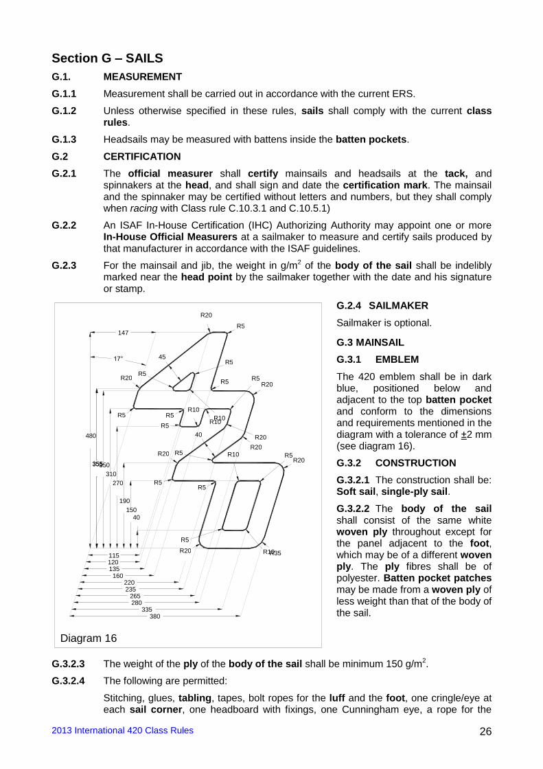
The 420 emblem shall be in dark blue, positioned below and adjacent to the top batten pocket and conform to the dimensions and requirements mentioned in the diagram with a tolerance of ±2 mm (see diagram 16).
G.3.2 CONSTRUCTION
G.3.2.1 The construction shall be: Soft sail, single-ply sail.
G.3.2.2 The body of the sail shall consist of the same white woven ply throughout except for the panel adjacent to the foot, which may be of a different woven ply. The ply fibres shall be of polyester. Batten pocket patches may be made from a woven ply of less weight than that of the body of the sail.
G.3.2.3 The weight of the ply of the body of the sail shall be minimum 150 g/m2.
G.3.2.4 The following are permitted:
Stitching, glues, tabling, tapes, bolt ropes for the luff and the foot, one cringle/eye at each sail corner, one headboard with fixings, one Cunningham eye, a rope for the
480
147
115 120
160 220 235
265 280
335 380
135
355 355 350 310
270
190 150
40
17°
40
45
R20
R35 R20 R10 R5
R5 R10
R5 R5
R20 R5
R20 R20
R20 R5
R5
R10 R10
R5 R5 R5
R20 R5 R5
R10
R5 R20
Diagram 16
2013 International 420 Class Rules 27
Cunningham, batten pocket patches, batten pocket elastic, one batten pocket end cap and one batten tensioning device for the top batten pocket, one boom slide at the clew, tell tales, ICA sail button or sticker, sailmaker’s trade mark, one window.
G.3.2.5 The ICA sail button / sticker shall be fixed in the tack.
G.3.2.6 The leech shall not extend aft of straight lines between: (1) The aft head point and the intersection of the leech and the upper edge of the nearest batten pocket, (2) The intersection of the leech and the lower edge of a batten pocket and the intersection of the leech and the upper edge of an adjacent batten pocket below, (3) The clew point and the intersection of the leech and the lower edge of the nearest batten pocket.
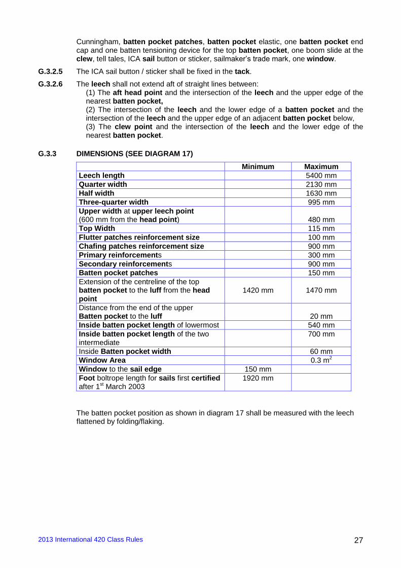
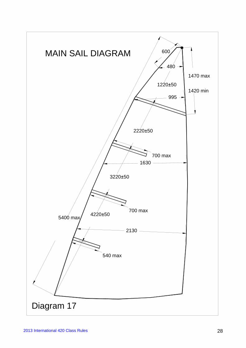
G.3.3 DIMENSIONS (SEE DIAGRAM 17)
Minimum Maximum
Leech length 5400 mm
Quarter width 2130 mm
Half width 1630 mm
Three-quarter width 995 mm
Upper width at upper leech point (600 mm from the head point)
480 mm
Top Width 115 mm
Flutter patches reinforcement size 100 mm
Chafing patches reinforcement size 900 mm
Primary reinforcements 300 mm
Secondary reinforcements 900 mm
Batten pocket patches 150 mm
Extension of the centreline of the top batten pocket to the luff from the head point
1420 mm
1470 mm
Distance from the end of the upper Batten pocket to the luff
20 mm
Inside batten pocket length of lowermost 540 mm
Inside batten pocket length of the two intermediate
700 mm
Inside Batten pocket width 60 mm
Window Area 0.3 m2
Window to the sail edge 150 mm
Foot boltrope length for sails first certified after 1st March 2003
1920 mm
The batten pocket position as shown in diagram 17 shall be measured with the leech flattened by folding/flaking.
2013 International 420 Class Rules 28
Diagram 17
480
995
1630
2130
1220±50
2220±50
4220±50
3220±50
600 MAIN SAIL DIAGRAM
540 max
700 max
700 max
1420 min
1470 max
5400 max
2013 International 420 Class Rules 29
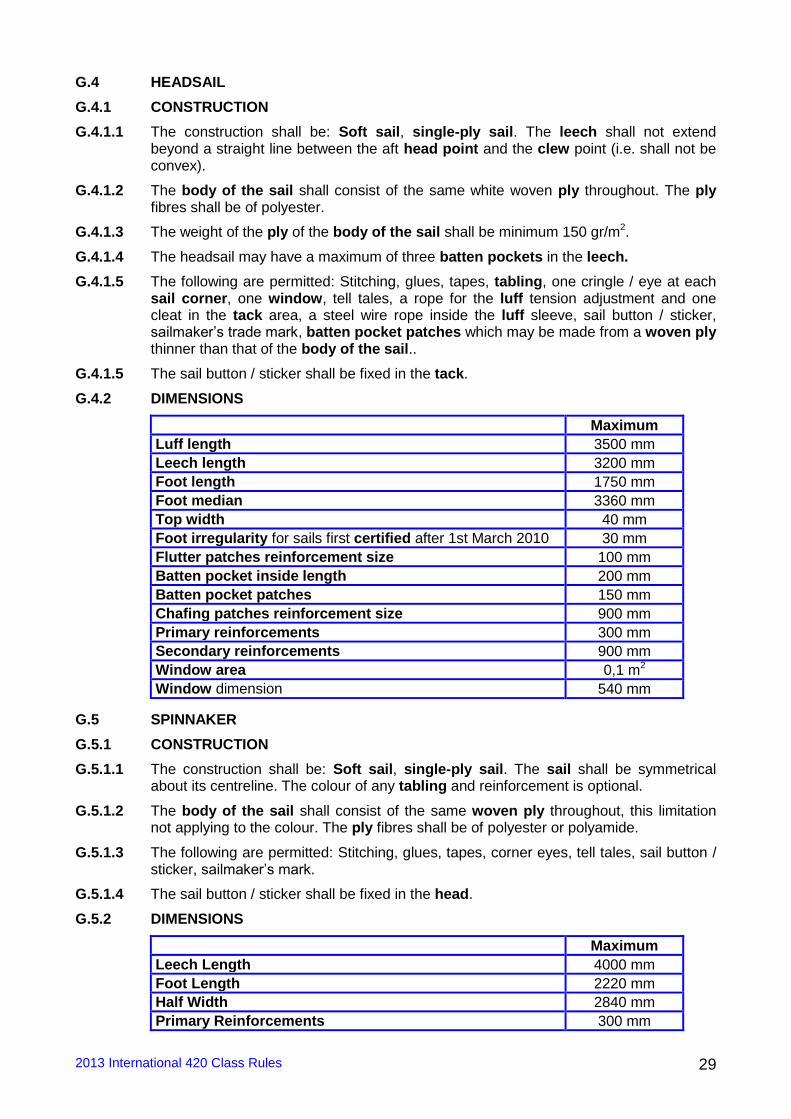
G.4 HEADSAIL
G.4.1 CONSTRUCTION
G.4.1.1 The construction shall be: Soft sail, single-ply sail. The leech shall not extend beyond a straight line between the aft head point and the clew point (i.e. shall not be convex).
G.4.1.2 The body of the sail shall consist of the same white woven ply throughout. The ply fibres shall be of polyester.
G.4.1.3 The weight of the ply of the body of the sail shall be minimum 150 gr/m2.
G.4.1.4 The headsail may have a maximum of three batten pockets in the leech.
G.4.1.5 The following are permitted: Stitching, glues, tapes, tabling, one cringle / eye at each sail corner, one window, tell tales, a rope for the luff tension adjustment and one cleat in the tack area, a steel wire rope inside the luff sleeve, sail button / sticker, sailmaker’s trade mark, batten pocket patches which may be made from a woven ply thinner than that of the body of the sail..
G.4.1.5 The sail button / sticker shall be fixed in the tack.
G.4.2 DIMENSIONS
Maximum
Luff length 3500 mm
Leech length 3200 mm
Foot length 1750 mm
Foot median 3360 mm
Top width 40 mm
Foot irregularity for sails first certified after 1st March 2010 30 mm
Flutter patches reinforcement size 100 mm
Batten pocket inside length 200 mm
Batten pocket patches 150 mm
Chafing patches reinforcement size 900 mm
Primary reinforcements 300 mm
Secondary reinforcements 900 mm
Window area 0,1 m2
Window dimension 540 mm
G.5 SPINNAKER
G.5.1 CONSTRUCTION
G.5.1.1 The construction shall be: Soft sail, single-ply sail. The sail shall be symmetrical about its centreline. The colour of any tabling and reinforcement is optional.
G.5.1.2 The body of the sail shall consist of the same woven ply throughout, this limitation not applying to the colour. The ply fibres shall be of polyester or polyamide.
G.5.1.3 The following are permitted: Stitching, glues, tapes, corner eyes, tell tales, sail button / sticker, sailmaker’s mark.
G.5.1.4 The sail button / sticker shall be fixed in the head.
G.5.2 DIMENSIONS
Maximum
Leech Length 4000 mm
Foot Length 2220 mm
Half Width 2840 mm
Primary Reinforcements 300 mm
2013 International 420 Class Rules 30
Secondary Reinforcements 900 mm
Foot Median for sails first certified after 15th March 2007 4650 mm
__________________________________________________________________
OFFICIAL DOCUMENTS:
International 420 Class Rules
Lines plan (Plan de formes) issue C (August 2004)
Building specification (Drawing N° 5) issue H (February 2009)
International 420 Rudder Blade Drawing (August 2000)
International Measurement Form (January 2013)
Official templates used for measurement: BOW (ISSUE C); C1 (ISSUE B); C2 (ISSUE B); C3 (ISSUE B); C4 (ISSUE B); C5 (ISSUE B); C6 (ISSUE B); C7 (ISSUE B); C8 (ISSUE B); C9 (ISSUE B); C10 (ISSUE B) AND STERN (ISSUE B or C).
Effective Date: 1st January 2013 Published Date: 29th November 2012
Previous issue: 27th November 2012