international building code – structural s5...
TRANSCRIPT
2007 ICC FINAL ACTION AGENDA 1
INTERNATIONAL BUILDING CODE – STRUCTURAL
S5-06/07 1604.11 (New), 1605 (New) Proposed Change as Submitted: Proponent: William M. Connolly, State of New Jersey, Department of Community Affairs, Division of Codes and Standards, representing International Code Council Ad Hoc Committee on Terrorism Resistant Buildings Add new text as follows: 1604.11 Disproportionate collapse. Design for structural integrity to protect against disproportionate collapse shall be in accordance with Section 1605. 1605 DISPROPORTIONATE COLLAPSE 1605.1 General. The building, structure or portion thereof shall be constructed so the building will not suffer collapse as the result of an accident or incident to an extent disproportionate to the cause. Buildings shall be designed for sufficient robustness to sustain a limited extent of damage or failure, depending on the class of the building, without collapse. Design of new buildings in accordance with Section 1605.5 shall be deemed to comply with Section 1605.4. 1605.2 DEFINITIONS. DISPROPORTIONATE COLLAPSE. Local failure of a member of the structural frame that leads to the collapse of the adjoining structural members, which then leads to additional collapse. LOAD-BEARING CONSTRUCTION. Load-bearing construction shall include masonry cross-wall construction and walls of lightweight steel Section studs. KEY ELEMENT. A structural element capable of sustaining an accidental design loading of 700 psf (34.5 kN/m2) applied in the horizontal and vertical directions (in one direction at a time) to the member and any attached components (ie. cladding, etc.). STRUCTURAL FRAME. The columns and the girders, beams, trusses, and spandrels having direct connections to the columns and bracing members designed to carry gravity loads. 1605.3 Building class. Buildings shall be classified in accordance with Table 1605.3. Buildings with occupancy groups within more than one classification shall be designed as the higher class.

2 2007 ICC FINAL ACTION AGENDA
TABLE 1605.3 BUILDING CLASS
CLASS BUILDING TYPE AND OCCUPANCY
1
Group I-1, R-3 or R-4 not exceeding 4 stories Agricultural buildings Unoccupied buildings that are separated from other buildings by a distance of 1.5 times the buildings height.
2
Group I-3 Group R-3 not exceeding 5 stories Group R-1 not exceeding 4 stories Group R-2 not exceeding 4 stories Group B not exceeding 4 stories Group F not exceeding 3 stories Group M not exceeding 3 stories of less than 21,500 square feet floor area in each story. Group E not exceeding one story All buildings of Group A not exceeding 2 stories which contain floor areas not exceeding 21,500 square feet at each story.
3
Group R-1 and R-2 buildings greater than 4 stories but not exceeding 15 stories Group E buildings greater than 1 story but not exceeding 15 stories. Group M buildings greater than 3 stories but not exceeding 15 stories. Group I-2 buildings not exceeding 3 stories. Group B buildings greater than 4 stories but not exceeding 15 stories. Group A buildings which contain floors of more than 21,500 square feet but less than 54,000 square feet per floor. Group S buildings not exceeding 6 stories.
4.
All buildings that exceed the limits on area or number of stories for class 1-3. Grandstands accommodating more than 5000 spectators. Building containing hazardous substances and/or processes – Groups H-1, H-2, H-3, H-4, and H-5.
1605.4 Performance design approach: Design to protect against disproportionate collapse shall be designed in accordance with accepted engineering practice to meet the requirements of this section or shall be in accordance with Section 1605.5. 1605.4.1 Class 1 buildings (performance). Class 1 buildings are not required to comply with this section. 1605.4.2 Class 2 buildings (performance). Class 2 buildings shall be provided with horizontal ties or with anchorage. 1605.4.2.1 Class 2 structural use of reinforced and unreinforced masonry (performance). Design to protect against disproportionate collapse for unreinforced masonry construction shall be in accordance with Section 1605.4.2.1.1 through Section 1605.4.2.1.5. 1605.4.2.1.1 Class 2 masonry general (performance). For composite construction, such as masonry load-bearing walls with other materials for the floor and roof systems, the application of both the requirements of this section and those provided for the other materials are required. Peripheral, internal, and column or wall ties shall be provided at each floor level and at roof level, except where the roof is of lightweight construction, no such ties need be provided at that level. Horizontal ties shall be provided by structural members or by reinforcement that is provided for other purposes. 1605.4.2.1.2 Class 2 masonry tie force design requirements (performance). Load-bearing walls shall be tied from the lowest to the highest level. 1605.4.2.1.3 Class 2 masonry Internal ties (performance). Internal ties shall be anchored to peripheral ties at each end, or must continue as wall or column ties. 1605.4.2.1.4 Class 2 masonry peripheral ties (performance). Peripheral ties shall be provided at the edge of a floor or roof or in the perimeter wall and anchor at re-entrant corners or changes of construction. 1605.4.2.1.5 Class 2 masonry horizontal ties to external columns and walls (performance). Each external column and external load-bearing wall shall be anchored or tied horizontally into the structure at each floor and roof level.

2007 ICC FINAL ACTION AGENDA 3
1605.4.2.2 Class 2 structural use of steel (performance). Design against disproportionate collapse for structural steel shall be in accordance with Section 1605.4.2.2.1 through Section 1605.4.2.2.2. 1605.4.2.2.1 Class 2 steel general (performance). For composite construction, such as concrete deck slabs on steel beams, sheet steel decking with an integral slab, and columns reinforced with structural steel shapes, the application of both the requirements of this section and those provided for reinforced concrete in ACI 318 are required. For a concrete deck slab on steel beam in which the slab is used to provide internal tie capacity, the floor system and roof system shall comply with the internal tie requirements of ACI 318, while the steel frame shall comply with the other tie requirements (peripheral and external column) contained in Section 1605.4.2.2.2. 1605.4.2.2.2 Class 2 steel tie force requirements (performance). All buildings shall be tied together at each principal floor level. Each column shall be held in position by means of horizontal ties in two directions at each principal floor level supported by that column. Continuous lines of ties shall be provided at the edges of the floor or roof and to each column line. 1605.4.2.3 Class 2 structural use of plain, reinforced and prestressed concrete (performance). Design to protect against disproportionate collapse for concrete shall be in accordance with ACI 318. For composite construction, such as concrete deck slabs on steel beams, sheet steel decking with an integral slab, and columns reinforced with structural steel shapes, the application of both the requirements of this section and those provided for structural steel. For a concrete deck slab on steel beam in which the slab is used to provide internal tie capacity, the floor system and roof system shall comply with the internal tie requirements of ACI 318, while the steel frame shall comply with the other tie requirements (peripheral and external column). 1605.4.3 Class 3 buildings (performance). Class 3 buildings shall be provided with horizontal ties, anchorage, and vertical ties or shall be designed utilizing alternate load path analysis. 1605.4.3.1 Class 3 structural use of reinforced and unreinforced masonry (performance). Design to protect against disproportionate collapse for unreinforced masonry construction shall be in accordance with Section 1605.4.3.1.1 through Section 1605.4.3.1.7. 1605.4.3.1.1 Class 3 masonry general (performance). For composite construction, such as masonry load-bearing walls with other materials for the floor and roof systems, the application of both the requirements of this section and those provided for the other materials are required. The masonry walls shall comply with the tie (vertical, peripheral, and wall) requirements or alternate load path requirements. Peripheral, internal, and column or wall ties shall be provided at each floor level and at roof level, except where the roof is of lightweight construction, no such ties need be provided at that level. Horizontal ties shall be provided by structural members or by reinforcement that is provided for other purposes. 1605.4.3.1.2 Class 3 masonry tie force design requirements (performance). Load-bearing walls shall be tied from the lowest to the highest level. 1605.4.3.1.3 Class 3 masonry internal ties (performance). Internal ties shall be anchored to peripheral ties at each end, or must continue as wall or column ties. 1605.4.3.1.4 Class 3 masonry peripheral ties (performance). Peripheral ties shall be provided at the edge of a floor or roof or in the perimeter wall and anchor at re-entrant corners or changes of construction. 1605.4.3.1.5 Class 3 masonry horizontal ties to external columns and walls (performance). Each external column and external load-bearing wall shall be anchored or tied horizontally into the structure at each floor and roof level.
1605.4.3.1.6 Class 3 masonry vertical ties (performance). Columns and load-bearing walls shall have vertical ties. Vertical ties shall extend from the roof level to the foundation. Vertical ties fully anchored at each end and at each floor level. All joints shall be design to transmit the required tensile forces. The wall shall be constrained between concrete surfaces or other similar construction capable of providing resistance to lateral movement and rotation across the full width of the wall. 1605.4.3.1.6.1 Class 3 masonry load-bearing walls and columns with deficient vertical tie forces (performance). Load-bearing elements that do not comply with the required vertical tie strength, shall be designed in accordance with the alternate load path method.

4 2007 ICC FINAL ACTION AGENDA
1605.4.3.1.7 Class 3 masonry alternate load path method design requirements (performance). Alternate load path method is used to verify that the structure can bridge over removed elements. 1605.4.3.1.7.1 Class 3 masonry key element analysis (performance). When applying the alternate load path method design requirements and the removal of columns and lengths of walls results in a disproportionate collapse, then such elements shall be designed as a key element. 1605.4.3.2 Class 3 structural use of steel (performance). Design against disproportionate collapse for structural steel shall be in accordance with Section 1605.4.3.2.1 through Section 1605.3.2.3. 1605.4.3.2.1 Class 3 steel general (performance). For composite construction, such as concrete deck slabs on steel beams, sheet steel decking with an integral slab, and columns reinforced with structural steel shapes, the application of both the requirements of this section and those provided for reinforced concrete in ACI 318 are required. For a concrete deck slab on steel beam in which the slab is used to provide internal tie capacity, the floor system and roof system shall comply the internal tie requirements of ACI 318, while the steel frame shall comply the other tie requirements (vertical, peripheral, and external column) and the alternate load path requirements of this section. 1605.4.3.2.2 Class 3 steel tie force requirements (performance). All buildings shall be effectively tied together at each principal floor level. Each column shall be effectively held in position by means of horizontal ties in two directions at each principal floor level supported by that column. Continuous lines of ties shall be provided at the edges of the floor or roof and to each column line. 1605.4.3.2.2.1 Class 3 steel vertical ties (performance). All columns shall be continuous through each beam-to-column connection. 1605.4.3.2.2.2 Class 3 steel columns with deficient vertical tie forces (performance). The alternate load path method shall be used in each deficient column, where it is not possible to provide the vertical required tie strength. 1605.4.3.2.3 Class 3 steel alternate load path method design requirements (performance). Alternate load path method is used to verify that the structure can bridge over removed elements. 1605.4.3.2.3.1 Class 3 steel key element analysis (performance). When applying the alternate load path method design requirements and the removal of columns and lengths of walls results in a disproportionate collapse, then such elements shall be designed as a key element. 1605.4.3.3 Class 3 concrete structural use of plain, reinforced and prestressed concrete (performance). Design to protect against disproportionate collapse for concrete shall be in accordance with ACI 318. For composite construction, such as concrete deck slabs on steel beams, sheet steel decking with an integral slab, and columns reinforced with structural steel shapes, the application of both the requirements of this section and those provided for structural steel. For a concrete deck slab on steel beam in which the slab is used to provide internal tie capacity, the floor system and roof system shall comply with the internal tie requirements of ACI 318, while the steel frame shall comply the other tie requirements (vertical, peripheral, and external column). 1605.4.3.3.1 Class 3 concrete alternate load path method design requirements (performance). Alternate load path method is used to verify that the structure can bridge over removed elements. The design strengths shall be determined in accordance with ACI 318. If the design strengths are less, then compliance shall be in accordance with the alternate load path model subsection. 1605.4.3.3.1.1 Class 3 concrete key element analysis (performance). When applying the alternate load path method design requirements and the removal of columns and lengths of walls results in a disproportionate collapse, then such elements shall be designed as a key element. 1605.4.4 Class 4 buildings (performance). Class 4 buildings shall comply with the requirements for Class 3 buildings and a systematic risk assessment of the building shall be undertaken taking into account all the normal hazards that may be reasonably foreseen, together with any abnormal hazard. A peer review shall be submitted with the risk assessment. Critical situations for design shall be selected that reflect the conditions that can reasonably be foreseen as possible during the life of the building.

2007 ICC FINAL ACTION AGENDA 5
1605.5 Prescriptive design approach. Design of new buildings to protect against disproportionate collapse shall be in accordance with this section or shall be in accordance with an approved engineering method in accordance with Section 1605.4. 1605.5.1 Class 1 buildings (prescriptive). Class 1 buildings are not required to comply with this section. 1605.5.2 Class 2 buildings (prescriptive). Class 2 buildings shall be provided with horizontal ties in accordance with Section 1605.5.2.1 or with anchorage in accordance with Section 1605.5.2.2. 1605.5.2.1 Class 2 horizontal ties (prescriptive). Horizontal ties shall be provided in accordance with Sections 1605.6.1, 1605.6.2, and 1605.6.3, as applicable. 1605.5.2.2 Class 2 anchorage (prescriptive). Anchorage of suspended floors to walls shall be provided in accordance with Sections 1605.6.1, 1605.6.2, and 1605.6.3, as applicable, for load-bearing construction. 1605.5.3 Class 3 buildings (prescriptive). Class 3 buildings shall be provided with horizontal ties, in accordance with Section 1605.5.3.1, anchorage in accordance with Section 1605.5.3.2, and vertical ties in accordance with Section 1605.5.3.3 or shall be designed utilizing alternate load path analysis in accordance with Section 1605.5.3.4. 1605.5.3.1 Class 3 horizontal ties (prescriptive). Horizontal ties shall be provided in accordance with Sections 1605.6.1, 1605.6.2, and 1605.6.3, as applicable. 1605.5.3.2 Class 3 anchorage (prescriptive). Anchorage of suspended floors to walls shall be provided in accordance with Sections 1605.6.1, 1605.6.2, and 1605.6.3, as applicable, for load-bearing construction. 1605.5.3.3 Class 3 vertical ties (prescriptive). Vertical ties shall be provided in accordance with Sections 1605.6.1, 1605.6.2, and 1605.6.3, as applicable. 1605.5.3.4 Class 3 alternate load path analysis (prescriptive). An alternate load path analysis shall be performed in accordance with Sections 1605.6.1.8, 1605.6.2.4, 1605.6.3.1, as applicable. 1605.5.3.4.1 Class 3 Scope (prescriptive). For the purpose of applying the alternate load path analysis, collapse shall be deemed disproportionate when the removal of any supporting column or beam supporting one or more columns, or any nominal length of load-bearing wall (one at a time in each story of the building) causes the building to become unstable or the floor area at risk of collapse exceeds 15% of the area of that story or 750 square feet whichever is smallest, or extends furthers than the immediate adjacent story. 1605.5.3.4.2 Class 3 key element analysis (prescriptive). Where the removal of columns and lengths of walls would result in an extent of damage in excess of the limit established in 1605.5.3.4.1, then such elements shall be designed as “key elements” in compliance with Section 1605.6.4. 1605.5.4 Class 4 buildings (prescriptive). Class 4 buildings shall comply with the requirements for Class 3 buildings in accordance with Section 1605.5.3 and a systematic risk assessment of the building shall be undertaken taking into account all the normal hazards that may be reasonably foreseen, together with any abnormal hazard. Critical situations for design shall be selected that reflect the conditions that can reasonably be foreseen as possible during the life of the building. 1605.6 Prescriptive building design requirements The details of the effective anchorage, horizontal and vertical ties, together with the design approaches for checking the integrity of the building following the removal of vertical members and the design of key elements, shall be in accordance with Section 1605.6.1 through Section 1605.6.4:
1605.6.1 Structural use of reinforced and unreinforced masonry (prescriptive). Design to protect against disproportionate collapse for unreinforced masonry construction shall be in accordance with 1605.6.1.1 through 1605.6.1.8 For internal masonry walls, the distance between lateral supports that are subject to a maximum length shall not exceed 2.25 times the height of the wall. For an external masonry wall, the length shall be measured between vertical lateral supports. 1605.6.1.1 Masonry general (prescriptive). For composite construction, such as masonry load-bearing walls with other materials for the floor and roof systems, the application of both the requirements of this section and those provided for the other materials are required. The masonry walls shall comply with the tie (vertical,

6 2007 ICC FINAL ACTION AGENDA
peripheral, and wall) requirements or alternate load path requirements. Peripheral, internal, and column or wall ties shall be provided at each floor level and at roof level, except where the roof is of lightweight construction, no such ties need be provided at that level. Horizontal ties shall be provided by structural members or by reinforcement that is provided for other purposes. 1605.6.1.2 Masonry tie force design requirements (prescriptive). Load-bearing walls shall be tied from the lowest to the highest level. Reinforcement that is provided for other purposes and shall be regarded as forming part or whole of the required ties. Splices in longitudinal reinforcing bars that provide tie forces shall be lapped, welded or mechanically joined. Splices are not to be located near connections or mid-span. Tie reinforcing bars that provide tie forces at right angle to other reinforcing bars shall used 135 degree hooks with six-diameter, but not less than 3 inches, extension. Use the strength reduction factors ϕ for development and splices of reinforcement and for anchor bolts as specified in Section 3-1 of ACI 530 1605.6.1.3 Masonry internal ties (prescriptive). Internal ties shall be anchored to peripheral ties at each end, or must continue as wall or column ties. Internal ties shall be straight and continuous through the entire length of the slab, beam or girder. Internal ties can be arranged in accordance with one of the following:
1. Uniformly throughout the floor or roof width, or 2. Concentrated, with a 20 foot maximum horizontal tie spacing, or 3. Within walls no more than 20 inches above or below the floor or roof and at 20 foot maximum horizontal
spacing (in addition to peripheral ties spaced evenly in the perimeter zone). 1605.6.1.3.1 Masonry two-way spans (prescriptive). For two-way spans the internal ties shall be design to resist a required tie strengths equal to the greater of:
1. (1.0D + 1.0L)LaFt/(8475) (Kips/ft) or 2. 1.0Ft/3.3 (Kips/ft)
Where:
D = Dead load (psf) L = Live load (psf)
La = Lesser of: i) the greatest distance in the direction of the tied between the centers of columns or other vertical load-bearing members where this distance is spanned by a single slab or by a system of beams and slabs, or ii) 5h (ft).
h = Clear story height (ft). Ft = “Basic Strength” = Lesser of 4.5 + 0.9 Ns) or 13.5. Ns = Number of stories including basement(s)
1605.6.1.3.2 Masonry one-way spans (prescriptive). For one-way spans the internal ties shall be designed to resist a required tie strengths greater than specified in Section 1605.6.1.3.1. In the direction perpendicular to the span, the internal ties shall resist a required tie strength of Ft. 1605.6.1.4 Masonry peripheral ties (prescriptive). Peripheral ties shall have a required tie strength of 1.0Ft. Peripheral ties shall be 4 feet from the edge of a floor or roof or in the perimeter wall and anchor at re-entrant corners or changes of construction. 1605.6.1.5 Masonry horizontal ties to external columns and walls (prescriptive). Each external column and every 3.33 feet length of external load-bearing wall shall be anchored or tied horizontally into the structure at each floor and roof level with a design tie strength equal to: 2.0Ft or (h/8.2)Ft, whichever is smaller (kips) Where:
H = Clear story height (ft) Ft = “Basic Strength” = Lesser of (4.5 + 0.9Ns) or 13.5 Ns = Number of stories including basement(s)
2007 ICC FINAL ACTION AGENDA 7
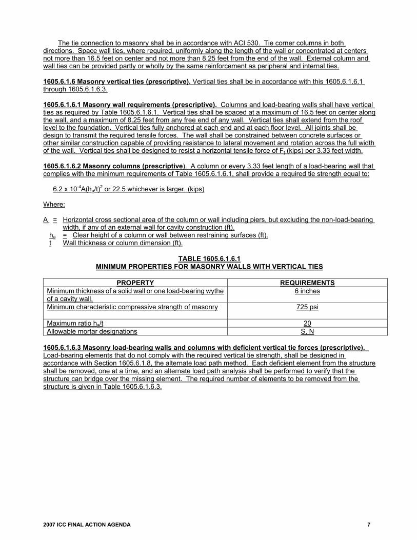
The tie connection to masonry shall be in accordance with ACI 530. Tie corner columns in both directions. Space wall ties, where required, uniformly along the length of the wall or concentrated at centers not more than 16.5 feet on center and not more than 8.25 feet from the end of the wall. External column and wall ties can be provided partly or wholly by the same reinforcement as peripheral and internal ties. 1605.6.1.6 Masonry vertical ties (prescriptive). Vertical ties shall be in accordance with this 1605.6.1.6.1 through 1605.6.1.6.3. 1605.6.1.6.1 Masonry wall requirements (prescriptive). Columns and load-bearing walls shall have vertical ties as required by Table 1605.6.1.6.1. Vertical ties shall be spaced at a maximum of 16.5 feet on center along the wall, and a maximum of 8.25 feet from any free end of any wall. Vertical ties shall extend from the roof level to the foundation. Vertical ties fully anchored at each end and at each floor level. All joints shall be design to transmit the required tensile forces. The wall shall be constrained between concrete surfaces or other similar construction capable of providing resistance to lateral movement and rotation across the full width of the wall. Vertical ties shall be designed to resist a horizontal tensile force of Ft (kips) per 3.33 feet width. 1605.6.1.6.2 Masonry columns (prescriptive). A column or every 3.33 feet length of a load-bearing wall that complies with the minimum requirements of Table 1605.6.1.6.1, shall provide a required tie strength equal to: 6.2 x 10⁻⁴A(ha/t)2 or 22.5 whichever is larger. (kips) Where: A = Horizontal cross sectional area of the column or wall including piers, but excluding the non-load-bearing
width, if any of an external wall for cavity construction (ft). ha = Clear height of a column or wall between restraining surfaces (ft).
t Wall thickness or column dimension (ft).
TABLE 1605.6.1.6.1 MINIMUM PROPERTIES FOR MASONRY WALLS WITH VERTICAL TIES
PROPERTY REQUIREMENTS
Minimum thickness of a solid wall or one load-bearing wythe of a cavity wall.
6 inches
Minimum characteristic compressive strength of masonry 725 psi
Maximum ratio ha/t 20 Allowable mortar designations S, N
1605.6.1.6.3 Masonry load-bearing walls and columns with deficient vertical tie forces (prescriptive). Load-bearing elements that do not comply with the required vertical tie strength, shall be designed in accordance with Section 1605.6.1.8, the alternate load path method. Each deficient element from the structure shall be removed, one at a time, and an alternate load path analysis shall be performed to verify that the structure can bridge over the missing element. The required number of elements to be removed from the structure is given in Table 1605.6.1.6.3.

8 2007 ICC FINAL ACTION AGENDA
TABLE 1605.6.1.6.3 REMOVAL OF DEFICIENT MASONRY VERTICAL TIE ELEMENTS
VERTICAL LOAD-BEARING
ELEMENT TYPE
DEFINITION OF ELEMENT EXTENT OF STRUCTURE
TO REMOVE IF DEFICIENT Column Primary structural support
member acting alone Clear height between lateral restraints
Wall Incorporating One or More Lateral Supportsa
All external and internal load-bearing walls
Length between lateral supports or length between a lateral support and the end of the wall. Remove clear height between lateral restraints.
Wall Without Lateral Supports All external and internal load-bearing walls
For internal walls: length not exceeding 2.25H, anywhere along the wall where H is the clear height of the wall. For external walls: Full length. For both wall types: clear height between lateral restraints.
a. Lateral supports shall be provided by the following: 1. An intersecting or return wall tied to a wall to which it affords support, with connections capable of
resisting a force of Ft in 0.45Ft in kips per foot height of wall, having a length without openings of net less than H/2 at right angles to the supported wall and having an average weight of not less than 70 psf.
2. A pier or stiffened section of the wall not exceeding 3.33 feet in length, capable of resisting a horizontal force of 0.45Ft in kips per foot height of wall.
3. A substantial partition at right angles to the wall having average weight of not less than 31 psf, tied with connections capable of resisting a force of 0.15Ft in kips per foot height of wall, and having a length without openings of not less than H at right angles to the supported wall.
1605.6.1.7 Masonry detailed connections for tie forces (prescriptive). Reinforced masonry connections and joints shall be ductile. Unreinforced masonry connections and joints shall have continuous reinforcement to ensure ductile behavior. 1605.6.1.8 Masonry alternate load path method design requirements (prescriptive). Alternate load path method is used to verify that the structure can bridge over removed elements. The design strengths shall be determined from ACI 530. If the design strengths are less than those in Table 1605.6.1.8, then compliance shall be in accordance with the alternate load path Section 1605.6.1.8.3.
TABLE 1605.6.1.8
ACCEPTABILITY CRITERIA AND SUBSEQUENT ACTION FOR MASONRY
STRUCTURAL BEHAVIOR ACCEPTABILITY CRITERIA SUBSEQUENT ACTION FOR ALTERNATE METHOD MODEL
Element Flexure ϕMna Section 1605.6.1.8.1
Element Axial ϕPna Section 1605.6.1.8.2
Element Shear ϕVnA Section 1605.6.1.8.3 Connections Connection Design Strengtha Section 1605.6.1.8.4 Deformation
Deformation Limits, defined in Table 1605.6.1.8.1.8
Section 1605.6.1.8.5
a. Nominal strengths are calculated with the appropriate material properties and over-strength factor Ω; all ϕ factors are defined per Chapter 3 of ACI 530.

2007 ICC FINAL ACTION AGENDA 9
1605.6.1.8.1 Masonry flexural resistance of masonry (prescriptive). The flexural design strength shall be equal to the nominal flexural strength multiplied by the strength reduction factor ϕ. The nominal flexural strength shall be determined in accordance with ACI 530. 1605.6.1.8.2 Masonry linear static analysis (prescriptive). An effective plastic hinge shall be added to the model by inserting a discrete hinge into the member at an offset from the member end if the required moment exceeds the flexural design strength and if the reinforcement layout is sufficient for a plastic hinge to form and undergo significant rotation. The location of the hinge is determined through engineering analysis. 1605.6.1.8.3 Masonry non-linear static analysis (prescriptive). Non-linear static analysis shall be modeled to represent post-peak flexural behavior. Flexural design strength must develop before shear failure occurs. 1605.6.1.8.4 Flexural design strength (prescriptive). The structural element shall be removed when the required moment exceeds the flexural design strength and shall redistributed in accordance with Section 1605.6.1.8.1.9, if the structural element is not able to develop a constant moment while undergoing continued deformation. 1605.6.1.8.5 Masonry axial resistance of masonry (prescriptive). The axial design strength with the applicable strength reduction factor ϕ shall be determined in accordance with Chapter 3 of ACI 530. If the connection exceeds the design strengths of Table 1605.6.1.8, remove the connection from the model. If the connections at each end of an element fail, remove the element and redistribute the loads in accordance with Section 1605.6.1.8.1.9. 1605.6.1.8.6 Masonry shear resistance of masonry. The shear design strength of the cross-section with the applicable strength reduction factor ϕ is determined in accordance with ACI 530. If the connection exceeds the design strengths of Table 1605.6.1.8, remove the connection from the model. If the connections at each end of an element fail, remove the element and redistribute the loads in accordance with Section 1605.6.1.8.1.9. 1605.6.1.8.7 Masonry connections (prescriptive). The connections design strength with the applicable strength reduction factor ϕ is determined in accordance with ACI 530. If the connection exceeds the design strengths of Table 1605.6.1.8, remove the connection from the model. If the connections at each end of an element fail, remove the element and redistribute the loads in accordance with Section 1605.6.1.8.1.9. 1605.6.1.8.8 Masonry deformation limits for masonry (prescriptive). Deformation limits shall be applied to structural members in accordance with Table 1605.6.1.8.1.8.
TABLE 1605.6.1.8.1.8 DEFORMATION LIMITS FOR MASONRY
CLASS 2 AND 3 BUILDINGS CLASS 4 BUILDINGS Component Ductility
υ
Rotation, Degrees θ
Ductility υ
Rotation, Degrees θ
Unreinforced Masonrya
- 2 - 1
Reinforced Masonryb
- 7 - 2
a. Response of unreinforced masonry walls is also limited by D/t, the maximum member displacement to thickness ratio. This ratio is limited to 0.75. Compare this limit, with the rotation limits and use the most restrictive condition.
b. The ultimate resistance is based on the moment capacity using 90% of Fy for reinforcement. 1605.6.1.8.9 Masonry loads associated with failed elements (prescriptive). Nonlinear Dynamic, and Linear or Nonlinear Static Analysis shall be in accordance with Section 1605.6.1.8.1.9.1 through 1605.6.1.8.1.9.3. 1605.6.1.8.9.1 Masonry nonlinear dynamic (prescriptive). For a Nonlinear Dynamic analysis, double the loads from the failed element to account for impact and apply them instantaneously to the section of the structure directly below the failed element, before the analysis continues. Apply the loads from the area supported by the failed element to an area equal to or smaller than the area from which they originated.

10 2007 ICC FINAL ACTION AGENDA
1605.6.1.8.9.2 Masonry linear or nonlinear static analysis (prescriptive). For a Linear or Nonlinear Static analysis, if the loads on the failed element are already doubled, as shown in Section 1605.6.1.8.9.3, then the loads from the failed element are applied to the section of the structure directly below the failed element before the analysis is re-run or continued. If the loads on the failed element are not doubled, then double them and apply them to the section of the structure directly below the failed element, before the analysis is re-run or continued. In both cases, apply the loads from the area supported by the failed element to an area equal to and smaller than the area from which they originated. 1605.6.1.8.9.3 Masonry linear and nonlinear static analysis load case (prescriptive). Linear and nonlinear static analysis shall have a factored load combination applied to the immediate adjacent bays and at all the floors above the removed element, using the following formula. 2.0[(0.9 or 1.2)D + (0.5L or 0.2S)] + 0.2W Where:
D = Dead load (psf) L = Live load (psf) S = Snow load (psf) W = Wind load (psf)
The adjacent bay for load-bearing wall systems shall be defined as the plan area that spans between the
removed wall and the nearest load-bearing wall. 1605.6.1.8.10 Masonry loading (prescriptive). Perimeter ground floor columns and load-bearing walls shall be designed so that the lateral uniform load, which defines the shear capacity, is greater than the load associated with the flexural capacity. 1605.6.2 Structural use of steel (prescriptive). Design against disproportionate collapse for structural steel shall be in accordance with Sections 1605.6.2.1 through 1605.6.2.4. 1605.6.2.1 Steel general (prescriptive). For composite construction, such as concrete deck slabs on steel beams, sheet steel decking with an integral slab, and columns reinforced with structural steel shapes, the application of both the requirements of this section and those provided for reinforced concrete in ACI 318 are required. For a concrete deck slab on steel beam in which the slab is used to provide internal tie capacity, the floor system and roof system shall comply with the internal tie requirements of ACI 318, while the steel frame shall comply with the other tie requirements (vertical, peripheral, and external column) and the alternate load path requirements of this section. 1605.6.2.2 Steel material properties (prescriptive). The over-strength factor specified in Table 1605.6.2.2 shall be applied to calculations of the design strength for both tie forces and alternate load path method.
TABLE 1605.6.2.2 OVER-STRENGTH FACTORS FOR STRUCTURAL STEEL
STRUCTURAL STEEL ULTIMATE OVER-STRENGTH
FACTOR, Ωu YIELD OVER-STRENGTH
FACTOR, Ωv Hot-Rolled Structural Shapes and Bars 1.05 ASTM A36/A36M 1.05 1.5 ASTM A573/A572M Grade 42 1.05 1.3 ASTM A992/A992M 1.05 1.1 All grades 1.05 1.1 Hollow Structural Sections 1.05 ASTM A500, A501, A618, and A847 1.05 1.3 Steel Pipes 1.05 ASTM A53/A53M 1.05 1.4 Plates 1.05 1.1 All other products 1.05 1.1

2007 ICC FINAL ACTION AGENDA 11
1605.6.2.3 Steel tie force requirements (prescriptive). All buildings shall be effectively tied together at each principal floor level. Each column shall be effectively held in position by means of horizontal ties in two directions, approximately at right angles, at each principal floor level supported by that column. Horizontal ties shall similarly be provided at the roof level, except where the steelwork only supports cladding that weighs not more than 14.6 psf and that carries only imposed roof loads and wind loads. Ties shall be effectively straight. Arrange continuous lines of ties as close as practical to the edges of the floor or roof and to each column line. At re-entrant corners, anchor the tie members nearest to the edge into the steel framework.
1605.6.2.3.1 Steel strength reduction factor Φ for steel tie forces (prescriptive). For the steel members and connections that provide the design tie strengths, use the applicable tensile strength reduction factors Φ from AISC 360.
1605.6.2.3.2 Steel horizontal steel ties (prescriptive). The horizontal ties may be either steel members, including those also used for other purposes, or steel reinforcement that is anchored to the steel frame and embedded in concrete, designed in accordance with ACI 318 and meeting the continuity and anchorage requirements of Section 1605.6.2.3.2.1.
1605.6.2.3.2.1 Steel continuity and anchorage of ties (prescriptive). Ties shall comply with Section 1605.6.2.3.2.1.1 through 1605.6.2.3.2.1.2. 1605.6.2.3.2.1.1 Splices (prescriptive). Splices in longitudinal steel reinforcement used to provide the design tie strength shall be lapped, welded or mechanically joined with Type 1 or Type 2 mechanical splices, in accordance with ACI 318. Locate splices away from joints or regions of high stress and shall be staggered. 1605.6.2.3.2.1.2 Hooks (prescriptive). Use seismic hooks, as defined in Chapter 21 of ACI 318, and seismic development lengths, as specified in Section 21.5.4 of ACI 318, to anchor ties to other ties. At re-entrant corners or at substantial changes in construction, ties shall be adequately developed.
1605.6.2.3.3 Steel internal ties (prescriptive). Design steel members acting as internal ties and their end connections shall be capable of resisting the following required tie strength, which need not be considered as additive to other loads. The required tie strength is calculated as follows: 0.5(1.2D + 1.6L)stLl but not less than 16.9 kips Where:
D = Dead load (psf) L = Live load (psf) Ll = Span (ft.) st = Mean transverse spacing of the ties adjacent to the ties being checked (ft.)
1605.6.2.3.4 Steel peripheral ties (prescriptive). Peripheral ties shall be capable of resisting the following load: 0.25(1.2D + 1.6L)stLl but not less than 8.4 kips Where:
D = Dead load (psf) L = Live load (psf) Ll = Span (ft.) St = Mean transverse spacing of the ties adjacent to the ties being checked (ft.)
1605.6.2.3.5 Steel tying of external columns (prescriptive). The required tie strength for horizontal ties anchoring the column nearest to the edges of a floor or roof and acting perpendicular to the edge is equal to the greater of the load calculated in Section 1605.6.2.3.3 or 1% of the maximum factored vertical dead and live load in the column that is being tied, considering all load combinations used in the design.

12 2007 ICC FINAL ACTION AGENDA
1605.6.2.3.6 Steel vertical ties (prescriptive). All columns shall be continuous through each beam-to-column connection. All column splices shall provide a design tie strength equal to the largest factored vertical dead and live load reaction (from all load combinations used in the design) applied to the column at any single floor level located between that column splice and the next column splice down or the base of the column.
1605.6.2.3.7 Steel columns with deficient vertical tie forces (prescriptive). The alternate load path method shall be used in each deficient column, where it is not possible to provide the vertical required tie strength. Remove each deficient column from the structure, one at a time, and perform an alternate load path analysis to verify that the structure can bridge over the missing column. 1605.6.2.4 Steel alternate load path method design requirements (prescriptive). Alternate load path method is used to verify that the structure can bridge over removed elements. The design strengths shall be determined in accordance with AISC 360. If the design strengths are less than those in Table 1605.6.2.4.1, then compliance shall be in accordance with the alternate load path model Sections 1605.6.2.4.1 through 1605.6.2.4.5.
TABLE 1605.6.2.4.1 ACCEPTABILITY CRITERIA AND SUBSEQUENT ACTION FOR STRUCTURAL STEEL
STRUCTURAL BEHAVIOR
ACCEPTABILITY CRITERIA SUBSEQUENT ACTION FOR VIOLATION
OF CRITERIA Element Flexure ϕMn
a Section 1605.6.2.4.1 Element Combined Axial and Bending
AISC LRFD Chapter H Interaction Equationsa
Section 1605.6.2.4.2
Element Shear ϕVna Section 1605.6.2.4.3
Connections Connection Design Strengtha Section 1605.6.2.4.4 Deformation Deformation Limits, defined in
Table 1605.6.2.5(1) Section 1605.6.2.4.5
a. Nominal strengths are calculated with the appropriate material properties and over-strength factors Ωy and
Ωu depending upon the limit state; all Φ factors are defined per AISC 360.
1605.6.2.4.1 Steel flexural resistance of structural steel (prescriptive). A flexural member can fail by reaching its full plastic moment capacity, or it can fail by lateral-torsional buckling (LTB), flange local buckling (FLB), or web local buckling (WLB). Calculate nominal moment strength, M
n, in accordance with AISC 360. If a
flexural member's capacity is governed by a buckling mode of failure, remove the element when the internal moment reaches the nominal moment strength. Distribute the loads associated with the element in accordance with Section 1605.6.2.4.1.1. If the member strength is not governed by buckling, the strength will be governed by plastification of the cross-section and it may be possible for a plastic hinge to form.
Deformation of primary members shall not cause premature failure in secondary members, due to geometric interference. Torsional rotation of a girder shall not cause excessive deformation and stresses in any beam that frames into the girder with a simple shear tab connection. 1605.6.2.4.1.1 Steel formation of plastic hinge (prescriptive). If hinge formation, i.e. material non-linearity, is included in the alternate load path analysis, the requirements of Section A5.1 of the AISC 360 for plastic design shall be met. AISC 360 permits plastic analysis only when the structure can remain stable, both locally and globally, up to the point of plastic collapse or stabilization. Where the analysis indicates the formation of multiple plastic hinges, ensure each cross-section or connection that is assumed to form a plastic hinge is capable of not only forming the hinge, but is also capable of the deformation demands created by rotation of the hinge as additional hinges are formed in the element or structure. Since the element could be required to undergo large deformations as plastic hinges are being formed, special lateral bracing is required. The magnitude of the plastic moment, M
p, used for analysis shall consider the influence of axial or shear force
when appropriate. Further information on plastic design is provided in The Plastic Methods of Structural Analysis (Neal 1963) and Plastic Design of Steel Frames (Beedle 1958).
1605.6.2.4.1.2 Steel modeling of a plastic hinge (prescriptive). Plastic hinges shall be modeled in accordance with Sections 1605.6.2.4.1.2.1 through 1605.6.2.4.1.2.2.

2007 ICC FINAL ACTION AGENDA 13
1605.6.2.4.1.2.1 Steel linear static analysis (prescriptive). For Linear Static analyses, when the calculated moment exceeds the nominal moment strength and it is determined that the element is capable of forming a plastic hinge, insert an "equivalent" plastic hinge into the model by inserting a discrete hinge in the member at an offset from the member end and add two constant moments, one at each side of the new hinge, in the appropriate direction for the acting moment. The magnitude of the constant moments is equal to the determined plastic moment capacity of the element. Determine the location of the plastic hinge through engineering analysis and judgment or with the guidance provided for seismic connections in FEMA 350, Recommended Seismic Design Criteria for New Steel Moment-Frame Buildings and AISC 341, Seismic Provisions for Structural Steel Buildings. 1605.6.2.4.1.2.2 Steel nonlinear static and dynamic analysis (prescriptive). For Nonlinear Static and Dynamic Analysis, use software capable of representing post-peak flexural behavior and considering interaction effects of axial loads and moment. Ensure that shear failure will not occur prior to developing the full flexural design strength.
1605.6.2.4.2 Steel combined axial and bending resistance of structural steel (prescriptive). The response of an element under combined axial force and bending moment can be force controlled (i.e. non-ductile) or deformation controlled (i.e. ductile). The response is determined by the magnitude of the axial force, cross sectional properties, magnitude/direction of moments, and the slenderness of the element. If the element is sufficiently braced to prevent buckling and the ratio of applied axial force to the axial force at yield (P
u/P
y where P
y = A
gF
y) is less than 0.15, the member can be treated as deformation controlled with no reduction in
plastic moment capacity, i.e. as a flexural member in accordance with Section 1605.6.2.4.1. For all other cases, treat the element as a beam-column and make the determination of whether the element is deformation or force controlled in accordance with the provisions of FEMA 356 Chapter 5.
1. When the controlling action for the element is force controlled, evaluate the strength of the element using the interaction equations in Chapter H of AISC 360, incorporating the appropriate strength reduction factors Φ and the over-strength factor Ω. Remove the element from the model when the acceptability criteria is violated and redistribute the loads associated with the element in accordance with Section 1605.6.2.4.6.
2. When the controlling action for the element is deformation controlled, the element can be modeled for inelastic action using the modeling parameters for nonlinear procedures in Table 5-6 in FEMA 356. In linear analyses, take the force deformation characteristics of the elements as bilinear (elastic – perfectly plastic), ignoring the degrading portion of the relationship specified in FEMA 356. The modeling of plastic hinges for beam-columns in linear static analyses must include a reduction in the moment capacity due to the effect of the axial force (in accordance with FEMA 356 Equation 5-4). For nonlinear analysis, the modeling of elements, panel zones, or connections must follow the guidelines in FEMA 356. Nonlinear analyses must utilize coupled (P-M-M) hinges that yield based on the interaction of axial force and bending moment. In no cases shall the deformation limits established in FEMA 356 exceed the deformation limits established in Table 1605.6.2.5(1).
1605.6.2.4.3 Shear resistance of structural steel (prescriptive). The acceptability criteria for shear of structural steel is based on the nominal shear strength of the cross-section, in accordance with AISC 360, multiplied by the strength reduction factor Φ and the over-strength factor Ω. If the element exceeds the design strengths of Table 1605.6.2.4.1, remove the element and redistribute the loads associated with the element in accordance with Section 1605.6.2.4.6.
1605.6.2.4.4 Steel connections (prescriptive). All connections shall meet the requirements of AISC 360; employ the applicable strength reduction factor Φ for each limit state and over-strength factor Ω. If a connection exceeds the design strengths of Table 1605.6.2.4.1, remove it from the model. If the connections at each end of an element fail, remove the element and redistribute the loads associated with the element in accordance with Section 1605.6.2.4.6. 1605.6.2.4.5 Deformation limits for structural steel (prescriptive). The Deformation Limits are given in Table 1605.6.2.5(1). Fully Restrained and Partially Restrained connections are given in Table 1605.6.2.5(2). Verify and quantify the rotational capacities of connections that are not listed in Table 1605.6.2.5(2) in accordance with the testing requirements of Appendix S of AISC 341. 1605.6.2.4.6 Steel loads associated with failed elements (prescriptive). Nonlinear Dynamic, and Linear or Nonlinear Static Analysis shall be in accordance with Section 1605.6.2.4.6.1through 1605.6.2.4.6.2.

14 2007 ICC FINAL ACTION AGENDA
1605.6.2.4.6.1 Steel nonlinear dynamic (prescriptive). For a Nonlinear Dynamic analysis, double the loads from the failed element to account for impact and apply them instantaneously to the section of the structure directly below the failed element, before the analysis continues. Apply the loads from the area supported by the failed element to an area equal to or smaller than the area from which they originated. 1605.6.2.4.6.2 Steel linear or nonlinear static analysis (prescriptive). For a Linear or Nonlinear Static analysis, if the loads on the failed element are already doubled as shown in Section 1605.6.2.4.6.3, then the loads from the failed element are applied to the section of the structure directly below the failed element before the analysis is re-run or continued. If the loads on the failed element are not doubled, then double them and apply them to the section of the structure directly below the failed element, before the analysis is re-run or continued. In both cases, apply the loads from the area supported by the failed element to an area equal to or smaller than the area from which they originated. 1605.6.2.4.6.3 Steel linear and nonlinear static analysis load case (prescriptive). Linear and nonlinear static analysis shall have a factored load combination applied to the immediate adjacent bays and at all the floors above the removed element, using the following formula. 2.0[(0.9 or 1.2)D + (0.5L or 0.2S)] + 0.2W Where:
D = Dead load (psf) L = Live load (psf) S = Snow load (psf) W = Wind load (psf)
TABLE 1605.6.2.5(1) DEFORMATION LIMITS FOR STRUCTURAL STEEL
CLASS 2 AND 3 BUILDINGS CLASS 4 BUILDINGS
Component Ductility μ
Rotation, Degrees
θ
Ductility μ
Rotation, Degrees
θ Beams – Seismic Sectiona 20 12 10 6 Beams – Compact Sectiona 5 3 Beams – Non-Compact Sectiona 1.2 1 Plates 40 12 20 6 Columns and Beam-Columns 3 2 Steel Frame Connections; Fully Restrained
Welded Beam Flange or Coverplated (all types) 2.0 1.5
Reduced Beam Section 2.6 2 Steel Frame Connections; Partially Restrained
Limit State governed by rivet shear or flexural yielding of plate, angle or T-section
2.0 1.5
Limit State governed by high strength bolt shear, tension failure of rivet or bolt, or tension failure of plate, angle or T-section
1.3 0.9
a. As defined in AISC 341.

2007 ICC FINAL ACTION AGENDA 15
TABLE 1605.6.2.5(2) STEEL MOMENT FRAME CONNECTION TYPES
CONNECTION DESCRIPTION TYPE
Strong Axis Welded Unreinforced Flange Full penetration welds between beams and columns,
flanges, bolted or welded web. FR
Welded Flange Plates Flange plate with full-penetration weld at column and fillet welded to beam flange.
FR
Welded Cover-Plated Flanges Beam flange and cover-plate are welded to column flange. FR Bolted Flanges Plates Flange plate with full-penetration weld at column and field
bolted to beam flange. FR or PR
Improved Welded Unreinforced Flange – Bolted Web
Full-penetration welds between beam and column flanges, bolted web.
FR
Improved Welded Unreinforced Flange – Welded Web
Full-penetration welds between beam and column flanges, welded web.
FR
Free Flange Web is coped at ends of beam to separate flanges; welded web tap resists shear and bending moment due to eccentricity due to coped web.
FR
Welded Top and Bottom Haunches
Haunched connection at top and bottom flanges. FR
Reduced Beam Section Connection in which net area of beam flange is reduced to force plastic hinging away from column face.
FR
Top and Bottom Clip Angles Clip angle bolted or riveted to beam flange and column flange.
PR
Double Split Tee Split tees bolted or riveted to beam flange and column flange.
PR
Composite Top and Clip Angle Bottom
Clip angle bolted or riveted to column flange and beam bottom flange with composite slab.
PR
Bolted Flange Plates Flange plate with full-penetration weld at column and bolted to beam flange.
PR
Bolted End Plates Stiffened or unstiffened end plate welded to beam and bolted to column flange.
PR
Shear Connection with or without Slab
Simple connection with shear tab, may have composite slab. PR
Weak Axis Fully Restrained Full-penetration welds between beams and columns,
flanges, bolted or welded web. FR
Shear Connection Simple connection with shear tab. PR Note: PR = Partially Restrained Connections FR = Fully Restrained Connections 1605.6.3 Structural use of plain, reinforced and prestressed concrete (prescriptive). Design against disproportionate collapse for concrete shall be in accordance with ACI 318 or 1605.6.3.1. For a reinforced concrete wall, the distance between lateral supports that are subject to a maximum length shall not exceed 2.25 times the height of the wall. For composite construction, such as concrete deck slabs on steel beams, sheet steel decking with an integral slab, and columns reinforced with structural steel shapes, the application of both the requirements of this section and those provided for structural steel in Section 1605.6.2 are required. For a concrete deck slab on steel beam in which the slab is used to provide internal tie capacity, the floor system and roof system shall comply the internal tie requirements of ACI 318, while the steel frame shall comply the other tie requirements (vertical, peripheral, and external column). 1605.6.3.1 Concrete alternate load path method design requirements (prescriptive). Alternate load path method is used to verify that the structure can bridge over removed elements. The design strengths shall be determined in accordance with ACI 318. If the design strengths are less than those in Table 1605.6.3.1, then compliance shall be in accordance with the alternate load path model subsection.

16 2007 ICC FINAL ACTION AGENDA
TABLE 1605.6.3.1 ACCEPTABILITY CRITERIA AND SUBSEQUENT ACTION FOR REINFORCED CONCRETE
STRUCTURAL
BEHAVIOR
ACCEPTABILITY CRITERIA SUBSEQUENT ACTION
FOR VIOLATION OF CRITERIA Element Flexure ϕMn
a Section 1605.6.3.1.2 Element Combined Axial and Bending
ACI 318 Chapter 10 Provisionsa
Section 1605.6.3.1.3
Element Shear ϕVna Section 1605.6.3.1.4
Connections Connection Design Strengtha Section 1605.6.3.1.5 Deformation Deformation Limits, defined in
Table 1605.6.3.1.6 Section 1605.6.3.1.6
Nominal strengths are calculated with the appropriate material properties and over-strength factors Ωy and
Ωu depending upon the limit state; all Φ factors are defined in accordance with ACI 318.
1605.6.3.1.1 Over-strength factors for reinforced concrete (prescriptive). The applicable over-strength factor shall be applied to calculations of the design strength alternate load path method. The over-strength factors are given in Table 1605.6.3.1.1.
TABLE 1605.6.3.1.1 OVER-STRENGTH FACTORS FOR REINFORCED CONCRETE
REINFORCED CONCRETE OVER-STRENGTH FACTOR, Ω
Concrete Compressive Strength 1.25 Reinforcing Steel (ultimate and yield strength) 1.25 1605.6.3.1.2 Flexural resistance of reinforced concrete (prescriptive). The flexural design strength shall be equal to the nominal flexural strength calculated with the appropriate material properties and over-strength factor Ω, multiplied by the strength reduction factor ϕ of 0.75. The nominal flexural strength shall be calculated in accordance with ACI 318. 1605.6.3.1.2.1 Concrete linear static analysis (prescriptive). For linear static analysis when the required moment exceeds the flexural design strength and when the reinforcement layout is sufficient for a plastic hinge to form and undergo significant rotation, an equivalent plastic hinge shall be added to the model by inserting a discrete hinge at the correct location within the member. The location of the hinge shall be determined through engineering analysis, but shall be less than ½ the depth of the member from the face of the column. Apply two constant moments, one at each side of the new hinge, in the appropriate direction of the acting moment. 1605.6.3.1.2.2 Concrete non-linear static and dynamic analysis (prescriptive). For non-linear static and dynamic analysis shall be model to represent post-peak flexural behavior. Flexural design strength must develop before shear failure occurs. 1605.6.3.1.2.3 Flexural design strength (prescriptive). The structural element shall be removed when the required moment exceeds the flexural design strength and shall be redistributed in accordance with Section 1605.6.3.2, when the structural element is not able to develop a constant moment while undergoing continued deformation. 1605.6.3.1.3 Combined axial and bending resistance of reinforced concrete (prescriptive). The acceptability criteria for elements undergoing combined axial and bending loads are based on the provisions given in Chapter 10 of ACI 318, including the appropriate strength reduction factor Φ and the over-strength factor Ω. If the combination of axial load and flexure in an element exceeds the design strength and the un-factored axial load is greater than the nominal axial load strength at balanced strain P
b, remove the element
and redistribute the loads associated with the element in accordance with Section 1605.6.3.2. If the un-factored axial load is less than P
b, then insert an equivalent plastic hinge into the column, in accordance with
the procedure in Section 1605.6.3.1.2. 1605.6.3.1.4 Shear resistance of reinforced concrete (prescriptive). The acceptability criteria for shear are based on the shear design strength of the cross-section, in accordance with ACI 318, using the appropriate strength reduction factor Φ and the over-strength factor Ω. When the element violates the shear criteria, remove the element and redistribute the loads associated with the element in accordance with Section 1605.6.3.2.

2007 ICC FINAL ACTION AGENDA 17
1605.6.3.1.5 Concrete connections (prescriptive). The connections design strength with the applicable strength reduction factor ϕ shall be determined in accordance with ACI 318. The effects of embedment length, reinforcement continuity, and confinement of reinforcement in the joint shall be considered when determining the joint design strength. When the connection exceeds the design strengths of Table 1605.6.3.1, remove it from the model. When the connections at each end of an element fail, remove the element and redistribute the loads associated with the element in accordance with Section 1605.6.3.2. 1605.6.3.1.6 Deformation limits for reinforced concrete (prescriptive). When the element or the connections at each end of an element exceed the a deformation limit in Table 1605.6.3.1.6, remove the element and redistribute the loads associated with the element in accordance with Section 1605.6.3.2. Deformation limits are applied only to the structural elements, not to the connections.
TABLE 1605.6.3.1.6 DEFORMATION LIMITS FOR REINFORCED CONCRETE
CLASS 2 & 3 BUILDINGS CLASS 4 BUILDINGS
Component Ductility
υ
Rotation, Degrees
θ
Ductility υ
Rotation, Degrees
θ Slab and Beam Without Tension Membramea Single-Reinforced or Double-Reinforced without
Shear Reinforcingb- 3 - 2
Double-Reinforced with Shear Reinforcingc - 6 - 4 Slab and Beam with Tension Membramea
Normal Proportions (L/h ≥ 5) - 20 - 12 Deep Proportions (L/h < 5) - 12 - 8
Compression Members Walls and Seismic Columnsd,e 3 - 2 -
Non-Seismic Columnse 1 - 0.9 - a. The tension membrane effect is an extension of the yield line theory of slabs and it increases the ultimate
resistance. It cannot be developed when the slab has a free edge. b. Single-reinforced members have flexural bars in one face or mid-depth only. Double-reinforced members
have flexural reinforcing in both faces. c. Stirrups or ties meeting ACI 318 minimums must enclose the flexural bars in both faces, otherwise use the
response limits for Double-Reinforced without shear reinforcing. d. Seismic columns have ties or spirals in accordance with ACI 318 Chapter 21 seismic design provisions for
special moment frames. e. Ductility of compression members is the ratio of total axial shortening to axial shortening at the elastic limit. 1605.6.3.2 Concrete loads associated with failed elements (prescriptive). The following procedure shall be met for Nonlinear Dynamic, and Linear or Nonlinear Static Analysis. 1605.6.3.2.1 Concrete nonlinear dynamic (prescriptive). For a Nonlinear Dynamic analysis, double the loads from the failed element to account for impact and apply them instantaneously to the section of the structure directly below the failed element, before the analysis continues. Apply the loads from the area supported by the failed element to an area equal to or smaller than the area from which they originated. 1605.6.3.2.2 Concrete linear or nonlinear static analysis (prescriptive). For a Linear or Nonlinear Static analysis, when the loads on the failed element are already doubled as shown in Section 1605.6.2.4.7.3, then the loads from the failed element are applied to the section of the structure directly below the failed element, before the analysis is re-run or continued. When the loads on the failed element are not doubled, then double them and apply them to the section of the structure directly below the failed element, before the analysis is re-run or continued. In both cases, apply the loads from the area supported by the failed element to an area equal to and smaller than the area from which they originated. 1605.6.3.2.3 Concrete linear and nonlinear static analysis load case (prescriptive). Linear and nonlinear static analysis shall have a factored load combination applied to the immediate adjacent bays and at all the floors above the removed element, using the following formula.

18 2007 ICC FINAL ACTION AGENDA
2.0[(0.9 or 1.2)D + (0.5L or 0.2S)] + 0.2W Where:
D = Dead load (psf) L = Live load (psf) S = Snow load (psf) W = Wind load (psf)
1605.6.4 Key elements analysis (prescriptive). When applying the alternate load path method design requirements from Sections 1605.6.1.8, 1605.6.2.4 or 1605.6.3.1 and the removal of columns and lengths of walls result in a disproportionate collapse, then such element shall be designed to withstand an accidental design loading of 700 psf applied in the horizontal and vertical directions (in one direction at a time) to the member and any attached components. 1605.6.4.1 Load combinations (prescriptive). The following load combinations shall be used in addition to the accidental design loading in the key element analysis: 1.2D + Ak + (0.5L or 0.2S) (0.9 or 1.2)D + Ak + 0.2W As per the definition of key element, Ak = 700 psf. Reason: This code change proposal is one of fourteen proposals being submitted by the International Code Council Ad Hoc Committee on Terrorism Resistant Buildings. The purpose of this proposal is to increase the robustness of building structural systems to guard against the possibility of collapse, property loss, and casualties that are disproportionate to the original damaging event. Such a scenario is often called progressive collapse. Incredible as it may seem, our codes and standards do not, in any way prohibit a structural system that is, literally, the proverbial “house of cards”.
This proposal is intended to implement the very first recommendation of the National Institute of Standards and Technology’s (NIST) report on the World Trade Center (WTC) tragedy. It is very important to understand that neither the NIST Report nor the proponents of this change seek to make buildings immune to attack by airliners. Rather, the WTC event resulted in a detailed examination of the adequacy of our codes in connection with a wide variety of much less dramatic damage scenarios, including now, for the first time, some that might be willful and deliberate. The Code and the many standards that it references deal comprehensively and thoroughly with the live and dead loads that buildings routinely encounter, including exceptional but predictable extreme loads such as wind and seismic. The Code does not deal at all with damage, accidental or deliberate. The possibility of deliberate damage was brought home by the WTC tragedy but it has always existed. The same is true with accidental damage. Whether a bomb, a gas explosion, or a vehicle accidentally taking out a ground level column, it is simply unacceptable that the current code would permit structural systems that are prone to total progressive collapse following a relatively minor initiating event.
This is the sort of issue that one might expect to be addressed through engineering design standards such as ASCE-7 and others. It is not and there is not, at this writing, any firm plan or timetable to do so. It is the proponents’ belief that the time is long past for such a dramatic gap in the public safety requirement for buildings to exist. The proponents believe that the Code should establish a strong public policy against disproportionate damage and progressive collapse. This proposal also includes detailed technical requirements. Those would be better included as standards that could be referenced. The near complete absence of detailed technical design requirements from American standards means that they have to be included here. Only ACI 318-02 contains any technical requirements, and those are only applicable to the “tie forces” approach in concrete design. That standard is referenced by this proposal and detailed technical requirements for that subject are not included in the proposal. It is the proponents’ hope that the nation’s engineering community will take up, soon and with urgency, the challenge of preparing detailed technical standards that will be suitable for reference in future editions of the Code.
The need for such standards has been debated for years in the technical community. That debate has resulted in little but inaction. While the American debate droned on, the rest of the English speaking world, indeed much of the rest of the world, has adopted effective provisions to guard against progressive collapse. Key federal agencies, such as the General Services Administration and the Department of Defense, have prepared and adopted workable and effective provisions for their buildings. The International Building Code remains silent on the issue. The time for silence has long since passed. The proponents believe that the Code Officials who are the International Codes Council, and who are those upon whom the American public relies for their safety in buildings, need to take the lead on this very important issue. The approach to preventing disproportionate damage and progressive collapse taken by this proposal is not new. It is based upon provisions that have been a part of British Codes for a generation. The approach has been adopted by most of the nations of the Commonwealth and are incorporated within the Eurocodes. Over the last thirty (30) years they have proven to be workable, readily applied, and have little impact on hard construction cost. They do require additional engineering analysis and careful detailing of connections. They are not unlike the seismic provisions of the code in that respect.
The proposal provides for two approaches to design for limiting disproportionate damage. The first, incorporated in proposed Section 1605.4, sets forth criteria for a performance design approach to be carried out in accordance with accepted engineering practice. The second, incorporated in proposed Section 1605.5, lays out a prescription “deemed to comply” approach. Either is acceptable to demonstrate compliance. The provisions of proposed Section 1605.4 are largely based on the methods prescribed by the General Services Administration and the Department of Defense’s Uniform Facilities Criteria that have been in use for a number of years, but also references relevant provisions of ACI 318-02. 1604.11 – establishes the basic requirement that structures be designed to resist disproportionate collapse.

2007 ICC FINAL ACTION AGENDA 19
1605.1 – sets forth the basic standard that the Code will require be met 1605.2 – provides definitions needed to understand and apply the Sections. 1605.3 – establishes a four level classification system for all buildings by size and by occupancy group.
It is generally true that, in the Code, requirements vary by risk. Risk includes both the probability of an issue and the scale of its consequences. The higher the risk (either probability or consequences) the higher the code requirements that can be justified. It is well settled in the Code that risk varies by occupancy group and by size. Numerous Code provisions are differentiated along those lines. So it is with disproportionate collapse. The four classifications provided are not arbitrary nor do they rely upon “seat of the pants” judgment. They reflect the classifications found in the British Codes. Those classifications were established through a very detailed and scientific risk analysis. The analysis is an available public document and is listed in the bibliography. 1605.4 – sets forth the criteria for the performance design approach. Different requirements are set forth for each of the four (4) classes established by Section 1605.3 Class 1 buildings are not required to comply. Class 2 buildings are required to have effective horizontal ties.
Class 3 buildings are required to have effective horizontal and vertical ties or be analyzed in accordance with the alternate load path approach. Class 4 buildings are required to comply with the same requirements as Class 3 buildings, but they are also required to be analyzed in accordance with a peer reviewed systematic risk assessment which takes into account the hazards associated with that specific building and its specific structural system.
Specific requirements are set forth the Class 2 buildings of masonry (1605.4.2.1), steel (1605.4.2.2), and concrete (1605.4.2.3).
Similarly, the requirements for Class 3 buildings and set forth for masonry (1605.4.3.1), steel (1605.4.3.2), and concrete (1605.4.3.3). 1605.5 sets forth the prescription “deemed to comply” design approach. Like Section 1605.4, the requirements for each class of building are set forth separately, for ease of use, and within each class the approach that can be used for masonry, steel, and concrete are each set out in their own subsection. It is here that ACI 318-02 is referenced for the concrete tie force approach. Bibliography:
American Concrete Institute (ACI) Building Code Requirements for Structural Concrete (ACI 318-05) and Commentary (ACI 318R-05). American Concrete Institute: Farmington Hills, Michigan, 2005.
American Society of Civil Engineers (ASCE) 7-2005, Minimum Design Loads for Buildings and Other Structures. American Society of Civil of Engineers: Danvers, Massachusetts, 2005. General Services Administration. Facilities Standards for the Public Building Service, Chapter 8, Security Design. Washington, DC. November 2000. National Institute of Standards and Technology. Final Report of the National Construction Safety Team on the Collapses of the World Trade Center Towers. United States Government Printing Office: Washington, D.C. September 2005. United Kingdom, Office of the Deputy Prime Minister. Building Regulations, 2004 (Structure); Approved Document A. United Kingdom: London, 2004. United Kingdom, Guidance on Robustness and Provision Against Accidental Actions.” Allot and Lomax Proposal on the Current Application of Requirements A3 of the Building Regulations 1991. United Kingdom: London. United Kingdom, Proposed Revised Guidance on Meeting Compliance with the Requirements of Building Regulation, A3: Revision of Allot and Lomax Proposal. United Kingdom: London. 2000. United States Department of Defense. Unified Facilities Criteria, Design of Buildings to Resist Progressive Collapse, UFC 4-023-03. Washington, DC., January 25, 2005. Cost Impact: The proponents believe that actual construction costs will be increased little, if at all. This belief is based on 30 years of British experience. There will be increased design analysis and detailing costs, but those will be modest when viewed as a percentage of total construction costs. Committee Action: Disapproved Committee Reason: There are concerns that the application of the proposed disproportionate collapse provisions would result in unintended consequences and that these provisions are arbitrary and unenforceable. The proposal would inappropriately place material requirements in Chapter 16. It is unclear whether a minor addition would trigger compliance for the entire structure. Terms such as “abnormal hazard” and “masonry cross-wall construction” are not clear. The definition of structural frame differs from Table 601 requirements. It is unclear if this difference is intentional or an oversight. The definition of key element contains a requirement for a 700 psf accidental design loading. The correct application of this load to the structure is not apparent. There are potential conflicts in the building class for Group R-3 occupancies. Also any residential building that can’t comply with the IRC would need to comply with these provisions. It is unclear how the requirements that apply to specific types of construction would be applied to typical buildings that consist of combinations of various construction types. Assembly Action: None Individual Consideration Agenda This item is on the agenda for individual consideration because a public comment was submitted. Public Comment: William M. Connolly, State of New Jersey, Department of Community Affairs, Division of Codes and Standards, representing International Code Council Ad Hoc Committee on Terrorism Resistant Buildings, requests Approval as Modified by this public comment.
20 2007 ICC FINAL ACTION AGENDA
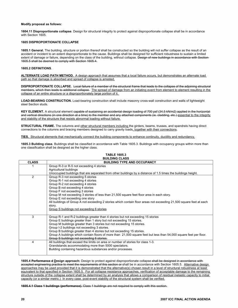
Modify proposal as follows: 1604.11 Disproportionate collapse. Design for structural integrity to protect against disproportionate collapse shall be in accordance with Section 1605. 1605 DISPROPORTIONATE COLLAPSE 1605.1 General. The building, structure or portion thereof shall be constructed so the building will not suffer collapse as the result of an accident or incident to an extent disproportionate to the cause. Buildings shall be designed for sufficient robustness to sustain a limited extent of damage or failure, depending on the class of the building, without collapse. Design of new buildings in accordance with Section 1605.5 shall be deemed to comply with Section 1605.4. 1605.2 DEFINITIONS. ALTERNATE LOAD PATH METHOD. A design approach that assumes that a local failure occurs, but demonstrates an alternate load path so that damage is absorbed and spread of collapse is arrested. DISPROPORTIONATE COLLAPSE. Local failure of a member of the structural frame that leads to the collapse of the adjoining structural members, which then leads to additional collapse. The spread of damage from an initiating event from element to element resulting in the collapse of an entire structure or a disproportionately large portion of it. LOAD-BEARING CONSTRUCTION. Load-bearing construction shall include masonry cross-wall construction and walls of lightweight steel Section studs. KEY ELEMENT. A structural element capable of sustaining an accidental design loading of 700 psf (34.5 kN/m2) applied in the horizontal and vertical directions (in one direction at a time) to the member and any attached components (ie. cladding, etc.) essential to the integrity and stability of the structure that resists abnormal loading without failure. STRUCTURAL FRAME. The columns and other structural members including the girders, beams, trusses, and spandrels having direct connections to the columns and bracing members designed to carry gravity loads, together with their connections. TIES. Structural elements that mechanically connect the building components to enhance continuity, ductility and redundancy. 1605.3 Building class. Buildings shall be classified in accordance with Table 1605.3. Buildings with occupancy groups within more than one classification shall be designed as the higher class.
TABLE 1605.3 BUILDING CLASS
CLASS BUILDING TYPE AND OCCUPANCY 1 Group R-3 or R-5 not exceeding 4 stories
Agricultural buildings Unoccupied buildings that are separated from other buildings by a distance of 1.5 times the buildings height.
2 Group R-3 not exceeding 5 stories Group R-1 not exceeding 4 stories Group R-2 not exceeding 4 stories Group B not exceeding 4 stories Group F not exceeding 3 stories Group M not exceeding 3 stories of less than 21,500 square feet floor area in each story. Group E not exceeding one story All buildings of Group A not exceeding 2 stories which contain floor areas not exceeding 21,500 square feet at each story. Group S buildings not exceeding 6 stories
3 Group R-1 and R-2 buildings greater than 4 stories but not exceeding 15 stories Group E buildings greater than 1 story but not exceeding 15 stories. Group M buildings greater than 3 stories but not exceeding 15 stories. Group I-2 buildings not exceeding 3 stories. Group B buildings greater than 4 stories but not exceeding 15 stories. Group A buildings which contain floors of more than 21,500 square feet but less than 54,000 square feet per floor. Group S buildings not exceeding 6 stories.
4 All buildings that exceed the limits on area or number of stories for class 1-3. Grandstands accommodating more than 5000 spectators. Building containing hazardous substances and/or processes.
1605.4 Performance d Design approach: Design to protect against disproportionate collapse shall be designed in accordance with accepted engineering practice to meet the requirements of this section or shall be in accordance with Section 1605.5. Alternative design approaches may be used provided that it is demonstrated that the alternative(s) chosen result in a level of structural robustness at least equivalent to that specified in Section 1605.5. For all collapse resistance approaches, verification of acceptable damage to the remaining structure outside of the collapse extent shall be determined by an analysis that allows a comparison of residual inelastic capacity to initial capacity (or a similar metric.) In every case, post-event stability of the structural system shall be verified. 1605.4.1 Class 1 buildings (performance). Class 1 buildings are not required to comply with this section.

2007 ICC FINAL ACTION AGENDA 21
1605.4.2 Class 2 buildings (performance). Class 2 buildings shall be provided with horizontal ties or with anchorage. 1605.4.2.1 Class 2 structural use of reinforced and unreinforced masonry (performance). Design to protect against disproportionate collapse for unreinforced masonry construction shall be in accordance with Section 1605.4.2.1.1 through Section 1605.4.2.1.5. 1605.4.2.1.1 Class 2 masonry general (performance). For composite construction, such as masonry load-bearing walls with other materials for the floor and roof systems, the application of both the requirements of this section and those provided for the other materials are required. Peripheral, internal, and column or wall ties shall be provided at each floor level and at roof level, except where the roof is of lightweight construction, no such ties need be provided at that level. Horizontal ties shall be provided by structural members or by reinforcement that is provided for other purposes. 1605.4.2.1.2 Class 2 masonry tie force design requirements (performance). Load-bearing walls shall be tied from the lowest to the highest level. 1605.4.2.1.3 Class 2 masonry Internal ties (performance). Internal ties shall be anchored to peripheral ties at each end, or must continue as wall or column ties. 1605.4.2.1.4 Class 2 masonry peripheral ties (performance). Peripheral ties shall be provided at the edge of a floor or roof or in the perimeter wall and anchor at re-entrant corners or changes of construction. 1605.4.2.1.5 Class 2 masonry horizontal ties to external columns and walls (performance). Each external column and external load-bearing wall shall be anchored or tied horizontally into the structure at each floor and roof level. 1605.4.2.2 Class 2 structural use of steel (performance). Design against disproportionate collapse for structural steel shall be in accordance with Section 1605.4.2.2.1 through Section 1605.4.2.2.2. 1605.4.2.2.1 Class 2 steel general (performance). For composite construction, such as concrete deck slabs on steel beams, sheet steel decking with an integral slab, and columns reinforced with structural steel shapes, the application of both the requirements of this section and those provided for reinforced concrete in ACI 318 are required. For a concrete deck slab on steel beam in which the slab is used to provide internal tie capacity, the floor system and roof system shall comply with the internal tie requirements of ACI 318, while the steel frame shall comply with the other tie requirements (peripheral and external column) contained in Section 1605.4.2.2.2. 1605.4.2.2.2 Class 2 steel tie force requirements (performance). All buildings shall be tied together at each principal floor level. Each column shall be held in position by means of horizontal ties in two directions at each principal floor level supported by that column. Continuous lines of ties shall be provided at the edges of the floor or roof and to each column line. 1605.4.2.3 Class 2 structural use of plain, reinforced and prestressed concrete (performance). Design to protect against disproportionate collapse for concrete shall be in accordance with ACI 318. For composite construction, such as concrete deck slabs on steel beams, sheet steel decking with an integral slab, and columns reinforced with structural steel shapes, the application of both the requirements of this section and those provided for structural steel. For a concrete deck slab on steel beam in which the slab is used to provide internal tie capacity, the floor system and roof system shall comply with the internal tie requirements of ACI 318, while the steel frame shall comply with the other tie requirements (peripheral and external column). 1605.4.3 Class 3 buildings (performance). Class 3 buildings shall be provided with horizontal ties, anchorage, and vertical ties or shall be designed utilizing alternate load path analysis. 1605.4.3.1 Class 3 structural use of reinforced and unreinforced masonry (performance). Design to protect against disproportionate collapse for unreinforced masonry construction shall be in accordance with Section 1605.4.3.1.1 through Section 1605.4.3.1.7. 1605.4.3.1.1 Class 3 masonry general (performance). For composite construction, such as masonry load-bearing walls with other materials for the floor and roof systems, the application of both the requirements of this section and those provided for the other materials are required. The masonry walls shall comply with the tie (vertical, peripheral, and wall) requirements or alternate load path requirements. Peripheral, internal, and column or wall ties shall be provided at each floor level and at roof level, except where the roof is of lightweight construction, no such ties need be provided at that level. Horizontal ties shall be provided by structural members or by reinforcement that is provided for other purposes. 1605.4.3.1.2 Class 3 masonry tie force design requirements (performance). Load-bearing walls shall be tied from the lowest to the highest level. 1605.4.3.1.3 Class 3 masonry internal ties (performance). Internal ties shall be anchored to peripheral ties at each end, or must continue as wall or column ties. 1605.4.3.1.4 Class 3 masonry peripheral ties (performance). Peripheral ties shall be provided at the edge of a floor or roof or in the perimeter wall and anchor at re-entrant corners or changes of construction. 1605.4.3.1.5 Class 3 masonry horizontal ties to external columns and walls (performance). Each external column and external load-bearing wall shall be anchored or tied horizontally into the structure at each floor and roof level. 1605.4.3.1.6 Class 3 masonry vertical ties (performance). Columns and load-bearing walls shall have vertical ties. Vertical ties shall extend from the roof level to the foundation. Vertical ties fully anchored at each end and at each floor level. All joints shall be design to transmit the required tensile forces. The wall shall be constrained between concrete surfaces or other similar construction capable of providing resistance to lateral movement and rotation across the full width of the wall. 1605.4.3.1.6.1 Class 3 masonry load-bearing walls and columns with deficient vertical tie forces (performance). Load-bearing elements that do not comply with the required vertical tie strength, shall be designed in accordance with the alternate load path method.

22 2007 ICC FINAL ACTION AGENDA
1605.4.3.1.7 Class 3 masonry alternate load path method design requirements (performance). Alternate load path method is used to verify that the structure can bridge over removed elements. 1605.4.3.1.7.1 Class 3 masonry key element analysis (performance). When applying the alternate load path method design requirements and the removal of columns and lengths of walls results in a disproportionate collapse, then such elements shall be designed as a key element. 1605.4.3.2 Class 3 structural use of steel (performance). Design against disproportionate collapse for structural steel shall be in accordance with Section 1605.4.3.2.1 through Section 1605.3.2.3. 1605.4.3.2.1 Class 3 steel general (performance). For composite construction, such as concrete deck slabs on steel beams, sheet steel decking with an integral slab, and columns reinforced with structural steel shapes, the application of both the requirements of this section and those provided for reinforced concrete in ACI 318 are required. For a concrete deck slab on steel beam in which the slab is used to provide internal tie capacity, the floor system and roof system shall comply the internal tie requirements of ACI 318, while the steel frame shall comply the other tie requirements (vertical, peripheral, and external column) and the alternate load path requirements of this section. 1605.4.3.2.2 Class 3 steel tie force requirements (performance). All buildings shall be effectively tied together at each principal floor level. Each column shall be effectively held in position by means of horizontal ties in two directions at each principal floor level supported by that column. Continuous lines of ties shall be provided at the edges of the floor or roof and to each column line. 1605.4.3.2.2.1 Class 3 steel vertical ties (performance). All columns shall be continuous through each beam-tocolumn connection. 1605.4.3.2.2.2 Class 3 steel columns with deficient vertical tie forces (performance). The alternate load path method shall be used in each deficient column, where it is not possible to provide the vertical required tie strength. 1605.4.3.2.3 Class 3 steel alternate load path method design requirements (performance). Alternate load path method is used to verify that the structure can bridge over removed elements. 1605.4.3.2.3.1 Class 3 steel key element analysis (performance). When applying the alternate load path method design requirements and the removal of columns and lengths of walls results in a disproportionate collapse, then such elements shall be designed as a key element. 1605.4.3.3 Class 3 concrete structural use of plain, reinforced and prestressed concrete (performance). Design to protect against disproportionate collapse for concrete shall be in accordance with ACI 318. For composite construction, such as concrete deck slabs on steel beams, sheet steel decking with an integral slab, and columns reinforced with structural steel shapes, the application of both the requirements of this section and those provided for structural steel. For a concrete deck slab on steel beam in which the slab is used to provide internal tie capacity, the floor system and roof system shall comply with the internal tie requirements of ACI 318, while the steel frame shall comply the other tie requirements (vertical, peripheral, and external column). 1605.4.3.3.1 Class 3 concrete alternate load path method design requirements (performance). Alternate load path method is used to verify that the structure can bridge over removed elements. The design strengths shall be determined in accordance with ACI 318. If the design strengths are less, then compliance shall be in accordance with the alternate load path model subsection. 1605.4.3.3.1.1 Class 3 concrete key element analysis (performance). When applying the alternate load path method design requirements and the removal of columns and lengths of walls results in a disproportionate collapse, then such elements shall be designed as a key element. 1605.4.4 Class 4 buildings (performance). Class 4 buildings shall comply with the requirements for Class 3 buildings and a systematic risk assessment of the building shall be undertaken taking into account all the normal hazards that may be reasonably foreseen, together with any abnormal hazard. A peer review shall be submitted with the risk assessment. Critical situations for design shall be selected that reflect the conditions that can reasonably be foreseen as possible during the life of the building. 1605.5 Prescriptive design approach. Design of new buildings to protect against disproportionate collapse shall be in accordance with the requirements specified below for each building class. this section or shall be in accordance with an approved engineering method in accordance with Section 1605.4. 1605.5.1 Class 1 buildings (prescriptive). Class 1 buildings are not required to comply with this section. 1605.5.2 Class 2 buildings (prescriptive). Class 2 buildings shall be provided with horizontal ties in accordance with Section 1605.5.2.1 or with anchorage in accordance with Section 1605.5.2.2. 1605.5.2.1 Class 2 horizontal ties (prescriptive). Horizontal ties shall be provided in accordance with Sections 1605.6.1, 1605.6.2, and 1605.6.3, as applicable. 1605.5.2.2 Class 2 anchorage (prescriptive). Anchorage of suspended floors to walls shall be provided in accordance with Sections 1605.6.1, 1605.6.2, and 1605.6.3, as applicable, for load-bearing construction. 1605.5.3 Class 3 buildings (prescriptive). Class 3 buildings shall be provided with horizontal ties, in accordance with Section 1605.5.3.1, anchorage in accordance with Section 1605.5.3.2, and vertical ties in accordance with Section 1605.5.3.3 or shall be designed utilizing alternate load path analysis in accordance with Section 1605.5.3.4. 1605.5.3.1 Class 3 horizontal ties (prescriptive). Horizontal ties shall be provided in accordance with Sections 1605.6.1, 1605.6.2, and 1605.6.3, as applicable.

2007 ICC FINAL ACTION AGENDA 23
1605.5.3.2 Class 3 Anchorage (prescriptive). Anchorage of suspended floors to walls shall be provided in accordance with Sections 1605.6.1, 1605.6.2, and 1605.6.3, as applicable, for load-bearing construction. 1605.5.3.3 Class 3 vertical ties (prescriptive). Vertical ties shall be provided in accordance with Sections 1605.6.1, 1605.6.2, and 1605.6.3, as applicable. 1605.5.3.4 Class 3 alternate load path analysis (prescriptive). An alternate load path analysis shall be performed in accordance with Sections 1605.6.1.8, 1605.6.2.4, 1605.6.3.1, as applicable. 1605.5.3.4.1 Class 3 Scope (prescriptive). For the purpose of applying the alternate load path analysis, collapse shall be deemed / when the removal of any supporting column or beam supporting one or more columns, or any nominal length of load-bearing wall (one at a time in each story of the building) causes the building to become unstable or the floor area at risk of collapse exceeds 15% of the area of that story or 750 square feet whichever is smallest smaller, or extends furthers than the immediate adjacent story. 1605.5.3.4.2 Class 3 key element analysis (prescriptive). Where the removal of columns and lengths of walls would result in an extent of damage in excess of the limit established in 1605.5.3.4.1, then such elements shall be designed as “key elements” in compliance with Section 1605.6.4. 1605.5.4 Class 4 buildings (prescriptive). Class 4 buildings shall comply with the requirements for Class 3 buildings in accordance with Section 1605.5.3 and a systematic risk assessment of the building shall be undertaken. taking into account all the normal hazards that may be reasonably foreseen, together with any abnormal hazard. Critical situations for design shall be selected that reflect the conditions that can reasonably be foreseen as possible during the life of the building identified by the risk assessment shall be accounted for in the design. A peer review of the risk assessment and of the design shall be submitted. 1605.6 Prescriptive building design requirements The details of the effective anchorage, horizontal and vertical ties, together with the design approaches for checking the integrity of the building following the removal of vertical members and the design of key elements, shall be in accordance with Section 1605.6.1 through Section 1605.6.4: 1605.6.1 Structural use of reinforced and unreinforced masonry (prescriptive). Design to protect against disproportionate collapse for unreinforced masonry construction shall be in accordance with 1605.6.1.1 through 1605.6.1.8 For internal masonry walls, the distance between lateral supports that are subject to a maximum length shall not exceed 2.25 times the height of the wall. For an external masonry wall, the length shall be measured between vertical lateral supports. 1605.6.1.1 Masonry general (prescriptive). For composite construction, such as masonry load-bearing walls with other materials for the floor and roof systems, the application of both the requirements of this section and those provided for the other materials are required. The masonry walls shall comply with the tie (vertical, peripheral, and wall) requirements or alternate load path requirements. Peripheral, internal, and column or wall ties shall be provided at each floor level and at roof level, except where the roof is of lightweight construction, no such ties need be provided at that level. Horizontal ties shall be provided by structural members or by reinforcement that is provided for other purposes. 1605.6.1.2 Masonry tie force design requirements (prescriptive). Load-bearing walls shall be tied from the lowest to the highest level. Reinforcement that is provided for other purposes and shall be regarded as forming part or whole of the required ties. Splices in longitudinal reinforcing bars that provide tie forces shall be lapped, welded or mechanically joined in accordance with ACI 318. Splices are not to be located near connections or mid-span. Tie reinforcing bars that provide tie forces at right angles to other reinforcing bars shall used 135 degree hooks with six-diameter extension, but not less than 3 inches, extension. Use the strength reduction factors ϕ for development and splices of reinforcement and for anchor bolts as specified in Section 3-1 of ACI 530. 1605.6.1.3 Masonry internal ties (prescriptive). Internal ties shall be anchored to peripheral ties at each end, or must continue as wall or column ties. Internal ties shall be straight and continuous through the entire length of the slab, beam or girder. Internal ties can be arranged in accordance with one of the following:
1. Uniformly throughout the floor or roof width, or 2. Concentrated, with a 20 foot maximum horizontal tie spacing, or 3. Within walls no more than 20 inches above or below the floor or roof and at 20 foot maximum horizontal spacing (in addition to
peripheral ties spaced evenly in the perimeter zone). 1605.6.1.3.1 Masonry two-way spans (prescriptive). For two-way spans the internal ties shall be design to resist a required tie strengths equal to the greater of:
1. (1.0D + 1.0L)LaFt/(8475) (Kips/ft) or
2. 1.0Ft/3.3 (Kips/ft) Where: D = Dead load (psf) L = Live load (psf) La = Lesser of: i) the greatest distance in the direction of the tied between the centers of columns or other vertical load-bearing
members where this distance is spanned by a single slab or by a system of beams and slabs, or ii) 5h (ft). h = Clear story height (ft). Ft = “Basic Strength” = Lesser of 4.5 + 0.9 Ns) or 13.5. Ns = Number of stories including basement(s)

24 2007 ICC FINAL ACTION AGENDA
1605.6.1.3.2 Masonry one-way spans (prescriptive). For one-way spans the internal ties shall be designed to resist a required tie strengths greater than specified in Section 1605.6.1.3.1. In the direction perpendicular to the span, the internal ties shall resist a required tie strength of Ft. 1605.6.1.4 Masonry peripheral ties (prescriptive). Peripheral ties shall have a required tie strength of 1.0Ft. Peripheral ties shall be 4 feet from the edge of a floor or roof or in the perimeter wall and anchor at re-entrant corners or changes of construction. 1605.6.1.5 Masonry horizontal ties to external columns and walls (prescriptive). Each external column and every 3.33 feet length of external load-bearing wall shall be anchored or tied horizontally into the structure at each floor and roof level with a design tie strength equal to: 2.0Ft or (h/8.2)Ft, whichever is smaller (kips) Where: H = Clear story height (ft) Ft = “Basic Strength” = Lesser of (4.5 + 0.9Ns) or 13.5 Ns = Number of stories including basement(s) The tie connection to masonry shall be in accordance with ACI 530. Tie corner columns in both directions. Space wall ties, where required, uniformly along the length of the wall or concentrated at centers not more than 16.5 feet on center and not more than 8.25 feet from the end of the wall. External column and wall ties can be provided partly or wholly by the same reinforcement as peripheral and internal ties. 1605.6.1.6 Masonry vertical ties (prescriptive). Vertical ties shall be in accordance with this 1605.6.1.6.1 through 1605.6.1.6.3. 1605.6.1.6.1 Masonry wall requirements (prescriptive). Columns and load-bearing walls shall have vertical ties as required by Table 1605.6.1.6.1. Vertical ties shall be spaced at a maximum of 16.5 feet on center along the wall, and a maximum of 8.25 feet from any free end of any wall. Vertical ties shall extend from the roof level to the foundation. Vertical ties shall be fully anchored at each end and at each floor level. All joints shall be design to transmit the required tensile forces. The wall shall be constrained between concrete surfaces or other similar construction capable of providing resistance to lateral movement and rotation across the full width of the wall. Vertical ties shall be designed to resist a horizontal tensile force of Ft (kips) per 3.33 feet width. 1605.6.1.6.2 Masonry columns (prescriptive). A column or every 3.33 feet length of a load-bearing wall that complies with the minimum requirements of Table 1605.6.1.6.1, shall provide a required tie strength equal to: 6.2 x 10⁻⁴A(ha/t)2 or 22.5 whichever is larger. (kips) Where: A = Horizontal cross sectional area of the column or wall including piers, but excluding the non-load-bearing width, if any of an external wall for cavity construction (ft). ha = Clear height of a column or wall between restraining surfaces (ft). t = Wall thickness or column dimension (ft).
TABLE 1605.6.1.6.1 MINIMUM PROPERTIES FOR MASONRY WALLS WITH VERTICAL TIES
PROPERTY REQUIREMENTS
Minimum thickness of a solid wall or one load-bearing wythe of a cavity wall.
6 inches
Minimum characteristic compressive strength of masonry 725 psi Maximum ratio ha/t 20 Allowable mortar designations S, N 1605.6.1.6.3 Masonry load-bearing walls and columns with deficient vertical tie forces (prescriptive). Loadbearing elements that do not comply with the required vertical tie strength, shall be designed in accordance with Section 1605.6.1.8, the alternate load path method. Each deficient element from the structure shall be removed, one at a time, and an alternate load path analysis shall be performed to verify that the structure can bridge over the missing element. The required number of elements to be removed from the structure is given in Table 1605.6.1.6.3.

2007 ICC FINAL ACTION AGENDA 25
TABLE 1605.6.1.6.3 REMOVAL OF DEFICIENT MASONRY VERTICAL TIE ELEMENTS
VERTICAL LOAD-BEARING
ELEMENT TYPE DEFINITION OF ELEMENT EXTENT OF STRUCTURE
TO REMOVE IF DEFICIENT
Column Primary structural support member acting alone
Clear height between lateral restraints
Wall Incorporating One or More Lateral Supportsa
All external and internal load-bearing walls Length between lateral supports or length between a lateral support and the end of the wall. Remove clear height between lateral restraints.
Wall Without Lateral Supports All external and internal load-bearing walls For internal walls: length not exceeding 2.25H, anywhere along the wall where H is the clear height of the wall. For external walls: Full length. For both wall types: clear height between lateral restraints.
a. Lateral supports shall be provided by the following: 1. An intersecting or return wall tied to a wall to which it affords support, with connections capable of resisting a force of Ft in 0.45Ft in
kips per foot height of wall, having a length without openings of net less than H/2 at right angles to the supported wall and having an average weight of not less than 70 psf.
2. A pier or stiffened section of the wall not exceeding 3.33 feet in length, capable of resisting a horizontal force of 0.45Ft in kips per foot height of wall.
3. A substantial partition at right angles to the wall having average weight of not less than 31 psf, tied with connections capable of resisting a force of 0.15Ft in kips per foot height of wall, and having a length without openings of not less than H at right angles to the supported wall.
1605.6.1.7 Masonry detailed connections for tie forces (prescriptive). Reinforced masonry connections and joints shall be ductile. Unreinforced masonry connections and joints shall have continuous reinforcement to ensure ductile behavior. 1605.6.1.8 Masonry alternate load path method design requirements (prescriptive). Alternate load path method is used to verify that the structure can bridge over removed elements. The design strengths shall be determined from ACI 530. If the design strengths ar the alternate load path Section 1605.6.1.8.3 1605.6.1.8.1 through 1605.6.1.8.8.
TABLE 1605.6.1.8 ACCEPTABILITY CRITERIA AND SUBSEQUENT ACTION FOR MASONRY
Structural Behavior Acceptability Criteria Subsequent Action for Alternate Method Model
Element Flexure ϕMna Section 1605.6.1.8.1
Element Axial ϕPna Section 1605.6.1.8.2
Element Shear ϕVnA Section 1605.6.1.8.3 Connections Connection Design Strengtha Section 1605.6.1.8.4 Deformation Deformation Limits, defined in Table
1605.6.1.8.1.8 Section 1605.6.1.8.5
a. Nominal strengths are calculated with the appropriate material properties and over-strength factor Ω; all ϕ factors are defined per
Chapter 3 of ACI 530. 1605.6.1.8.1 Masonry flexural resistance of masonry (prescriptive). The flexural design strength shall be equal to the nominal flexural strength multiplied by the strength reduction factor ϕ. The nominal flexural strength shall be determined in accordance with ACI 530. 1605.6.1.8.2 Masonry linear static analysis (prescriptive). An effective plastic hinge shall be added to the model by inserting a discrete hinge into the member at an offset from the member end if the required moment exceeds the flexural design strength and if the reinforcement layout is sufficient for a plastic hinge to form and undergo significant rotation. The location of the hinge is determined through engineering analysis. 1605.6.1.8.3 Masonry non-linear static analysis (prescriptive). Non-linear static analysis shall be modeled to represent post-peak flexural behavior. Flexural design strength must develop before shear failure occurs. 1605.6.1.8.4 Flexural design strength (prescriptive). The structural element shall be removed when the required moment exceeds the flexural design strength and shall redistributed in accordance with Section 1605.6.1.8.1.9, if the structural element is not able to develop a constant moment while undergoing continued deformation. 1605.6.1.8.5 Masonry axial resistance of masonry (prescriptive). The axial design strength with the applicable strength reduction factor ϕ shall be determined in accordance with Chapter 3 of ACI 530. If the connection exceeds the design strengths of Table 1605.6.1.8, remove the connection from the model. If the connections at each end of an element fail, remove the element and redistribute the loads in accordance with Section 1605.6.1.8.1.9.

26 2007 ICC FINAL ACTION AGENDA
1605.6.1.8.6 Masonry shear resistance of masonry. The shear design strength of the cross-section with the applicable strength reduction factor ϕ is determined in accordance with ACI 530. If the connection exceeds the design strengths of Table 1605.6.1.8, remove the connection from the model. If the connections at each end of an element fail, remove the element and redistribute the loads in accordance with Section 1605.6.1.8.1.9. 1605.6.1.8.7 Masonry connections (prescriptive). The connections design strength with the applicable strength reduction factor ϕ is determined in accordance with ACI 530. If the connection exceeds the design strengths of Table 1605.6.1.8, remove the connection from the model. If the connections at each end of an element fail, remove the element and redistribute the loads in accordance with Section 1605.6.1.8.1.9. 1605.6.1.8.8 Masonry deformation limits for masonry (prescriptive). Deformation limits shall be applied to structural members in accordance with Table 1605.6.1.8.1.8.
TABLE 1605.6.1.8.1.8 DEFORMATION LIMITS FOR MASONRY
Class 2 and 3 buildings Class 4 buildings Component Ductility
υ
Rotation, Degrees θ
Ductility υ
Rotation, Degrees θ
Unreinforced Masonrya - 2 - 1 Reinforced Masonryb - 7 - 2 a. Response of unreinforced masonry walls is also limited by D/t, the maximum member displacement to thickness ratio. This ratio is
limited to 0.75. Compare this limit, with the rotation limits and use the most restrictive condition. b. The ultimate resistance is based on the moment capacity using 90% of Fy for reinforcement. 1605.6.1.8.9 Masonry loads associated with failed elements (prescriptive). Nonlinear Dynamic, and Linear or Nonlinear Static Analysis shall be in accordance with Section 1605.6.1.8.1.9.1 through 1605.6.1.8.1.9.3. 1605.6.1.8.9.1 Masonry nonlinear dynamic (prescriptive). For a Nonlinear Dynamic analysis, double the loads from the failed element to account for impact and apply them instantaneously to the section of the structure directly below the failed element, before the analysis continues. Apply the loads from the area supported by the failed element to an area equal to or smaller than the area from which they originated. 1605.6.1.8.9.2 Masonry linear or nonlinear static analysis (prescriptive). For a Linear or Nonlinear Static analysis, if the loads on the failed element are already doubled, as shown in Section 1605.6.1.8.9.3, then the loads from the failed element are applied to the section of the structure directly below the failed element before the analysis is re-run or continued. If the loads on the failed element are not doubled, then double them and apply them to the section of the structure directly below the failed element, before the analysis is re-run or continued. In both cases, apply the loads from the area supported by the failed element to an area equal to and smaller than the area from which they originated. 1605.6.1.8.9.3 Masonry linear and nonlinear static analysis load case (prescriptive). Linear and nonlinear static analysis shall have a factored load combination applied to the immediate adjacent bays and at all the floors above the removed element, using the following formula. 2.0[(0.9 or 1.2)D + (0.5L or 0.2S)] + 0.2W Where: D = Dead load (psf) L = Live load (psf) S = Snow load (psf) W = Wind load (psf) The adjacent bay for load-bearing wall systems shall be defined as the plan area that spans between the removed wall and the nearest load-bearing wall. 1605.6.1.8.10 Masonry loading (prescriptive). Perimeter ground floor columns and load-bearing walls shall be designed so that the lateral uniform load, which defines the shear capacity, is greater than the load associated with the flexural capacity. 1605.6.2 Structural use of steel (prescriptive). Design against disproportionate collapse for structural steel shall be in accordance with Sections 1605.6.2.1 through 1605.6.2.4. 1605.6.2.1 Steel general (prescriptive). For composite construction, such as concrete deck slabs on steel beams, sheet steel decking with an integral slab, and columns reinforced with structural steel shapes, the application of both the requirements of this section and those provided for reinforced concrete in ACI 318 are required. For a concrete deck slab on steel beam in which the slab is used to provide internal tie capacity, the floor system and roof system shall comply with the internal tie requirements of ACI 318, while the steel frame shall comply with the other tie requirements (vertical, peripheral, and external column) and the alternate load path requirements of this section. 1605.6.2.2 Steel material properties (prescriptive). The over-strength factor specified in Table 1605.6.2.2 shall be applied to calculations of the design strength for both tie forces and alternate load path method.

2007 ICC FINAL ACTION AGENDA 27
TABLE 1605.6.2.2 OVER-STRENGTH FACTORS FOR STRUCTURAL STEEL
STRUCTURAL STEEL ULTIMATE OVER-STRENGTH FACTOR, Ωu
YIELD OVER-STRENGTH FACTOR Ωv
Hot-Rolled Structural Shapes and Bars 1.05 ASTM A36/A36M 1.05 1.5 ASTM A573A572/A572M Grade 42 1.05 1.3 ASTM A992/A992M 1.05 1.1 All grades 1.05 1.1 Hollow Structural Sections 1.05 ASTM A500, A501, A618, and A847 1.05 1.3 Steel Pipes 1.05 ASTM A53/A53M 1.05 1.4 Plates 1.05 1.1 All other products 1.05 1.1 1605.6.2.3 Steel tie force requirements (prescriptive). All buildings shall be effectively tied together at each principal floor level. Each column shall be effectively held in position by means of horizontal ties in two directions, approximately at right angles, at each principal floor level supported by that column. Horizontal ties shall similarly be provided at the roof level, except where the steelwork only supports cladding that weighs not more than 14.6 psf and that carries only imposed roof loads and wind loads. Ties shall be effectively straight. Arrange continuous lines of ties as close as practical to the edges of the floor or roof and to each column line. At re-entrant corners, anchor the tie members nearest to the edge into the steel framework. 1605.6.2.3.1 Steel strength reduction factor Φ for steel tie forces (prescriptive). For the steel members and connections that provide the design tie strengths, use the applicable tensile strength reduction factors Φ from AISC 360. 1605.6.2.3.2 Steel horizontal steel ties (prescriptive). The horizontal ties may be either steel members, including those also used for other purposes, or steel reinforcement that is anchored to the steel frame and embedded in concrete, designed in accordance with ACI 318 and meeting the continuity and anchorage requirements of Section 1605.6.2.3.2.1. 1605.6.2.3.2.1 Steel continuity and anchorage of ties (prescriptive). Ties shall comply with Section 1605.6.2.3.2.1.1 through 1605.6.2.3.2.1.2. 1605.6.2.3.2.1.1 Splices (prescriptive). Splices in longitudinal steel reinforcement used to provide the design tie strength shall be lapped, welded or mechanically joined with Type 1 or Type 2 mechanical splices, in accordance with ACI 318. Locate splices away from joints or regions of high stress and shall be staggered Splices shall be located away from joints or regions of high stress and shall be staggered. 1605.6.2.3.2.1.2 Hooks (prescriptive). Use seismic hooks, as defined in Chapter 21 of ACI 318, and seismic development lengths, as specified in Section 21.5.4 of ACI 318, to anchor ties to other ties. At re-entrant corners or at substantial changes in construction, ties shall be adequately developed. 1605.6.2.3.3 Steel internal ties (prescriptive). Design steel members acting as internal ties and their end connections shall be capable of resisting the following required tie strength, which need not be considered as additive to other loads. The required tie strength is calculated as follows: 0.5(1.2D + 1.6L)stLl but not less than 16.9 kips Where: D = Dead load (psf) L = Live load (psf) Ll = Span (ft.) st = Mean transverse spacing of the ties adjacent to the ties being checked (ft.) 1605.6.2.3.4 Steel peripheral ties (prescriptive). Peripheral ties shall be capable of resisting the following load:0.25(1.2D + 1.6L)stLl but not less than 8.4 kips Where: D = Dead load (psf) L = Live load (psf) Ll = Span (ft.) st = Mean transverse spacing of the ties adjacent to the ties being checked (ft.) 1605.6.2.3.5 Steel tying of external columns (prescriptive). The required tie strength for horizontal ties anchoring the column nearest to the edges of a floor or roof and acting perpendicular to the edge is equal to the greater of the load calculated in Section 1605.6.2.3.3 or 1% of the maximum factored vertical dead and live load in the column that is being tied, considering all load combinations used in the design. 1605.6.2.3.6 Steel vertical ties (prescriptive). All columns shall be continuous through each beam-to-column connection. All column splices shall provide a design tie strength equal to the largest factored vertical dead and live load reaction (from all load combinations used in the design) applied to the column at any single floor level located between that column splice and the next column splice down or the base of the column.

28 2007 ICC FINAL ACTION AGENDA
1605.6.2.3.7 Steel columns with deficient vertical tie forces (prescriptive). The alternate load path method shall be used in each deficient column, where it is not possible to provide the vertical required tie strength. Remove each deficient column from the structure, one at a time, and perform an alternate load path analysis to verify that the structure can bridge over the missing column. 1605.6.2.4 Steel alternate load path method design requirements (prescriptive). Alternate load path method is used to verify that the structure can bridge over removed elements. The design strengths shall be determined in accordance with AISC 360. If the design strengths are less than those in Table 1605.6.2.4.1, then compliance shall be in accordance with the alternate load path model Sections 1605.6.2.4.1 through 1605.6.2.4.5.
TABLE 1605.6.2.4.1 ACCEPTABILITY CRITERIA AND SUBSEQUENT ACTION FOR STRUCTURAL STEEL
STRUCTURAL BEHAVIOR ACCEPTABILITY CRITERIA SUBSEQUENT ACTION FOR VIOLATION OF CRITERIA
Element Flexure ϕMn
a Section 1605.6.2.4.1 Element Combined Axial and Bending AISC LRFD Chapter H Interaction
Equationsa Section 1605.6.2.4.2
Element Shear ϕVna Section 1605.6.2.4.3
Connections Connection Design Strengtha Section 1605.6.2.4.4 Deformation Deformation Limits, defined in Table
1605.6. 2.5(1) Section 1605.6.2.4.5
a. Nominal strengths are calculated with the appropriate material properties and over-strength factors Ωy and Ωu depending upon the
limit state; all Φ factors are defined per AISC 360. 1605.6.2.4.1 Steel flexural resistance of structural steel (prescriptive). A flexural member can fail by reaching its full plastic moment capacity, or it can fail by lateral-torsional buckling (LTB), flange local buckling (FLB), or web local buckling (WLB). Calculate nominal moment strength, Mn, in accordance with AISC 360. If a flexural member's capacity is governed by a buckling mode of failure, remove the element when the internal moment reaches the nominal moment strength. Distribute the loads associated with the element in accordance with Section 1605.6.2.4.1.1. If the member strength is not governed by buckling, the strength will be governed by plastification of the cross-section and it may be possible for a plastic hinge to form. Deformation of primary members shall not cause premature failure in secondary members, due to geometric interference. Torsional rotation of a girder shall not cause excessive deformation and stresses in any beam that frames into the girder with a simple shear tab connection. 1605.6.2.4.1.1 Steel formation of plastic hinge (prescriptive). If hinge formation, i.e. material non-linearity, is included in the alternate load path analysis, the requirements of Section A5.1 of the AISC 360 for plastic design shall be met. AISC 360 permits plastic analysis only when the structure can remain stable, both locally and globally, up to the point of plastic collapse or stabilization. Where the analysis indicates the formation of multiple plastic hinges, ensure each cross-section or connection that is assumed to form a plastic hinge is capable of not only forming the hinge, but is also capable of the deformation demands created by rotation of the hinge as additional hinges are formed in the element or structure. Since the element could be required to undergo large deformations as plastic hinges are being formed, special lateral bracing is required. The magnitude of the plastic moment, Mp, used for analysis shall consider the influence of axial or shear force when appropriate. Further information on plastic design is provided in The Plastic Methods of Structural Analysis (Neal 1963) and Plastic Design of Steel Frames (Beedle 1958). 1605.6.2.4.1.2 Steel modeling of a plastic hinge (prescriptive). Plastic hinges shall be modeled in accordance with Sections 1605.6.2.4.1.2.1 through 1605.6.2.4.1.2.2. 1605.6.2.4.1.2.1 Steel linear static analysis (prescriptive). For Linear Static analyses, when the calculated moment exceeds the nominal moment strength and it is determined that the element is capable of forming a plastic hinge, insert an "equivalent" plastic hinge into the model by inserting a discrete hinge in the member at an offset from the member end and add two constant moments, one at each side of the new hinge, in the appropriate direction for the acting moment. The magnitude of the constant moments is equal to the determined plastic moment capacity of the element. Determine the location of the plastic hinge through engineering analysis and judgment or with the guidance provided for seismic connections in FEMA 350, Recommended Seismic Design Criteria for New Steel Moment-Frame Buildings and AISC 341, Seismic Provisions for Structural Steel Buildings. 1605.6.2.4.1.2.2 Steel nonlinear static and dynamic analysis (prescriptive). For Nonlinear Static and Dynamic Analysis, use software capable of representing post-peak flexural behavior and considering interaction effects of axial loads and moment. Ensure that shear failure will not occur prior to developing the full flexural design strength. 1605.6.2.4.2 Steel combined axial and bending flexural resistance of structural steel (prescriptive). The response of an element under combined axial force and bending flexural moment can be force controlled (i.e. non-ductile) or deformation controlled (i.e. ductile). The response is determined by the magnitude of the axial force, cross sectional properties, magnitude/direction of moments, and the slenderness of the element. If the element is sufficiently braced to prevent buckling and the ratio of applied axial force to the axial force at yield (Pu/Py where Py = AgFy) is less than 0.15, the member can be treated as deformation controlled with no reduction in plastic moment capacity, i.e. as a flexural member in accordance with Section 1605.6.2.4.1. For all other cases, treat the element as a beam-column and make the determination of whether the element is deformation or force controlled in accordance with the provisions of FEMA 356 Chapter 5.1. When the controlling action for the element is force controlled, evaluate the strength of the element using the interaction equations in Chapter H of AISC 360, incorporating the appropriate strength reduction factors Φ and the over-strength factor Ω. Remove the element from the model when the acceptability criteria is violated and redistribute the loads associated with the element in accordance with Section 1605.6.2.4.6.

2007 ICC FINAL ACTION AGENDA 29
2. When the controlling action for the element is deformation controlled, the element can be modeled for inelastic action using the modeling parameters for nonlinear procedures in Table 5-6 in FEMA 356. In linear analyses, take the force deformation characteristics of the elements as bilinear (elastic – perfectly plastic), ignoring the degrading portion of the relationship specified in FEMA 356. The modeling of plastic hinges for beam-columns in linear static analyses must include a reduction in the moment capacity due to the effect of the axial force (in accordance with FEMA 356 Equation 5-4). For nonlinear analysis, the modeling of elements, panel zones, or connections must follow the guidelines in FEMA 356. Nonlinear analyses must utilize coupled (P-M-M) hinges that yield based on the interaction of axial force and bending moment. In no cases shall the deformation limits established in FEMA 356 exceed the deformation limits established in Table 1605.6.2.5(1).
1605.6.2.4.3 Shear resistance of structural steel (prescriptive). The acceptability criteria for shear of structural steel is based on the nominal shear strength of the cross-section, in accordance with AISC 360, multiplied by the strength reduction factor Φ and the over-strength factor Ω. If the element exceeds the design strengths of Table 1605.6.2.4.1, remove the element and redistribute the loads associated with the element in accordance with Section 1605.6.2.4.6. 1605.6.2.4.4 Steel connections (prescriptive). All connections shall meet the requirements of AISC 360; employ the applicable strength reduction factor Φ for each limit state and over-strength factor Ω. If a connection exceeds the design strengths of Table 1605.6.2.4.1, remove it from the model. If the connections at each end of an element fail, remove the element and redistribute the loads associated with the element in accordance with Section 1605.6.2.4.6. 1605.6.2.4.5 Deformation limits for structural steel (prescriptive). The Deformation Limits are given in Table 1605.6.2.5(1). Fully Restrained and Partially Restrained connections are given in Table 1605.6.2.5(2). Verify and quantify the rotational capacities of connections that are not listed in Table 1605.6.2.5(2) in accordance with the testing requirements of Appendix S of AISC 341. 1605.6.2.4.6 Steel loads associated with failed elements (prescriptive). Nonlinear Dynamic, and Linear or Nonlinear Static Analysis shall be in accordance with Section 1605.6.2.4.6.1through 1605.6.2.4.6.2. 1605.6.2.4.6.1 Steel nonlinear dynamic (prescriptive). For a Nonlinear Dynamic analysis, double the loads from the failed element to account for impact and apply them instantaneously to the section of the structure directly below the failed element, before the analysis continues. Apply the loads from the area supported by the failed element to an area equal to or smaller than the area from which they originated. 1605.6.2.4.6.2 Steel linear or nonlinear static analysis (prescriptive). For a Linear or Nonlinear Static analysis, if the loads on the failed element are already doubled as shown in Section 1605.6.2.4.6.3, then the loads from the failed element are applied to the section of the structure directly below the failed element before the analysis is re-run or continued. If the loads on the failed element are not doubled, then double them and apply them to the section of the structure directly below the failed element, before the analysis is re-run or continued. In both cases, apply the loads from the area supported by the failed element to an area equal to or smaller than the area from which they originated. 1605.6.2.4.6.3 Steel linear and nonlinear static analysis load case (prescriptive). Linear and nonlinear static analysis shall have a factored load combination applied to the immediate adjacent bays and at all the floors above the removed element, using the following formula. 2.0[(0.9 or 1.2)D + (0.5L or 0.2S)] + 0.2W Where: D = Dead load (psf) L = Live load (psf) S = Snow load (psf) W = Wind load (psf)
TABLE 1605.6.2.5(1) DEFORMATION LIMITS FOR STRUCTURAL STEEL
CLASS 2 AND 3 BUILDINGS CLASS 4 BUILDINGS Component Ductility
μ Rotation, Degrees
θ Ductility
μ Rotation, Degrees
θ Beams – Seismic Sectiona 20 12 10 6 Beams – Compact Sectiona 5 3 Beams – Non-Compact Sectiona 1.2 1 Plates 40 12 20 6 Columns and Beam-Columns 3 2 Steel Frame Connections; Fully Restrained Welded Beam Flange or Coverplated (all types) 2.0 1.5 Reduced Beam Section 2.6 2 Steel Frame Connections; Partially Restrained Limit State governed by rivet shear or flexural yielding of plate, angle or T-section
2.0 1.5
Limit State governed by high strength bolt shear, tension failure of rivet or bolt, or tension failure of plate, angle or T-section
1.3 0.9
a. As defined in AISC 341.

30 2007 ICC FINAL ACTION AGENDA
TABLE 1605.6.2.5(2) STEEL MOMENT FRAME CONNECTION TYPES
CONNECTION DESCRIPTION TYPE Strong Axis
Welded Unreinforced Flange Full penetration welds between beams and columns, flanges, bolted or welded web.
FR
Welded Flange Plates Flange plate with full-penetration weld at column and fillet welded to beam flange.
FR
Welded Cover-Plated Flanges Beam flange and cover-plate are welded to column flange.
FR
Bolted Flanges Plates Flange plate with full-penetration weld at column and field bolted to beam flange.
FR or PR
Improved Welded Unreinforced Flange – Bolted Web
Full-penetration welds between beam and column flanges, bolted web.
FR
Improved Welded Unreinforced Flange – Welded Web
Full-penetration welds between beam and column flanges, welded web.
FR
Free Flange Web is coped at ends of beam to separate flanges; welded web tap resists shear and bending moment due to eccentricity due to coped web.
FR
Welded Top and Bottom Haunches Haunched connection at top and bottom flanges. FR Reduced Beam Section Connection in which net area of beam flange is
reduced to force plastic hinging away from column face.
FR
Top and Bottom Clip Angles Clip angle bolted or riveted to beam flange and column flange.
PR
Double Split Tee Split tees bolted or riveted to beam flange and column flange.
PR
Composite Top and Clip Angle Bottom Clip angle bolted or riveted to column flange and beam bottom flange with composite slab.
PR
Bolted Flange Plates Flange plate with full-penetration weld at column and bolted to beam flange.
PR
Bolted End Plates Stiffened or unstiffened end plate welded to beam and bolted to column flange.
PR
Shear Connection with or without Slab Simple connection with shear tab, may have composite slab.
PR
Weak Axis Fully Restrained Full-penetration welds between beams and
columns, flanges, bolted or welded web. FR
Shear Connection Simple connection with shear tab. PR Note: PR = Partially Restrained Connections FR = Fully Restrained Connections 1605.6.3 Structural use of plain, reinforced and prestressed concrete (prescriptive). Design against disproportionate collapse for concrete shall be in accordance with ACI 318 or 1605.6.3.1. For a reinforced concrete wall, the distance between lateral supports that are subject to a maximum length shall not exceed 2.25 times the height of the wall. For composite construction, such as concrete deck slabs on steel beams, sheet steel decking with an integral slab, and columns reinforced with structural steel shapes, the application of both the requirements of this section and those provided for structural steel in Section 1605.6.2 are required. For a concrete deck slab on steel beam in which the slab is used to provide internal tie capacity, the floor system and roof system shall comply the internal tie requirements of ACI 318, while the steel frame shall comply the other tie requirements (vertical, peripheral, and external column). 1605.6.3.1 Concrete alternate load path method design requirements (prescriptive). Alternate load path method is used to verify that the structure can bridge over removed elements. The design strengths shall be determined in accordance with ACI 318. If the design strengths are less than those in Table 1605.6.3.1, then compliance shall be in accordance with the alternate load path model subsection Sections 1605.6.3.1.1 through 1605.6.3.1.6.
TABLE 1605.6.3.1 ACCEPTABILITY CRITERIA AND SUBSEQUENT ACTION FOR REINFORCED CONCRETE
STRUCTURAL BEHAVIOR
ACCEPTABILITY CRITERIA SUBSEQUENT ACTION FOR VIOLATION OF CRITERIA
Element Flexure ϕMn
a Section 1605.6.3.1.2 Element Combined Axial and Bending ACI 318 Chapter 10 Provisionsa Section 1605.6.3.1.3 Element Shear ϕVn
a Section 1605.6.3.1.4 Connections Connection Design Strengtha Section 1605.6.3.1.5 Deformation Deformation Limits, defined in Table
1605.6.3.1.6 Section 1605.6.3.1.6
Nominal strengths are calculated with the appropriate material properties and over-strength factors Ωy and Ωu depending upon the limit state; all Φ factors are defined in accordance with ACI 318. 1605.6.3.1.1 Over-strength factors for reinforced concrete (prescriptive). The applicable over-strength factor shall be applied to calculations of the design strength alternate load path method. The over-strength factors are given in Table 1605.6.3.1.1.

2007 ICC FINAL ACTION AGENDA 31
TABLE 1605.6.3.1.1 OVER-STRENGTH FACTORS FOR REINFORCED CONCRETE
REINFORCED CONCRETE OVER-STRENGTH FACTOR, Ω Concrete Compressive Strength 1.25 Reinforcing Steel (ultimate and yield strength) 1.25 1605.6.3.1.2 Flexural resistance of reinforced concrete (prescriptive). The flexural design strength shall be equal to the nominal flexural strength calculated with the appropriate material properties and over-strength factor Ω, multiplied by the strength reduction factor ϕ of 0.75. The nominal flexural strength shall be calculated in accordance with ACI 318. 1605.6.3.1.2.1 Concrete linear static analysis (prescriptive). For linear static analysis when the required moment exceeds the flexural design strength and when the reinforcement layout is sufficient for a plastic hinge to form and undergo significant rotation, an equivalent plastic hinge shall be added to the model by inserting a discrete hinge at the correct location within the member. The location of the hinge shall be determined through engineering analysis, but shall be less than ½ the depth of the member from the face of the column. Apply two constant moments, one at each side of the new hinge, in the appropriate direction of the acting moment. 1605.6.3.1.2.2 Concrete non-linear static and dynamic analysis (prescriptive). For non-linear static and dynamic analysis shall be model to represent post-peak flexural behavior. Flexural design strength must develop before shear failure occurs. 1605.6.3.1.2.3 Flexural design strength (prescriptive). The structural element shall be removed when the required moment exceeds the flexural design strength and shall be redistributed in accordance with Section 1605.6.3.2, when the structural element is not able to develop a constant moment while undergoing continued deformation. 1605.6.3.1.3 Combined axial and bending resistance of reinforced concrete (prescriptive). The acceptability criteria for elements undergoing combined axial and bending loads are based on the provisions given in Chapter 10 of ACI 318, including the appropriate strength reduction factor Φ and the over-strength factor Ω. If the combination of axial load and flexure in an element exceeds the design strength and the un-factored axial load is greater than the nominal axial load strength at balanced strain Pb, remove the element and redistribute the loads associated with the element in accordance with Section 1605.6.3.2. If the un-factored axial load is less than Pb, then insert an equivalent plastic hinge into the column, in accordance with the procedure in Section 1605.6.3.1.2. 1605.6.3.1.4 Shear resistance of reinforced concrete (prescriptive). The acceptability criteria for shear are based on the shear design strength of the cross-section, in accordance with ACI 318, using the appropriate strength reduction factor Φ and the over-strength factor Ω. When the element violates the shear criteria, remove the element and redistribute the loads associated with the element in accordance with Section 1605.6.3.2. 1605.6.3.1.5 Concrete connections (prescriptive). The connections design strength with the applicable strength reduction factor ϕ shall be determined in accordance with ACI 318. The effects of embedment length, reinforcement continuity, and confinement of reinforcement in the joint shall be considered when determining the joint design strength. When the connection exceeds the design strengths of Table 1605.6.3.1, remove it from the model. When the connections at each end of an element fail, remove the element and redistribute the loads associated with the element in accordance with Section 1605.6.3.2. 1605.6.3.1.6 Deformation limits for reinforced concrete (prescriptive). Deformation limits shall be applied to structural members in accordance with Table 1605.6.3.1.6. When the element or the connections at each end of an element loads associated with the element in accordance with Section 1605.6.3.2. Deformation limits are applied only to the structural elements, not to the connections.
TABLE 1605.6.3.1.6 DEFORMATION LIMITS FOR REINFORCED CONCRETE
CLASS 2 & 3 BUILDINGS CLASS 4 BUILDINGS Component Ductility
υ
Rotation,DDegrees θ
Ductility υ
Rotation,Degrees θ
Slab and Beam Without Tension Membramea Single-Reinforced or Double-Reinforced without Shear
Reinforcingb - 3 - 2
Double-Reinforced with Shear Reinforcingc - 6 - 4 Slab and Beam with Tension Membramea
Normal Proportions (L/h ≥ 5) - 20 - 12 Deep Proportions (L/h < 5) - 12 - 8
Compression Members Walls and Seismic Columnsd,e 3 - 2 -
Non-Seismic Columnse 1 - 0.9 - a. The tension membrane effect is an extension of the yield line theory of slabs and it increases the ultimate resistance. It cannot be
developed when the slab has a free edge. b. Single-reinforced members have flexural bars in one face or mid-depth only. Double-reinforced members have flexural reinforcing in
both faces. c. Stirrups or ties meeting ACI 318 minimums must enclose the flexural bars in both faces, otherwise use the response limits for Double-
Reinforced without shear reinforcing. d. Seismic columns have ties or spirals in accordance with ACI 318 Chapter 21 seismic design provisions for special moment frames. e. Ductility of compression members is the ratio of total axial shortening to axial shortening at the elastic limit. 1605.6.3.2 Concrete loads associated with failed elements (prescriptive). The following procedure shall be met for Nonlinear Dynamic, and Linear or Nonlinear Static Analysis.

32 2007 ICC FINAL ACTION AGENDA
1605.6.3.2.1 Concrete nonlinear dynamic (prescriptive). For a Nonlinear Dynamic analysis, double the loads from the failed element to account for impact and apply them instantaneously to the section of the structure directly below the failed element, before the analysis continues. Apply the loads from the area supported by the failed element to an area equal to or smaller than the area from which they originated. 1605.6.3.2.2 Concrete linear or nonlinear static analysis (prescriptive). For a Linear or Nonlinear Static analysis, when the loads on the failed element are already doubled as shown in Section 1605.6.2.4.7.3, then the loads from the failed element are applied to the section of the structure directly below the failed element, before the analysis is re-run or continued. When the loads on the failed element are not doubled, then double them and apply them to the section of the structure directly below the failed element, before the analysis is re-run or continued. In both cases, apply the loads from the area supported by the failed element to an area equal to and smaller than the area from which they originated. 1605.6.3.2.3 Concrete linear and nonlinear static analysis load case (prescriptive). Linear and nonlinear static analysis shall have a factored load combination applied to the immediate adjacent bays and at all the floors above the removed element, using the following formula. 2.0[(0.9 or 1.2)D + (0.5L or 0.2S)] + 0.2W Where: D = Dead load (psf) L = Live load (psf) S = Snow load (psf) W = Wind load (psf) 1605.6.4 Key elements analysis (prescriptive). When applying the alternate load path method design requirements from Sections 1605.6.1.8, 1605.6.2.4 or 1605.6.3.1 and the removal of columns and lengths of walls result in a disproportionate collapse, then such element shall be designed to withstand an accidental design loading of 700 psf applied in the horizontal and vertical directions (in one direction at a time) to the member and any attached components. 1605.6.4.1 Load combinations (prescriptive). The following load combinations shall be used in addition to the accidental design loading in the key element analysis: 1.2D + Ak + (0.5L or 0.2S) (0.9 or 1.2)D + Ak + 0.2W As per the definition of key element, Ak = 700 psf. Commenter=s Reason: This public comment is submitted in response to some of the comments made at the committee hearings held in Orlando in September, 2006. One of the chief, legitimate criticisms of this proposed code change was that the requirements of 1605.4 were unenforceable. This public comment replaces Section 1605.4 with a statement that designs must comply with the prescriptive requirements of Section 1605.5 or with a design alternative. The new design alternative language uses the prescriptive requirements of 1605.5 as a yardstick for measuring whether a particular design is adequate or not. Based on this public comment, the design professional would have to document that the design provides structural robustness that is at least equivalent to that prescribed through the specific requirements of Section 1605.5. The word “prescriptive” has been deleted from headings of the requirements in 1605.5 and 1605.6. Since the performance requirements contained in 1605.4 have been deleted, this distinction is no longer necessary. The language of Section 1605.5.4 also was questioned by those commenting at the code change hearings. Specifically, the commenters pointed out that a requirement to design for “normal hazards that may be reasonably foreseen, together with any abnormal hazard” is not an enforceable standard. Accordingly, Section 1605.5.4 is modified by this public comment to state that class 4 buildings, those in the highest hazard category, are to be designed for the specific hazards identified in a risk assessment and that a peer review of the risk assessment and of the design is also required. In Section 1605.2, the definitions of “disproportionate collapse,” “key element” and “structural frame” have been modified and definitions of “alternate load path method” and “ties” have been added for clarity. In Table 1605.3, buildings of Group S not exceeding six stories in height have been moved from class 3 to class 2 as this classification better reflects the risks and need for additional structural protections for such buildings. This public comment includes grammatical corrections to Sections 1605.5.3.4.1, 1605.6.1.6.1 and 1605.6.2.3.2.1.1. Also, a correction is made to the number of a referenced ASTM standard in Table 1605.6.2.2. A reference to ACI 318 has been added to Section 1605.6.1.2 and minor corrections have been made to this section. Cross references have been corrected in Section 1605.6.1.8 and added in Section 1605.6.3.1. Final Action: AS AM AMPC D
S8-06/07 1605.1, 1605.4 Proposed Change as Submitted: Proponent: W. Lee Shoemaker, Metal Building Manufacturers Association, Inc. (MBMA)

2007 ICC FINAL ACTION AGENDA 33
Revise as follows: 1605.1 General. Buildings and other structures and portions thereof shall be designed to resist the load combinations specified in Sections 1605.2 or 1605.3 and Chapters 18 through 23, and the special seismic load combinations of Section 1605.4 Section 12.4.3.2 of ASCE 7 where required by Section 12.3.3.3 or 12.10.2.1 of ASCE 7. Applicable loads shall be considered, including both earthquake and wind, in accordance with the specified load combinations. Each load combination shall also be investigated with one or more of the variable loads set to zero. Delete without substitution: 1605.4 Special seismic load combinations. For both allowable stress design and strength design methods where specifically required by Section 1605.1 or by Chapters 18 through 23, elements and components shall be designed to resist the forces calculated using Equation 16-22 when the effects of the seismic ground motion are additive to gravity forces and those calculated using Equation 16-23 when the effects of the seismic ground motion counteract gravity forces. 1.2D+ f1L +Em (Equation 16-22) 0.9D+Em (Equation 16-23) where: Em = The maximum effect of horizontal and vertical forces as set forth in Section 12.4.3 of ASCE 7. f1 = 1 for floors in places of public assembly, for live loads in excess of 100 psf (4.79 kN/m2) and for parking garage live load, or = 0.5 for other live loads. Reason: The purpose of this change is to remove the inconsistencies between ASCE 7 and IBC with regard to the special seismic load combinations.
There needs to be a correct set of special seismic load combinations to be used with Allowable Stress Design. The existing IBC Section 1605.4 is really only correct for strength design methods (even though it says it can be used for both).
The proposed revision invokes ASCE 7 for the special seismic load combinations, because ASCE 7 correctly has two distinct sets of load combinations – one for strength design and one for allowable stress design. Alternatively, IBC could reproduce the load combinations listed in ASCE 7, Section 12.4.3.2, but it seems better to just reference them. Cost Impact: The code change proposal will not increase the cost of construction. Analysis: If approved, the proposal would result in a terminology difference between the IBC and ASCE 7 since that document does not use the term “special seismic load combinations.” The IBC also contains several references to Section 1605.4 which is proposed for deletion. Committee Action: Approved as Modified Modify proposal as follows: 1605.1 General. Buildings and other structures and portions thereof shall be designed to resist the load combinations specified in Sections 1605.2 or 1605.3 , 1605.3.1 or 1605.3.2 and Chapters 18 through 23, and the special seismic overstrength factor load combinations of Section 12.4.3.2 of ASCE 7 where required by Section 12.3.3.3 or 12.10.2.1 of ASCE 7. With the simplified procedure of ASCE 7 Section 12.14, the overstrength factor load combinations of Section 12.14.3.2 of ASCE 7 shall be used. Applicable loads shall be considered, including both earthquake and wind, in accordance with the specified load combinations. Each load combination shall also be investigated with one or more of the variable loads set to zero. Committee Reason: This proposal clarifies application of the special seismic load combinations when using allowable stress design by referring to ASCE 7. The modification substitutes the ASCE 7 term “overstrength factor load combinations” for consistency with that document. Individual Consideration Agenda This item is on the agenda for individual consideration because public comments were submitted. Public Comment 1: Philip Brazil, P.E., S.E., Reid Middleton, Inc, representing himself, requests Approval as Modified by this public comment. Modify proposal as follows: 1605.1 General. Buildings and other structures and portions thereof shall be designed to resist:

34 2007 ICC FINAL ACTION AGENDA
1. The load combinations specified in Section 1605.2, 1605.3.1 or 1605.3.2, and 2. The load combinations specified in Chapters 18 through 23, and 3. The overstrength factor load combinations of Section 12.4.3.2 of ASCE 7 with overstrength factor specified in Section 1605.1.1
where required by Section 12.3.3.3 or 12.10.2.1 of ASCE 7. With the simplified procedure of ASCE 7 Section 12.14, the overstrength factor load combinations with overstrength factor of Section 12.14.3.2 of ASCE 7 shall be used. Applicable loads shall be considered, including both earthquake and wind, in accordance with the specified load combinations. Each load combination shall also be investigated with one or more of the variable loads set to zero.
1605.1.1 Load combinations with overstrength factor. Where required by Section 1605.1, load combinations with overstrength factor shall be used in lieu the seismic load combinations in Sections 1605.2, 1605.3.1 and 1605.3.2 as follows:
1. Load combinations in Section 1605.2: a. Equation 16-5. (1.2 + 0.2 SDS) D + Ω0 QE + f1 L + f2 S b. Equation 16-7. (0.9 - 0.2 SDS) D + Ω0 QE + 1.6 H
2. Load combinations in Section 1605.3.1: a. Equation 16-12. (1.0 + 0.14 SDS) D + H + F + 0.7 Ω0 QE. b. Equation 16-13. (1.0 + 0.105 SDS) D + H + F + 0.525 Ω0 QE.+ 0.75 L + 0.75 (Lr or S or R) c. Equation 16-15. (0.6 - 0.14 SDS) D + 0.7 Ω0 QE + H
3. Load combinations in Section 1605.3.2: a. Equation 16-20. (1.0 + 0.14 SDS) D + L + S + Ω0 QE / 1.4 b. Equation 16-21. (0.9 - 0.14 SDS) D + Ω0 QE / 1.4
Where:
QE = Effects of horizontal seismic forces as set forth in Section 12.4.3 of ASCE 7. Ω0 = Overstrength factor as set forth in Section 12.2 of ASCE 7. SDS = Five-percent damped design spectral response acceleration parameter at short periods as determined in Section 1613.5.4.
Commenter=s Reason: As amended by Proposal S8, Section 1605.1 requires buildings, structures and portions thereof to resist:
1. The Strength/LRFD (load and resistance factor design), Basic ASD (allowable stress design) or Alternative ASD (allowable stress
design) load combinations in IBC Sections 1605.2, 1605.3.1 and 1605.3.2, respectively, 2. The load combinations in IBC Chapters 18 through 23, and 3. The overstrength factor load combinations in Section 12.4.3.2 of ASCE 7 where required by Section 12.3.3.3 or 12.10.2.1 of
ASCE 7. Sections 12.3.3.3 and 12.10.2.1 of ASCE 7 require the use of the “load combinations with overstrength factor” in Section 12.4.3.2 of ASCE 7, not “overstrength factor load combinations.” This public comment changes the terminology for consistency with ASCE 7. Section 12.4.3.2 of ASCE 7 specifies the load combinations with overstrength factor to be used when the seismic load effect with overstrength (Em) is combined with the effects of other loads as set forth in Chapter 2 of ASCE 7. Load combinations for strength (LRFD) design and allowable stress design are specified. These load combinations are required to be used in lieu of the seismic load combinations in Sec. 2.3.2 of ASCE 7 for strength/LRFD design and Sec. 2.4.1 of ASCE 7 for allowable stress design, respectively. Section 12.4.3.2 of ASCE 7, however, does not specify the load combinations to be used in lieu of the seismic load combinations in IBC Section 1605. Consequently, IBC Section 1605.1 as amended by Proposal S8 eliminates consideration of the seismic load effect with overstrength (Em) when applying the provisions of the IBC. This public comment restores what is eliminated by Proposal S8. Even if it could be interpreted that the load combinations with overstrength factor in Section 12.4.3.2 of ASCE 7 are to be used in lieu of the seismic load combinations in the IBC, they are only applicable to the Strength/LRFD and Basic ASD load combinations of IBC Sections 1605.2 and 1605.3.1, respectively. They are not applicable to the Alternative ASD load combinations in IBC Section 1605.3.2. This public comment specifies the load combinations with overstrength factor to be used in lieu of the seismic load combinations in IBC Section 1605.3.2 (Alternative ASD load combinations) that are missing from IBC Section 1605.1 as amended by Proposal S8. Proposal S8 references Section 12.4.3.2 of ASCE 7 for the load combinations with overstrength factor. Section 12.4.3.2 specifies the load combinations with overstrength factor and references Sections 2.3.2 and 2.4.1 of ASCE 7 for the seismic load combinations that are being replaced. The notation in Sections 2.3.2 and 2.4.1 of ASCE 7, however, differs from the notation in IBC Sections 1605.2 and 1605.3.2. ASCE 7 uses a numbering system. The IBC, however, identifies the load combinations with equations. This public comment explicitly correlates the load combinations with overstrength factor in proposed IBC Section 1605.1.1 with the seismic load combinations in IBC Sections 1605.2, 1605.3.1 and 1605.3.2 they replace. The definitions for QE and Ω0 and SDS are proposed because definitions for them are not currently specified in the IBC. The proposed definition for SDS is derived from the current provisions in IBC Section 1613.5.4. The three definitions are compatible with the current provisions of ASCE 7-05. Public Comment 2: Philip Brazil, P.E., S.E., Reid Middleton, Inc, representing himself, requests Approval as Modified by this public comment. Modify proposal as follows: 1605.1 General. Buildings and other structures and portions thereof shall be designed to resist:
1. The load combinations specified in Section 1605.2, 1605.3.1 or 1605.3.2, and 2. The load combinations specified in Chapters 18 through 23, and 3. The overstrength factor load combinations of with overstrength factor specified in Section 12.4.3.2 of ASCE 7 where required by
Section 12.3.3.3 or 12.10.2.1 of ASCE 7.

2007 ICC FINAL ACTION AGENDA 35
With the simplified procedure of ASCE 7 Section 12.14, the overstrength factor load combinations of Section 12.14.3.2 of ASCE 7 shall be used. Applicable loads shall be considered, including both earthquake and wind, in accordance with the specified load combinations. Each load combination shall also be investigated with one or more of the variable loads set to zero. The load combinations with overstrength factor in Section 12.4.3.2 of ASCE 7 shall be used in lieu of the following:
1. The load combinations for strength design in lieu of Equations 16-5 and 16-7 in Section 1605.2.1. 2. The load combinations for allowable stress design in lieu of Equations 16-12, 16-13 and 16-15 in Section 1605.3.1. 3. The load combinations for allowable stress design in lieu of Equations 16-20 and 16-21 in Section 1605.3.2.
Commenter’s Reason: The purpose for this public comment is the same as for Public Comment #1 except it takes into account the apparent intent of the proponent that the load combinations for allowable stress design with overstrength factor in Section 12.4.3.2 of ASCE 7 shall substitute for the seismic load combinations in IBC Section 1605.3.2 (Alternative ASD) as well as IBC Section 1605.3.1 (Basic ASD). Public Comment 3: W. Lee Shoemaker, P.E., Thomas Associates, Inc, representing Metal Building Manufacturers Association Inc, requests Approval as Modified by this public comment. Modify proposal as follows: 1605.1 General. Buildings and other structures and portions thereof shall be designed to resist the load combinations specified in Sections 1605.2, 1605.3.1, or 1605.3.2 and Chapters 18 through 23, and the overstrength factor load combinations of Section 12.4.3.2 of ASCE 7 where required by Section 12.2.5.2, 12.3.3.3 or 12.10.2.1 of ASCE 7. With the simplified procedure of ASCE 7 Section 12.14, the overstrength factor load combinations of Section 12.14.3.2 of ASCE 7 shall be used. Applicable loads shall be considered, including both earthquake and wind, in accordance with the specified load combinations. Each load combination shall also be investigated with one or more of the variable loads set to zero. Commenter’s Reason: After the Public Hearings in Florida, it was realized that there was one additional Section in ASCE 7 where the special load combinations are referenced. For consistency and completeness, Section 12.2.5.2 should also be added as noted above. Final Action: AS AM AMPC D
S9-06/07, Part I 1602, 202, Table 1607.1 Proposed Change as Submitted: PART I – IBC STRUCTURAL Proponent: Jonathan C. Siu, City of Seattle, representing Washington Association of Building Officials 1. Delete definitions without substitution:
SECTION 202 DEFINITIONS
BALCONY, EXTERIOR. See Section 1602.1. DECK. See Section 1602.1.
SECTION 1602 DEFINITIONS AND NOTATIONS
1602.1 Definitions. The following words and terms shall, for the purposes of this chapter, have the meanings shown herein.
BALCONY, EXTERIOR. An exterior floor projecting from and supported by a structure without additional independent supports. DECK. An exterior floor supported on at least two opposing sides by an adjacent structure, and/or posts, piers or other independent supports.
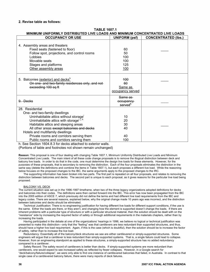
36 2007 ICC FINAL ACTION AGENDA
2. Revise table as follows:
TABLE 1607.1 MINIMUM UNIFORMLY DISTRIBUTED LIVE LOADS AND MINIMUM CONCENTRATED LIVE LOADS
OCCUPANCY OR USE UNIFORM (psf) CONCENTRATED (lbs.) 4. Assembly areas and theaters
Fixed seats (fastened to floor) Follow spot, projections, and control rooms Lobbies Movable seats Stages and platforms Other assembly areas
60 50 100 100 125 100
____
5. Balconies (exterior) and decksh
On one- and two-family residences only, and not exceeding 100 sq ft
100 60
Same as occupancy served
____
9. Decks
Same as occupancy
servedh
____
28. Residential One- and two-family dwellings
Uninhabitable attics without storagei Uninhabitable attics with storagei, j, k Habitable attics and sleeping areas All other areas except balconies and decks
Hotels and multifamily dwellings Private rooms and corridors serving them Public rooms and corridors serving them
10 20 30 40
40 100
____
h. See Section 1604.8.3 for decks attached to exterior walls. (Portions of table and footnotes not shown remain unchanged) Reason: This proposal is one of four dealing with changing Table 1607.1, Minimum Uniformly Distributed Live Loads and Minimum Concentrated Live Loads. The main intent of all these code change proposals is to remove the illogical distinction between deck and balcony live loads. In order to do that in the code, one must determine the design live loads for these elements. However, for the purposes of these proposals, that is secondary to removing the distinction. Each of the four proposals eliminates the distinction in the same way (delete the definitions and combine the items in Table 1607.1), but each proposes a different live load. While the reasoning below focuses on the proposed changes to the IBC, the same arguments apply to the proposed changes to the IRC.
The supporting information has been broken into two parts. The first part is repeated on all four proposals, and relates to removing the distinction between balconies and decks. The second part is unique to each proposal, as it gives reasons for the particular live load being proposed.
BALCONY VS. DECK
The current situation was set up in the 1996-1997 timeframe, when two of the three legacy organizations adopted definitions for decks and balconies into their codes. The definitions were then carried forward into the IBC. This error has now been propagated from the IBC into the 2005 edition of ASCE 7, which previously did not define the terms and had different live load requirements from the IBC and legacy codes. There are several reasons, explained below, why the original change made 10 years ago was incorrect, and the distinction between balconies and decks should be eliminated.
Technical Justification: There is no engineering justification for having different live loads for different support conditions, if the use is the same. Either the loads are there, or they aren’t, and changing how the element is supported doesn’t change the loads. If there are inherent problems with a particular type of structure or with a particular structural material, then the solution should be dealt with on the “resistance” side by increasing the required factor of safety or through additional requirements in the materials chapters, rather than by increasing the loads.
Having participated in the debate at one of the organizations’ hearings in 1996, we believe no logical or technical justification was presented to make this distinction—only that the “feeling” was that cantilevers are less redundant than supported structures, and thus, should have a higher live load requirement. Again, if this is the case (which is doubtful), then the solution should be to increase the factor of safety, rather than to increase the live load.
Redundancy: Essentially all of the balcony/deck structures we see are either cantilevered or simply-supported structures. Some engineers will argue that a cantilever is less redundant than simply-supported systems. That is, a single failure could lead to collapse. However, from an engineering standpoint as applied to these structures, a simply-supported structure has no added redundancy compared to a cantilever.
Safety Record: The safety record of cantilevers is better than decks. If simply-supported systems are more redundant than cantilevers, one would expect to see increased safety as reflected by fewer collapses. However, in a Google search for “deck/balcony/failure/collapse”, we were only able to find one instance of cantilevered balconies that failed, in Australia. In contrast to that single case of a cantilevered balcony failure, there were many reports of deck failures.

2007 ICC FINAL ACTION AGENDA 37
With most of the reports of failures, it could not be distinguished whether the structure was cantilevered or not. However, where it could be distinguished that the failed structure was a “deck” or a “balcony” per the definitions in the code, the vast majority were “deck” failures. Usually, the deck failures occurred at the connection of the deck to the building due to incorrect or poor design (e.g., nails in withdrawal, incorrect type of joist hanger) or by deterioration of the connection components. In the reports for some cases, it was questioned whether proper permits had been obtained. In one recent case in the state of Washington, the posts supporting the structure were not connected to anything at the ground level, and they “kicked out”. In the one balcony failure case, the concrete balconies apparently developed a crack at the support allowing moisture to rust the rebar. Neither of these causes of failure (poor design or deterioration) can be attributed to a lack of redundancy. It is notable that where the reports discussed loading conditions, it was to state the failures were not caused by overload conditions.
Consistency: The live loads for balconies and decks are inconsistent with all the other loads in the Live Load table (IBC Table, 1607.1, ASCE 7-05 Table 4-1), in that no other loads are based on the structural support conditions. All others are based on occupancy or use (which is the heading in the table). Logically, if cantilevers are inherently dangerous, then all other items in the table should have separate loads for cantilevers versus other support conditions.
Definitions: The definitions were inserted into the two legacy codes because the live load tables required different loads for balconies versus decks, similar to ASCE 7. Once it has been demonstrated there is not a reason to apply different loading conditions to balconies versus decks, there is no need to define the terms.
It is to be noted, however, there is not an exact match between the legacy code definitions and what appears to be the intended application in ASCE 7. Table 4-1 of earlier editions of ASCE 7 has an item for “Balconies (exterior)” (live load = 100 psf, or 60 psf for small residential balconies), and an item for “Decks (patio and roof)” (live load = “same as area served, or for the type of occupancy accommodated”). One legacy code deleted the parenthetical “patio and roof” from the “deck” item. The second retained it, but inserted the same definitions. It appears the definitions inserted into the legacy codes were in error as compared to ASCE 7, because “decks” were supposed to be patios (decks on grade?) or roof decks.
However, even if one were to redefine “balcony” and “deck” to fit with what appears to be the intent of ASCE 7, there does not appear to be justification for having different loads for them, as they will most likely be used similarly.
IBC versus ASCE 7: Some will argue that IBC and ASCE 7 should not be different, and that it is really the province of ASCE 7 to determine appropriate live loads. In general, we agree with this philosophy, and it is our intent to submit similar proposals to the ASCE 7 process. There are two reasons why we believe ICC should act now:
1. It is our understanding that the primary reason for the deck and balcony modification to the live load table of ASCE 7-05 was so it would match the organization contained in the 2003 IBC. As stated above, this just means that errors made in legacy codes have been propagated now into ASCE 7. Therefore, if ASCE 7 has been changed once to match the IBC, there is no reason why the IBC can’t lead the way again.
2. It is our understanding that the next edition of ASCE 7 is not scheduled to come out until 2010. If one assumes that ASCE 7 fixes this problem in their process in that cycle (and there is no guarantee that it will), this means it will not be until the 2012 edition of the IBC that the fix will be included in the code, which will mean it will be 2013 before many jurisdictions actually adopt the code. That is too long to be propagating this error.
DESIGN LIVE LOAD FOR BALCONIES AND DECKS:
Once the premise has been accepted that the loads should not differ based on structural support conditions, the question is, what is the appropriate design live load for these structures?
The premise behind this option is if a deck can be designed to the same load as the occupancy it serves (as the code currently allows), the same should be allowed for balconies. If the balcony/deck serves a one-family dwelling, the minimum live load will be 40 psf. If it serves a private office, the live load is 50 psf. If it is an assembly area such as a roof deck, then it can be argued that it should be designed for 100 psf. The addition proposed to the Assembly item in Table 1607.1 will clarify this requirement, as well as for other assembly areas not currently covered by the table. It is significant to note that where the reports turned up in the Google search discussed loading conditions, it was to state that the decks did not fail due to overload conditions.
The callout for Footnote h in Table 1607.2 has been moved (attached to “decks” instead of the load), since it only applies to decks. The changes being proposed in Part II for the IRC are for consistency with the terminology used in the IBC and with the live loads in
the Part I proposal. Cost Impact: The code change proposal will not increase the cost of construction. Committee Action: Disapproved Committee Reason: This code change was disapproved because the revision made by S10-06/07 was preferred. Assembly Action: None Individual Consideration Agenda This item is on the agenda for individual consideration because a public comment was submitted. Public Comment: Gary Ehrlich, P.E., National Association of Home Builders, requests Approval as Submitted for Part I. Commenter=s Reason: As discussed at the hearings in Orlando, there has not been substantial evidence of deck or balcony failures due to overloading of the floor joists, girders, or piers. In fact, the evidence presented by NCSEA suggests that decks and balconies only see a live load of 20 psf even in a heavily-loaded state. The documented failures have been at the deck ledger connection to the floor framing and would likely have happened regardless of the design live load for decks and balconies. This proposal would allow decks in R-3 and

38 2007 ICC FINAL ACTION AGENDA
R-4 occupancies and IRC dwellings forced to use the IBC provisions to be designed for a 40psf live load just as they would under the IRC. This would allow an engineer to make use of design aids developed for 40psf deck live loads such as the residential ledger table being implemented in the IRC. NAHB asks for your support in approving this proposal as submitted and reversing the committee’s action. Final Action: AS AM AMPC D
S9-06/07, Part II IRC R202, Table R 301.5 Proposed Change as Submitted: Proponent: Jonathan C. Siu, City of Seattle, representing Washington Association of Building Officials PART II – IRC BUILDING/ENERGY 1. Delete definitions without substitution:
SECTION R202 [B] BALCONY, EXTERIOR. An exterior floor projecting from and supported by a structure without additional independent supports.
[B] DECK. An exterior floor system supported on at least two opposing sides by an adjoining structure and/or posts, piers, or other independent supports. 2. Revise table as follows:
TABLE R301.5 MINIMUM UNIFORMLY DISTRIBUTED LIVE LOADS
(in pounds per square foot) USE LIVE LOAD
Balconies (exterior) and deckse 40
Exterior balconies 60 e. See Section R502.2.1 for decks attached to exterior walls. (Portions of table and footnotes not shown do not change) Reason: This proposal is one of four dealing with changing Table 1607.1, Minimum Uniformly Distributed Live Loads and Minimum Concentrated Live Loads. The main intent of all these code change proposals is to remove the illogical distinction between deck and balcony live loads. In order to do that in the code, one must determine the design live loads for these elements. However, for the purposes of these proposals, that is secondary to removing the distinction. Each of the four proposals eliminates the distinction in the same way (delete the definitions and combine the items in Table 1607.1), but each proposes a different live load. While the reasoning below focuses on the proposed changes to the IBC, the same arguments apply to the proposed changes to the IRC.
The supporting information has been broken into two parts. The first part is repeated on all four proposals, and relates to removing the distinction between balconies and decks. The second part is unique to each proposal, as it gives reasons for the particular live load being proposed.
BALCONY VS. DECK The current situation was set up in the 1996-1997 timeframe, when two of the three legacy organizations adopted definitions for decks and balconies into their codes. The definitions were then carried forward into the IBC. This error has now been propagated from the IBC into the 2005 edition of ASCE 7, which previously did not define the terms and had different live load requirements from the IBC and legacy codes. There are several reasons, explained below, why the original change made 10 years ago was incorrect, and the distinction between balconies and decks should be eliminated.
Technical Justification: There is no engineering justification for having different live loads for different support conditions, if the use is the same. Either the loads are there, or they aren’t, and changing how the element is supported doesn’t change the loads. If there are inherent problems with a particular type of structure or with a particular structural material, then the solution should be dealt with on the “resistance” side by increasing the required factor of safety or through additional requirements in the materials chapters, rather than by increasing the loads.
Having participated in the debate at one of the organizations’ hearings in 1996, we believe no logical or technical justification was presented to make this distinction—only that the “feeling” was that cantilevers are less redundant than supported structures, and thus, should have a higher live load requirement. Again, if this is the case (which is doubtful), then the solution should be to increase the factor of safety, rather than to increase the live load.

2007 ICC FINAL ACTION AGENDA 39
Redundancy: Essentially all of the balcony/deck structures we see are either cantilevered or simply-supported structures. Some engineers will argue that a cantilever is less redundant than simply-supported systems. That is, a single failure could lead to collapse. However, from an engineering standpoint as applied to these structures, a simply-supported structure has no added redundancy compared to a cantilever.
Safety Record: The safety record of cantilevers is better than decks. If simply-supported systems are more redundant than cantilevers, one would expect to see increased safety as reflected by fewer collapses. However, in a Google search for “deck/balcony/failure/collapse”, we were only able to find one instance of cantilevered balconies that failed, in Australia. In contrast to that single case of a cantilevered balcony failure, there were many reports of deck failures.
With most of the reports of failures, it could not be distinguished whether the structure was cantilevered or not. However, where it could be distinguished that the failed structure was a “deck” or a “balcony” per the definitions in the code, the vast majority were “deck” failures. Usually, the deck failures occurred at the connection of the deck to the building due to incorrect or poor design (e.g., nails in withdrawal, incorrect type of joist hanger) or by deterioration of the connection components. In the reports for some cases, it was questioned whether proper permits had been obtained. In one recent case in the state of Washington, the posts supporting the structure were not connected to anything at the ground level, and they “kicked out”. In the one balcony failure case, the concrete balconies apparently developed a crack at the support allowing moisture to rust the rebar. Neither of these causes of failure (poor design or deterioration) can be attributed to a lack of redundancy. It is notable that where the reports discussed loading conditions, it was to state the failures were not caused by overload conditions.
Consistency: The live loads for balconies and decks are inconsistent with all the other loads in the Live Load table (IBC Table, 1607.1, ASCE 7-05 Table 4-1), in that no other loads are based on the structural support conditions. All others are based on occupancy or use (which is the heading in the table). Logically, if cantilevers are inherently dangerous, then all other items in the table should have separate loads for cantilevers versus other support conditions.
Definitions: The definitions were inserted into the two legacy codes because the live load tables required different loads for balconies versus decks, similar to ASCE 7. Once it has been demonstrated there is not a reason to apply different loading conditions to balconies versus decks, there is no need to define the terms.
It is to be noted, however, there is not an exact match between the legacy code definitions and what appears to be the intended application in ASCE 7. Table 4-1 of earlier editions of ASCE 7 has an item for “Balconies (exterior)” (live load = 100 psf, or 60 psf for small residential balconies), and an item for “Decks (patio and roof)” (live load = “same as area served, or for the type of occupancy accommodated”). One legacy code deleted the parenthetical “patio and roof” from the “deck” item. The second retained it, but inserted the same definitions. It appears the definitions inserted into the legacy codes were in error as compared to ASCE 7, because “decks” were supposed to be patios (decks on grade?) or roof decks.
However, even if one were to redefine “balcony” and “deck” to fit with what appears to be the intent of ASCE 7, there does not appear to be justification for having different loads for them, as they will most likely be used similarly.
IBC versus ASCE 7: Some will argue that IBC and ASCE 7 should not be different, and that it is really the province of ASCE 7 to determine appropriate live loads. In general, we agree with this philosophy, and it is our intent to submit similar proposals to the ASCE 7 process. There are two reasons why we believe ICC should act now:
1. It is our understanding that the primary reason for the deck and balcony modification to the live load table of ASCE 7-05 was so it would match the organization contained in the 2003 IBC. As stated above, this just means that errors made in legacy codes have been propagated now into ASCE 7. Therefore, if ASCE 7 has been changed once to match the IBC, there is no reason why the IBC can’t lead the way again.
2. It is our understanding that the next edition of ASCE 7 is not scheduled to come out until 2010. If one assumes that ASCE 7 fixes this problem in their process in that cycle (and there is no guarantee that it will), this means it will not be until the 2012 edition of the IBC that the fix will be included in the code, which will mean it will be 2013 before many jurisdictions actually adopt the code. That is too long to be propagating this error.
DESIGN LIVE LOAD FOR BALCONIES AND DECKS: Once the premise has been accepted that the loads should not differ based on structural support conditions, the question is, what is the appropriate design live load for these structures?
The premise behind this option is if a deck can be designed to the same load as the occupancy it serves (as the code currently allows), the same should be allowed for balconies. If the balcony/deck serves a one-family dwelling, the minimum live load will be 40 psf. If it serves a private office, the live load is 50 psf. If it is an assembly area such as a roof deck, then it can be argued that it should be designed for 100 psf. The addition proposed to the Assembly item in Table 1607.1 will clarify this requirement, as well as for other assembly areas not currently covered by the table. It is significant to note that where the reports turned up in the Google search discussed loading conditions, it was to state that the decks did not fail due to overload conditions.
The callout for Footnote h in Table 1607.2 has been moved (attached to “decks” instead of the load), since it only applies to decks. The changes being proposed in Part II for the IRC are for consistency with the terminology used in the IBC and with the live loads in
the Part I proposal. Cost Impact: The code change proposal will not increase the cost of construction. Committee Action: Approved as Submitted Committee Reason: This change serves to eliminate the differences between balcony and deck live loads and adds needed clarity to the code language. Assembly Action: None Individual Consideration Agenda This item is on the agenda for individual consideration because a public comment was submitted. Public Comment: Daniel J. Walker, Thomas Associates, Inc, representing National Sunroom Association, requests Disapproval for Part II.

40 2007 ICC FINAL ACTION AGENDA
Commenter=s Reason: If these provisions are adopted, using the IRC one could design a deck or balcony for 40 psf, while under the IBC he/she would be required to design for 100 psf. We feel that for both decks and balconies there tends to be more load applied at the end of the structure (away from the building). This is because people tend to congregate toward the edge of a deck or balcony, stack wood at the edge, or place plants there. The difference between balconies and decks is that if you put a large load at the end of a deck, the load will be carried by a supporting element that is fairly close to the load. With a balcony, the load is transferred back to the house, which results in a significant increase in stress compared to the same load case for a deck. We agree with the author’s discussion on safety record, but we believe this is a connection issue that should be addressed through proper construction and detailing, rather than changes to the design loads. Final Action: AS AM AMPC D
S10-06/07, Part I 1602, 202, Table 1607.1; IRC R202, Table R301.5 Proposed Change as Submitted: PART II DID NOT RECEIVE A PUBLIC COMMENT AND IS ON THE CONSENT AGENDA. PART II IS REPRODUCED HERE FOR INFORMATION PURPOSES ONLY. Proponent: Jonathan C. Siu, City of Seattle, representing Washington Association of Building Officials PART I – IBC STRUCTURAL 1. Delete definitions without substitution:
SECTION 202 DEFINITIONS
BALCONY, EXTERIOR. See Section 1602.1. DECK. See Section 1602.1.
SECTION 1602 DEFINITIONS AND NOTATIONS
1602.1 Definitions. The following words and terms shall, for the purposes of this chapter, have the meanings shown herein. BALCONY, EXTERIOR. An exterior floor projecting from and supported by a structure without additional independent supports. DECK. An exterior floor supported on at least two opposing sides by an adjacent structure, and/or posts, piers or other independent supports. 2. Revise table as follows:
TABLE 1607.1 MINIMUM UNIFORMLY DISTRIBUTED LIVE LOADS AND
MINIMUM CONCENTRATED LIVE LOADS OCCUPANCY OR USE UNIFORM
(psf) CONCENTRATED (lbs.)
4. Assembly areas and theaters [unchanged]
5. Balconies (exterior) and decksh On one- and two-family residences only, and not exceeding 100 sq ft
100 60
____
9. Decks Same as occupancy
servedh
____
28. Residential [unchanged]
h. See Section 1604.8.3 for decks attached to exterior walls. (Portions of table and footnotes not shown remain unchanged)

2007 ICC FINAL ACTION AGENDA 41
PART II – IRC 1. Delete definitions without substitution:
SECTION R202 [B] BALCONY, EXTERIOR. An exterior floor projecting from and supported by a structure without additional independent supports. [B] DECK. An exterior floor system supported on at least two opposing sides by an adjoining structure and/or posts, piers, or other independent supports. 2. Revise table as follows:
TABLE R301.5 MINIMUM UNIFORMLY DISTRIBUTED LIVE LOADS
(in pounds per square foot) USE LIVE LOAD
Deckse 40 Exterior Balconies (exterior) and deckse 60
e. See Section R502.2.1 for decks attached to exterior walls. (Portions of table and footnotes not shown do not change) Reason: This proposal is one of four dealing with changing Table 1607.1, Minimum Uniformly Distributed Live Loads and Minimum Concentrated Live Loads. The main intent of all these code change proposals is to remove the illogical distinction between deck and balcony live loads. In order to do that in the code, one must determine the design live loads for these elements. However, for the purposes of these proposals, that is secondary to removing the distinction. Each of the four proposals eliminates the distinction in the same way (delete the definitions and combine the items in Table 1607.1), but each proposes a different live load. While the reasoning below focuses on the proposed changes to the IBC, the same arguments apply to the proposed changes to the IRC.
The supporting information has been broken into two pieces. The first part is repeated on all four proposals, and relates to removing the distinction between balconies and decks. The second part is unique to each proposal, as it gives reasons for the particular live load being proposed.
BALCONY VS. DECK
The current situation was set up in the 1996-1997 timeframe, when two of the three legacy organizations adopted definitions for decks and balconies into their codes. The definitions were then carried forward into the IBC. This error has now been propagated from the IBC into the 2005 edition of ASCE 7, which previously did not define the terms and had different live load requirements from the IBC and legacy codes. There are several reasons, explained below, why the original change made 10 years ago was incorrect, and the distinction between balconies and decks should be eliminated.
Technical Justification: There is no engineering justification for having different live loads for different support conditions, if the use is the same. Either the loads are there, or they aren’t, and changing how the element is supported doesn’t change the loads. If there are inherent problems with a particular type of structure or with a particular structural material, then the solution should be dealt with on the “resistance” side by increasing the required factor of safety or through additional requirements in the materials chapters, rather than by increasing the loads.
Having participated in the debate at one of the organizations’ hearings in 1996, we believe no logical or technical justification was presented to make this distinction—only that the “feeling” was that cantilevers are less redundant than supported structures, and thus, should have a higher live load requirement. Again, if this is the case (which is doubtful), then the solution should be to increase the factor of safety, rather than to increase the live load.
Redundancy: Essentially all of the balcony/deck structures we see are either cantilevered or simply-supported structures. Some engineers will argue that a cantilever is less redundant than simply-supported systems. That is, a single failure could lead to collapse. However, from an engineering standpoint as applied to these structures, a simply-supported structure has no added redundancy compared to a cantilever.
Safety Record: The safety record of cantilevers is better than decks. If simply-supported systems are more redundant than cantilevers, one would expect to see increased safety as reflected by fewer collapses. However, in a Google search for “deck/balcony/failure/collapse”, we were only able to find one instance of cantilevered balconies that failed, in Australia. In contrast to that single case of a cantilevered balcony failure, there were many reports of deck failures.
With most of the reports of failures, it could not be distinguished whether the structure was cantilevered or not. However, where it could be distinguished that the failed structure was a “deck” or a “balcony” per the definitions in the code, the vast majority were “deck” failures. Usually, the deck failures occurred at the connection of the deck to the building due to incorrect or poor design (e.g., nails in withdrawal, incorrect type of joist hanger) or by deterioration of the connection components. In the reports for some cases, it was questioned whether proper permits had been obtained. In one recent case in the state of Washington, the posts supporting the structure were not connected to anything at the ground level, and they “kicked out”. In the one balcony failure case, the concrete balconies apparently developed a crack at the support allowing moisture to rust the rebar. Neither of these causes of failure (poor design or deterioration) can be attributed to a lack of redundancy. It is notable that where the reports discussed loading conditions, it was to state the failures were not caused by overload conditions.
Consistency: The live loads for balconies and decks are inconsistent with all the other loads in the Live Load table (IBC Table, 1607.1, ASCE 7-05 Table 4-1), in that no other loads are based on the structural support conditions. All others are based on occupancy or use (which is the heading in the table). Logically, if cantilevers are inherently dangerous, then all other items in the table should have separate loads for cantilevers versus other support conditions.

42 2007 ICC FINAL ACTION AGENDA
Definitions: The definitions were inserted into the two legacy codes because the live load tables required different loads for balconies versus decks, similar to ASCE 7. Once it has been demonstrated there is not a reason to apply different loading conditions to balconies versus decks, there is no need to define the terms.
It is to be noted, however, there is not an exact match between the legacy code definitions and what appears to be the intended application in ASCE 7. Table 4-1 of earlier editions of ASCE 7 has an item for “Balconies (exterior)” (live load = 100 psf, or 60 psf for small residential balconies), and an item for “Decks (patio and roof)” (live load = “same as area served, or for the type of occupancy accommodated”). One legacy code deleted the parenthetical “patio and roof” from the “deck” item. The second retained it, but inserted the same definitions. It appears the definitions inserted into the legacy codes were in error as compared to ASCE 7, because “decks” were supposed to be patios (decks on grade?) or roof decks. However, even if one were to redefine “balcony” and “deck” to fit with what appears to be the intent of ASCE 7, there does not appear to be justification for having different loads for them, as they will most likely be used similarly.
IBC versus ASCE 7: Some will argue that IBC and ASCE 7 should not be different, and that it is really the province of ASCE 7 to determine appropriate live loads. In general, we agree with this philosophy, and it is our intent to submit similar proposals to the ASCE 7 process. There are two reasons why we believe ICC should act now:
1. It is our understanding that the primary reason for the deck and balcony modification to the live load table of ASCE 7-05 was so it would match the organization contained in the 2003 IBC. As stated above, this just means that errors made in legacy codes have been propagated now into ASCE 7. Therefore, if ASCE 7 has been changed once to match the IBC, there is no reason why the IBC can’t lead the way again.
2. It is our understanding that the next edition of ASCE 7 is not scheduled to come out until 2010. If one assumes that ASCE 7 fixes this problem in their process in that cycle (and there is no guarantee that it will), this means it will not be until the 2012 edition of the IBC that the fix will be included in the code, which will mean it will be 2013 before many jurisdictions actually adopt the code. That is too long to be propagating this error.
DESIGN LIVE LOAD FOR BALCONIES AND DECKS:
Once the premise has been accepted that the loads should not differ based on structural support conditions, the question is, what is the appropriate design live load for these structures?
This option is based on taking the most conservative approach to determine the required design live load. That is, since balconies were required to be designed to 100 psf or 60 psf, decks will be required to be designed to the same load. It is our understanding from previous discussions at code change hearings that the 60 psf is derived from the weight of a stack of firewood. However, it is to be noted that none of the reports turned up in the Google search listed overloading due to stacked firewood as a cause of failure.
The callout for Footnote h in Table 1607.2 has been moved (attached to “decks” instead of the load), since it only applies to decks. The changes being proposed in Part II for the IRC are for consistency with the terminology used in the IBC and with the live loads in
the Part I proposal. Cost Impact: The code change proposal will increase the cost of construction. PART I – IBC Committee Action: Approved as Submitted Committee Reason: This code change removes the distinction between deck and balcony live loads in Table 1607.1, by requiring the minimum live load formerly applicable only to balconies. This approach was preferred over the options provided by S9-06/07, S11-06/07 and S12-06/07 because there was no justification provided for reducing the balcony live load. Assembly Action: None PART II — IRC Committee Action: Disapproved Committee Reason: The committee preferred to disapprove this code change proposal and support the language proposed in S9-06/07. Assembly Action: None Individual Consideration Agenda This item is on the agenda for individual consideration because public comments were submitted. Public Comment 1: Gary Ehrlich, P.E., National Association of Home Builders, requests Disapproval for Part I. Commenter=s Reason: This proposal creates an unreasonably conservative standard for simply-supported decks attached to one- and two-family dwellings and townhouses constructed under IBC provisions. The proposal would increase the live load requirement for these decks by more than a factor of two, from the current 40 psf to 100 psf. The only exception would be small decks less than 100sf in area, and those would still be subject to an increased load requirement, from 40psf to 60psf. A number of design aids exist for residential decks that use 40psf live loads as their basis, including the testing-backed residential ledger table being implemented in the IRC. Increasing the live load for decks means an engineer designing for an R-3 or R-4 residential occupancy under the IBC would not be able to use these design aids. The same situation would apply for an engineer or designer of a dwelling that is forced into the IBC from the IRC due to wind or seismic requirements.

2007 ICC FINAL ACTION AGENDA 43
No evidence was presented at the hearings in Orlando regarding deck or balcony failures due to overloading of the floor joists, girders, or piers. The documented failures have been at the deck ledger connection to the floor framing and would likely have happened regardless of the design live load. There is no need to subject simply-supported residential decks to this overly conservative standard for design. NAHB asks for your support in disapproving S10 and reversing the committee’s action. Public Comment 2: Daniel J. Walker, Thomas Associates, Inc., representing National Sunroom Association, requests Disapproval for Part I. Commenter=s Reason: If these provisions are adopted, using the IRC one could design a deck or balcony for 40 psf, while under the IBC he/she would be required to design for 100 psf. We feel that for both decks and balconies there tends to be more load applied at the end of the structure (away from the building). This is because people tend to congregate toward the edge of a deck or balcony, stack wood at the edge, or place plants there. The difference between balconies and decks is that if you put a large load at the end of a deck, the load will be carried by a supporting element that is fairly close to the load. With a balcony, the load is transferred back to the house, which results in a significant increase in stress compared to the same load case for a deck. We agree with the author’s discussion on safety record, but we believe this is a connection issue that should be addressed through proper construction and detailing, rather than changes to the design loads. Final Action: AS AM AMPC D
S16-06/07 1609.1.1 Proposed Change as Submitted: Proponents: Paul K. Heilstedt, P.E., Chair, representing ICC Code Technology Committee (CTC) Gerry Jones/Herman Brice, Co-Chairs, NIBS/MMC Committee for Translating the NIST World Trade Center Investigation Recommendations into Building Codes 1. Revise as follows: 1609.1.1 Determination of wind loads: Wind loads on every building or structure shall be determined in accordance with Chapter 6 of ASCE 7. The type of opening protection required, the basic wind speed and the exposure category for a site is permitted to be determined in accordance with Section 1609 or ASCE 7. Wind shall be assumed to come from any horizontal direction and wind pressures shall be assumed to act normal to the surface considered.
Exceptions:
1. Subject to the limitations of Section 1609.1.1.1, the provisions of SBCCI SSTD 10 Standard for Hurricane Resistant Residential Construction shall be permitted for applicable Group R-2 and R-3 buildings.
2. Subject to the limitations of Section 1609.1.1.1, residential structures using the provisions of the AF&PA WFCM.
3. Designs using NAAMM FP 1001. 4. Designs using TIA/EIA-222 for antenna-supporting structures and antennas. 5. Designs using wind tunnel testing in accordance with Section 1609.1.1.2
1609.1.1.1 Applicability. The provisions of SSTD 10 are applicable only to buildings located within Exposure B or C as defined in Section 1609.4. The provisions of SSTD 10 and the AF&PA Wood Frame construction Manual for One- and Two-Family Dwellings shall not apply to buildings sited on the upper half of an isolated hill, ridge or escarpment meeting the following conditions:
1. The hill, ridge or escarpment is 60 feet (18 288 mm) or higher if located in Exposure B or 30 feet (9144
mm) or higher if located in Exposure C; 2. The hill, ridge or escarpment is 60 feet (18 288 mm) or higher if located in Exposure B or 30 feet (9144
mm) or higher if located in Exposure C;. The maximum average slope of the hill exceeds 10 percent; and
3. The hill, ridge or escarpment is unobstructed upwind by other such topographic features for a distance from the high point of 50 times the height of the hill or 1 mile (1.61 km), whichever is greater.
1609.1.1.2 Wind tunnel testing. Where wind tunnel testing is used to determine design wind loads, such testing shall be in accordance with ASCE xx.
44 2007 ICC FINAL ACTION AGENDA
2. Add standard to Chapter 35 as follows: ASCE xx-yy Wind Tunnel Testing Reason: The ICC Board established the ICC Code Technology Committee (CTC) as the venue to discuss contemporary code issues in a committee setting which provides the necessary time and flexibility to allow for full participation and input by any interested party. The code issues are assigned to the CTC by the ICC Board as “areas of study”. Information on the CTC, including: meeting agendas; minutes; reports; resource documents; presentations; and all other materials developed in conjunction with the CTC effort can be downloaded from the following website: http://www.iccsafe.org/cs/cc/ctc/index.html Since its inception, the CTC has held six meetings - all open to the public. This proposed change is a result of the CTC’s investigation of the area of study entitled “Review of NIST WTC Recommendations”. The scope of the activity is noted as: Review the recommendations issued by NIST in its report entitled “Final Report on the Collapse of the World Trade Center Towers”, issued September 2005, for applicability to the building environment as regulated by the I-Codes.
This proposal is intended to address NIST recommendation 2. For this specific proposed change, CTC is working in cooperation with the NIBS/MMC Committee to Translate the NIST World Trade Center Investigation Recommendations for the Model Codes. The CTC notes in their investigation that many of the recommendations contained in the NIST report require additional information for the CTC to further investigate. As such, CTC intends to continue to study the other NIST recommendations.
NIST Recommendation 2 recommends that nationally accepted performance standards be developed for: (1) conducting wind tunnel testing of prototype structures based on sound technical methods that result in repeatable and reproducible results among testing laboratories; and (2) estimating wind loads and their effects on tall buildings for use in design, based on wind tunnel testing data and directional wind speed data. The IBC requires that wind loads be determined in accordance with Chapter 6 of ASCE 7, with specific exceptions depending on the size, configuration and location of the building. Section 6.1 of ASCE 7-05 provides three procedures to determine design wind loads: Method 1- Simplified Procedure; Method 2- Analytical Procedure; and Method 3- Wind Tunnel Procedure. Due to unique wind load considerations for certain building configurations and locations, Section 6.5.2 of ASCE 7 - 05 further mandates compliance with either the wind tunnel procedure of Section 6.6 of ASCE 7 or requires the design to be based on recognized literature documenting the wind load effects. Section 6.6 of ASCE does not currently prescribe specific wind tunnel test procedures. These are being developed by an ASCE Wind Tunnel Testing standard committee. The purpose of this change is not to mandate wind tunnel testing in the IBC, but rather to achieve uniformity in results where the design involves wind tunnel testing – either as required by ASCE 7 or where the designer determines that wind tunnel testing is to be used to determine the wind loads. As of the submission of this proposal, it is CTC’s understanding that the wind tunnel test standard is not complete but is under development. Bibliography: Interim Report No. 1 of the CTC, Area of Study – Review of NIST WTC Recommendations, March 9, 2006. National Institute of Standards and Technology. Final Report of the National Construction Safety Team on the Collapses of the World Trade Center Towers. United States Government Printing Office: Washington, D.C. September 2005. Cost Impact: The code change proposal will not increase the cost of construction Analysis: Results of review of the proposed standard(s) will be posted on the ICC website by August 20, 2006. Note: The following analysis was not in the Code Change Proposal book but was published in the “Errata to the 2006/2007 Proposed Changes to the International Codes and Analysis of Proposed Referenced Standards” provided at the code development hearings: Analysis: Review of proposed new standard indicated that, in the opinion of ICC staff, the standard did not comply with ICC criteria for referenced standards, Section 3.6.3-1 readily available. Committee Action: Disapproved Committee Reason: This proposal was disapproved because it would incorrectly reference the wind tunnel test standard as an exception to the ASCE 7 wind load requirements. Doing so would allow designers to circumvent other applicable wind load requirements by performing a wind tunnel test. In addition the proposed standard is not in compliance with the ICC code development process since it is not yet readily available. Assembly Action: None Individual Consideration Agenda This item is on the agenda for individual consideration because a public comment was submitted. Public Comment: Paul Heilstedt, PE, Chair, Code Technology Committee (CTC), IBHS and NIBS/MMC requests Approval as Modified by this public comment.

2007 ICC FINAL ACTION AGENDA 45
Modify proposal as follows: 1609.1.1.2 Wind tunnel testing. Where wind tunnel testing is used to determine design wind loads, such testing shall be in accordance with ASCE/SEI 49. The minimum design wind load shall not be less than the minimum prescribed by ASCE 7. The lower limit on pressures for main wind-force resisting systems and components and cladding shall be in accordance with Sections 1609.1.1.2.1 and 1609.1.1.2.2. 1609.1.1.2.1 Lower limits on main wind-force-resisting system. Base overturning moments determined from wind tunnel testing shall be limited to not less than 80 percent of the design base overturning moment determined in accordance with Section 6.5 of ASCE 7, unless specific testing is performed that demonstrates it is the aerodynamic coefficient of the building, rather than shielding from other structures, that is responsible for the lower values. The 80 percent limit may be adjusted by the ratio of the frame load at critical wind directions as determined from wind tunnel testing without specific adjacent buildings, but including appropriate upwind roughness, to that determined in Section 6.5 of ASCE 7. 1609.1.1.2.2 Lower limits on components and cladding. The design pressures for components and cladding on walls or roofs shall be selected as the greater of the wind tunnel test results or 80 percent or the pressure obtained for Zone 4 for walls and Zone 1 for roofs as determined in Section 6.5 of ASCE 7, unless specific testing is performed that demonstrates it is the aerodynamic coefficient of the building, rather than shielding from nearby structures, that is responsible for the lower values. Alternatively, limited tests at a few wind directions without specific adjacent buildings, but in the presence of an appropriate upwind roughness, shall be permitted to be used to demonstrate that the lower pressures are due to the shape of the building and not to shielding. Chapter 35: ASCE/SEI 49-07 Wind Tunnel Testing for Buildings and Other Structures (Portions of the proposal not shown remain unchanged) Commenter=s Reason: The committee correctly noted that ASCE 7 prescribes a minimum design load. This load is 10 psf in accordance with Section 6.1.4.1 of ASCE 7. In code change S17-06/07, the proponent of the change provides the criteria to be used in conjunction with wind tunnel testing. This public comment is merely correlating the text of S16, including the proposed new referenced standard, with the text that was approved as modified in S17 by the IBC Structural committee. As to availability of the standard, ASCE has indicated that the public comment phase of the standard development has been completed and the standard will be published and available prior to the Final Action Hearing. If the standard is not available, this public comment will be withdrawn. If this public comment is successful and the action taken on S17 stands, the correlated text between the two code changes should include the text of exception 5 from S16 as this text refers to the new referenced standard. Final Action: AS AM AMPC D
S18-06/07 1609.1.2 Proposed Change as Submitted: Proponent: Edwin T. Huston, Smith & Huston Inc., representing National Council of Structural Engineering Associations Revise as follows: 1609.1.2 Protection of openings. In wind-borne debris regions, glazing in buildings shall be impact-resistant or protected with an impact-resistant covering meeting the requirements of an approved impact-resistant standard or ASTM E 1996 and ASTM E 1886 referenced herein as follows:
1. Glazed openings located within 30 feet (9144 mm) of grade shall meet the requirements of the Large Missile Test of ASTM E 1996.
2. Glazed openings located more than 30 feet (9144 mm) above grade shall meet the provisions of the Small Missile Test of ASTM E 1996.
Exceptions:
1. Wood structural panels with a minimum thickness of 7/16 inch (11.1 mm) and maximum panel span
of 8 ` feet (2438 mm) shall be permitted for opening protection in one- and two-story buildings classified as Group R-3 or R-4 occupancy. Panels shall be precut so that they shall be attached to the framing surrounding the opening containing the product with the glazed opening. Panels shall be secured with the attachment hardware provided. Attachments shall be designed to resist the

46 2007 ICC FINAL ACTION AGENDA
components and cladding loads determined in accordance with the provisions of ASCE 7. Attachment in accordance with Table 1609.1.2 is permitted for buildings with a mean roof height of 33 feet (10058 mm) or less where wind speeds do not exceed 130 mph (57.2 m/s).
2. Glazing in Occupancy Category I buildings as defined in Section 1604.5, including greenhouses that are occupied for growing plants on a production or research basis, without public access shall be permitted to be unprotected.
3. Glazing in Occupancy Category II, III or IV buildings located over 60 feet (18 288 mm) above the ground and over 30 feet (9144 mm) above aggregate surface roofs located within 1,500 feet (458 m) of the building shall be permitted to be unprotected.
Reason: Substitute revised material for current provision of the Code.
ASCE 7-98 and ASCE 7-02 require that “Glazing in the lower 60 ft. of Category II, III, or IV buildings sited in wind borne debris regions be impact resistant glazing or protected with an impact resistant covering. Alternatively, if these criteria are not met, the glazed opening must be considered to be “open” (not having any covering) if it receives positive external pressure, thus potentially changing the design of the building from an “enclosed building” to one that is “open” or “partially enclosed”, depending on the size and number of openings. Generally this would mean that the interior walls would be designed for nearly the same wind pressures as the external walls. More importantly, even though the building can be designed to sustain the higher wind pressures, the interior of the building and its contents are subject to major damage from wind and wind-driven rain should the glazing be broken.
In the 2002 edition of ASCE 7, the language was changed to recognize the higher importance of certain structures. In all Category IV structures, and in Category II or III buildings used for health care, jail and detention facilities, power generating and other public utility facilities, glazing in the lower 60 ft. of the structure sited in wind borne debris regions was required to have either impact resistant glazing or be protected with an impact resistant covering, meeting the test requirements of ASTM E 1996. For glazed openings less than 30 feet above the ground, the Large Missile Test requirements apply. For Category II or III buildings with uses other than those enumerated above, openings in the lower 60 feet of the building could be left unprotected, provided that an unprotected opening that received positive external pressure was considered an opening for purposes of determining the building’s enclosure classification. ASCE 7-05 has been further changed to require glazing in all Category II, III or IV buildings to be impact-resistant glazing or protected with an impact-resistant covering if it is located as follows: in the lower 60 feet of the building, and equal to or less than 30 feet above an aggregate surfaced roof within 1500 feet of the building. The provision of ASCE 7-02 that permitted the glazed opening to be considered an opening for purposes of determining the enclosure classification of the building has been removed.
During the development of the IBC 2000 when the provisions of ASCE 7-98 were being considered, the home building industry successfully lobbied for an exception that allowed any one- or two-story building, regardless of Occupancy Category, to be constructed with neither non-impact resistant glazing nor a non-impact resistant covering provided the non-impact resistant glazing is covered with 7/16” thick wood structural panels. These panels are not required to meet either the Large or Small Missile test requirements of ASTM E 1996. The attachment of the panels are required only to meet the component and cladding wind load provisions of ASCE 7, but there is no such requirement for the panels themselves. In addition, the panels are allowed to span as far as 8 ft. without any stiffeners if the panel itself cannot meet the component and cladding wind pressure provisions of ASCE 7 for the design wind speed. The only additional requirement for the panels is that they are fastened at the edges.
These wood structural panels do not afford the same level of protection as impact resistant coverings (i.e., hurricane shutters), which have met the Large Missile Impact requirements of ASTM E 1996. Further, there is no recognition of the higher importance of health care facilities, jails, public utility facilities, etc. in the IBC requirements. While the use of wood structural panels (e.g., plywood and OSB) may be adequate for the protection of openings in one- and two-family dwellings; the use of these panels, without more stringent requirements for their attachment and intervals of support, is not adequate for health care facilities, facilities where the occupants have limited mobility, and other facilities where the panels may not be installed prior to arrival of the hurricane.
For these reasons, the proposed change limits the use of the wood structural panels to Group R-3 and R-4 buildings, so that the intent of ASCE 7 to provide a higher level of protection for all other building occupancy groups is maintained. Cost Impact: The code change proposal will increase the cost of construction Committee Action: Approved as Submitted Committee Reason: This code change places an appropriate limit on the prescriptive opening protection option utilizing wood structural panels by limiting their use to Groups R-3 and R-4. Assembly Action: None Individual Consideration Agenda This item is on the agenda for individual consideration because a public comment was submitted. Public Comment: David P. Tyree, American Forest and Paper Association, requests Disapproval. Commenter=s Reason: This proposal limits the use of wood structural panels being used for the protection of openings in wind borne debris areas to only Group R-3 or R-4 occupancies. This exception already limits the use of WSP’s to a maximum panel span of 8 feet and is allowed in only one and two story buildings. To require engineering in all other smaller commercial occupancies which meet the 8’ maximum span and are only one or two stories in height is not justified. Final Action: AS AM AMPC D
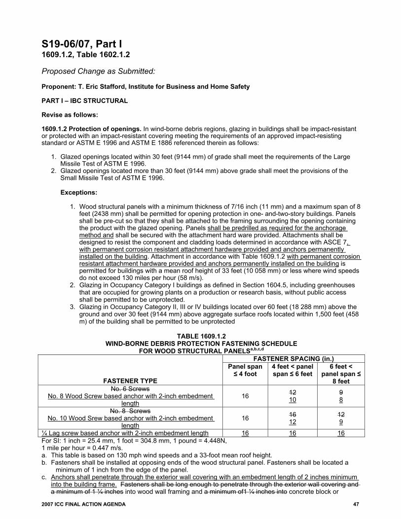
2007 ICC FINAL ACTION AGENDA 47
S19-06/07, Part I 1609.1.2, Table 1602.1.2 Proposed Change as Submitted: Proponent: T. Eric Stafford, Institute for Business and Home Safety PART I – IBC STRUCTURAL Revise as follows: 1609.1.2 Protection of openings. In wind-borne debris regions, glazing in buildings shall be impact-resistant or protected with an impact-resistant covering meeting the requirements of an approved impact-resisting standard or ASTM E 1996 and ASTM E 1886 referenced therein as follows:
1. Glazed openings located within 30 feet (9144 mm) of grade shall meet the requirements of the Large Missile Test of ASTM E 1996.
2. Glazed openings located more than 30 feet (9144 mm) above grade shall meet the provisions of the Small Missile Test of ASTM E 1996.
Exceptions:
1. Wood structural panels with a minimum thickness of 7/16 inch (11 mm) and a maximum span of 8
feet (2438 mm) shall be permitted for opening protection in one- and-two-story buildings. Panels shall be pre-cut so that they shall be attached to the framing surrounding the opening containing the product with the glazed opening. Panels shall be predrilled as required for the anchorage method and shall be secured with the attachment hard ware provided. Attachments shall be designed to resist the component and cladding loads determined in accordance with ASCE 7, with permanent corrosion resistant attachment hardware provided and anchors permanently installed on the building. Attachment in accordance with Table 1609.1.2 with permanent corrosion resistant attachment hardware provided and anchors permanently installed on the building is permitted for buildings with a mean roof height of 33 feet (10 058 mm) or less where wind speeds do not exceed 130 miles per hour (58 m/s).
2. Glazing in Occupancy Category I buildings as defined in Section 1604.5, including greenhouses that are occupied for growing plants on a production or research basis, without public access shall be permitted to be unprotected.
3. Glazing in Occupancy Category II, III or IV buildings located over 60 feet (18 288 mm) above the ground and over 30 feet (9144 mm) above aggregate surface roofs located within 1,500 feet (458 m) of the building shall be permitted to be unprotected
TABLE 1609.1.2
WIND-BORNE DEBRIS PROTECTION FASTENING SCHEDULE FOR WOOD STRUCTURAL PANELSa,b,c,d
FASTENER SPACING (in.)
FASTENER TYPE
Panel span ≤ 4 foot
4 feet < panel span ≤ 6 feet
6 feet < panel span ≤
8 feet No. 6 Screws
No. 8 Wood Screw based anchor with 2-inch embedment length
16 12 10
9 8
No. 8 Screws No. 10 Wood Srew based anchor with 2-inch embedment
length 16 16
12 12 9
¼ Lag screw based anchor with 2-inch embedment length 16 16 16 For SI: 1 inch = 25.4 mm, 1 foot = 304.8 mm, 1 pound = 4.448N, 1 mile per hour = 0.447 m/s. a. This table is based on 130 mph wind speeds and a 33-foot mean roof height. b. Fasteners shall be installed at opposing ends of the wood structural panel. Fasteners shall be located a
minimum of 1 inch from the edge of the panel. c. Anchors shall penetrate through the exterior wall covering with an embedment length of 2 inches minimum
into the building frame. Fasteners shall be long enough to penetrate through the exterior wall covering and a minimum of 1 ¼ inches into wood wall framing and a minimum of1 ¼ inches into concrete block or

48 2007 ICC FINAL ACTION AGENDA
concrete., and into steel framing a minimum of 3 exposed threads. Fasteners shall be located a minimum of 2 ½ inches from the edge of concrete block or concrete.
d. Where panels screws are attached to masonry or masonry/stucco, they shall be attached using vibration-resistant anchors having a minimum ultimate withdrawal capacity of 1500 490 pounds.
Reason: The purpose of this code change is primarily to require permanently mounted hardware when using wood structural panel shutters for window protection for new construction. It is our belief that using wood structural panels as window protection in the manner currently prescribed by the code, is basically an emergency option for protection of existing buildings where the homeowner does not have some permanent shutter system in place.
While the code requires the panels to be precut and the attachment hardware provided, there are potentially many logistical problems with homeowners actually installing the panels as required by the code. It’s not clear that the homeowners will be sufficiently instructed on (or remember at a later date) how to attach the panels, in particular using the prescribed minimum spacing. Additionally, it can be extremely cumbersome to attempt to nail a sheet of plywood over a window, particularly on the second story of a building. Additionally, we are concerned about the capacity of nailed connections where the nails are installed in the same hole repeatedly.
This proposed change also increases the minimum required capacity of masonry anchors from 490 lbs to 1500 lbs. Evaluation reports (ICC, NES, and SBCCI) for masonry anchors require a Factor of Safety (FS) of 4.0 if a special inspection is performed on the anchor installation. Without a special inspection, the reports require a FS of 8.0. Based on the load conditions specified, the 490 lb required capacity implies a FS of 2.5. We do not believe that special inspections are or will be performed on these anchors. Therefore, raising the required capacity of the masonry anchors to 1500 lbs provides a FS more in line with the evaluation reports for masonry anchors.
At the time of preparation of this proposal, the Florida Building Commission Structural Technical Advisory Committee unanimously approved this code change for the 2006 glitch amendment cycle. Cost Impact: The code change proposal will increase the cost of construction. Committee Action: Approved as Modified Modify proposal as follows: 1609.1.2 Protection of openings. In wind-borne debris regions, glazing in buildings shall be impact-resistant or protected with an impact-resistant covering meeting the requirements of an approved impact-resisting standard or ASTM E 1996 and ASTM E 1886 referenced therein as follows:
1. Glazed openings located within 30 feet (9144 mm) of grade shall meet the requirements of the Large Missile Test of ASTM E 1996. 2. Glazed openings located more than 30 feet (9144 mm) above grade shall meet the provisions of the Small Missile Test of ASTM E
1996.
Exceptions:
1. Wood structural panels with a minimum thickness of 7/16 inch (11 mm) and a maximum span of 8 feet (2438 mm) shall be permitted for opening protection in one- and-two-story buildings. Panels shall be pre-cut so that they shall be attached to the framing surrounding the opening containing the product with the glazed opening. Panels shall be predrilled as required for the anchorage method and shall be secured with the attachment hard ware provided. Attachments shall be designed to resist the component and cladding loads determined in accordance with ASCE 7, with permanent corrosion resistant attachment hardware provided and anchors permanently installed on the building. Attachment in accordance with Table 1609.1.2 with permanent corrosion resistant attachment hardware provided and anchors permanently installed on the building is permitted for buildings with a mean roof height of 33 45 feet (10 058 mm) or less where wind speeds do not exceed 130 140 miles per hour (58 m/s).
2. Glazing in Occupancy Category I buildings as defined in Section 1604.5, including greenhouses that are occupied for growing plants on a production or research basis, without public access shall be permitted to be unprotected.
3. Glazing in Occupancy Category II, III or IV buildings located over 60 feet (18 288 mm) above the ground and over 30 feet (9144 mm) above aggregate surface roofs located within 1,500 feet (458 m) of the building shall be permitted to be unprotected.
TABLE 1609.1.2
WIND-BORNE DEBRIS PROTECTION FASTENING SCHEDULE FOR WOOD STRUCTURAL PANELSa,b,c,d
FASTENER SPACING (in.)
FASTENER TYPE Panel span 4 foot 4 feet < panel span 6 feet
6 feet < panel span 8 feet
No. 8 Wood Screw based anchor with 2-inch embedment length 16 10 8
No. 10 Wood Screw based anchor with 2-inch embedment length 16 12 9
¼ Lag screw based anchor with 2-inch embedment length 16 16 16
For SI: 1 inch = 25.4 mm, 1 foot = 304.8 mm, 1 pound = 4.448N, 1 mile per hour = 0.447 m/s. a. This table is based on 130 140 mph wind speeds and a 33 45-foot mean roof height. b. Fasteners shall be installed at opposing ends of the wood structural panel. Fasteners shall be located a minimum of 1 inch from
the edge of the panel. c. Anchors shall penetrate through the exterior wall covering with an embedment length of 2 inches minimum into the building frame.
into wood wall framing and concrete block or concrete. Fasteners shall be located a minimum of 2 ½ inches from the edge of concrete block or concrete.
d. Where panels are attached to masonry or masonry/stucco, they shall be attached using vibration-resistant anchors having a minimum ultimate withdrawal capacity of 1500 pounds.

2007 ICC FINAL ACTION AGENDA 49
Committee Reason: The proposal makes clarifications to the prescriptive option for protection of glazed openings and specifically requires permanent anchorage to be provided. The modification extends the wind speed and roof height limits to be consistent with the revised fastener spacing. The word permanent immediately preceeding “corrosion resistant” was also deleted to avoid confusion. Assembly Action: None Individual Consideration Agenda This item is on the agenda for individual consideration because a public comment was submitted. Public Comment: Gary J. Ehrlich, P.E., National Association of Home Builders (NAHB) requests Disapproval for Part I. Commenter=s Reason: The intent of the IBC and IRC is to safeguard health and life safety and protect structures from damage and collapse due to natural hazards and other hazards resulting from the built environment. The intent of the code is not to protect the personal property of owners and the contents of structures from damage. The proponent’s interest in requiring permanent hardware for wood structural panel shutters is mainly to reduce loss of contents and the resulting insurance claims, and therefore is outside the scope of the IBC. A masonry structure in a wind-borne debris region will have a basic wind speed of 110mph or greater. This exceeds the limits per ACI 530 for design using the empirical provisions of the masonry code and an engineered design must be provided. Therefore, per Section 1704.5, the exemption for empirically-designed masonry does not apply and special inspection of the masonry must be provided. Thus, the proponent’s contention that the factor of safety for anchor pullout has to be doubled in the absence of special inspection is not correct, and the current 4.0 factor of safety for masonry anchors is adequate. An increase in the currently specified withdrawal requirements is not justified. The proponent’s changes to the table are not consistent with the values currently shown in Table 603 of the draft ICC standard for hurricane-resistant construction (ICC-600). The proposal would increase the screw sizes to #8 and #10 screws in Table 1609.1.2 and increase the fastener spacing for panels 4-6 feet wide and 6-8 feet wide to 10 inches and 8 inches respectively, for #8 screws. The proponent has not submitted technical justification to the IBC-S committee for this increase. The IBC and ICC-600 should reflect the same values.
Field studies and simulations conducted after the 2004 hurricane season in Florida showed that less than 10% of the structures in typical urban and suburban communities experienced damage at wind speeds of 120mph and lower and in many or the examined areas less than 3%-4% of the buildings were damaged. Additionally cost/benefit studies suggest that even the use of wood structural panels for wind-borne debris protection in areas with wind speeds 120mph or lower is cannot be economically justified in the typical built-up urban and suburban area with a reasonable amount of surrounding tree cover. Thus, to require permanently-installed hardware for one- and two-story buildings, particularly in residential, retail and commercial applications, is not justified. It should be noted the proponent already previously removed the option provided in this section to design a one- or two-story structure as a partially enclosed building in lieu of providing opening protection or impact-resistant glazing. This has already limited the flexibility of engineers and architects in designing low-rise buildings and imposed an additional cost on commercial and residential owners by forcing them to provide impact-resistant glazing except where they were allowed to use wood structural panels. Now the proponent is increasing the requirements of this section again by imposing permanent attachment requirements and increasing the required design capacities. NAHB asks for your support in disapproving the proposal and reversing the committee’s action. Final Action: AS AM AMPC D
S19-06/07, Part II IRC R301.2.1.2, Table R301.2.1.2 Proposed Change as Submitted: Proponent: T. Eric Stafford, Institute for Business and Home Safety PART II – IRC BUILDING/ENERGY Revise as follows: R301.2.1.2 Protection of openings. Windows in buildings located in windborne debris regions shall have glazed openings protected from windborne debris. Glazed opening protection for windborne debris shall meet the requirements of the Large Missile Test of an approved impact resisting standard or ASTM E 1996 and ASTM E 1886 referenced therein.
Exception: Wood structural panels with a minimum thickness of 7/16 inch (11 mm) and a maximum span of 8 feet (2438 mm) shall be permitted for opening protection in one- and-two-story buildings. Panels shall be pre-cut so that they shall be attached to the framing surrounding the opening containing the product with the glazed opening. Panels shall be predrilled as required for the anchorage method and shall be secured with the attachment hard ware provided. Attachments shall be designed to resist the component and cladding loads determined in accordance with either Table R301.2(2) or Section 1609.6.5 of the International Building Code, with permanent corrosion resistant attachment hardware provided and anchors

50 2007 ICC FINAL ACTION AGENDA
permanently installed on the building. Attachment in accordance with Table R301.2.1.2 is permitted for buildings with a mean roof height of 33 feet (10 058 mm) or less where wind speeds do not exceed 130 miles per hour (58 m/s).
TABLE R301.2.1.2
WIND-BORNE DEBRIS PROTECTION FASTENING SCHEDULE FOR WOOD STRUCTURAL PANELSa,b,c,d
FASTENER SPACING (in.)1,2 FASTENER TYPE Panel
span ≤ 4 foot
4 feet < panel span ≤ 6 feet
6 feet < panel span ≤ 8 feet
No. 6 Screws No. 8 Wood Screw based anchor with 2-inch embedment length 16 12
10 9 8
No. 8 Screws No. 10 Wood Srew based anchor with 2-inch embedment length 16 16
12 12 9
¼ Lag screw based anchor with 2-inch embedment length 16 16 16 For SI: 1 inch = 25.4 mm, 1 foot = 304.8 mm, 1 pound = 4.448N, 1 mile per hour = 0.447 m/s. a. This table is based on 130 mph wind speeds and a 33-foot mean roof height. b. Fasteners shall be installed at opposing ends of the wood structural panel. Fasteners shall be located a
minimum of 1 inch from the edge of the panel. c. Anchors shall penetrate through the exterior wall covering with an embedment length of 2 inches minimum
into the building frame. Fasteners shall be long enough to penetrate through the exterior wall covering and a minimum of 1 ¼ inches into wood wall framing and a minimum of1 ¼ inches into concrete block or concrete., and into steel framing a minimum of 3 exposed threads. Fasteners shall be located a minimum of 2 ½ inches from the edge of concrete block or concrete.
d. Where panels screws are attached to masonry or masonry/stucco, they shall be attached using vibration-resistant anchors having a minimum ultimate withdrawal capacity of 1500 490 pounds.
Reason: The purpose of this code change is primarily to require permanently mounted hardware when using wood structural panel shutters for window protection for new construction. It is our belief that using wood structural panels as window protection in the manner currently prescribed by the code, is basically an emergency option for protection of existing buildings where the homeowner does not have some permanent shutter system in place.
While the code requires the panels to be precut and the attachment hardware provided, there are potentially many logistical problems with homeowners actually installing the panels as required by the code. It’s not clear that the homeowners will be sufficiently instructed on (or remember at a later date) how to attach the panels, in particular using the prescribed minimum spacing. Additionally, it can be extremely cumbersome to attempt to nail a sheet of plywood over a window, particularly on the second story of a building. Additionally, we are concerned about the capacity of nailed connections where the nails are installed in the same hole repeatedly.
This proposed change also increases the minimum required capacity of masonry anchors from 490 lbs to 1500 lbs. Evaluation reports (ICC, NES, and SBCCI) for masonry anchors require a Factor of Safety (FS) of 4.0 if a special inspection is performed on the anchor installation. Without a special inspection, the reports require a FS of 8.0. Based on the load conditions specified, the 490 lb required capacity implies a FS of 2.5. We do not believe that special inspections are or will be performed on these anchors. Therefore, raising the required capacity of the masonry anchors to 1500 lbs provides a FS more in line with the evaluation reports for masonry anchors.
At the time of preparation of this proposal, the Florida Building Commission Structural Technical Advisory Committee unanimously approved this code change for the 2006 glitch amendment cycle. Cost Impact: The code change proposal will increase the cost of construction. Committee Action: Disapproved Committee Reason: There was insufficient technical data to support this change. A safety factor of 8 would be excessive. If this proposal were passed it would no longer allow the use of masonry screws. In addition, the increase in cost predicted to be from 33 to 53 percent was not justified. Assembly Action: None Individual Consideration Agenda This item is on the agenda for individual consideration because a public comment was submitted. Public Comment: T. Eric Stafford, Institute for Business and Home Safety, requests Approval as Modified by this public comment for Part II.

2007 ICC FINAL ACTION AGENDA 51
Modify proposal as follows: R301.2.1.2 Protection of openings. Windows in buildings located in wind-borne debris regions shall have glazed openings protected from windborne debris. Glazed opening protection for windborne debris shall meet the requirements of the Large Missile Test of an approved impact resisting standard for ASTM E 1996 and ASTM E 1886 referenced therein.
Exception: Wood structural panels with a minimum thickness of 7/16 inch (11 mm) and a maximum span of 8 feet (2438 mm) shall be permitted for opening protection in one- and-two-story buildings. Panels shall be pre-cut so that they shall be attached to the framing surrounding the opening containing the product with the glazed opening. Panels shall be predrilled as required for the anchorage method and shall be secured with the attachment hard ware provided. Attachments shall be designed to resist the component and cladding loads determined in accordance with either Table R301.2(2) or Section 1609.6.5 of the International Building Code, with permanent corrosion resistant attachment hardware provided and anchors permanently installed on the building. Attachment in accordance with Table R301.2.1.2 with corrosion resistant attachment hardware provided and anchors permanently installed on the building is permitted for buildings with a mean roof height of 45 33 feet (10 058 mm) or less where wind speeds do not exceed 140 130 miles per hour (58 m/s).
TABLE R301.2.1.2
WIND-BORNE DEBRIS PROTECTION FASTENING SCHEDULE FOR WOOD STRUCTURAL PANELSa,b,c,d
FASTENER TYPE FASTENER SPACING (in.)1,2 Panel span ≤
4 foot 4 feet < panel span ≤ 6 feet
6 feet < panel span ≤ 8 feet
No. 8 Wood Screw based anchor with 2-
inch embedment length 16 10 8
No. 10 Wood Srew based anchor with 2-
inch embedment length 16 12 9
¼ Lag screw based anchor with 2-inch embedment length 16 16 16
For SI: 1 inch = 25.4 mm, 1 foot = 304.8 mm, 1 pound = 4.448N, 1 mile per hour = 0.447 m/s. a. This table is based on 140 130 mph wind speeds and a 45 33-foot mean roof height. b. Fasteners shall be installed at opposing ends of the wood structural panel. Fasteners shall be located a minimum of
1 inch from the edge of the panel. c. Anchors shall penetrate through the exterior wall covering with an embedment length of 2 inches minimum into the building frame.
into wood wall framing and concrete block or concrete. Fasteners shall be located a minimum of 2 ½ inches from the edge of concrete block or concrete.
d. Where panels are attached to masonry or masonry/stucco, they shall be attached using vibration-resistant anchors having a minimum ultimate withdrawal capacity of 1500 pounds.
Commenter=s Reason: We are requesting AMPC for S19 Part II. Taking this action will achieve consistency with the action the IBC Structural Committee took on Part I of this code change. The modifications presented above, which increase the upper limit for using the prescriptive fastening table for wood structural panel shutters from 130 mph to 140 mph and 30 ft in height to 45 ft in height, simply reflect the capacity of the connections proposed in the change. It was an oversight on our part for not including these revisions on the initial change. This proposal requires that anchors for wood structural panel be permanently installed on the building. The modification in this Public Comment expands the region over which the prescriptive attachment method may be used which is a significant tool for those expanded areas. The fasteners and spacings prescribed were determined using ASCE 7. We stand by the reasoning submitted with the proposal and urge your support of this proposal as modified by this Public Comment.
The content of this proposal, as modified by this Public Comment, was approved by the Florida Building Commission for inclusion in the 2006 Supplement to the 2004 Florida Building Codes. Final Action: AS AM AMPC D
S30-06/07 1703.6, 2403.1.1 (New) [IEBC 302.1.1 (New)] Proposed Change as Submitted: Proponent: William W. Stewart, FAIA, Chesterfield, MO, representing himself 1. Delete without substitution: 1703.6 Heretofore approved materials. The use of any material already fabricated or of any construction already erected, which conformed to requirements or approvals heretofore in effect, shall be permitted to continue, if not detrimental to life, health or safety to the public. (Renumber subsequent sections)

52 2007 ICC FINAL ACTION AGENDA
2. Add new text as follows: 3403.1.1 (IEBC 302.1.1) Heretofore approved materials. The use of any material already fabricated or of any construction already erected, which conformed to requirements or approvals heretofore in effect, shall be permitted to continue, if not detrimental to life, health or safety to the public. Reason: This section covers all existing materials and belongs in Chapter 34 Existing Structures. Section 1703.6 has been moved, with no changes to Chapter 34. Cost Impact: The code change proposal will not increase the cost of construction. Committee Action: Disapproved Committee Reason: Rather than relocate to Chapter 34, it is felt that the provision for “heretofore approved materials” is appropriate in its current location, since it would apply to work under construction. Assembly Action: None Individual Consideration Agenda This item is on the agenda for individual consideration because a public comment was submitted. Public Comment: William W. Stewart, FAIA, Chesterfield, MO, representing himself, requests Approval as Submitted. Commenter=s Reason: The committee disapproved this change because they felt it would affect materials in buildings under construction. The commentary makes it clear that this section refers to code complying materials in buildings that have been completed. The commentary says, “If a material or system had been approved before the code took effect, it can continue to be used as long as it can be shown that the material or system is not detrimental to the health or safety of the building occupants or the public. In other words the code is not retroactive.” Therefore this section is more appropriately located in Chapter 34 since Chapter 34 addresses existing buildings. Additionally this stipulation is lost in a section entitled Structural Design since it covers all the materials in a building, not just structural materials. Final Action: AS AM AMPC D
S31-06/07 1704.1 Proposed Change as Submitted: Proponent: Philip Brazil, P.E., Reid Middleton, Inc., representing himself Revise as follows: 1704.1 General. Where application is made for construction as described in this section, the owner or the registered design professional in responsible charge acting as the owner’s agent shall employ one or more special inspectors to provide inspections during construction on the types of work listed under Section 1704. The special inspector shall be a qualified person who shall demonstrate competence, to the satisfaction of the building official, for inspection of the particular type of construction or operation requiring special inspection. These inspections are in addition to the inspections specified in Section 109.
Exceptions: 1. Special inspections are not required for work of a minor nature or as warranted by conditions in the
jurisdiction as approved by the building official. 2. Special inspections are not required for building components unless the design involves the practice of
professional engineering or architecture as defined by applicable state statutes and regulations governing the professional registration and certification of engineers or architects.
3. Unless otherwise required by the building official, special inspections are not required for occupancies in Group R-3 as applicable in Section 101.2 and occupancies in Group U that are accessory to a residential occupancy including, but not limited to, those listed in Section 312.1.

2007 ICC FINAL ACTION AGENDA 53
Reason: In the 2003 IBC, there were approximately 45 provisions applicable to “Group R-3 as applicable in Section 101.2.” Section 101.2 requires application of the provisions of the IBC to every building or structure or any appurtenances connected to or attached to such buildings or structures. Detached one- and two-family dwellings and multiple single-family dwellings not more than three stories above grade with a separate means of egress and their accessory structures, however, are required to comply with the IRC. Existing buildings undergoing repair, alteration or additions and changes of occupancy are permitted to comply with the IEBC.
In the 2006 IBC, the phrase, “as applicable in Section 101.2,” has been deleted in virtually all cases except for Exception 3 to Section 1704.1. Currently, Exception 3 exempts Group R-3 occupancies complying with the IRC from the requirements for special inspection in the IBC. If deletion of the phrase, “as applicable in Section 101.2,” in Section 1704.1 were to occur, Group R-3 occupancies complying with the IBC would be exempt from the requirements for special inspection in the IBC.
The proposal deletes the exemption for Group R-3 occupancies. The structural systems of Group R-3 buildings can just as complex and challenging as those of commercial structures. The use of high-strength concrete, structural steel, high-strength bolting, complete-penetration grove welds, engineered masonry, pile foundations and other materials, components and systems that typically receive special inspection in commercial structures are often seen in Group R-3 buildings. In Seismic Design Categories C, D, E and F, engineered seismic-force-resisting systems are also common.
The requirement for special inspection of Group R-3 occupancies in the IBC is warranted and should be retained. Exception 1 to Section 1704.1 will continue to provide the building official with the discretion to exempt work of a minor nature or as warranted by conditions in the jurisdiction from the requirement for special inspection. Cost Impact: The code change proposal will not increase the cost of construction.
Committee Action: Approved as Submitted Committee Reason: Removing the special inspection exemption for Group R-3 is an improvement that is also consistent with action taken in previous code development cycle. Assembly Action: None Individual Consideration Agenda This item is on the agenda for individual consideration because a public comment was submitted. Public Comment: Gary J. Ehrlich, P.E., National Association of Home Builders, requests Disapproval. Commenter=s Reason: This proposal would subject one- and two-family dwellings and other residential occupancies built under the IBC to special inspection, as well as dwellings built mostly under IRC but using certain IBC provisions (seismic, foundations). Traditionally these structures have not been subjected to special inspections. By removing this exemption, one- and two-family dwellings and townhouses (or portions thereof), and other R-3 occupancy structures would be subject to inspection requirements far in excess of those which would be required for similar projects constructed under the IRC.
Among the new inspections a dwelling or residential occupancy would have to undergo are: • Periodic inspections of framing (in lieu of one final framing inspection under the IRC). • Periodic inspections of the MWFRS in high wind regions (per approved proposal S44-06/07). • Periodic inspections of the roof & wall cladding in high wind regions (per approved proposal S45-06/07). • Periodic inspections of masonry construction in all regions, instead of just Seismic Design Category D and above. • Fabricator inspections for floor & roof trusses, structural insulated panels, and other panelized construction (not required under the IRC). • Submission of wind and seismic quality assurance plans certified by a structural engineer registered in the state. • Possible additional site visits by a structural engineer as directed by the building official over and above those actually required by the
conditions of the project (per approved proposal S47-06/07). This proposal substantially increases the cost of residential construction for those dwellings and residential occupancies that fall under the IBC or use portions of the IBC provisions. One- and two-family dwellings historically have not been subject to these inspections. A rough estimate of the minimum cost of additional inspections for a typical project suggests an added cost of $2,000 for the special inspector’s visits, $300 for a registered design professional to provide wind and seismic QA plans, and $1000 for a structural engineer to perform site visits requested by a building official. This burden will be placed on local building departments as well as builders to comply with these additional inspections, and the cost will be passed along to home buyers. NAHB asks for your support in disapproving this proposal and reversing the committee’s action. Final Action: AS AM AMPC D

54 2007 ICC FINAL ACTION AGENDA
S33-06/07 1704.1 Proposed Change as Submitted: Proponent: Maureen Traxler, City of Seattle, representing Washington Association of Building Officials Revise as follows: 1704.1 General. Where application is made for construction as described in this section, the owner or the registered design professional in responsible charge acting as the owner’s agent shall employ one or more special inspectors to provide inspections during construction on the types of work listed under Section 1704. The special inspector shall be a qualified person who shall demonstrate competence, to the satisfaction of the building official, for inspection of the particular type of construction or operation requiring special inspection. These inspections are in addition to the inspections specified in Section 109.
Exceptions:
1. Special inspections are not required for work of a minor nature or as warranted by conditions in the jurisdiction as approved by the building official.
2. Special inspections are not required for building components unless the design involves the practice of professional engineering or architecture as defined by applicable state statutes and regulations governing the professional registration and certification of engineers or architects.
3. Unless otherwise required by the building official, special inspections are not required for occupancies in Group R-3 as applicable in Section 101.2 and occupancies in Group U that are accessory to a residential occupancy including, but not limited to, those listed in Section 312.1.
Reason: The deleted phrase refers to the “Scope” section of the IBC. It limits the use of the exception to those Group R occupancies that are within the scope of the IBC, such as those that are more than three stories or that do not have a separate means of egress. The phrase has been deleted from every other section of the 2006 edition of the IBC. Some dwellings that are subject to the IRC will use the structural provisions of the IBC as a means of complying with the structural provisions of the IRC. For instance, IRC Section R301.2.2.4.1 and Table R602.10.1 limit the height of wood-framed buildings in Seismic Design Category D1 and D2 to two stories. Three-story buildings will still be subject to the IRC, but the seismic design may be done according to the IBC. Those dwellings should be excepted from special inspection, the same as those that are within the scope of the IBC. Cost Impact: The code change proposal will not increase the cost of construction. Committee Action: Disapproved Committee Reason: This proposal was disapproved because the action taken on S31-06/07 was preferred. Assembly Action: None Individual Consideration Agenda This item is on the agenda for individual consideration because a public comment was submitted. Public Comment: Gary Ehrlich, P.E., National Association of Home Builders, requests Approval as Submitted. Commenter=s Reason: This comment is linked to our comment challenging the action on RB31. The proponent’s proposal clarifies that residences which qualify for the IRC but which use IBC provisions should not be subject to special inspections. This makes sense. If specific IBC sections are used for design of a residence, particularly to get a more accurate and cost-effective design, the builder (and by association the homeowner) should not then be penalized by the additional cost of periodic or continuous special inspections which would not be required under the IRC. As for a residence thrown entirely into the IBC due to seismic or wind concerns, it should not be subject to an estimated $2,000 worth of additional inspections on top of the burden of complying with more conservative IBC requirements and the cost of obtaining an engineered design. Final Action: AS AM AMPC D

2007 ICC FINAL ACTION AGENDA 55
S39-06/07
1704.10 Proposed Change as Submitted: Proponent: Paul K. Heilstedt, P.E., representing ICC Code Technology Committee (CTC) Revise as follows: 1704.10 Sprayed fire-resistant materials. Special inspections for sprayed fire-resistant materials applied to structural elements and decks shall be in accordance with Sections 1704.10.1 through 1704.10.5 6 Special inspections shall be based on the fire-resistance design as designated in the approved construction documents. The tests described in this section shall be based on samplings of specific floor, roof and wall assemblies, and structural framing members. Special inspections shall be performed after the rough installation of electrical, sprinkler, mechanical and plumbing systems and suspension for ceiling systems, where applicable. 1704.10.1 Physical and visual tests. The following physical and visual tests are required to demonstrate compliance with the listing and the fire-resistance rating:
1. Condition of substrates. 2. Thickness of application. 3. Density in pounds per cubic foot (kgs per m3). 4. Bond strength -adhesion/cohesion. 5. Condition of finished application.
1704.10.1 1704.10.2 Structural member surface conditions. The surfaces shall be prepared in accordance with the approved fire-resistance design and the approved manufacturer’s written instructions. The prepared surface of structural members to be sprayed shall be inspected before the application of the sprayed fire-resistant material. 1704.10.2 1704.10.3 Application. The substrate shall have a minimum ambient temperature before and after application as specified in the approved manufacturer’s written instructions. The area for application shall be ventilated during and after application as required by the approved manufacturer’s written instructions. 1704.10.3 1704.10.4 Thickness. The average thickness minus two times the standard deviation of the thickness measurements of the sprayed fire-resistant materials applied to structural elements shall not be less than the thickness required by the approved fire-resistant design. Individual measured thickness, which exceeds the thickness specified in a design by 1/4 inch (6.4 mm) or more, shall be recorded as the thickness specified in the design plus 1/4 inch (6.4 mm). For design thicknesses 1 inch (25 mm) or greater, the minimum allowable individual thickness shall be the design thickness minus 1/4 inch (6.4 mm). For design thicknesses less than 1 inch (25 mm), the minimum allowable individual thickness shall be the design thickness minus 25 percent. Thickness shall be determined in accordance with ASTM E 605. Samples of the sprayed fire-resistant materials shall be selected in accordance with Sections 1704.10.3 1704.10.4.1 and 1704.10.3.2 1704.10.4.2. 1704.10.3.1 1704.10.4.1 Floor, roof and wall assemblies. The thickness of the sprayed fire-resistant material applied to floor, roof and wall assemblies shall be determined in accordance with ASTM E 605, taking the average minus two times the standard deviation of the thickness measurements of not less than four measurements for each 1,000 square feet (93m2) of the sprayed area on each floor or part thereof. 1704.10.4.1.1 Flat decks. Thickness measurements shall be taken from a 12 inches (305 mm) square with a minimum of four measurements, symmetrically. 1704.10.4.1.2 Fluted decks. Thickness measurements shall be taken from a 12 inches (305 mm) square with four random, symmetrical measurements within the square, including one each of the following: valley, crest and sides and report as an average. 1704.10.3.2 1704.10.4.2 Structural framing members. The thickness of the sprayed fire-resistant material applied to structural members shall be determined in accordance with ASTM E 605. Thickness testing shall be performed on not less than 25 percent of the structural members on each floor.

56 2007 ICC FINAL ACTION AGENDA
1704.10.4.2.1 Beams. Thickness measurements shall be made at nine locations around the beam at each end of a 12 inches. (305 mm) length. 1704.10.4.2.2 Joists and trusses. Thickness measurements shall be made at seven locations around the joist or truss at each end of a 12 inches (305 mm) length. 1704.10.4.2.3 W-shape columns. Thickness measurements shall be made at 12 locations around the column at each end of a 12inches (305 mm) length. 1704.10.4.2.4 Tube and pipe columns. Thickness measurements shall be made at a minimum of four locations around the column at each end of a 12 inches (305 mm) length. 1704.10.4 1704.10.5 Density. The density of the sprayed fire-resistant material shall not be less than the density specified in the approved fire-resistant design. Density of the sprayed fire-resistant material shall be determined in accordance with ASTM E 605. The test samples for determining the density of the sprayed fire-resistant materials shall be selected as follows:
1. From each floor, roof and wall assembly at the rate of not less than one sample for every 2,500 square feet
(232 m2) or part thereof of the sprayed area in each story. 2. From beams, girders, joists, trusses and columns at the rate of not less than one sample for each type of
structural framing member for each 2,500 square feet (232 m2) of floor area or part thereof in each story. 1704.10.5 1704.10.6 Bond strength. The cohesive/adhesive bond strength of the cured sprayed fire-resistant material applied to structural elements shall not be less than 150 pounds per square foot (psf) (7.18 kN/m2). The cohesive/adhesive bond strength shall be determined in accordance with the field test specified in ASTM E 736 by testing in-place samples of the sprayed fire-resistant material selected in accordance with Sections 1704.10.5.1 and 1704.10.5.2. 1704.10.6.1 through 1704.10.6.3. 1704.10.5.1 1704.10.6.1 Floor, roof and wall assemblies. The test samples for determining the cohesive/adhesive bond strength of the sprayed fire-resistant materials shall be selected from each floor, roof and wall assembly at the rate of not less than one sample for every 10,000 2,500 square feet (929 232 m2) or part thereof of the sprayed area in each story. 1704.10.5.2 1704.10.6.2 Structural framing members. The test samples for determining the cohesive/adhesive bond strength of the sprayed fire-resistant materials shall be selected from beams, girders, joists, trusses and columns at the rate of not less than one sample for each type of structural framing member for each 10,000 2,500 square feet (929 232 m2) of floor area or part thereof in each story. 1704.10.6.3 Primer, paint and encapsulant bond tests. Bond tests to qualify a primer, paint or encapsulant shall be conducted only when the fire-resistive coating is applied to a primed, painted or encapsulated surface for which acceptable bond-strength performance between these coatings and the fire resistive material has not been measured. A bonding agent approved by the SFRM manufacturer shall to be applied to a primed, painted or encapsulated surface where the bond strengths are found to be below minimum required values. Reason: The ICC Board established the ICC Code Technology Committee (CTC) as the venue to discuss contemporary code issues in a committee setting which provides the necessary time and flexibility to allow for full participation and input by any interested party. The code issues are assigned to the CTC by the ICC Board as “areas of study”. Information on the CTC, including: meeting agendas; minutes; reports; resource documents; presentations; and all other materials developed in conjunction with the CTC effort can be downloaded from the following website: http://www.iccsafe.org/cs/cc/ctc/index.html Since its inception, the CTC has held six meetings - all open to the public. This proposed change is a result of the CTC’s investigation of the area of study entitled “Review of NIST WTC Recommendations”. The scope of the activity is noted as:
Review the recommendations issued by NIST in its report entitled “Final Report on the Collapse of the World Trade Center Towers”, issued September 2005, for applicability to the building environment as regulated by the I-Codes.
This proposal is intended to address only a portion of NIST recommendation 6. For this specific proposed change, CTC is working in cooperation with the NIBS/MMC Committee to Translate the NIST World Trade Center Investigation Recommendations for the Model Codes. The CTC notes in their investigation that many of the recommendations contained in the NIST report require additional information for the CTC to further investigate. As such, CTC intends to continue to study the other NIST recommendations. NIST Recommendation 6 recommends the development of criteria, test methods and standards: (1) for the in-service performance of sprayed fire-resistance materials (SFRM, also commonly referred to as fireproofing or insulation) used to protect structural components; and (2) to ensure that these materials, as-installed, conform to conditions in tests used to establish the fire resistance rating of components, assemblies, and systems. As noted above, this proposed change does not address all aspects of NIST recommendation #6. This proposed change is limited to the necessary inspection parameters for spray applied fire resistant materials after installation and renovation of mechanical, plumbing, electrical and other similar systems.

2007 ICC FINAL ACTION AGENDA 57
The proposed revisions are intended to coordinate the text of the IBC with the two standards currently referenced in the code- ASTM 605 and ASTM 736, and also AWCI Technical Manual 12-A Standard Practice for the Testing and Inspection of Filed Applied Sprayed Fire-resistive Materials which is a guide and as such, is not referenced in the code. This proposal also as adds sampling criteria for density measurements (proposed Section 1704.10.5) in addition to the current sampling criteria for bond measurements. However, it is noted that there are two significant differences between this proposal and the standards noted. The first is the determination of thickness in proposed Section 1704.10.4 which is not in the standards. By using the standard deviation method, the test samples must fall within a specified range, otherwise, the combination of very thin samples of spray applied coatings with thick samples may lead to the application passing the test when in reality, the thin sections represent an insufficient amount of fire proofing. The second is the sample size. Currently, ASTM E 605 stipulates the 10,000 square foot sample size that is also in the code. Given the critical nature of spray-applied fire proofing, as noted in the NIST report, this sampling size is viewed as too large, resulting in an increased probability of inadequate protection. This proposal uses a value of 2,500 square feet. Recommendation #6 also addresses the in-service performance (criteria for performance and durability such as bond strength) of spray applied fire resistance which requires further substantiation. Bibliography: Interim Report No. 1 of the CTC, Area of Study – Review of NIST WTC Recommendations, March 9, 2006. National Institute of Standards and Technology. Final Report of the National Construction Safety Team on the Collapses of the World Trade Center Towers. United States Government Printing Office: Washington, D.C. September 2005. Cost Impact: The code change proposal will increase the cost of construction due to more frequent sampling of spray applied material. Committee Action: Approved as Modified Modify proposal as follows: 1704.10 Sprayed fire-resistant materials. Special inspections for sprayed fire-resistant materials applied to structural elements and decks shall be in accordance with Sections 1704.10.1 through 1704.10.6 Special inspections shall be based on the fire-resistance design as designated in the approved construction documents. The tests described in this section shall be based on samplings of specific floor, roof and wall assemblies, and structural framing members. Special inspections shall be performed after the rough installation of electrical, sprinkler, mechanical and plumbing systems and suspension for ceiling systems, where applicable. 1704.10.1 Physical and visual tests. The following physical and visual tests are required to demonstrate compliance with the listing and the fire-resistance rating:
1. Condition of substrates. 2. Thickness of application. 3. Density in pounds per cubic foot (kgs per m3). 4. Bond strength -adhesion/cohesion. 5. Condition of finished application.
1704.10.2 Structural member surface conditions. The surfaces shall be prepared in accordance with the approved fire-resistance design and the approved manufacturer’s written instructions. The prepared surface of structural members to be sprayed shall be inspected before the application of the sprayed fire-resistant material. 1704.10.3 Application. The substrate shall have a minimum ambient temperature before and after application as specified in the approved manufacturer’s written instructions. The area for application shall be ventilated during and after application as required by the approved manufacturer’s written instructions. 1704.10.4 Thickness. The average thickness minus two times the standard deviation of the thickness measurements No more than 10 percent of the thickness measurements of the sprayed fire-resistant materials applied to structural elements shall not be less than the thickness required by the approved fire-resistant design but in no case less than the minimum allowable thickness required by Section 1704.10.4.1. Individual measured thickness, which exceeds the thickness specified in a design by 1/4 inch (6.4 mm) or more, shall be recorded as the thickness specified in the design plus 1/4 inch (6.4 mm). 1704.10.4.1 Minimum allowable thickness. For design thicknesses 1 inch (25 mm) or greater, the minimum allowable individual thickness shall be the design thickness minus 1/4 inch (6.4 mm). For design thicknesses less than 1 inch (25 mm), the minimum allowable individual thickness shall be the design thickness minus 25 percent. Thickness shall be determined in accordance with ASTM E 605. Samples of the sprayed fire-resistant materials shall be selected in accordance with Sections 1704.10.4.1 1704.10.4.2 and 1704.10.4.2 1704.10.4.3. 1704.10.4.1 1704.10.4.2 Floor, roof and wall assemblies. The thickness of the sprayed fire-resistant material applied to floor, roof and wall assemblies shall be determined in accordance with ASTM E 605, taking the average minus two times the standard deviation of the thickness measurements of not less than four measurements for each 1,000 square feet (93m2) of the sprayed area on each floor or part thereof. 1704.10.4.1.1 1704.10.4.2.1 Flat decks. Thickness measurements shall be taken from a 12 inches (305 mm) square with a minimum of four measurements, symmetrically. 1704.10.4.1.2 1704.10.4.2.2 Fluted decks. Thickness measurements shall be taken from a 12 inches (305 mm) square with four random, symmetrical measurements within the square, including one each of the following: valley, crest and sides and report as an average. 1704.10.4.2 1704.10.4.3 Structural framing members. The thickness of the sprayed fire-resistant material applied to structural members shall be determined in accordance with ASTM E 605. Thickness testing shall be performed on not less than 25 percent of the structural members on each floor. 1704.10.4.2.1 1704.10.4.3.1 Beams. Thickness measurements shall be made at nine locations around the beam at each end of a 12 inches (305 mm) length.

58 2007 ICC FINAL ACTION AGENDA
1704.10.4.2.2 1704.10.4.3.2 Joists and trusses. Thickness measurements shall be made at seven locations around the joist or truss at each end of a 12 inches (305 mm) length. 1704.10.4.2.3 1704.10.4.3.3 W-shape columns. Thickness measurements shall be made at 12 locations around the column at each end of a 12 inches (305 mm) length. 1704.10.4.2.4 1704.10.4.3.4 Tube and pipe columns. Thickness measurements shall be made at a minimum of four locations around the column at each end of a 12 inches (305 mm) length. 1704.10.5 Density. The density of the sprayed fire-resistant material shall not be less than the density specified in the approved fire-resistant design. Density of the sprayed fire-resistant material shall be determined in accordance with ASTM E 605. The test samples for determining the density of the sprayed fire-resistant materials shall be selected as follows:
1. From each floor, roof and wall assembly at the rate of not less than one sample for every 2,500 square feet (232 m2) or part thereof of the sprayed area in each story.
2. From beams, girders, joists, trusses and columns at the rate of not less than one sample for each type of structural framing member for each 2,500 square feet (232 m2) of floor area or part thereof in each story.
1704.10.6 Bond strength. The cohesive/adhesive bond strength of the cured sprayed fire-resistant material applied to structural elements shall not be less than 150 pounds per square foot (psf) (7.18 kN/m2). The cohesive/adhesive bond strength shall be determined in accordance with the field test specified in ASTM E 736 by testing in-place samples of the sprayed fire-resistant material selected in accordance with Sections 1704.10.6.1 through 1704.10.6.3. 1704.10.6.1 Floor, roof and wall assemblies. The test samples for determining the cohesive/adhesive bond strength of the sprayed fire-resistant materials shall be selected from each floor, roof and wall assembly at the rate of not less than one sample for every 2,500 square feet (232 m2) or part thereof of the sprayed area in each story. 1704.10.6.2 Structural framing members. The test samples for determining the cohesive/adhesive bond strength of the sprayed fire-resistant materials shall be selected from beams, girders, joists, trusses and columns at the rate of not less than one sample for each type of structural framing member for each 2,500 square feet (232 m2) of floor area or part thereof in each story. 1704.10.6.3 Primer, paint and encapsulant bond tests. Bond tests to qualify a primer, paint or encapsulant shall be conducted only when the fire-resistive coating is applied to a primed, painted or encapsulated surface for which acceptable bond-strength performance between these coatings and the fire resistive material has not been measured. A bonding agent approved by the SFRM manufacturer shall to be applied to a primed, painted or encapsulated surface where the bond strengths are found to be below minimum required values. Committee Reason: This proposal provides the details to allow for verification that the sprayed fire-resistant material is properly installed. Given the actions the committee has previously taken to assure that the materials are appropriately applied (FS100-06/07) and that the conditions during the application are appropriate (G68-06/07), the inspection is important to verify installation and to help assure proper performance. The modifications deleted the requirements that the acceptance of the inspection measurements be based upon the “standard deviation.” Since this is intended as a means of field inspection, the connection to “standard deviation” was deleted and replaced by the 10 percent limitation. The intent of both the original and this revised text is to provide a 95 percent confidence level that the installed material exceeds the requirements. The committee did note that Section 1704.10.6 of the proposal does refer to the bond strength of 150 pounds. Based on the action taken with code change G68-06/07 a public comment which directs code users to the new Table 403.15 is needed for the high-rise buildings which require a greater bond strength. Assembly Action: None Individual Consideration Agenda This item is on the agenda for individual consideration because a public comment was submitted. Public Comment: Philip Brazil, P.E., Reid Middleton, Inc, representing himself, requests Approval as Modified by this public comment. Modify proposal as follows: 1704.10 Sprayed fire-resistant materials. Special inspections for sprayed fire-resistant materials applied to floor, roof and wall assemblies and structural elements members and decks shall be in accordance with Sections 1704.10.1 through 1704.10.6. Special inspections shall be based on the fire-resistance design as designated in the approved construction documents. The tests described set forth in this section shall be based on samplings of from specific floor, roof and wall assemblies, and structural framing members. Special inspections shall be performed after the rough installation of electrical, automatic sprinkler, mechanical and plumbing systems and suspension systems for ceilings systems, where applicable.
1704.10.1 Physical and visual tests. The special inspections shall include the following physical and visual tests and observations are required to demonstrate compliance with the listing and the fire-resistance rating:
1. Condition of substrates. 2. Thickness of application. 3. Density in pounds per cubic foot (kgs per m3 kg/m3).

2007 ICC FINAL ACTION AGENDA 59
4. Bond strength-adhesion/cohesion. 5. Condition of finished application.
1704.10.2 Structural member surface conditions. The surfaces shall be prepared in accordance with the approved fire-resistance design and the approved manufacturer’s written instructions of approved manufacturers. The prepared surface of structural members to be sprayed shall be inspected before the application of the sprayed fire-resistant material.
1704.10.3 Application. The substrate shall have a minimum ambient temperature before and after application as specified in the approved manufacturer’s written instructions of approved manufacturers. The area for application shall be ventilated during and after application as required by the approved manufacturer’s written instructions of approved manufacturers.
1704.10.4 Thickness. No more than 10 percent of the thickness measurements of the sprayed fire-resistant materials applied to floor, roof and wall assemblies and structural elements members shall be less than the thickness required by the approved fire-resistant resistance design but in no case less than the minimum allowable thickness required by Section 1704.10.4.1.
1704.10.4.1 Minimum allowable thickness. For design thicknesses 1 inch (25 mm) or greater, the minimum allowable individual thickness shall be the design thickness minus 1/4 inch (6.4 mm). For design thicknesses less than 1 inch (25 mm), the minimum allowable individual thickness shall be the design thickness minus 25 percent. Thickness shall be determined in accordance with ASTM E 605. Samples of the sprayed fire-resistant materials shall be selected in accordance with Sections 1704.10.4.2 and 1704.10.4.3.
1704.10.4.2 Floor, roof and wall assemblies. The thickness of the sprayed fire-resistant material applied to floor, roof and wall assemblies shall be determined in accordance with ASTM E 605, taking making not less than four measurements for each 1,000 square feet (93 m2) of the sprayed area on each floor in each story or part portion thereof.
1704.10.4.2.1 Flat Cellular decks. Thickness measurements shall be taken selected from a square area, 12 inches (305 mm) square with a by 12 inches (305 mm) in size. A minimum of four measurements shall be made, located symmetrically within the square area.
1704.10.4.2.2 Fluted decks. Thickness measurements shall be taken selected from a square area, 12 inches (305 mm) square with by 12 inches (305 mm) in size. A minimum of four random, symmetrical measurements shall be made, located symmetrically within the square area, including one each of the following: valley, crest and sides and report as an average.
1704.10.4.3 Structural framing members. The thickness of the sprayed fire-resistant material applied to structural members shall be determined in accordance with ASTM E 605. Thickness testing shall be performed on not less than 25 percent of the structural members on each floor.
1704.10.4.3.1 Beams and girders. At beams and girders, thickness measurements shall be made at nine locations around the beam or girder at each end of a 12 inches 12-inch (305 mm) length.
1704.10.4.3.2 Joists and trusses. At joists and trusses, thickness measurements shall be made at seven locations around the joist or truss at each end of a 12 inches 12-inch (305 mm) length.
1704.10.4.3.3 W-shape Wide-flanged columns. At wide-flanged columns, thickness measurements shall be made at 12 locations around the column at each end of a 12 inches 12-inch (305 mm) length.
1704.10.4.3.4 Tube Hollow structural section and pipe columns. At hollow structural section and pipe columns, thickness measurements shall be made at a minimum of four locations around the column at each end of a 12 inches 12-inch (305 mm) length. 1704.10.5 Density. The density of the sprayed fire-resistant material shall not be less than the density specified in the approved fire- resistant resistance design. Density of the sprayed fire-resistant material shall be determined in accordance with ASTM E 605. The test samples for determining the density of the sprayed fire-resistant materials shall be selected as follows:
1. From each floor, roof and wall assembly at the rate of not less than one sample for every 2,500 square feet (232 m2) or part
portion thereof of the sprayed area in each story. 2. From beams, girders, joists, trusses and columns at the rate of not less than one sample for each type of structural framing
member for each 2,500 square feet (232 m2) of floor area or part portion thereof in each story.
1704.10.6 Bond strength. The cohesive/adhesive bond strength of the cured sprayed fire-resistant material applied to floor, roof and wall assemblies and structural elements members shall not be less than 150 pounds per square foot (psf) (7.18 kN/m2). The cohesive/adhesive bond strength shall be determined in accordance with the field test specified in ASTM E 736 by testing in-place samples of the sprayed fire-resistant material selected in accordance with Sections 1704.10.6.1 through 1704.10.6.3. 1704.10.6.1 Floor, roof and wall assemblies. The test samples for determining the cohesive/adhesive bond strength of the sprayed fire-resistant materials shall be selected from each floor, roof and wall assembly at the rate of not less than one sample for every 2,500 square feet (232 m2) or part thereof of the sprayed area in each story or portion thereof. 1704.10.6.2 Structural framing members. The test samples for determining the cohesive/adhesive bond strength of the sprayed fire-resistant materials shall be selected from beams, girders, joists, trusses, and columns and other structural members at the rate of not less than one sample for each type of structural framing member for each 2,500 square feet (232 m2) of floor area or part portion thereof in each story. 1704.10.6.3 Primer, paint and encapsulant bond tests. Bond tests to qualify a primer, paint or encapsulant shall be conducted only when the fire-resistive coating sprayed fire-resistant material is applied to a primed, painted or encapsulated surface for which acceptable bond-strength performance between these coatings and the fire resistive resistant material has not been measured determined. A bonding agent approved by the SFRM manufacturer shall to be applied to a primed, painted or encapsulated surface where the bond strengths are found to be below minimum less than required values.
60 2007 ICC FINAL ACTION AGENDA
Commenter=s Reason: The purpose for this public comment is to make editorial revisions to Proposal S38. “Structural elements and decks” in Section 1704.10 and “structural elements” in Sections 1704.10.4 and 1704.10.6 are changed to “floor, roof and wall assemblies and structural members” for consistency with Section 714 on the fire-resistance rating of structural members and for consistency with Sections 1704.10, 1704.10.4.2, 1704.10.3 and 1704.10.6.1 on “floor, roof and wall assemblies.” “Structural framing members” are changed to “structural members” in Sections 1704.10 and 1704.10.6.2 for the same reason. Replacing “decks” with “floor, roof and wall assemblies” is also more comprehensive and takes into account special steel plate shear walls (i.e., Table 12.2-1 of ASCE 7-05). Several other changes to Section 1704.10 are proposed. “Described” is changed to “set forth” to avoid non-mandatory language. “Sprinkler” is changed to “automatic sprinkler” for consistency with the terminology in Section 903 on automatic sprinkler systems. “Suspension for ceiling systems” is changed to “suspension systems for ceilings” for consistency with ASTM C 635 and C 636 on suspension systems for acoustical tile and lay-in panel ceilings, which are referenced in Section 803.9.1.1. In Section 1704.10.1, “physical and visual tests” are replaced with “tests and observations” because Items #1 and #5 of Section 1704.10.1 are not accomplished by tests, but by the observations of the special inspector. In Section 1704.10.4, “fire-resistant design” is changed to “fire-resistance design” for consistency with Item #1 of Section 703.3, “fire-resistance designs documented in approved sources.” In Section 1704.10.4.2, “on each floor” is changed to “in each story” for consistency with Section 1704.10.6.1. In Section 1704.10.4.3.1, “beams” is changed to “beams and girders” for consistency with the use of “beams” and “girders” in Section 1704.10.6.2. In Sections 1704.10.4.2, 1704.10.6.1 and 1704.10.6.2, “part” is changed to “portion” because area, not a structural element, is typically referenced. The proposed revisions to Sections 1704.10.4.2.1, 1704.10.4.2.2 and 1704.10.4.3.1 through 1704.10.4.3.4 are intended to bring technical soundness to the provisions and to employ terms more commonly used by the structural engineering profession for the design of structural steel and by nationally recognized testing laboratories in their listings of fire-resistance-rated designs containing sprayed fire-resistant materials. “Flat deck” is changed to “cellular deck” for consistency with the same term used for fluted steel decks with steel sheet added to form flat bottom surfaces. “Random, symmetrical” is replaced by “symmetrical” because symmetrical measurements are not random, they are intentional. References to the subject of Sections 1704.10.4.3.1 through 1704.10.4.3.4 are added to the text because these sections, as written, rely on the title of each section for their charging language. “Tube columns” are changed to “hollow structural section columns” for consistency with current AISC terminology. The language is revised to consistently “select” measurements from specific areas and “make,” not “take,” the measurements in these areas. “Taking measurements implies sampling whereas measurements (i.e., thickness) are typically nondestructive. In Section 1704.10.4.3.3, “W-shape columns” are changed to “wide-flanged columns” for consistency with Section 714.8.3.2 in Proposal FS100-06/07. Note that W-shaped, M-shaped, S-shaped and HP-shaped” structural steel columns are manufactured. The current AISC Specification (AISC 360-05) typically refers to “I-shaped members” (i.e., Chapter F). The 2005 AISC Steel Construction Manual, however, typically refers to W-shapes, M-shapes, S-shapes and HP-shapes, which are described collectively as “H-shaped” and “I-shaped” (i.e., Scope). Because of this level of detail, relying on “W-shape columns” in Section 1704.10.4.3.3 can lead to considerable confusion that can be avoided by use of the more generic “wide-flanged columns.” Several other changes to Section 1704.10.6.3 are proposed. “Fire-resistive coating” is changed to “sprayed fire-resistant material” for consistency with the other provisions in Section 1704.10. Note that special inspection of mastic and intumescent fire-resistant coatings is specified in Section 1704.11. “Fire-resistive material” is changed to “fire-resistant material,” also for consistency with the other provisions in Section 1704.10. “Measured” is changed to “determined” because it refers to “acceptable bond strength performance,” not the results of tests. Final Action: AS AM AMPC D
S40-06/07 1704.15 Proposed Change as Submitted: Proponent: Tony Crimi, A.C. Consulting Solutions, Inc., representing International Firestop Council 1. Add new text as follows: 1704.15 Fire-resistant penetrations and joints. Special inspections for through penetrations, membrane penetrations, joints, and perimeter fire barrier systems of the types specified in Sections 712.3.1.2, 712.4.1.2, 713.3 and 713.4 respectively shall be in accordance with Sections 1704.15.1 or 1704.15.2. Special inspections shall be based on the fire-resistance design or system as designated in the approved construction documents. 1704.15.1 Fire-resistant penetrations. Protected penetrations in fire-resistance-rated assemblies shall not be concealed from view until inspected and approved. Inspections of fire-resistant penetration systems of the types specified in Sections 712.3.1.2 and 712.4.1.2 shall be conducted by an approved inspection agency in accordance with ASTM E 2174. 1704.15.2 Fire-resistive joints. Protection joints within, or at the perimeter of, fire-resistance-rated assemblies shall not be concealed from view until inspected and approved. Inspection of joints of the types specified in 713.3 and 713.4 shall be conducted by an approved inspection agency in accordance with ASTM E 2393. 2. Add standards to Chapter 35: ASTM
E 2174-04 Standard Practice for On-site Inspection of Installed Fire Stops

2007 ICC FINAL ACTION AGENDA 61
E 2393-04 Standard practice for On-Site Inspection of Installed Fire Resistive Joint Systems and Perimeter Fire Barriers.
Reason: The purpose of this proposal is to add new requirements to the Code designed to standardize and generally improve the level of Inspection of fire resistant penetrations, joints, and perimeter fire barrier systems. The Code already mandates proper installation of penetration firestops and joints to maintain the integrity of vertical and horizontal fire or smoke separations. Addition of these ASTM Consensus Standards identifies effective techniques for the field inspection of these systems, and provides consistent procedures needed to conduct and document the on-site assessment of the installations.
Installation of firestop systems and joints is often conducted by trades who do not have the extensive knowledge or training needed to ensure that these critical life safety systems are installed correctly. The current code relies heavily on Installers, Designers, and Code Officials to verify proper system selection and installation. Section 1704 of the International Building Code® (IBC) provides for special inspection agencies. Under the IBC, final authority for recognition of special inspection agencies rests with the building official having jurisdiction.
Firestop and joint system designs and materials are increasing in number and sophistication. In response to this reality, a standard practice was developed within the ASTM process to allow inspections of through-penetration firestops, joints, and perimeter fire barrier systems to be conducted in a thorough and consistent manner, with standardized report formats, regardless of the Trade or individual conducting the inspection. Part of the impetus for the development of that standard was the recognition that jurisdictions sometimes do not have sufficient resources themselves to ensure that all penetrations and joints are firestopped properly. In any project, the number of joints and penetrations can range from hundreds to a few thousand in a single building. The addition of these new Standards to the Code would provide and identify a means for both large and small building departments to have effective tools to instruct either their own staff or third party inspection agencies on good methodologies for inspection of these important systems. The inclusion of consensus standards would ensure that required inspections are conducted consistently, fairly, and adequately, while also standardizing inspection reports, so that they will be of a uniform high quality.
The proposed code change would provide the code official the option of having a third party (e.g. approved inspection agency) to conduct the inspection of joints and penetrations, while preserving the option to utilize other policies and procedures consistent with the intent of the Code. Cost Impact: The code change proposal will not increase the cost of construction. Analysis: Results of review of the proposed standard(s) will be posted on the ICC website by August 20, 2006. Note: The following analysis was not in the Code Change Proposal book but was published in the “Errata to the 2006/2007 Proposed Changes to the International Codes and Analysis of Proposed Referenced Standards” provided at the code development hearings: Analysis: Review of proposed new standard indicated that, in the opinion of ICC staff, the standard did comply with ICC criteria for referenced standards. Committee Action: Disapproved Committee Reason: The proposal would increase the cost of construction due to the need for special inspection on the penetration and joint systems. The committee was also concerned with the new process of requiring inspection of all fire-resistive penetrations and joints and was concerned that this would then get extended to all assemblies and elements within Chapter 7. Although previous committees apparently had indicated that these types of provisions should go in Chapter 17 with the special inspection items, the current committee stated that specifying the test method does belong in Chapter 7 and that they do not believe that special inspection is needed or should be required. Assembly Action: None Individual Consideration Agenda This item is on the agenda for individual consideration because a public comment was submitted. Public Comment: Gilbert Gonzales, Murray City Corp, representing Utah Chapter, ICC, requests Approval as Modified by this public comment. Modify proposal as follows: 1. Add new text as follows: 1704.15 Fire-resistant penetration and joints. Special inspection for through penetrations, membrane penetrations, joints and perimeter fire barrier systems of the types specified in Sections 712.3.1.2,712.4.1.2,713.3 and 713.4 respectively shall be in accordance with Section 1704.15 or 1704.15.2. Special inspections shall be based on fire-resistance rated design or system as designated in the approved construction documents. 1704.15.1 Fire-resistant penetrations. Protected penetrations in fire-resistance-rated assemblies shall not be concealed from view until inspected and approved. Inspections of fire-resistant penetrations systems of the types specified in Sections 712.3.1.2 and 712.4.1.2 shall be conducted by an inspection agency in accordance with ASTM E 2174

62 2007 ICC FINAL ACTION AGENDA
Exceptions:
1. Buildings less than 4 stories in height. 2. Penetration systems installed by UL or FM certified contractors.
1704.15.2 Fire-resistive joints. Protection of joints within, or at the perimeter of fire-resistance rated assemblies shall not be concealed from view until inspected and approved. Inspection of joints of the types specified in 713.3 and 713.4 shall be conducted by an approved inspection agency in accordance with ASTM E 2393.
Exceptions:
1. Buildings less than 4 stories in height. 2. Joint systems installed by UL or FM certified contractors .
2. Add standards to Chapter 35: ASTM E 2174-04 Standard Practice for On-Site Inspection of Installed Fire Stops. E 2393-04 Standard Practice for On-Site Inspection of Installed Fire Resistive Joint Systems and Perimeter Fire Barriers. Commenter=s Reason: As an inspector on a 1.3 millon sq.ft hospital, installation of firestop systems is often conducted by trades and or contractors who do not have the knowledge or expertise needed to ensure a proper installation. Requiring special inspection or certified contractors to perform the work will result in a proper installation. Final Action: AS AM AMPC D
S42-06/07 1707.7 Proposed Change as Submitted: Proponent: Philip Brazil, P.E., Reid Middleton, Inc., representing himself Revise as follows: 1707.7 Architectural components. Periodic special inspection during the erection and fastening of exterior cladding, interior and exterior nonbearing walls and interior and exterior veneer in structures assigned to Seismic Design Category D, E or F.
Exceptions:
1. Special inspection is not required for architectural components in structures 30 feet (9144 mm) or less in height.
2. Special inspection is not required for cladding and veneer weighing 5 psf (24.5N/m2) or less. 3. Special inspection is not required for interior nonbearing walls weighing 15 psf (73.5 N/m2) or less. 4. Special inspection is not required for exterior cladding and exterior veneer 30 feet (9144 mm) or less in
height above grade. Reason: In Seismic Design Categories, D, E and F, Section 1707.7 specifies periodic special inspection during the erection and fastening of certain types of architectural components provided certain thresholds are reached. Currently, the charging statement specifies special inspection for exterior cladding, interior and exterior nonbearing walls and interior and exterior veneer. Exception 1, however, exempts architectural components, which are not specified in the charging statement. Presumably, referring to architectural components does not imply that Section 1707.7 applies to architectural components other than exterior cladding, interior and exterior nonbearing walls and interior and exterior veneer (i.e., interior cladding). Exception 2 exempts cladding and veneer weighing 5 psf or less from special inspection. Presumably, referring to cladding and veneer does not imply that Section 1707.7 applies to interior cladding. Exception 3 exempts interior nonbearing walls, but not exterior nonbearing walls, weighing 15 psf or less from special inspection. In summary, for all structures more than 30 feet in height, periodic special inspection is required for the erection and fastening of (1) all exterior nonbearing walls, (2) all exterior cladding and interior and exterior veneer weighing more than 5 psf, and (3) all interior nonbearing walls weighing more than 15 psf.
The current provisions create several unintended consequences. For example, at a structure more than 30 feet in height, special inspection is required, for example, at anchored brick masonry veneer supported by a concrete foundation and extending from finish grade to a few feet above grade (i.e., wainscot). For the same structure, special inspection is not required for any exterior cladding, interior veneer or exterior veneer weighing less than 5 psf, or for any interior nonbearing walls weighing less than 15 psf, but it s required for all of the exterior nonbearing walls. Special inspection is also required for all exterior cladding, interior veneer and exterior veneer weighing more than 5 psf, and for all interior nonbearing walls weighing more than 15 psf, no matter how close the component is to the ground surface (exterior cladding and veneer) or to the floor surface (interior veneer and nonbearing walls). The current requirements for periodic special inspection are summarized in the table below.

2007 ICC FINAL ACTION AGENDA 63
Exterior Nonbearing Walls Veneer Cladding Interior Exterior Interior Exterior
Structure ≤ 30’0” No No No No No Structure > 30’0” and Exterior Component ≤ 30’0”:
Component ≤ 5 psf No No No No No 5 psf < Component ≤ 15 psf Yes No Yes Yes Yes Component > 15 psf Yes Yes Yes Yes Yes
Structure > 30’0” and Exterior Component > 30’0”: Component ≤ 5 psf No No No No No 5 psf < Component ≤ 15 psf Yes No Yes Yes Yes Component > 15 psf Yes Yes Yes Yes Yes
The proposed changes will establish thresholds for requiring special inspection that are more consistent with the relative risk posed by exterior cladding, interior and exterior nonbearing walls and interior and exterior veneer in Seismic Design Categories, D, E and F. As modified by the proposal, the requirements for periodic special inspection are summarized in the table below. Differences with the current requirements are highlighted in bold.
Exterior Nonbearing Walls Veneer Cladding Interior Exterior Interior Exterior
Structure ≤ 30’0” No No No No No Structure > 30’0” and Exterior Component ≤ 30’0”:
Component ≤ 5 psf No No No No No 5 psf < Component ≤ 15 psf No No No Yes No Component > 15 psf No Yes Yes Yes No
Structure > 30’0” and Exterior Component > 30’0”: Component ≤ 5 psf No No No No No 5 psf < Component ≤ 15 psf Yes No No Yes Yes Component > 15 psf Yes Yes Yes Yes Yes
Cost Impact: The code change proposal will not increase the cost of construction. Committee Action: Disapproved Committee Reason: The prosed change was disapproved at the request of the proponent who intends to submit a modified proposal. Assembly Action: None Individual Consideration Agenda This item is on the agenda for individual consideration because a public comment was submitted. Public Comment: Philip Brazil, P.E., S.E., Reid Middleton, Inc., representing himself, requests Approval as Modified by this public comment. Replace proposal with the following: 1707.7 Architectural components. Periodic special inspection during the erection and fastening of exterior cladding, interior and exterior nonbearing walls and interior and exterior veneer in structures assigned to Seismic Design Category D, E or F.
Exceptions:
1. Special inspection is not required for architectural components in structures cladding, nonbearing walls and veneer 30 feet (9144 mm) or less in height above grade or walking surface.
2. Special inspection is not required for cladding and veneer weighing 5 psf (24.5N/m2) or less. 3. Special inspection is not required for interior nonbearing walls weighing 15 psf (73.5 N/m2) or less.
Commenter=s Reason: The public comment will align Section 1707.7 with Section 2.3.9 of the NEHRP Recommended Provisions for Seismic Regulations for New Buildings and Other Structures (FEMA 450) and achieve better consistency with Section 11A.1.3.9 of ASCE 7-05. As modified by this public comment, the requirements for periodic special inspection are summarized in the table below. Differences between the public comment and the current proposal are highlighted in bold.

64 2007 ICC FINAL ACTION AGENDA
Exterior Nonbearing Walls Veneer Cladding Interior Exterior Interior Exterior
Structure ≤ 30’0” No No No No No Structure > 30’0” and Exterior Component ≤ 30’0”:
Component ≤ 5 psf No No No No No 5 psf < Component ≤ 15 psf No No No No No Component > 15 psf No No No No No
Structure > 30’0” and Exterior Component > 30’0”: Component ≤ 5 psf No No Yes No No 5 psf < Component ≤ 15 psf Yes No Yes Yes Yes Component > 15 psf Yes Yes Yes Yes Yes
Although the title of Section 1707.7 is “architectural components,” the charging language of Section 1707.7 does not specify architectural components. Rather, it specifies exterior cladding, interior and exterior nonbearing walls and interior and exterior veneer, which are examples of architectural components but are not the only types of architectural components. Architectural components other than exterior cladding, interior and exterior nonbearing walls and interior and exterior veneer are not subject to the requirements of Section 1707.7. Final Action: AS AM AMPC D
S44-06/07 1708 (New) Proposed Change as Submitted: Proponent: Philip Brazil, P.E., Reid Middleton, Inc., representing himself Add new text as follows:
SECTION 1708 SPECIAL INSPECTIONS FOR WIND REQUIREMENTS
1708.1 Special inspections for wind requirements. Special inspections itemized in Sections 1708.2 and 1708.3, unless exempted by the exceptions to Section 1704.1, are required for buildings and structures constructed in the following areas:
1. In wind Exposure Category B, where the 3-second-gust basic wind speed is 120 miles per hour (52.8 m/sec) or greater.
2. In wind Exposure Categories C or D, where the 3-second-gust basic wind speed is 110 mph (49 m/sec) or greater.
1708.2 Structural wood. Continuous special inspection is required during field gluing operations of elements of the main wind-force-resisting system. Periodic special inspection is required for nailing, bolting, anchoring and other fastening of components within the main wind-force-resisting system, including wood shear walls, wood diaphragms, drag struts, braces and hold-downs.
Exception: Special inspection is not required for wood shear walls, shear panels and diaphragms, including nailing, bolting, anchoring and other fastening to other components of the main wind-force-resisting system, where the fastener spacing of the sheathing is more than 4 inches (102 mm) on center.
1708.3 Cold-formed steel framing. Periodic special inspection is required during welding operations of elements of the main wind-force-resisting system. Periodic special inspection is required for screw attachment, bolting, anchoring and other fastening of components within the main wind-force-resisting system, including struts, braces, and hold-downs. (Renumber subsequent sections) Reason: In areas of high seismic risk (i.e., Seismic Design Categories C, D, E and F), the IBC currently requires special inspection of seismic-force-resisting systems in buildings of light-frame construction (wood framing and cold-formed steel framing). The risk addressed by these requirements is equally present in areas of high wind forces and special inspection of main wind-force-resisting systems in

2007 ICC FINAL ACTION AGENDA 65
buildings of light-frame construction is equally warranted. The purpose of this proposal is to establish these requirements in areas of high wind forces. This proposal is, in part, a response to comments made by the proponent during floor discussion of code change proposal S72-04/05 at the 2004/2005 code development hearings in Cincinnati. Cost Impact: The code change proposal will not increase the cost of construction. Committee Action: Approved as Submitted Committee Reason: This code change is consistent with the current wind requirements in the statement of special inspection. It closes the loop and meets the intent of Section 1705.4.2. Assembly Action: None Individual Consideration Agenda This item is on the agenda for individual consideration because a public comment was submitted. Public Comment: David P. Tyree, P.E., C.B.O., American Forest and Paper Association, requests Disapproval. Commenter=s Reason: This proposal requires periodic and continuous special inspection of wood buildings in high wind areas. The proposal was based on the current provisions in the IBC for high seismic. In many areas of the country, these provisions will require special inspection of elements which are considered “conventional” or “ordinary” and are inspected by the building departments as required in Section 109. Furthermore, in those situations where the building departments feel they are not qualified to perform these types of inspection, the building official is authorized to require special inspections per Section 104.4. Final Action: AS AM AMPC D
S45-06/07 1708 (New) Proposed Change as Submitted: Proponent: Philip Brazil, P.E., Reid Middleton, Inc., representing himself Add new text as follows:
SECTION 1708 SPECIAL INSPECTIONS FOR WIND REQUIREMENTS
1708.1 Special inspections for wind requirements. Special inspections itemized in Section 1708.2, unless exempted by the exceptions to Section 1704.1, are required for buildings and structures constructed in the following areas:
1. In wind Exposure Category B, where the 3-second-gust basic wind speed is 120 miles per hour (52.8 m/sec) or greater.
2. In wind Exposure Categories C or D, where the 3-second-gust basic wind speed is 110 mph (49 m/sec) or greater.
1708.2 Wind-resisting components. Periodic special inspection is required for the following systems and components:
1. Roof cladding. 2. Wall cladding.
Reason: In areas of high seismic risk (i.e., Seismic Design Categories C, D, E and F), the IBC currently requires special inspection of seismic-force-resisting systems in buildings of light-frame construction (wood framing and cold-formed steel framing). The risk addressed by these requirements is equally present in areas of high wind forces and special inspection of main wind-force-resisting systems in buildings of light-frame construction is equally warranted. A related proposal addresses main wind-force-resisting systems. This proposal addresses the cladding on buildings and structures in areas of high wind forces. Damage to buildings due to high wind forces often begins with failure of the cladding system, which often exposes the main wind-force-resisting system to damage from wind-driven rain and other forces that the wind-force-resisting system is typically not designed to withstand. Cost Impact: The code change proposal will increase the cost of construction.

66 2007 ICC FINAL ACTION AGENDA
Committee Action: Approved as Submitted Committee Reason: This proposal completes the wind resistance special inspections and is consistent with the approval of S44-06/07. Assembly Action: None Individual Consideration Agenda This item is on the agenda for individual consideration because a public comment was submitted. Public Comment: David P. Tyree, P.E., C.B.O., American Forest and Paper Association, requests Disapproval. Commenter=s Reason: This proposal requires periodic and continuous special inspection of wood buildings in high wind areas. The proposal also requires special inspection of roof and wall cladding. There also appears to be a conflict between S44 and S45, as changes were made in both proposals, but it is not obvious how the conflicts will be resolved in the code. In many areas of the country, these provisions will require special inspection of elements which are considered “conventional” or “ordinary” and are inspected by the building departments as required in Section 109. Furthermore, in those situations where the building departments feel they are not qualified to perform these types of inspection, the building official is authorized to require special inspections per Section 104.4. Final Action: AS AM AMPC D
S53-06/07 1808.2.23.2.1 Proposed Change as Submitted: Proponent: Michael Valley, Magnusson Klemencic Associates, representing Structural Engineers Association of Washington Earthquake Engineering Committee Revise as follows: 1808.2.23.2.1 Design details for piers, piles and grade beams. Piers or piles on Site Class E or F sites, as determined in Section 1613.5.2, shall be designed and constructed to withstand maximum imposed curvatures from earthquake ground motions and structure response. Curvatures shall include free-field soil strains modified for soil-pile-structure interaction coupled with pier or pile deformations induced by lateral pier or pile resistance to structure seismic forces. Where constructed of nonprestressed Cconcrete, such piers or piles on Site Class E or F sites, as determined in Section 1613.5.2, shall be designed and detailed in accordance with Sections 21.4.4.1, 21.4.4.2 and 21.4.4.3 of ACI 318 within seven pile diameters of the pile cap and within seven pile diameters of the interfaces of strata that are hard or stiff and soft to medium stiff clay orstrata that are liquefiable or are composed of soft to medium stiff claystrata.
Exception: Piers or piles that satisfy the following additional detailing requirements shall be deemed to comply with the curvature capacity requirements of this section.
1. For Precast prestressed concrete piles, detailed ing provisions as given in accordance with Section 1809.2.3.2.1 and 1809.2.3.2.2 shall apply.
2. Cast-in-place concrete piles with a minimum longitudinal reinforcement ratio of 0.005 extending throughout the region detailed in accordance with Sections 21.4.4.1, 21.4.4.2 and 21.4.4.3 of ACI 318, but not less than the length required in Section 1810.1.2.2.
Grade beams shall be designed as beams in accordance with ACI 318, Chapter 21. When grade beams
have the capacity to resist the forces from the load combinations in Section 1605.4, they need not conform to ACI 318, Chapter 21. Reason: Revise the scope of these additional pile analysis requirements. Clarify the portions of piles affected. Clarify the exception for precast prestressed piles. Add an exception for prescriptively detailed cast-in-place concrete piles.
Design for “pier or pile moments, shears and lateral deflections” is already required by Section 1808.2.23.1.2, and ductile detailing within three pile diameters of the pile cap is already required by Sections 1809.2.2.2.2 and 1810.1.2.2. The requirements of Section 1808.2.23.2.1, which add to those requirements, are taken from the NEHRP Recommended Provisions and are motivated by concern with

2007 ICC FINAL ACTION AGENDA 67
pile response in soft or liquefiable soils (extended hinging region and kinematic interaction), as indicated in the NEHRP Commentary copied below. Such soils are assigned to Site Class E or F, as indicated in IBC Table 1615.1.1, so the corresponding additional requirements should be scoped accordingly.
At present this section applies to all buildings on piers or piles for all site classes, but that scope is inconsistent with both the rationale for the requirement and the state-of-the-practice. Requiring all geotechnical engineers to address the kinematic interaction issue for all projects will result in a large range of response ranging from nothing to potential recommendations for more expensive foundation types that don’t significantly reduce societal risk.
As indicated in the NEHRP Commentary copied below, properly detailed piles provide the desired performance. For nonprestressed concrete piles, such proper detailing is defined in Sections 21.4.4.1, 21.4.4.2 and 21.4.4.3 of ACI 318. For precast prestressed piles, such proper detailing is defined in Section 1809.2.3.2.2 (which adds to the requirements in 1809.2.3.2.1). The section as modified maintains those detailing requirements and clarifies that this special detailing addresses the requirement related to “maximum imposed curvature.”
The text defining the soil interfaces of concern is revised for clarity based on Section 14.2.7.2.1 of ASCE 7-05. Commentary to the 2003 NEHRP Recommended Provisions Section 7.5.4 [emphasis added]:
Special consideration is required in the design of concrete piles subject to significant bending during earthquake shaking. Bending can become crucial to pile design where portions of the foundation piles are supported in soils such as loose granular materials and/or soft soils that are susceptible to large deformations and/or strength degradation. Severe pile bending problems may result from various combinations of soil conditions during strong ground shaking, for example:
1. Soil settlement at the pile-cap interface either from consolidation of soft soil prior to the earthquake or from soil compaction during the earthquake can create a free-standing short column adjacent to the pile cap.
2. Large deformations and/or reduction in strength resulting from liquefaction of loose granular materials can cause bending and/or conditions of free-standing columns.
3. Large deformations in soft soils can cause varying degrees of pile bending. The degree of pile bending will depend upon thickness and strength of the soft soil layer(s) and/or the properties of the soft/stiff soil interface(s).
Such conditions can produce shears and/or curvatures in piles that may exceed the bending capacity of conventionally designed piles and result in severe damage. …
The desired foundation performance can be accomplished by proper selection and detailing of the pile foundation system. Such design should accommodate bending from both reaction to the building’s inertial loads and those induced by the motions of the soils themselves. Examples of designs of concrete piles include: 1. Use of a heavy spiral reinforcement and 2. Use of exterior steel liners to confine the concrete in the zones with large curvatures or shear stresses.
These provide proper confinement to ensure adequate ductility and maintenance of functionality of the confined core of the pile during and after the earthquake.
Precast prestressed concrete piles are exempted from the concrete special moment frame detailing requirements adapted for concrete piles since these provisions were never intended for slender precast prestressed concrete elements and will result in unbuildable piles. Piles with substantially less confinement reinforcement than required by ACI 318 equation 10-6 have been proven through cyclic testing to have adequate performance (Park and Hoat Joen, 1990).
Cost Impact: The code change proposal will not increase the cost of construction. Committee Action: Approved as Submitted Committee Reason: This proposal provides guidance to engineers on the additional pile analysis requirements for structures that are classified as Seismic Design Category D, E or F. Assembly Action: None Individual Consideration Agenda This item is on the agenda for individual consideration because a public comment was submitted. Public Comment: John Diebold, Structural Engineers Association of California, SEAOC Seismology Committee, requests Approval as Modified by this public comment. Modify proposal as follows: 1808.2.23.2.1 Design details for piers, piles and grade beams. Piers or piles on Site Class E or F sites, as determined in Section 1613.5.2, shall be designed and constructed to withstand maximum imposed curvatures from earthquake ground motions and structure response. Curvatures shall include free-field soil strains modified for soil-pile-structure interaction coupled with pier or pile deformations induced by lateral pier or pile resistance to structure seismic forces. Where constructed of nonprestressed concrete such piers or piles shall be designed and detailed in accordance with Sections 21.4.4.1, 21.4.4.2 and 21.4.4.3 of ACI 318 within seven pile diameters of the pile cap and within seven pile diameters of the interfaces of strata that are hard or stiff and strata that are liquefiable or are composed of soft to medium stiff clay.

68 2007 ICC FINAL ACTION AGENDA
Exception: Piers or piles that satisfy the following additional detailing requirements shall be deemed to comply with the curvature capacity requirements of this section.
1. Precast prestressed concrete piles detailed in accordance with Section 1809.2.3.2.2. 2. Cast-in-place concrete piles with a minimum longitudinal reinforcement ratio of 0.005 extending the full length of the pile
extending throughout the region and detailed in accordance with Sections 21.4.4.1, 21.4.4.2 and 21.4.4.3 of ACI 318 as required by this section., but not less than the length required in Section 1810.1.2.2.
Where constructed of nonprestressed concrete such piers or piles shall be designed and detailed in accordance with Sections
21.4.4.1, 21.4.4.2 and 21.4.4.3 of ACI 318 within seven pile diameters of the pile cap and within seven pile diameters of the interfaces of strata that are hard or stiff and strata that are liquefiable or are composed of soft to medium stiff clay. Commenter=s Reason: The Structural Engineers Association of California Seismology Committee agrees with the intent and spirit of the original proposal.
There are two points of concern that our Structural Engineers of California Seismology Committee believes are valid and need to be addressed as indicated in this modification. They are as follows: 1. The 0.005 longitudinal reinforcing ratio for the pile should be for the full length of the pile and not just for the "area detailed". The
reason for this is that without the curvature analysis, the actual required flexural length of the pile has not been determined - so the point where this reinforcing could be reduced is unclear. Placing this reinforcement throughout the pile length compensates for what is unknown. The original proposal does not adequately address this. See Further Elaboration of Point #1 below for further discussion.
2. The closer tie spacing requirement for the 7 pile diameters above and below the interface and below the pile cap should be stated such that it clearly also applies to Exception 2. Otherwise, our concern is that the way the original S53 proposal reads could be misinterpreted to mean that the exception takes away the requirement for the stricter tie spacing within the 7 pile diameter distance of the interface and the bottom of the pile cap.
This can be clarified by moving the following phrase after the exception, or placing the exception prior to this phrase: "Where constructed of nonprestressed concrete, such piers or piles shall be designed and detailed in accordance with Sections 21.4.4.1, 21.4.4.2 and 21.4.4.3 of ACI 318 within seven pile diameters of the pile cap and within seven pile diameters of the interfaces of strata that are hard or stiff and strata that are liquefiable or are composed of soft to medium stiff clay." Further Elaboration of Point #1: The exception is intended to provide equivalence to the curvature analysis and curvature capacity requirements. Therefore, the intent to require the .005 reinforcement the entire length of the pile is to address the imposed curvatures, which would have been calculated by the kinematic analysis but is being "waived" by this exception. The original proposal points to extending the longitudinal reinforcing a length that "should be not less than the length required in Section 1810.1.2.2". The original proposal does not provide clarity regarding the length of the vertical reinforcing, nor does it provide any added detailing requirement to justify not performing the curvature analysis. 1810.1.2.2 requires that the "flexural length" be known - which could be determinable for Site Class D, but requires the more complicated kinematic analysis for multiple strata associated with Site Class E or F. Because we are attempting to address a complex field condition where there are differing soil strata that will impose curvatures on the pile, it makes sense to provide this minimum amount (.005) of "flexural" longitudinal reinforcement to provide a level of structural integrity. It should run the full length of the pile, because the analysis to determine the extent of the curvature has not been done per the exception. Final Action: AS AM AMPC D
S56-06/07 1908.1.16 Proposed Change as Submitted: Proponent: John F. Silva, SE, Hilti, Inc. Revise as follows: 1908.1.16 ACI 318, Section D.3.3. Modify ACI 318, Sections D.3.3.2 through D.3.3.5 to read as follows: D.3.3.2 – In structures assigned to Seismic Design Category C, D, E or F, post-installed anchors for use under D.2.3 shall have passed the Simulated Seismic Tests of ACI 355.2. D.3.3.3 – In structures assigned to Seismic Design Category C, D, E or F, the design strength of anchors shall be taken as 0.75ϕNn and 0.75ϕVn, where ϕ is given in D.4.4 or D.4.5, and Nn and Vn are determined in accordance with D.4.1. D.3.3.4 – In structures assigned to Seismic Design Category C, D, E or F, anchors shall be designed to be governed by tensile or shear strength of a ductile steel element, unless D.3.3.5 is satisfied.

2007 ICC FINAL ACTION AGENDA 69
Exception: Anchors in concrete designed to support non-structural components in accordance with ASCE 7 Section 13.4.2 need not satisfy Section D.3.3.4.
D.3.3.5 – Instead of D.3.3.4, the attachment that the anchor is connecting to the structure shall be designed so that the attachment will undergo ductile yielding at a load level corresponding to anchor forces not greater that the design strength of anchor specified in D.3.3.3, or the minimum design strength of the anchor shall be at least 2.5 times the factored forces transmitted by the attachment.
Exception: Anchors in concrete designed to support non-structural components in accordance with ASCE 7 Section 13.4.2 need not satisfy Section D.3.3.5.
Reason: The purpose of the proposed code change is to correct an error that arises from the multiple provisions that address the design of non-ductile anchors.
This code change proposal corrects an inadvertent problem in coordination between the NEHRP Provisions and the ACI code in anchorage force requirements for the seismic design of nonstructural components. Currently, both ASCE 7 Section 13.4.2, which regulates the design of non-structural components for earthquake loading, and Section 1908.1.16, which addresses the design of anchors in concrete, impose additional load factors on anchors in SDC C and above. Increases for non-ductile anchorage forces are provided in ASCE 7-05 Section 13.4.2 and the changes to ACI 318-05 provided in IBC Section 1908.1.16 provide similar increases. It was never intended that non-ductile anchor force increase factors for nonstructural components be applied twice. Cost Impact: This change is expected to reduce the cost of anchorage of nonstructural components attached to concrete. Committee Action: Approved as Submitted Committee Reason: This code change adds exceptions to correct a duplication in the penalty on non-ductile anchors supporting non-structural components. Assembly Action: None Individual Consideration Agenda This item is on the agenda for individual consideration because public comments were submitted. Public Comment 1: Ranjit L. Bandyopadhyay, Washington Savannah River Co., representing himself, requests Approval as Modified by this public comment. Modify proposal as follows: D.3.3.4 – In structures assigned to Seismic Design Category C, D, E or F, anchors shall be designed to be governed by tensile or shear strength of a ductile steel element, unless D.3.3.5 is satisfied.
Exception: Anchors in concrete designed to support non-structural components in accordance with ASCE 7 Section 13.4.2 need not satisfy Section D.3.3.4.
D.3.3.5 – Instead of D.3.3.4, the attachment that the anchor is connecting to the structure shall be designed so that the attachment will undergo ductile yielding at a load level corresponding to anchor forces not greater that the design strength of anchor specified in D.3.3.3, or the minimum design strength of the anchor shall be at least 2.5 times the factored forces transmitted by the attachment.
Exception: Anchors in concrete designed to support non-structural components in accordance with ASCE 7 Section 13.4.2 need not satisfy Section D.3.3.5. provided that the 1.3 component force increase shall not apply and the value of Rp used to determine the forces in the connected part shall not exceed 4.
Commenter=s Reason: Anchorage design generally follows ACI procedures, ACI 318 or ACI 349. As a member of ACI 349 & 355 Committee, we are trying to align the procedures for design. The exceptions provided in the above proposal make it more confusing. I believe the modifications provided by me align IBC, ACI 318 & ACI 349. The specific reasons are given below. (D.3.3.4) Anchorages in concrete shall preferably be ductile. If ductile anchorages cannot be achieved, non-ductile anchorages are allowed with reduced allowables.
(D.3.3.5) The reasons provided for Exception (refer S56-06/07) are inadequate, and may lead to unconservatism. The Codes always preferred ductile anchors, with a knock down factor (kdf) for non-ductile anchors. In UBC (refer 1997 version), this
was achieved by restricting Rp factor to 1.5 (refer section 1632.2 0f UBC-’97). If the anchorage was of non-ductile material, Rp was further restricted to 1.0. The idea was that as the equipment is undergoing non-linear deformation, the anchorages must be intact, so anchorages were designed for higher forces by limiting Rp values. ASCE applied 1.3 modification factor on demand and additionally restricted Rp value.
ACI 349-01(and now ‘06) allowed non-ductile anchors with a kdf of 0.6. Recent amendments on ACI 318-05 (to be included in ’08 code) specifies a kdf of 0.4. It is understood that applying 1.3 modification factor on demand as per ASCE puts double penalty on the anchor. As such the more conservative kdf value of 0.4 is retained, and ASCE factor 1.3 on demand not applied. However, it is still prudent to limit Rp value, so that the component may deform without any prejudice to the anchor, as explained below.

70 2007 ICC FINAL ACTION AGENDA
ASCE 7-05, when published, still restricted the Rp value to 1.5, even though Rp and ap values both have gone up from the ’97 UBC values. However, the Errata posted on September 15, 2006, puts an “or” between ‘a’, ‘b’ and ‘c’ in the second part of Section 13.4.2, and completely changes the original intent. It seems to imply that if the anchor is prequalified for seismic applications per ACI 355.2, Rp values do not matter, we can go to as high Rp values as the Code allows. But the misconception lies in the fact that passing ACI 355.2 test only implies that it is suitable for use in seismic application, nothing to do with non-ductile anchors. I still think that original intent before the Errata was right, and there must be a limit on Rp values. Considering that ap values have gone up with Rp values, it is proposed to limit the Rp value to 4. Alternatively, to be more precise, a limit on the value of (ap/Rp) may be applied. Public Comment 2: Jagadish R. Joshi, Washington Savannah River Co., representing himself, requests Approval as Modified by this public comment. Modify proposal as follows: D.3.3.4 – In structures assigned to Seismic Design Category C, D, E or F, anchors shall be designed to be governed by tensile or shear strength of a ductile steel element, unless D.3.3.5 is satisfied.
Exception: Anchors in concrete designed to support non-structural components in accordance with ASCE 7 Section 13.4.2 need not satisfy Section D.3.3.4.
D.3.3.5 – Instead of D.3.3.4, the attachment that the anchor is connecting to the structure shall be designed so that the attachment will undergo ductile yielding at a load level corresponding to anchor forces not greater that the design strength of anchor specified in D.3.3.3, or the minimum design strength of the anchor shall be at least 2.5 times the factored forces transmitted by the attachment.
Exception: Anchors in concrete designed to support non-structural components in accordance with ASCE 7 Section 13.4.2 need not satisfy Section D.3.3.5. shall be designed so that the attachment will undergo ductile yielding at a load level corresponding to anchor forces not greater than the design strength of anchor specified in D.3.3.3, or the minimum design strength of the anchor shall be at least 2 times the factored forces transmitted by the attachment.
Commenter’s Reason: (D.3.3.4): Anchorage to concrete is preferred to be ductile, for structures and for nonstructural components. Non-ductile anchorage for both is permitted per D.3.3.5. (D.3.3.5) The reason given in the proposed change is misleading, inappropriate and inadequate. Two provisions related to the seismic load on anchorage are stated to be un-coordinated: Section 1908.1.16 of IBC and Section 13.4.2 of ASCE 7-05. It implies that the “increase factors” in these provisions are duplicative or “equal”. They are not. Section 1908.1.16 provides an “increase factor” of 2.5 for non-ductile anchors. Section 13.4.2 of ASCE 7 provides a factor of 1.3 for all (ductile and non-ductile) anchorage to concrete for nonstructural components. Having determined that both increase factors need not be applied for nonstructural components, it is appropriate to retain the higher of the two, not the lower. That is, effectively the factor of 2.5 should be retained. The easiest and the most logical approach for nonstructural components would be to delete the 1.3 factor for nonstructural components. However IBC Section 1908.1.16 under consideration in the proposed change deals only with modifications to provisions of ACI 318, and not of ASCE 7. Thus what would be relevant to do is to reduce the increase factor of 2.5 such that when multiplied by 1.3, it results into 2.5. That is, change the increase factor to (2.5/1.3 =) 1.923. This is rounded to 2.0 for convenience in the proposed modification above. IBC would be justified in making the proposed change only if it could demonstrate that the safety margin with the proposed change, i.e., deletion of the 2.5 factor, is adequate. I believe such an activity is primarily under the jurisdiction of the ACI (and may be, NEHRP or ASCE) committees. Indeed the reason given in the proposed change claims no such comparison bases with respect to anchorage test data. The proposed modification retains, in effect, the 2.5 increase factor for non-ductility of anchorage of nonstructural components but deletes the 1.3 factor. It should be noted that a September 15, 2006 “errata” on ASCE 7 Section 13.4.2, referenced in the proposed change, has removed the previous limit of 1.5 on RP for non-ductile anchorage (that meets requirement of D.3.3.2 per IBC Section 1908.1.16) for nonstructural components, resulting into potential significant reduction of design forces for some nonstructural components. If IBC chooses to demonstrate that desired safety margins for anchorage of nonstructural components are maintained with respect to the test data on anchorage, it would have to consider effects of the IBC proposed change to 1908.1.16 along with the ASCE 7 Section 13.4.2 “errata”. It would be prudent for the IBC not to add any more relief than that provided in ASCE 7 errata on Section 13.4.2, for non-ductile anchorage of nonstructural components unless it can demonstrate that certain safety margins are maintained with these IBC and ASCE 7 changes with respect to the test data on anchorage to concrete. There is no change arising from this modification in the Cost Impact given in the Proposed Change S57-06/07. Final Action: AS AM AMPC D
S58-06/07 2102, 2104.3 through 2104.4.3, Table 1704.5.1, Table 1704.5.3 Proposed Change as Submitted:

2007 ICC FINAL ACTION AGENDA 71
Proponents: Phillip Samblanet, The Masonry Society Jason J. Thompson, Masonry Alliance for Codes and Standards 1. Delete without substitution:
SECTION 2102 DEFINITIONS AND NOTATIONS
MEAN DAILY TEMPERATURE. The average daily temperature of temperature extremes predicted by a local weather bureau for the next 24 hours. 2104.3 Cold weather construction. The cold weather construction provisions of ACI 530.1/ASCE 6/TMS 602, Article 1.8 C, or the following procedures shall be implemented when either the ambient temperature falls below 40°F (4°C) or the temperature of masonry units is below 40°F (4°C). 2104.3.1 Preparation.
1. Temperatures of masonry units shall not be less than 20°F (-7°C) when laid in the masonry. Masonry units containing frozen moisture, visible ice or snow on their surface shall not be laid.
2. Visible ice and snow shall be removed from the top surface of existing foundations and masonry to receive new construction. These surfaces shall be heated to above freezing, using methods that do not result in damage.
2104.3.2 Construction. The following requirements shall apply to work in progress and shall be based on ambient temperature. 2104.3.2.1Construction requirements for temperatures between 40°F (4°C) and 32°F (0°C). The following construction requirements shall be met when the ambient temperature is between 40°F (4°C) and 32°F (0°C):
1. Glass unit masonry shall not be laid. 2. Water and aggregates used in mortar and grout shall not be heated above 140°F (60°C). 3. Mortar sand or mixing water shall be heated to produce mortar temperatures between 40°F (4°C) and
120°F (49°C) at the time of mixing. When water and aggregates for grout are below 32°F(0°C), they shall be heated.
2104.3.2.2 Construction requirements for temperatures between 32°F (0°C) and 25°F (-4°C). The requirements of Section 2104.3.2.1 and the following construction requirements shall be met when the ambient temperature is between 32°F (0°C) and 25°F (-4°C):
1. The mortar temperature shall be maintained above freezing until used in masonry. 2. Aggregates and mixing water for grout shall be heated to produce grout temperature between 70°F
(21°C) and 120°F (49°C) at the time of mixing. Grout temperature shall be maintained above 70°F (21°C) at the time of grout placement.
3. Heat AAC masonry units to a minimum temperature of 40°F (4°C) before installing thin-bed mortar.
2104.3.2.3 Construction requirements for temperatures between 25°F (-4°C) and 20°F (-7°C). The requirements of Sections 2104.3.2.1 and 2104.3.2.2 and the following construction requirements shall be met when the ambient temperature is between 25°F (-4°C) and 20°F (-7°C):
1. Masonry surfaces under construction shall be heated to 40°F (4°C). 2. Wind breaks or enclosures shall be provided when the wind velocity exceeds 15 miles per hour (mph)
(24 km/h). 3. Prior to grouting, masonry shall be heated to a minimum of 40°F (4°C).
2104.3.2.4 Construction requirements for temperatures below 20°F (-7°C). The requirements of Sections 2104.3.2.1, 2104.3.2.2 and 2104.3.2.3 and the following construction requirement shall be met when the ambient temperature is below 20°F (-7°C): Enclosures and auxiliary heat shall be provided to maintain air temperature within the enclosure to above 32°F (0°C).

72 2007 ICC FINAL ACTION AGENDA
2104.3.3 Protection. The requirements of this section and Sections 2104.3.3.1 through 2104.3.3.5 apply after the masonry is placed and shall be based on anticipated minimum daily temperature for grouted masonry and anticipated mean daily temperature for ungrouted masonry. 2104.3.3.1 Glass unit masonry. The temperature of glass unit masonry shall be maintained above 40°F (4°C) for 48 hours after construction. 2104.3.3.2 AAC masonry. The temperature of AAC masonry shall be maintained above 32°F (0°C) for the first 4 hours after thin-bed mortar application. 2104.3.3.3 Protection requirements for temperatures between 40°F (4°C) and 25°F (-4°C). When the temperature is between 40°F (4°C) and 25°F (-4°C), newly constructed masonry shall be covered with a weather-resistive membrane for 24 hours after being completed. 2104.3.3.4 Protection requirements for temperatures between 25°F (-4°C) and 20°F (-7°C). When the temperature is between 25°F (-4°C) and 20°F (-7°C), newly constructed masonry shall be completely covered with weather-resistive insulating blankets, or equal protection, for 24 hours after being completed. The time period shall be extended to 48 hours for grouted masonry, unless the only cement in the grout is Type III portland cement. 2104.3.3.5 Protection requirements for temperatures below20°F (-7°C). When the temperature is below 20°F (-7°C), newly constructed masonry shall be maintained at a temperature above 32°F (0°C) for at least 24 hours after being completed by using heated enclosures, electric heating blankets, infrared lamps or other acceptable methods. The time period shall be extended to 48 hours for grouted masonry, unless the only cement in the grout is Type III portland cement. 2104.4 Hot weather construction. The hot weather construction provisions of ACI 530.1/ASCE 6/TMS 602, Article 1.8 D, or the following procedures shall be implemented when the temperature or the temperature and wind-velocity limits of this section are exceeded. 2104.4.1 Preparation. The following requirements shall be met prior to conducting masonry work. 2104.4.1.1 Temperature. When the ambient temperature exceeds 100°F (38°C), or exceeds 90°F (32°C) with a wind velocity greater than 8 mph (3.5 m/s):
1. Necessary conditions and equipment shall be provided to produce mortar having a temperature below 120°F (49°C).
2. Sand piles shall be maintained in a damp, loose condition.
2104.4.1.2 Special conditions. When the ambient temperature exceeds 115°F (46°C), or 105°F (40°C) with a wind velocity greater than 8 mph (3.5 m/s), the requirements of Section 2104.4.1.1 shall be implemented, and materials and mixing equipment shall be shaded from direct sunlight. 2104.4.2 Construction. The following requirements shall be met while masonry work is in progress. 2104.4.2.1 Temperature. When the ambient temperature exceeds 100°F (38°C), or exceeds 90°F (32°C) with a wind velocity greater than 8 mph (3.5 m/s):
1. The temperature of mortar and grout shall be maintained below 120°F (49°C). 2. Mixers, mortar transport containers and mortar boards shall be flushed with cool water before they come
into contact with mortar ingredients or mortar. 3. Mortar consistency shall be maintained by retempering with cool water. 4. Mortar shall be used within 2 hours of initial mixing. 5. Thin-bed mortar shall be spread no more than 4 feet (1219 mm) ahead of AAC masonry units. 6. AAC masonry units shall be placed within one minute after spreading thin-bed mortar.
2104.4.2.2 Special conditions. When the ambient temperature exceeds 115°F (46°C), or exceeds 105°F (40°C) with a wind velocity greater than 8 mph (3.5 m/s), the requirements of Section 2104.4.2.1 shall be implemented and cool mixing water shall be used for mortar and grout. The use of ice shall be permitted in the mixing water prior to use. Ice shall not be permitted in the mixing water when added to the other mortar or grout materials.

2007 ICC FINAL ACTION AGENDA 73
2104.4.3 Protection. When the mean daily temperature exceeds 100°F (38°C) or exceeds 90°F (32°C) with a wind velocity greater than 8 mph (3.5 m/s), newly constructed masonry shall be fog sprayed until damp at least three times a day until the masonry is three days old. (Renumber subsequent sections) 2. Revise table as follows:
TABLE 1704.5.1 LEVEL 1 SPECIAL INSPECTION
FREQUENCY OF
INSPECTION
REFERENCE FOR CRITERIA
INSPECTION TASK Continuous during task
listed
Periodically during task
listed
IBC
Section
ACI 530/ASCE5/TMS
402a
ACI 530.1/ASCE 6/TMS 602a
2. The inspection program shall verify: e. Protection of masonry during cold
weather (temperature below 40°F) or hot weather (temperature above 90°F).
Sec. 2104.3, 2104.4
Art. 1.8C, 1.8D
(Portions of table not shown do not change)
TABLE 1704.5.3 LEVEL 2 SPECIAL INSPECTION
FREQUENCY OF
INSPECTION
REFERENCE FOR CRITERIA
INSPECTION TASK Continuous during task
listed
Periodically during task
listed
IBC
Section
ACI 530/ASCE5/TMS
402a
ACI 530.1/ASCE 6/TMS 602a
2. The inspection program shall verify: e. Protection of masonry during cold
weather (temperature below 40°F) or hot weather (temperature above 90°F).
Sec. 2104.3, 2104.4
Art. 1.8C, 1.8D
(Portions of table not shown do not change) Reason: This change removes transcribed provisions from the referenced standard ACI 530.1.1/ASCE 6/TMS 602, thus simplifying the IBC and avoiding the chance that the provisions in the IBC and the referenced standard vary unnecessarily.
Since the development of the IBC, the sponsoring organizations of the ACI 530.1/ASCE 6/TMS 602 have been concerned about portions of that standard that were transcribed into the IBC directly because the provisions in the IBC could begin to digress from those in the referenced standard. If this happened, two differing sets of requirements would exist, creating unnecessary confusion in the design, construction and compliance communities. However, at the request of the masonry industry, these provisions were maintained in the IBC.
During the development of the 2006 IBC however, concerns about maintaining accurate transcription were again raised, and considerable confusion was caused in trying to make sure the IBC matched the referenced standard. Because of this, and because designers, builders, and inspectors must have the referenced standard for other portions of masonry construction, the transcribed provisions are proposed for removal from the IBC. The sections proposed for deletion are included directly in Articles 1.8 C and 1.8 D of ACI 530.1/ASCE 6/TMS 602..
In the future, updates to cold and hot weather construction requirements will be appropriately made and balloted in the proper consensus forum – that being the Masonry Standards Joint Committee, which is charged with updating the ACI 530.1/ASCE 6/TMS 602.
As noted, the IBC provisions in Section 2104.3 and 2104.4 are taken directly from Articles 1.8 C and 1.8 D of the ACI 530.1/ASCE 6/TMS 602. The Commentary to ACI 530.1/ASCE 6/TMS 602 provides substantiation to the provisions that are in Articles 1.8 C and 1.8 D of that standard, and which currently exist in IBC Sections 2104.3 and 2104.4. Cost Impact: The code change proposal will not increase the cost of construction because no design, construction, or compliance requirements have changed. Committee Action: Approved as Submitted Committee Reason: The removal of masonry requirements for hot weather and cold weather construction that are transcribed from the MSJC code will prevent conflicts. Assembly Action: None Individual Consideration Agenda This item is on the agenda for individual consideration because a public comment was submitted.

74 2007 ICC FINAL ACTION AGENDA
Public Comment: Richard vonWeller, Park City Municipal Corporation, representing Utah Chapter, ICC, requests Disapproval. Commenter=s Reason: S58 is a prime example of a disturbing trend in the IBC to eliminate basic construction code requirements from the IBC. There has been a wholesale effort to take critical elements out of our base code and move them to reference standards where the voting members of ICC have little or no control over the outcome of any changes.
How many code officials have the time or resource to participate in the various and numerous industry standard development processes? Even if they did have the resource, what effect can a governmental member have in such a process? Once a requirement moves out of ICC’s system what hope is there we will regain our opportunity to effect positive change in the public interest?
The very reason ICC exists is because of our efforts to bring together of all the stakeholders in a single forum to discuss, debate and decide in a process where the outcome is determined by those with no financial interest. Last year there was a member outcry when we thought our plumbing code would be developed in a different process, why should we now continue down this road with our building code.
Wouldn’t it be useful information for a field inspection to know the required cold or hot weather protection for basic masonry construction by looking in their building code? Now is the time for the voting members to take a stand to ensure the IBC is a useful tool for inspectors to help protect the health, safety and welfare of our citizens. Final Action: AS AM AMPC D
S60-06/07 2101.2.4, 2101.2.5, 2101.2.7, 2101.2.8, 2109, 2110 & 404.5 Proposed Change as Submitted: Proponent: Phillip Samblanet, The Masonry Society/Jason J. Thompson, Masonry Alliance for Codes and Standards. 1. Revise as follows: 2101.2.4 Empirical design. Masonry designed by the empirical design method shall comply with the provisions of Sections 2106 and 2109 or Chapter 5 of ACI 530/ASCE 5/TMS 402. In buildings that exceed one or more of the limitations in Section 5.1.2 of ACI 530/ASCE 5/TMS 402, masonry shall be designed in accordance with the engineered design provisions of Section 2101.2.1, 2101.2.2, 2101.2.3 or the foundation wall provisions of Section 1805.5. 2101.2.5 Glass masonry. Glass masonry shall comply with the provisions of Section 2110 or with the requirements of Chapter 7 of ACI 530/ASCE 5/TMS 402 and this section. 2101.2.5.1 Limitations. Solid or hollow approved glass block shall not be used in fire walls, party walls, fire barriers or fire partitions, or for load-bearing construction. Such blocks shall be erected with mortar and reinforcement in metal channel-type frames, structural frames, masonry or concrete recesses, embedded panel anchors as provided for both exterior and interior walls or other approved joint materials. Wood strip framing shall not be used inwalls required to have a fire-resistance rating by other provisions of this code.
Exceptions:
1. Glass-block assemblies having a fire protection rating of not less than 3/4 hour shall be permitted as opening protectives in accordance with Section 715 in fire barriers and fire partitions that have a required fire-resistance rating of 1 hour or less and do not enclose exit stairways or exit passageways.
2. Glass-block assemblies as permitted in Section 404.5, Exception 2. 2. Add new text as follows: 2101.2.7 Surface-bonded masonry. Dry-stacked, surface-bonded masonry shall comply with the provisions of Section 2109. 2101.2.8 Adobe masonry. Adobe masonry shall comply with the provisions of Section 2110.

2007 ICC FINAL ACTION AGENDA 75
3. Revise as follows:
SECTION 2109 EMPIRICAL DESIGN OF MASONRY SURFACE-BONDED MASONRY
2109.1 General. Empirically designed Dry-stacked, surface-bonded masonry shall conform to this chapter or Chapter 5 of ACI 530/ASCE 5/TMS 402 except as modified in this section.
2109.1.1 Limitations. The use of empirical design of dry-stacked, surface-bonded masonry design shall be limited in accordance with Section 5.1.2 of ACI 530/ASCE 5/TMS 402. The use of dry-stacked, surface-bonded masonry shall be prohibited in structures assigned to Occupancy Category IV.
1. Empirical design shall not be used for buildings assigned to Seismic Design Category D, E or F as specified in Section 1613, nor for the design of the seismic-force-resisting system for buildings assigned to Seismic Design Category B or C.
2. Empirical design shall not be used for masonry elements that are part of the lateral-force-resisting system where the basic wind speed exceeds 110 mph (79 m/s).
3. Empirical design shall not be used for interior masonry elements that are not part of the lateral force-resisting system in buildings other than enclosed buildings as defined in Chapter 6 of ASCE 7 in: 3.1. Buildings over 180 feet (55 100 mm) in height. 3.2. Buildings over 60 feet (18 400 mm) in height where the basic wind speed exceeds 90 mph (40
m/s). 3.3. Buildings over 35 feet (10 700 mm) in height where the basic wind speed exceeds 100 mph (45
m/s). 3.4. Where the basic wind speed exceeds 110 mph (79 m/s).
4. Empirical design shall not be used for exterior masonry elements that are not part of the lateral f orce- resisting system and that are more than 35 feet (10 700 mm) above ground: 4.1. Buildings over 180 feet (55 100 mm) in height. 4.2. Buildings over 60 feet (18 400 mm) in height where the basic wind speed exceeds 90 mph (40
m/s). 4.3. Buildings over 35 feet (10 700 mm) in height where the basic wind speed exceeds 100 mph (45
m/s). 5. Empirical design shall not be used for exterior masonry elements that are less than or equal to 35 feet
(10 700 mm) above ground where the basic wind speed exceeds 110 mph (79 m/s). 6. Empirical design shall only be used when the resultant of gravity loads is within the center third of the
wall thickness and within the central area bounded by lines at one-third of each cross-sectional dimension of foundation piers.
7. Empirical design shall not be used for AAC masonry. In buildings that exceed one or more of the above limitations, masonry shall be designed in accordance with the engineered design provisions of Section 2107 or 2108 or the foundation wall provisions of Section 1805.5.
In buildings that exceed one or more of the above limitations in Section 5.1.2 of ACI 530/ASCE 5/TMS 402,
masonry shall be designed in accordance with the engineered design provisions of Section 2107 or 2108 2101.2.1, 2101.2.2, 2101.2.3 or the foundation wall provisions of Section 1805.5. 4. Delete without substitution: 2109.2 Lateral stability. 2109.2.1 Shear walls. Where the structure depends upon masonry walls for lateral stability, shear walls shall be provided parallel to the direction of the lateral forces resisted. 2109.2.1.1 Cumulative length of shear walls. In each direction in which shearwalls are required for lateral stability, shear walls shall be positioned in two separate planes. The minimum cumulative length of shear walls provided shall be 0.4 times the long dimension of the building. Cumulative length of shear walls shall not include openings or any element with a length that is less than one-half its height. 2109.2.1.2 Maximum diaphragm ratio. Masonry shear walls shall be spaced so that the length-to-width ratio of each diaphragm transferring lateral forces to the shear walls does not exceed the values given in Table 2109.2.1.2.

76 2007 ICC FINAL ACTION AGENDA
TABLE 2109.2.1.2 DIAPHRAGM LENGTH-TO-WIDTH RATIOS 2109.2.2 Roofs. The roof construction shall be designed so as not to impart out-of-plane lateral thrust to the walls under roof gravity load. 2109.2.3 Surface-bonded walls. Dry-stacked, surface-bonded concrete masonry walls shall comply with the requirements of this code for masonry wall construction, except where otherwise noted in this section. 5. Revise as follows: 2109.2.3.12 2109.2 Strength. Dry-stacked, surface-bonded concrete masonry walls shall be ... …listed in Table 2109.2.3.1 2109.2. Allowable stresses not specified in Table 2109.2.3.1 2109.2 shall comply with the requirements of Chapter 5 of ACI 530/ASCE 5/TMS 402.
TABLE 2109.2.3.12109.2
ALLOWABLE STRESS GROSS CROSS-SECTIONAL AREA FOR DRY-STACKED, SURFACE-BONDED
CONCRETE MASONRY WALLS (No change to table entries) 2109.2.3.2 2109.3 Construction. Construction of dry-stacked, surface-bonded masonry walls, including stacking and leveling of units, mixing and application of mortar and curing and protection shall comply with ASTM C 946. 6. Delete without substitution: 2109.3 Compressive stress requirements. 2109.3.1 Calculations. Compressive stresses in masonry due to vertical dead plus live loads, excluding wind or seismic loads, shall be determined in accordance with Section 2109.3.2.1. Dead and live loads shall be in accordance with Chapter 16, with live load reductions as permitted in Section 1607.9. 2109.3.2 Allowable compressive stresses. The compressive stresses in masonry shall not exceed the values given in Table 2109.3.2. Stress shall be calculated based on specified rather than nominal dimensions. 2109.3.2.1 Calculated compressive stresses. Calculated compressive stresses for single wythe walls and for multiwythe composite masonrywalls shall be determined by dividing the design load by the gross cross-sectional area of the member. The area of openings, chases or recesses in walls shall not be included in the gross cross-sectional area of the wall. 2109.3.2.2 Multiwythe walls. The allowable stress shall be as given in Table 2109.3.2 for theweakest combination of the units used in each wythe. 2109.4 Lateral support. 2109.4.1 Intervals. Masonry walls shall be laterally supported in either the horizontal or vertical direction at intervals not exceeding those given in Table 2109.4.1. TABLE 2109.4.1 WALL LATERAL SUPPORT REQUIREMENTS CONSTRUCTION MAXIMUM WALL LENGTH TO THICKNESS OR WALL HEIGHT TO THICKNESS 2109.4.2 Thickness. Except for cavity walls and cantilever walls, the thickness of a wall shall be its nominal thickness measured perpendicular to the face of the wall. For cavity walls, the thickness shall be determined as the sum of the nominal thicknesses of the individual wythes. For cantilever walls, except for parapets, the ratio of height-to-nominal thickness shall not exceed 6 for solid masonry or 4 for hollow masonry. For parapets, see Section 2109.5.4. 2109.4.3 Support elements. Lateral support shall be provided by cross walls, pilasters, buttresses or structural frame members when the limiting distance is taken horizontally, or by floors, roofs acting as diaphragms or structural frame members when the limiting distance is taken vertically.

2007 ICC FINAL ACTION AGENDA 77
2109.5 Thickness of masonry. Minimum thickness requirements shall be based on nominal dimensions of masonry. 2109.5.1 Thickness of walls. The thickness of masonry walls shall conform to the requirements of Section 2109.5. 2109.5.2 Minimum thickness. 2109.5.2.1 Bearing walls. The minimum thickness of masonry bearing walls more than one story high shall be 8 inches (203 mm). Bearing walls of one-story buildings shall not be less than 6 inches (152 mm) thick. 2109.5.2.2 Rubble stone walls. The minimum thickness of rough, random or coursed rubble stone walls shall be 16 inches (406 mm). 2109.5.2.3 Shear walls. The minimum thickness of masonry shear walls shall be 8 inches (203 mm). 2109.5.2.4 Foundation walls. The minimum thickness of foundation walls shall be 8 inches (203 mm) and as required by Section 2109.5.3.1. TABLE 2109.3.2 ALLOWABLE COMPRESSIVE STRESSES FOR EMPIRICAL DESIGN OF MASONRY 2109.5.2.5 Foundation piers. The minimum thickness of foundation piers shall be 8 inches (203 mm). 2109.5.2.6 Parapet walls. The minimum thickness of parapet walls shall be 8 inches (203 mm) and as required by Section 2109.5.4.1. 2109.5.2.7 Change in thickness. Where walls of masonry of hollow units or masonry bonded hollow walls are decreased in thickness, a course or courses of solid masonry shall be interposed between the wall below and the thinner wall above, or special units or construction shall be used to transmit the loads from face shells or wythes above to those below. 2109.5.3 Foundation walls. Foundationwalls shall comply with the requirements of Section 2109.5.3.1 or 2109.5.3.2. 2109.5.3.1 Minimum thickness. Minimum thickness for foundation walls shall comply with the requirements of Table 2109.5.3.1. The provisions of Table 2109.5.3.1 are only applicable where the following conditions are met:
1. The foundation wall does not exceed 8 feet (2438 mm) in height between lateral supports; 2. The terrain surrounding foundation walls is graded to drain surface water away from foundation walls; 3. Backfill is drained to remove ground water away from foundation walls; 4. Lateral support is provided at the top of foundation walls prior to backfilling; 5. The length of foundation walls between perpendicular masonry walls or pilasters is a maximum of three
times the basement wall height; 6. The backfill is granular and soil conditions in the area are nonexpansive; and 7. Masonry is laid in running bond using Type M or S mortar.
TABLE 2109.5.3.1 FOUNDATION WALL CONSTRUCTION 2109.5.3.2 Design requirements. Where the requirements of Section 2109.5.3.1 are not met, foundation walls shall be designed in accordance with Section 1805.5. 2109.5.4 Parapet walls. 2109.5.4.1 Minimum thickness. The minimum thickness of unreinforced masonry parapets shall meet Section 2109.5.2.6 and their height shall not exceed three times their thickness. 2109.5.4.2 Additional provisions. Additional provisions for parapet walls are contained in Sections 1503.2 and 1503.3.

78 2007 ICC FINAL ACTION AGENDA
2109.6 Bond. 2109.6.1 General. The facing and backing of multiwythe masonry walls shall be bonded in accordance with Section 2109.6.2, 2109.6.3 or 2109.6.4. 2109.6.2 Bonding with masonry headers. 2109.6.2.1 Solid units. Where the facing and backing (adjacent wythes) of solid masonry construction are bonded by means of masonry headers, no less than 4 percent of the wall surface of each face shall be composed of headers extending not less than 3 inches (76 mm) into the backing. The distance between adjacent full-length headers shall not exceed 24 inches (610 mm) either vertically or horizontally. In walls in which a single header does not extend through the wall, headers from the opposite sides shall overlap at least 3 inches (76 mm), or headers from opposite sides shall be covered with another header course overlapping the header below at least 3 inches (76 mm). 2109.6.2.2 Hollow units. Where two or more hollow units are used to make up the thickness of a wall, the stretcher courses shall be bonded at vertical intervals not exceeding 34 inches (864 mm) by lapping at least 3 inches (76 mm) over the unit below, or by lapping at vertical intervals not exceeding 17 inches (432 mm) with units that are at least 50 percent greater in thickness than the units below. 2109.6.2.3 Masonry bonded hollow walls. In masonry bonded hollow walls, the facing and backing shall be bonded so that not less than 4 percent of the wall surface of each face is composed of masonry bonded units extending not less than 3 inches (76 mm) into the backing. The distance between adjacent bonders shall not exceed 24 inches (610 mm) either vertically or horizontally. 2109.6.3 Bonding with wall ties or joint reinforcement. 2109.6.3.1 Bonding with wall ties. Except as required by Section 2109.6.3.1.1, where the facing and backing adjacent wythes) of masonry walls are bonded with wire size W2.8 (MW18) wall ties or metal wire of equivalent stiffness embedded in the horizontal mortar joints, there shall be at least one metal tie for each 41/2 square feet (0.42 m2) of wall area. The maximum vertical distance between ties shall not exceed 24 inches (610 mm), and the maximum horizontal distance shall not exceed 36 inches (914 mm). Rods or ties bent to rectangular shape shall be used with hollow masonry units laid with the cells vertical. In other walls, the ends of ties shall be bent to 90-degree (1.57 rad) angles to provide hooks no less than 2 inches (51 mm) long. Wall ties shall be without drips. Additional bonding ties shall be provided at all openings, spaced not more than 36 inches (914 mm) apart around the perimeter and within 12 inches (305 mm) of the opening. 2109.6.3.1.1 Bonding with adjustable wall ties. Where the facing and backing (adjacent wythes) of masonry are bonded with adjustable wall ties, there shall be at least one tie for each 1.77 square feet (0.164 m2) of wall area. Neither the vertical nor horizontal spacing of the adjustable wall ties shall exceed 16 inches (406 mm). The maximum vertical offset of bed joints from one wythe to the other shall be 11/4 inches (32 mm). The maximum clearance between connecting parts of the ties shall be 1/16 inch (1.6 mm). When pintle legs are used, ties shall have at least two wire size W2.8 (MW18) legs. 2109.6.3.2 Bonding with prefabricated joint reinforcement. Where the facing and backing (adjacent wythes) of masonry are bonded with prefabricated joint reinforcement, there shall be at least one cross wire serving as a tie for each 22/3 square feet (0.25m2) of wall area. The vertical spacing of the joint reinforcing shall not exceed 24 inches (610 mm). Cross wires on prefabricated joint reinforcement shall not be less than W1.7 (MW11) and shall be without drips. The longitudinal wires shall be embedded in the mortar. 2109.6.4 Bonding with natural or cast stone. 2109.6.4.1 Ashlar masonry. In ashlar masonry, bonder units, uniformly distributed, shall be provided to the extent of not less than 10 percent of the wall area. Such bonder units shall extend not less than 4 inches (102 mm) into the backing wall. 2109.6.4.2 Rubble stone masonry. Rubble stone masonry 24 inches (610 mm) or less in thickness shall have bonder units with a maximum spacing of 36 inches (914 mm) vertically and 36 inches (914 mm) horizontally, and if the masonry is of greater thickness than 24 inches (610 mm), shall have one bonder unit for each 6 square feet (0.56 m2) of wall surface on both sides. 2109.6.5 Masonry bonding pattern.

2007 ICC FINAL ACTION AGENDA 79
2109.6.5.1 Masonry laid in running bond. Each wythe of masonry shall be laid in running bond, head joints in successive courses shall be offset by not less than one-fourth the unit length or the masonry walls shall be reinforced longitudinally as required in Section 2109.6.5.2. 2109.6.5.2 Masonry laid in stack bond. Where unit masonry is laid with less head joint offset than in Section 2109.6.5.1, the minimum area of horizontal reinforcement placed in mortar bed joints or in bond beams spaced not more than 48 inches (1219 mm) apart, shall be 0.0003 times the vertical cross-sectional area of the wall. 2109.7 Anchorage. 2109.7.1 General. Masonry elements shall be anchored in accordance with Sections 2109.7.2 through 2109.7.4. 2109.7.2 Intersecting walls. Masonry walls depending upon one another for lateral support shall be anchored or bonded at locations where they meet or intersect by one of the methods indicated in Sections 2109.7.2.1 through 2109.7.2.5. 2109.7.2.1 Bonding pattern. Fifty percent of the units at the intersection shall be laid in an overlapping masonry bonding pattern, with alternate units having a bearing of not less than 3 inches (76 mm) on the unit below. 2109.7.2.2 Steel connectors. Walls shall be anchored by steel connectors having a minimum section of 1/4 inch (6.4 mm) by 11/2 inches (38 mm), with ends bent up at least 2 inches (51 mm) or with cross pins to form anchorage. Such anchors shall be at least 24 inches (610 mm) long and the maximum spacing shall be 48 inches (1219 mm). 2109.7.2.3 Joint reinforcement. Walls shall be anchored by joint reinforcement spaced at a maximum distance of 8 inches (203 mm). Longitudinal wires of such reinforcement shall be at least wire size W1.7 (MW 11) and shall extend at least 30 inches (762 mm) in each direction at the intersection. 2109.7.2.4 Interior nonload-bearing walls. Interior nonload-bearing walls shall be anchored at their intersection, at vertical intervals of not more than 16 inches (406 mm) with joint reinforcement or 1/4-inch (6.4 mm) mesh galvanized hardware cloth. 2109.7.2.5 Ties, joint reinforcement or anchors. Other metal ties, joint reinforcement or anchors, if used, shall be spaced to provide equivalent area of anchorage to that required by this section. 2109.7.3 Floor and roof anchorage. Floor and roof diaphragms providing lateral support to masonry shall comply with the live loads in Section 1607.3 and shall be connected to the masonry in accordance with Sections 2109.7.3.1 through 2109.7.3.3. Roof loading shall be determined in accordance with Chapter 16 and, when net uplift occurs, uplift shall be resisted entirely by an anchorage system designed in accordance with the provisions of Sections 2.1 and 2.3, Sections 3.1 and 3.3 or Chapter 4 of ACI 530/ASCE 5/TMS 402. 2109.7.3.1Wood floor joists. Wood floor joists bearing on masonry walls shall be anchored to the wall at intervals not to exceed 72 inches (1829 mm) by metal strap anchors. Joists parallel to the wall shall be anchored with metal straps spaced not more than 72 inches (1829 mm) o.c. extending over or under and secured to at least three joists. Blocking shall be provided between joists at each strap anchor. 2109.7.3.2 Steel floor joists. Steel floor joists bearing on masonry walls shall be anchored to the wall with 3/8-inch (9.5 mm) round bars, or their equivalent, spaced not more than 72 inches (1829 mm) o.c. Where joists are parallel to the wall, anchors shall be located at joist bridging. 2109.7.3.3 Roof diaphragms. Roof diaphragms shall be anchored to masonry walls with 1/2-inch-diameter (12.7 mm) bolts, 72 inches (1829 mm) o.c. or their equivalent. Bolts shall extend and be embedded at least 15 inches (381 mm) into the masonry, or be hooked or welded to not less than 0.20 square inch (129 mm2) of bond beam reinforcement placed not less than 6 inches (152 mm) from the top of the wall. 2109.7.4 Walls adjoining structural framing. Where walls are dependent upon the structural frame for lateral support, they shall be anchored to the structural members with metal anchors or otherwise keyed to the structural members. Metal anchors shall consist of 1/2-inch (12.7 mm) bolts spaced at 48 inches (1219 mm) o.c. embedded 4 inches (102 mm) into the masonry, or their equivalent area.

80 2007 ICC FINAL ACTION AGENDA
7. Revise as follows: SECTION 2110
ADOBE MASONRY 2109.8 2110.1 Adobe construction. Adobe construction shall comply with this section and shall be subject to the requirements of this code for Type V construction and Chapter 5 of ACI 530/ASCE 5/TMS 402. 2110.1.1 Limitations. The use of adobe masonry shall be limited as noted in Section 5.1.2 of ACI 530/ASCE 5/TMS 402. The use of adobe masonry shall be prohibited in structures assigned to Occupancy Category IV. In buildings that exceed one or more of the limitations in Section 5.1.2 of ACI 530/ASCE 5/TMS 402, masonry shall be designed in accordance with the engineered design provisions of Section 2101.2.1, 2101.2.2, 2101.2.3 or the foundation wall provisions of Section 1805.5. 2109.8.1 2110.2 Unstablized adobe. (Renumber Sections 2109.8.1.1 through 2109.8.4.7) 1704.5 Masonry construction. Masonry construction shall be inspected and evaluated in accordance with the requirements of Sections 1704.5.1 through 1704.5.3, depending on the classification of the building or structure or nature of the occupancy, as defined by this code.
Exception: Special inspections shall not be required for:
1. Empirically designed masonry, glass unit masonry, or masonry veneer, surface-bonded masonry or adobe masonry designed by Section 2109, 2110, or Chapter 14, respectively, or by Chapter 5, 7 or 6 of the ACI 530/ASCE 5/TMS 402, 2101.2.4, 2101.2.5, 2101.2.6, 2101.2.7, or 2101.2.8 respectively, when they are part of structures classified as Occupancy Category I, II or III in accordance with Section 1604.5.
2. Masonry foundation walls constructed in accordance with Table 1805.5(1), 1805.5(2), 1805.5(3) or 1805.5(4).
3. Masonry fireplaces, masonry heaters or masonry chimneys installed or constructed in accordance with Section 2111, 2112 or 2113, respectively.
1704.5.1 Empirically designed masonry, glass unit masonry and masonry veneer, in Occupancy Category IV. The minimum special inspection program for empirically designed masonry, glass unit masonry or masonry veneer designed by Section 2101.2.4, 2101.2.5, or 2101.2.62109, 2110 or Chapter 14, respectively, or by Chapters 5, 7 or 6 of ACI 530/ASCE 5/TMS 402, respectively in structures classified as Occupancy Category IV, in accordance with Section 1604.5, shall comply with Table 1704.5.1. 1704.5.2 Engineered masonry in Occupancy Category I, II or III. The minimum special inspection program for masonry designed by Section 2101.2.1, 2101.2.2 or 2101.2.32107 or 2108 or by chapters other than Chapters 5, 6 or 7 of ACI 530/ASCE 5/TMS 402 in structures classified as Occupancy Category I, II or III, in accordance with Section 1604.5, shall comply with Table 1704.5.1. 1704.5.3 Engineered masonry in Occupancy Category IV. The minimum special inspection program for masonry designed by Section 2101.2.1, 2101.2.2 or 2101.2.32107 or 2108 or by chapters other than Chapters 5, 6 or 7 of ACI 530/ASCE 5/TMS 402 in structures classified as Occupancy Category IV, in accordance with Section 1604.5, shall comply with Table 1704.5.3. 1708.1.1 Empirically designed masonry, and glass unit masonry, surface-bonded masonry and adobe masonry in Occupancy Category I, II, or III. For masonry designed by Section 2109 or 2110 or by Chapters 5 or 7 ACI 530/ASCE 5/TMS 4022101.2.4, 2101.2.5, 2101.2.7, or 2101.2.8 in structures classified as Occupancy Category I, II or III, in accordance with Section 1604.5, certificates of compliance used in masonry construction shall be verified prior to construction. 1708.1.2 Empirically designed masonry and glass unit masonry in Occupancy Category IV. The minimum testing and verification prior to construction for masonry special inspection program for masonry designed by Section 2109 or 2110 or by Chapters 5 or 7 ACI 530/ASCE 5/TMS 4022101.2.4 or 2101.2.5 in structures classified as Occupancy Category IV, in accordance with Section 1604.5, shall comply with Table 1708.1.2

2007 ICC FINAL ACTION AGENDA 81
1708.1.3 Engineered masonry in Occupancy Category I, II or III. The minimum testing and verification prior to construction for masonry designed by Section 2101.2.1, 2101.2.2 or 2101.2.32107 or 2108 or by chapters other than Chapters 5, 6 or 7 of ACI 530/ASCE 5/TMS 402 in structures classified as Occupancy Category I, II or III, in accordance with Section 1604.5, shall comply with Table 1708.1.2 1708.1.4 Engineered masonry in Occupancy Category IV. The minimum testing and verification prior to construction for masonry designed by Section 2101.2.1, 2101.2.2 or 2101.2.32107 or 2108 or by chapters other than Chapters 5, 6 or 7 of ACI 530/ASCE 5/TMS 402 in structures classified as Occupancy Category IV, in accordance with Section 1604.5, shall comply with Table 1708.1.4 404.5 Enclosure of atriums. Atrium spaces shall be separated from adjacent spaces by a 1-hour fire barrier constructed in accordance with Section 706 or a horizontal assembly constructed in accordance with Section 711, or both.
Exceptions:
1. A glass wall forming a smoke partition where automatic sprinklers are spaced 6 feet (1829 mm) or less along both sides of the separation wall, or on the room side only if there is not a walkway on the atrium side, and between 4 inches and 12 inches (102mm and 305 mm) away from the glass and designed so that the entire surface of the glass is wet upon activation of the sprinkler system without obstruction. The glass shall be installed in a gasketed frame so that the framing system deflects without breaking (loading) the glass before the sprinkler system operates.
2. A glass-block wall assembly in accordance with Section 2110 2101.2.5 and having a 3/4-hour fire protection rating.
3. The adjacent spaces of any three floors of the atrium shall not be required to be separated from the atrium where such spaces are included in the design of the smoke control system.
Reason: This is a comprehensive change to remove transcribed provisions for empirically designed masonry and glass unit masonry that were taken from the referenced standard ACI 530/ASCE 5/TMS 402. By removing these duplicate provisions, the IBC is simplified and the chance that the provisions in the IBC and the referenced standard vary unnecessarily is avoided. In addition, for clarity, the provisions for Surface-bonded masonry and Adobe Masonry are proposed to be moved to separate chapters.
Since the development of the IBC, the sponsoring organizations of the ACI 530/ASCE 5/TMS 402 have been concerned about portions of that standard that were transcribed into the IBC directly because the provisions in the IBC could begin to digress from those in the referenced standard. If this happened, two differing sets of requirements would exist, creating unnecessary confusion in the design, construction and compliance communities. However, at the request of the masonry industry, these provisions were maintained in the IBC.
During the development of the 2006 IBC however, concerns about maintaining accurate transcription were again raised, and considerable confusion was caused in trying to make sure the IBC matched the referenced standard. Because of this, and because designers, builders, and inspectors must have the referenced standard for other portions of masonry construction, the transcribed provisions are proposed for removal from the IBC.
This comprehensive change would remove redundant provisions for empirically designed masonry and glass unit masonry, and move extra IBC limitations on glass unit masonry to Section 2101.2.5 so that the major Sections on Empirical Design (Section 2109) and Glass Unit Masonry (Section 2110) can be used instead for Surface-bonded Masonry and Adobe masonry, which are not addressed in ACI 530/ASCE 5/TMS 402, and are not truly addressed in the Empirical Design provisions of that standard. This makes use of these provisions much more understandable, and makes the IBC easier to follow.
To maintain a clear and logical design and inspection path, section references are updated in Chapter 17 to clearly identify the design methods as described in Section 2101 of the IBC. With the exceptions noted below, this does not change the application of the inspection provisions, but more clearly and easily identifies which requirements apply to which design method.
To the best of knowledge of the proponents, this change has not technical impact with one exception. Currently, it could be interpreted that the IBC permits the use of surface bonded masonry and adobe masonry in essential facilities classified as Occupancy Category IV. The proponents are not sure this was truly the intent of the IBC and thus have proposed prohibiting the use of these methods from Occupancy Category IV.
The proponents have submitted two other code change proposals that address the removal of transcribed empirical design and glass unit masonry separately, and in a less comprehensive manner that would necessitate a few less broad changes than this proposal (in essence they keep empirical design, surface bonded masonry and adobe masonry in an abbreviated form in Section 2109 while maintaining a skeletal Section 2110 for glass unit masonry). The proponents strongly favor this proposal because of the resulting clarity it provides. However, if it is felt that IBC Section 2109 and 2110 should be maintained for Empirical Design and Glass Unit Masonry, another third alternative could be to add new Sections at the end of Chapter 21 specifically for surface-bonded masonry and adobe masonry.
If this change is accepted the other two changes to remove transcribed empirical design and adobe masonry provisions would be withdrawn by the proponents.
In the future, updates to empirical requirements and glass unit masonry provisions will be appropriately made and balloted in the proper consensus forum – that being the Masonry Standards Joint Committee, which is charged with updating the ACI 530/ASCE 5/TMS 402.
As noted, most of the empirical design and glass unit masonry in IBC Section 2109.1 through 2109.7 and in IBC 2110.2 through 2110.7 are taken directly from Chapters 5 and 7, respectively, of the ACI 530/ASCE 5/TMS 402. The Commentary to ACI 530/ASCE 5/TMS 402 provides substantiation to the provisions that are in these chapters, and which currently exist in IBC Section 2109. Cost Impact: The code change proposal will not increase the cost of construction because no design, construction, or compliance requirements have changed.

82 2007 ICC FINAL ACTION AGENDA
Errata: Add item 8 to read as follows: 8. Delete Section 2110.1 Scope through Section 2110.7 Reinforcement without substitution. Committee Action: Approved as Modified Modify proposal as follows: 2101.2.4 Empirical design. Masonry designed by the empirical design method shall comply with the provisions of Chapter 5 of ACI 530/ASCE 5/TMS 402. In buildings that exceed one or more of the limitations in Section 5.1.2 of ACI 530/ASCE 5/TMS 402, masonry shall be designed in accordance with the engineered design provisions of Section 2101.2.1, 2101.2.2, 2101.2.3 or the foundation wall provisions of Section 1805.5. 2101.2.5 Glass masonry. Glass masonry shall comply with the provisions of Chapter 7 of ACI 530/ASCE 5/TMS 402 and this section. 2101.2.5.1 Limitations. Solid or hollow approved glass block shall not be used in fire walls, party walls, fire barriers, or fire partitions or smoke barriers, or for load-bearing construction. Such blocks shall be erected with mortar and reinforcement in metal channel-type frames, structural frames, masonry or concrete recesses, embedded panel anchors as provided for both exterior and interior walls or other approved joint materials. Wood strip framing shall not be used in walls required to have a fire-resistance rating by other provisions of this code.
Exceptions:
1. Glass-block assemblies having a fire protection rating of not less than 3/4 hour shall be permitted as opening protectives in accordance with Section 715 in fire barriers, and fire partitions and smoke barriers that have a required fire-resistance rating of 1 hour or less and do not enclose exit stairways, exit ramps or exit passageways.
2. Glass-block assemblies as permitted in Section 404.5, Exception 2. 2101.2.7 Surface-bonded masonry. Dry-stacked, surface-bonded masonry shall comply with the provisions of Section 2109. 2101.2.8 Adobe masonry. Adobe masonry shall comply with the provisions of Section 2110.
SECTION 2109 SURFACE-BONDED MASONRY
2109.1 General. Dry-stacked, surface-bonded masonry shall conform to Chapter 5 of ACI 530/ASCE 5/TMS 402 except as modified in this section. 2109.1.1 Limitations. The use of dry-stacked, surface-bonded masonry shall be limited in accordance with Section 5.1.2 of ACI 530/ASCE 5/TMS 402. The use of dry-stacked, surface-bonded masonry shall be prohibited in structures assigned to Occupancy Category IV. In buildings that exceed one or more of the limitations in Section 5.1.2 of ACI 530/ASCE 5/TMS 402, masonry shall be designed in accordance with the engineered design provisions of Section 2101.2.1, 2101.2.2, 2101.2.3 or the foundation wall provisions of Section 1805.5. 2109.2 Strength. Dry-stacked, surface-bonded concrete masonry walls shall be of adequate strength and proportions to support all superimposed loads without exceeding the allowable stresses listed in Table 2109.2. Allowable stresses not specified in Table 2109.2 shall comply with the requirements of Chapter 5 of ACI 530/ASCE 5/TMS 402.
TABLE 2109.2 ALLOWABLE STRESS GROSS CROSS-SECTIONAL
AREA FOR DRY-STACKED, SURFACE-BONDED CONCRETE MASONRY WALLS
(No change to table contents) 2109.3 Construction. Construction of dry-stacked, surface-bonded masonry walls, including stacking and leveling of units, mixing and application of mortar and curing and protection shall comply with ASTM C 946.
SECTION 2110 ADOBE MASONRY
2110.1 Adobe construction. Adobe construction shall comply with this section and shall be subject to the requirements of this code for Type V construction and Chapter 5 of ACI 530/ASCE 5/TMS 402. 2110.1.1 Limitations. The use of adobe masonry shall be limited as noted in Section 5.1.2 of ACI 530/ASCE 5/TMS 402. The use of adobe masonry shall be prohibited in structures assigned to Occupancy Category IV. In buildings that exceed one or more of the limitations in Section 5.1.2 of ACI 530/ASCE 5/TMS 402, masonry shall be designed in accordance with the engineered design provisions of Section 2101.2.1, 2101.2.2, 2101.2.3 or the foundation wall provisions of Section 1805.5. 2110.2 Unstablized adobe. (Renumber Sections 2109.8.1.1 through 2109.8.4.7) 1704.5 Masonry construction. Masonry construction shall be inspected and evaluated in accordance with the requirements of Sections 1704.5.1 through 1704.5.3, depending on the classification of the building or structure or nature of the occupancy, as defined by this code.

2007 ICC FINAL ACTION AGENDA 83
Exception: Special inspections shall not be required for:
1. Empirically designed masonry, glass unit masonry, masonry veneer, surface-bonded masonry or adobe masonry designed by Section 2101.2.4, 2101.2.5, 2101.2.6, 2101.2.7, or 2101.2.8 respectively, when they are part of structures classified as Occupancy Category I, II or III in accordance with Section 1604.5.
2. Masonry foundation walls constructed in accordance with Table 1805.5(1), 1805.5(2), 1805.5(3) or 1805.5(4). 3. Masonry fireplaces, masonry heaters or masonry chimneys installed or constructed in accordance with Section 2111, 2112 or
2113, respectively. 1704.5.1 Empirically designed masonry, glass unit masonry and masonry veneer, in Occupancy Category IV. The minimum special inspection program for empirically designed masonry, glass unit masonry or masonry veneer designed by Section 2101.2.4, 2101.2.5, or 2101.2.6, respectively in structures classified as Occupancy Category IV, in accordance with Section 1604.5, shall comply with Table 1704.5.1. 1704.5.2 Engineered masonry in Occupancy Category I, II or III. The minimum special inspection program for masonry designed by Section 2101.2.1, 2101.2.2 or 2101.2.3 in structures classified as Occupancy Category I, II or III, in accordance with Section 1604.5, shall comply with Table 1704.5.1. 1704.5.3 Engineered masonry in Occupancy Category IV. The minimum special inspection program for masonry designed by Section 2101.2.1, 2101.2.2 or 2101.2.3 in structures classified as Occupancy Category IV, in accordance with Section 1604.5, shall comply with Table 1704.5.3. 1708.1.1 Empirically designed masonry, glass unit masonry, surface-bonded masonry and adobe masonry in Occupancy Category I, II, or III. For masonry designed by Section 2101.2.4, 2101.2.5, 2101.2.7, or 2101.2.8 in structures classified as Occupancy Category I, II or III, in accordance with Section 1604.5, certificates of compliance used in masonry construction shall be verified prior to construction. 1708.1.2 Empirically designed masonry and glass unit masonry in Occupancy Category IV. The minimum testing and verification prior to construction for masonry special inspection program for masonry designed by Section 2101.2.4 or 2101.2.5 in structures classified as Occupancy Category IV, in accordance with Section 1604.5, shall comply with Table 1708.1.2 1708.1.3 Engineered masonry in Occupancy Category I, II or III. The minimum testing and verification prior to construction for masonry designed by Section 2101.2.1, 2101.2.2 or 2101.2.3 in structures classified as Occupancy Category I, II or III, in accordance with Section 1604.5, shall comply with Table 1708.1.2 1708.1.4 Engineered masonry in Occupancy Category IV. The minimum testing and verification prior to construction for masonry designed by Section 2101.2.1, 2101.2.2 or 2101.2.3 in structures classified as Occupancy Category IV, in accordance with Section 1604.5, shall comply with Table 1708.1.4 404.5 Enclosure of atriums. Atrium spaces shall be separated from adjacent spaces by a 1-hour fire barrier constructed in accordance with Section 706 or a horizontal assembly constructed in accordance with Section 711, or both. Exceptions:
1. A glass wall forming a smoke partition where automatic sprinklers are spaced 6 feet (1829 mm) or less along both sides of the separation wall, or on the room side only if there is not a walkway on the atrium side, and between 4 inches and 12 inches (102mm and 305 mm) away from the glass and designed so that the entire surface of the glass is wet upon activation of the sprinkler system without obstruction. The glass shall be installed in a gasketed frame so that the framing system deflects without breaking (loading) the glass before the sprinkler system operates.
2. A glass-block wall assembly in accordance with Section 2101.2.5 and having a 3/4-hour fire protection rating. 3. The adjacent spaces of any three floors of the atrium shall not be required to be separated from the atrium where such
spaces are included in the design of the smoke control system. Committee Reason: Removal of transcribed MSJC code provisions is consistent with actions taken on other proposals. Prohibiting adobe and surface-bonded masonry in Occupancy Category IV buildings will also prevent future problems. The modification adds appropriate fire-resistance rated elements to the limitations placed on glass unit masonry. Assembly Action: None Individual Consideration Agenda This item is on the agenda for individual consideration because a public comment was submitted. Public Comment: Richard vonWeller, Park City Municipal Corporation, representing Utah Chapter, ICC, requests Disapproval. Commenter=s Reason: S60 is a prime example of a disturbing trend in the IBC to eliminate basic construction code requirements from the IBC. There has been a wholesale effort to take critical elements out of our base code and move them to reference standards where the voting members of ICC have little or no control over the outcome of any changes.
How many code officials have the time or resource to participate in the various and numerous industry standard development processes? Even if they did have the resource, what effect can a governmental member have in such a process? Once a requirement moves out of ICC’s system what hope is there we will regain our opportunity to effect positive change in the public interest?

84 2007 ICC FINAL ACTION AGENDA
The very reason ICC exists is because of our efforts to bring together of all the stakeholders in a single forum to discuss, debate and decide in a process where the outcome is determined by those with no financial interest. Last year there was a member outcry when we thought our plumbing code would be developed in a different process, why should we now continue down this road with our building code.
Wouldn’t it be useful information for a field inspection or a plans examiner to be able to know the requirements for basic masonry construction by looking in their building code? ICC does not even test plans examiners on the standard to be referenced. Now is the time for the voting members to take a stand to ensure the IBC is a useful tool for inspectors and plans examiners to help protect the health, safety and welfare of our citizens. Final Action: AS AM AMPC D
S63-06/07 2206.4 Proposed Change as Submitted: Proponent: George Thomas, P.E., C.B.O., Pleasanton, CA, representing Tri-Chapter Code Committee Revise as follows: 2206.4 Steel joist drawings. Steel joist placement plans shall be provided to show the steel joist products as specified on the construction documents and are to be utilized for field installation in accordance with specific project requirements as stated in Section 2206.2. Steel placement plans shall include, at a minimum, the following:
1. Listing of all applicable loads as stated in Section 2206.2 and used in the design of the steel joists and joist girders as specified in the construction documents.
2. Profiles for nonstandard joist and joist girder configurations (standard joist and joist girder configurations are as indicated in the SJI catalog).
3. Connection requirements for: 3.1. Joist supports; 3.2. Joist girder supports; 3.3. Field splices; and 3.4. Bridging attachments.
4. Deflection criteria for live and total loads for non-SJI standard joists. 5. Size, location and connections for all bridging. 6. Joist headers.
Steel joist placement plans do not require the seal and signature of the joist manufacturer’s registered design
professional. Reason: To delete a current provision that is inconsistent with other code provisions.
The last sentence of Section 2206.4 specifically exempts the steel joist placement plan from requiring the seal and signature of the responsible joist manufacturer’s registered design professional. We believe that if the joist manufacturer is required by the code to provide (e.g., prepare) steel joist placement plans containing all of the specific information listed in Section 2206.4, then it is reasonable to allow the Building Official to request the preparer of those plans to take formal responsibility for this information by sealing and signing the layout plan, if requested. The proposed deletion of the sentence does not require sealed and signed plans, it simply reinstates the legitimate authority of the Building Official to request sealed and signed steel joist placement plans if desired.
In the entirety of the IBC there are currently no other examples where a specific exemption is granted from providing a seal and signature by a design professional on a specific type of drawing. In fact, in IBC Section 2303.4.1.3, there is a specific requirement for seal and signature on wood truss placement diagrams, when prepared under the direct supervision of a registered design professional. Given the content and nature of the six items that Section 2206.4 requires to be included on the steel joist placement plans, it is very unlikely that the placement plan would be prepared outside of the direct supervision of the steel joist design professional. Section 2206.4 currently results in unequal requirements for steel joists submittal documents compared to wood trusses submittals, and that inequity does not appear to be justified. Cost Impact: The code change proposal will not increase the cost of construction. Committee Action: Disapproved Committee Reason: The current code text is more consistent with engineering practice and licensing laws, because in a lot of cases the joist placement plans include information that is not under the control of the joist manufacturer. Also many engineering licensing laws exempt manufacturers installation plans. Assembly Action: None

2007 ICC FINAL ACTION AGENDA 85
Individual Consideration Agenda This item is on the agenda for individual consideration because a public comment was submitted. Public Comment: George Thomas, City of Pleasanton, CA, representing Peninsula, East Bay and Monterey Bay Chapters of ICC, requests Approval as Modified by this public comment. Modify proposal as follows: 2206.4 Steel joist drawings. Steel joist placement plans shall be provided to show the steel joist products as specified on the construction documents and are to be utilized for field installation in accordance with specific project requirements as stated in Section 2206.2 Steel placement plans shall include, at a minimum, the following:
1. Listing of all applicable loads as stated in Section 2206.2 and used in the design of the steel joists and joist girders as specified in the construction documents.
2. Profiles for nonstandard joist and joist girder configurations (standard joist and joist girder configurations are as indicated in the SJI catalog).
3. Connection requirements for: 3.1. Joist supports; 3.2. Joist girder supports; 3.3. Field splices; and 3.4. Bridging attachments
4. Deflection criteria for live and total loads for non-SJI standard joists. 5. Size, location and connections for all bridging. 6. Joist headers. Steel joist placement plans do not require the seal and signature of the joist manufacturer’s registered design professional. Exception: When the steel joist placement plan is prepared under the direct supervision of a registered design professional it is required to be signed and sealed.
Commenter=s Reason: To make the requirement for submitting signed and sealed steel joist placement plans consistent with the wording approved by the ICC Structural Committee (in code change proposal S66) for wood truss placement plans, by adding an exception that uses the exact wording of the exception to IBC Section 2303.4.2. The provisions of the code regarding signed and sealed placement drawings should be consistent across each type of material or system (steel, wood, etc.) without giving special treatment to steel joists as it does currently in the final sentence of Section 2206.4, when compared to the code provisions regulating wood trusses. Final Action: AS AM AMPC D
S66-06/07 2303.4 Proposed Change as Submitted: Proponent: Kirk Grundahl, P.E., Wood Truss Council of America representing the Structural Building Components Industry Revise as follows: 2303.4 Trusses. 2303.4.1 Design. Wood trusses shall be designed in accordance with the provisions of this code and accepted engineering practice. Members are permitted to be joined by nails, glue, bolts, timber connectors, metal connector plates or other approved framing devices. 2303.4.1.1 Truss designer. The individual or organization responsible for the design of trusses. 2303.4.1.2 2303.4.1.1Truss design drawings. The written, graphic and pictorial depiction of each individual truss shall be provided to the building official and for approval approved prior to installation. Truss design drawings shall also be provided with the shipment of trusses delivered to the job site. Truss design drawings shall include, at a minimum, the information specified below:

86 2007 ICC FINAL ACTION AGENDA
1. Slope or depth, span and spacing; 2. Location of all joints; 3. Required bearing widths; 4. Design loads as applicable;
54.1. Top chord live load (including snow loads); 64.2. Top chord dead load; 74.3. Bottom chord live load; 84.4. Bottom chord dead load; 94.5. Concentrated loads and their points of application as applicable; 104.6. Controlling wind and earthquake loads as applicable;
115. Adjustments to wood member lumber and metal connector plate design value for conditions of use; 126. Each reaction force and direction; 137. Metal connector plate type, size, and thickness or gage, and the dimensioned location of each metal
connector plate except where symmetrically located relative to the joint interface; 148. Lumber s Size, species and grade for each wood member; 159. Connection capacities for:
15.19.1. Truss to truss; 15.29.2. Truss ply to ply; and 15.39.3. Field splices.
1610. Calculated deflection ratio and maximum vertical and horizontal deflection for live and total load as applicable;
1711. Maximum axial tensile tension and compression forces in the truss members; and 1812. Required permanent individual truss member bracing and method per Section 2303.4.1.5, unless a
specific truss member permanent bracing plan for the roof or floor structural system is provided by a registered design professional.
Where required by one of the following, each individual truss design drawing shall bear the seal and signature of the truss designer:
1. Registered design professional; or 2. Building official; or 3. Statutes of the jurisdiction in which the project is to be constructed. Exceptions:
1. When a cover sheet/truss index sheet combined into a single cover sheet is attached to the set of truss design drawings for the project, the single sheet/truss index sheet is the only document that needs to be signed and sealed within the truss submittal package.
2. When a cover sheet and a truss index sheet are separately provided and attached to the set of truss design drawings for the project, both the cover sheet and the truss index sheet are the only documents that need to be signed and sealed within the truss submittal package.
2303.4.1.3 Truss placement diagram. The truss manufacturer shall provide a truss placement diagram that identifies the proposed location for each individually designated truss and references the corresponding truss design drawing. The truss placement diagram shall be provided as part of the truss submittal package, and with the shipment of trusses delivered to the job site. Truss placement diagrams shall not be required to bear the seal or signature of the truss designer.
Exception: When the truss placement diagram is prepared under the direct supervision of a registered design professional, it is required to be signed and sealed.
2303.4.1.4 Truss submittal package. The truss submittal package shall consist of each individual truss design drawing, the truss placement diagram for the project, the truss member permanent bracing specification and, as applicable, the cover sheet/truss index sheet. 2303.4.1.5 2303.4.1.2 Truss member permanent bracing. Where permanent bracing of truss members is required on the truss design drawings, it shall be accomplished by one of the following methods:
1. The trusses shall be designed so that the buckling of any individual truss member can be is resisted internally by the structure (e.g. buckling member T-bracing, L-bracing, etc.) of the individual truss through suitable means (i.e., buckling reinforcement by T-bracing or L-bracing). The truss individual

2007 ICC FINAL ACTION AGENDA 87
member buckling reinforcement of individual members of the trusses shall be installed as shown on the truss design drawing or on supplemental truss member buckling reinforcement diagrams details provided by the truss designer.
2. Permanent bracing shall be installed using standard industry lateral bracing details that conform in accordance with generally accepted engineering practice. Individual truss member continuous Locations for lateral bracing location(s) shall be shown identified on the truss design drawing.
2303.4.1.3 Truss designer. The individual or organization responsible for the design of trusses. 2303.4.1.3.1 Truss design drawings. Where required by the registered design professional, the building official, or the statutes of the jurisdiction in which the project is to be constructed, each individual truss design drawing shall bear the seal and signature of the truss designer:
Exceptions:
1. Where a cover sheet and truss index sheet are combined into a single sheet and attached to the set of truss design drawings the single cover/truss index sheet is the only document required to be signed and sealed by the truss designer.
2. When a cover sheet and a truss index sheet are separately provided and attached to the set of truss design drawings the cover sheet and the truss index sheet are the only documents required to be signed and sealed by the truss designer.
2303.4.2 Truss placement diagram. The truss manufacturer shall provide a truss placement diagram that identifies the proposed location for each individually designated truss and references the corresponding truss design drawing. The truss placement diagram shall be provided as part of the truss submittal package, and with the shipment of trusses delivered to the job site. Truss placement diagrams shall not be required to bear the seal or signature of the truss designer.
Exception: When the truss placement diagram is prepared under the direct supervision of a registered design professional, it is required to be signed and sealed.
2303.4.3 Truss submittal package. The truss submittal package shall consist of each individual truss design drawing, the truss placement diagram, the truss member permanent bracing details and, as applicable, the cover/truss index sheet. 2303.4.1.6 2303.4.4 Anchorage. All transfer Transfer of loads and anchorage of each truss to the supporting structure is the responsibility of the registered design professional. 2303.4.1.7 2303.4.5 Alterations to trusses. Truss members and components shall not be cut, notched, drilled, spliced or otherwise altered in any way without written concurrence and approval of a registered design professional. Alterations resulting in the addition of loads to any member (e.g., HVAC equipment, water heater) shall not be permitted without verification that the truss is capable of supporting such additional loading. 2303.4.2 2303.4.6 Metal-plate-connected trusses. In addition to Sections 2303.4.1 through 2303.4.1.7 2303.4.5, the design, manufacture and quality assurance of metal-plate-connected wood trusses shall be in accordance with TPI 1. Manufactured trusses shall comply with Section 1704.6 as applicable. Reason: To make editorial improvements to the language and arrangement approved by code change S165-04/05. The language improvements are to provide more precision in the code. The restructuring of the section provides clearer presentation of the concepts. Cost Impact: The code change proposal will not increase the cost of construction. Committee Action: Approved as Modified Modify proposal as follows: 2303.4 Trusses. 2303.4.1 Design. Wood trusses shall be designed in accordance with the provisions of this code and accepted engineering practice. Members are permitted to be joined by nails, glue, bolts, timber connectors, metal connector plates or other approved framing devices. 2303.4.1.1 Truss design drawings. The written, graphic and pictorial depiction of each individual truss shall be provided to the building official for approval prior to installation. Truss design drawings shall also be provided with the shipment of trusses delivered to the job site. Truss design drawings shall include, at a minimum, the information specified below:
1. Slope or depth, span and spacing; 2. Location of all joints;

88 2007 ICC FINAL ACTION AGENDA
3. Required bearing widths; 4. Design loads as applicable;
4.1. Top chord live load (including snow loads); 4.2. Top chord dead load; 4.3. Bottom chord live load; 4.4. Bottom chord dead load; 4.4. Concentrated loads and their points of application as applicable; 4.6. Controlling wind and earthquake loads as applicable;
5. Adjustments to wood member and metal connector plate design value for conditions of use; 6. Each reaction force and direction; 7. Metal connector plate type, size, and thickness or gage, and the dimensioned location of each metal connector plate except where
symmetrically located relative to the joint interface; 8. Size, species and grade for each wood member; 9. Specific connection capacities or C connection capacities required for:
9.1. Truss to truss girder; 9.2. Truss ply to ply; and 9.3. Field splices assembly of a truss when the truss shown on the individual Truss Design Drawing is supplied in separate pieces that
will be field connected. 10. Calculated deflection ratio and maximum vertical and horizontal deflection for live and total load as applicable; 11. Maximum axial tension and compression forces in the truss members; and 12. Required permanent individual truss member bracing restraint and method per Section 2303.4.1.2, unless a specific truss member permanent bracing plan for the roof or floor structural system is provided by a registered design professional. 2303.4.1.2 Permanent individual T truss member restraint permanent bracing. Where permanent bracing restraint of truss members is required on the truss design drawings, it shall be accomplished by one of the following methods:
1. The trusses shall be designed so that the buckling of any individual truss member is resisted internally by the individual truss through suitable means (i.e., buckling reinforcement by T-reinforcement bracing or L-reinforcement bracing). The buckling reinforcement of individual members of the trusses shall be installed as shown on the truss design drawing or on supplemental truss member buckling reinforcement details provided by the truss designer.
2. Permanent individual truss member restraint and diagonal bracing shall be installed using standard industry lateral restraint and diagonal bracing details in accordance with generally accepted engineering practice. Locations for lateral bracing restraint shall be identified on the truss design drawing.
2303.4.1.3 Truss designer. The individual or organization responsible for the design of trusses. 2303.4.1.3.1 Truss design drawings. Where required by the registered design professional, the building official, or the statutes of the jurisdiction in which the project is to be constructed, each individual truss design drawing shall bear the seal and signature of the truss designer:
Exceptions:
1. Where a cover sheet and truss index sheet are combined into a single sheet and attached to the set of truss design drawings the single cover/truss index sheet is the only document required to be signed and sealed by the truss designer.
2. When a cover sheet and a truss index sheet are separately provided and attached to the set of truss design drawings the cover sheet and the truss index sheet are the only documents required to be signed and sealed by the truss designer.
2303.4.2 Truss placement diagram. The truss manufacturer shall provide a truss placement diagram that identifies the proposed location for each individually designated truss and references the corresponding truss design drawing. The truss placement diagram shall be provided as part of the truss submittal package, and with the shipment of trusses delivered to the job site. Truss placement diagrams shall not be required to bear the seal or signature of the truss designer.
Exception: When the truss placement diagram is prepared under the direct supervision of a registered design professional, it is required to be signed and sealed.
2303.4.3 Truss submittal package. The truss submittal package shall consist of each individual truss design drawing, the truss placement diagram, the truss member permanent bracing details and, as applicable, the cover/truss index sheet. 2303.4.4 Anchorage. Transfer of loads and anchorage of each truss to the supporting structure is the responsibility of the registered design professional. 2303.4.5 Alterations to trusses. Truss members and components shall not be cut, notched, drilled, spliced or otherwise altered in any way without written concurrence and approval of a registered design professional. Alterations resulting in the addition of loads to any member (e.g., HVAC equipment, water heater) shall not be permitted without verification that the truss is capable of supporting such additional loading. 2303.4.6 Metal-plate-connected trusses. In addition to Sections 2303.4.1 through 2303.4.5, the design, manufacture and quality assurance of metal-plate-connected wood trusses shall be in accordance with TPI 1. Manufactured trusses shall comply with Section 1704.6 as applicable. Committee Reason: The proposal provides better organization for wood truss design requirements. The truss placement plan should be part of the design drawings and should be reviewed by the engineer of record. The modification to Section 2304.1.1 clarifies the requirements applicable to truss connections. The modification to Section 2303.4.1.2 coordinates the code text with that of the ANSI/TPI 1 standard. Assembly Action: None

2007 ICC FINAL ACTION AGENDA 89
Individual Consideration Agenda This item is on the agenda for individual consideration because a public comment was submitted. Public Comment: Jerry Carter, National Council of Examiners for Engineering and Surveying (NCEES), representing NCEES Board of Directors, requests Approval as Modified by this public comment. Modify proposal as follows: 2303.4.1.3.1 Truss design drawings. Where required by the registered design professional, the building code official, or the statutes of the jurisdiction in which the project is to be constructed, each individual truss design drawing shall bear the seal and signature of the truss designer. Truss designs shall be sealed in accordance with the statutory and regulatory requirements for the jurisdiction in which the project is to be constructed. Truss designs shall be sealed only by the design professional who originated the design or who exercised responsible charge over the design. Exceptions: 1. Where a cover sheet and truss index sheet are combined into a single sheet and attached to the set of truss design drawings
the single cover truss index sheet is the only document required to be signed and sealed by the truss designer. 2. When a cover sheet and a truss index sheet are separately provided and attached to the set of truss design drawings the
cover sheet and the truss index sheet are the only documents required to be signed and sealed by the truss designer. (Portions of proposal not shown remain unchanged) Commenter=s Reason: It is the sole responsibility and authority of the individual states board to regulate the practice of engineering in their respective jurisdictions, which includes the promulgation of regulations governing when and under what circumstances a licensee is required to affix their seal on design documents. To incorporate sealing requirements in the IBC provides the opportunity for unintended actions by licensees which might place them in the position of violation legal requirements in order to comply with the tenants of the IBC. Final Action: AS AM AMPC D
S76-06/07, Part I 2304.9.5 Proposed Change as Submitted: Proponent: Joseph Holland, Hoover Treated Wood Products, Inc. PART I – IBC STRUCTURAL Delete and substitute as follows: 2304.9.5 Fasteners in preservative-treated and fire-retardant-treated wood. Fasteners for preservative-treated and fire-retardant-treated wood shall be of hot-dipped zinc-coated galvanized steel, stainless steel, silicon bronze or copper. The coating weights for zinc-coated fasteners shall be in accordance with ASTM A 153.
Exception: Fasteners other than nails, timber rivets, wood screws and lag screws shall be permitted to be of mechanically deposited zinc coated steel with coating weights in accordance with ASTM B 695, Class 55 minimum.
Fastenings for wood foundations shall be as required in AF&PA Technical Report No. 7. 2304.9.5 Fasteners in preservative-treated and fire-retardant-treated wood. Fasteners in contact with preservative-treated wood and fire-retardant-treated wood shall be in accordance with this section. 2304.9.5.1 Fasteners for preservative treated wood. Fasteners for preservative-treated wood shall be of hot-dipped zinc-coated galvanized steel, stainless steel, silicon bronze or copper.
Exceptions:
1. One-half-inch (12.7 mm) diameter or greater steel bolts.

90 2007 ICC FINAL ACTION AGENDA
2. Fasteners other than nails, timber rivets, wood screws and lag screws shall be permitted to be of mechanically deposited zinc coated steel with coating weights in accordance with ASTM B 695, Class 55 minimum.
2304.9.5.2 Fastenings for wood foundations. Fastenings for wood foundations shall be as required in AF&PA Technical Report No. 7.
2304.9.5.3 Fasteners for fire-retardant-treated wood used in exterior applications or wet or damp locations. Fasteners for fire-retardant-treated wood used in exterior applications or wet or damp locations shall be of hot-dipped zinc-coated galvanized steel, stainless steel, silicon bronze or copper.
2304.9.5.4 Fasteners for fire-retardant-treated wood used in interior applications. Fasteners for fire-retardant-treated wood used in interior locations shall be in accordance with the manufacturer’s recommendations. In the absence of manufacturer’s recommendations Section 2304.9.5.3 shall apply. Reason: 1. Bring in the exception for ½ bolts from the IRC into the IBC. 2. Recognize the different exposures for fire-retardant-treated wood and the fastener requirements for the exposure.
The interior exposure for FRTW is far less severe than the exposure for FRTW in wet, damp, or exterior locations. Until this year manufactures of FRTW used the code compliance report (BOCA, ICBO, NER, and SBCCI) to make their recommendations for the appropriate fastener for FRTW. With the consolidation of the code groups and the introduction of the ICC-ES system that is no longer allowed. The ICC-ES’s position is the code over rules any testing a manufacturer has done for determining the appropriate fastener for FRTW.
FRTW for interior uses have not experienced problems with corrosion of fasteners used in contact with the wood. The manufacturers have satisfactorily used their recommendations for fasteners for more than 25 years. This change eliminates confusion between the code and the recommendations of the manufacturer. Cost Impact: The code change proposal will not increase the cost of construction it will reduce the cost and allow the use of an appropriate fastener for the application. Note: Revise original analysis as published in the monograph as follows: Analysis: Review of proposed new standard indicated that, in the opinion of ICC staff, the standard did not comply with ICC criteria for referenced standards, Section 3.6.2.1 mandatory language, Section 3.6.3 consensus process. Committee Action: Disapproved Committee Reason: This code change was disapproved because the proposed splitting of fire-retardant-treated wood requirements into interior and exterior was not substantiated. Assembly Action: None Individual Consideration Agenda This item is on the agenda for individual consideration because public comments were submitted. Public Comment 1: Joseph Holland, Hoover Treated Wood Products, requests Approval as Modified by this public comment for Part I. Modify proposal as follows: 2304.9.5 Fasteners in preservative-treated and fire-retardant-treated wood. Fasteners for preservative treated and fire-retardant-treated wood shall be in accordance with Section 2304.9.5.1 through 2304.9.5.4. 4 of hot-dipped zinc-coated galvanized steel, stainless steel, silicon bronze or copper. The coating weights for zinc-coated fasteners shall be in accordance with ASTM A 153.
Exception: Fasteners other than nails, timber rivets, wood screws and lag screws shall be permitted to be of mechanically deposited zinc coated steel with coating weights in accordance with ASTM B695, Class 55 minimum.f
Fastenings for wood foundations shall be as required in AF&PA Technical Report No. 7. 2304.9.5.1 Fasteners for preservative treated wood. Fasteners for preservative-treated wood shall be of hot-dipped zinc-coated galvanized steel, stainless steel, silicon bronze or copper. Fasteners other than nails, timber rivets, wood screws and lag screws shall be permitted to be of mechanically deposited zinc coated steel with coating weights in accordance with ASTM B695, Class 55 minimum.
2304.9.5.2 Fastenings for wood foundations. Fastenings for wood foundations shall be as required in AF&PA Technical Report No. 7.

2007 ICC FINAL ACTION AGENDA 91
2304.9.5.3 Fasteners for fire-retardant-treated wood used in exterior applications or wet or damp locations. Fasteners for fire-retardant-treated wood used in exterior applications or wet or damp locations shall be of hot-dipped zinc-coated galvanized steel, stainless steel, silicon bronze or copper. Fasteners other than nails, timber rivets, wood screws and lag screws shall be permitted to be of mechanically deposited zinc coated steel with coating weights in accordance with ASTM B695, Class 55 minimum. 2304.9.5.4 Fasteners for fire-retardant-treated wood used in interior applications. Fasteners for fire-retardant-treated wood used in interior locations shall be in accordance with the manufacturer’s recommendations. In the absence of manufacturer’s recommendations Section 2304.9.5.3 shall apply. Commenter=s Reason: The original submission was taken from the 2003 IBC and the exception in the 2003 IRC. There were changes made to the 2006 editions not incorporated into the submission. This modification incorporates the 2006 language and drops the exception from the IRC. In addition section 2304.9.5.3 incorporates the language from the exception for timber rivets, wood screws and lag screws for FRTW used in wet or damp locations and in exterior exposures. This modification will recognize the fasteners being used for FRTW for more than 25 years. Public Comment 2: John Kurtz, International Staple, Nail and Tool Association, requests Disapproval for Part I. Commenter’s Reason: Technical questions on corrosion of metals in contact with treated wood are being actively investigated. Industry is not yet in a position to make a consensus recommendation supported by testing. For now, ISANTA recommends retaining the traditional code language which conservatively permits only hot dip galvanizing for fasteners protected by a sacrificial coating. Final Action: AS AM AMPC D
S76-06/07, Part II IRC R319.3 Proposed Change as Submitted: Proponent: Joseph Holland, Hoover Treated Wood Products, Inc. PART II – IRC BUILDING/ENERGY Delete and substitute as follows: R319.3 Fasteners. Fasteners for pressure preservative and fire-retardant-treated wood shall be of hot-dipped zinc-coated galvanized steel, stainless steel, silicon bronze or copper. The coating weights for zinc-coated fasteners shall be in accordance with ASTM A 153.
Exceptions:
1. One-half-inch (12.7mm) diameter or greater steel bolts. 2. Fasteners other than nails, timber rivets, wood screws and lag screws shall be permitted to be of
mechanically deposited zinc coated steel with coating weights in accordance with ASTM B 695, Class 55 minimum.
Fastenings for wood foundations shall be as required in AF&PA Technical Report No. 7. R319.3 Fasteners in preservative-treated and fire-retardant-treated wood. Fasteners in contact with preservative-treated wood and fire-retardant-treated wood shall be in accordance with this section. R319.3.1 Fasteners for Preservative Treated Wood. Fasteners for preservative-treated wood shall be of hot-dipped zinc-coated galvanized steel, stainless steel, silicon bronze or copper.
Exceptions:
1. One-half-inch (12.7 mm) diameter or greater steel bolts. 2. Fasteners other than nails, timber rivets, wood screws and lag screws shall be permitted to be of
mechanically deposited zinc coated steel with coating weights in accordance with ASTM B 695, Class 55 minimum.
R319.3.2 Fastenings for wood foundations. Fastenings for wood foundations shall be as required in AF&PA Technical Report No. 7.

92 2007 ICC FINAL ACTION AGENDA
R319.3.3 Fasteners for fire-retardant-treated wood used in exterior applications or wet or damp locations. Fasteners for fire-retardant-treated wood used in exterior applications or wet or damp locations shall be of hot-dipped zinc-coated galvanized steel, stainless steel, silicon bronze or copper.
R319.3.4 Fasteners for fire-retardant-treated wood used in interior applications. Fasteners for fire-retardant-treated wood used in interior locations shall be in accordance with the manufacturer’s recommendations. In the absence of manufacturer’s recommendations Section R 319.3.3 shall apply. Reason: 1. Bring in the exception for ½ bolts from the IRC into the IBC. 2. Recognize the different exposures for fire-retardant-treated wood and the fastener requirements for the exposure.
The interior exposure for FRTW is far less severe than the exposure for FRTW in wet, damp, or exterior locations. Until this year manufactures of FRTW used the code compliance report (BOCA, ICBO, NER, and SBCCI) to make their recommendations for the appropriate fastener for FRTW. With the consolidation of the code groups and the introduction of the ICC-ES system that is no longer allowed. The ICC-ES’s position is the code over rules any testing a manufacturer has done for determining the appropriate fastener for FRTW.
Substantiation: FRTW for interior uses have not experienced problems with corrosion of fasteners used in contact with the wood. The manufacturers have satisfactorily used their recommendations for fasteners for more than 25 years. This change eliminates confusion between the code and the recommendations of the manufacturer. Cost Impact: The code change proposal will not increase the cost of construction it will reduce the cost and allow the use of an appropriate fastener for the application. Note: Revise original analysis as published in the monograph as follows: Analysis: Review of proposed new standard indicated that, in the opinion of ICC staff, the standard did not comply with ICC criteria for referenced standards, Section 3.6.2.1 mandatory language, Section 3.6.3 consensus process. Committee Action: Approved as Modified Modify proposal as follows: R319.3 Fasteners in preservative-treated and fire-retardant-treated wood. Fasteners in contact with preservative-treated wood and fire-retardant-treated wood shall be in accordance with this section. The coating weights for zinc-coated fasteners shall be in accordance with ASTM A 153. (Portions of proposal not shown remain unchanged) Committee Reason: This new language provides clarity to the code user on fasteners and their application when utilizing fire-retardant-treated wood. The modification provides a needed reference to ASTM A 153 which was deleted in the original code change. Assembly Action: None Individual Consideration Agenda This item is on the agenda for individual consideration because public comments were submitted. Public Comment 1: John Kurtz, International Staple, Nail and Tool Association, requests Approval as Modified by this public comment for Part II. Modify proposal as follows: R319.3.1 Fasteners for Preservative Treated Wood. Fasteners for preservative-treated wood shall be of hot-dipped zinc-coated galvanized steel, stainless steel, silicon bronze or copper.
Exceptions:
1. One-half-inch (12.7 mm) diameter or greater steel bolts. 2. Fasteners other than nails, timber rivets, wood screws and lag screws shall be permitted to be of mechanically deposited
zinc coated steel with coating weights in accordance with ASTM B 695, Class 55 minimum. (Portions of proposal not shown remain unchanged) Commenter=s Reason: Technical questions on corrosion of metals in contact with treated wood are being actively investigated. Industry is not yet in a position to make a consensus recommendation supported by testing. For now, ISANTA recommends retaining the traditional code language which conservatively permits only hot dip galvanizing for fasteners protected by a sacrificial coating.

2007 ICC FINAL ACTION AGENDA 93
Public Comment 2: David Rochester, Plating Systems & Technologies, Inc, representing Mechanical Galvanizers, requests Approval as Modified by this public comment for Part II. Modify proposal as follows: R319.3 Fasteners. Fasteners for pressure preservative and fire-retardant-treated wood shall be of hot-dipped zinc-coated galvanized steel, stainless steel, silicon bronze or copper. The coating weights for zinc-coated fasteners shall be in accordance with ASTM A153.
Exceptions:
1. One-half-inch (12.7 mm) diameter or greater steel bolts. 2. Fasteners other than nails and timber rivets shall be permitted to be of mechanically deposited zinc-coated steel with coating
weights in accordance with ASTM B695, Class 55 minimum. Commenter’s Reason: The stipulated change in the 2006 Report of the Public Hearing on the 2006 Editions of the …” was already in the 2006 International Residential Code, so it is not clear what has been changed. There should not have been a modification to the Exceptions, since “wood screws” and “lag screws” were not included in the 2006 International Residential Code, they should not have been added back in to this Proposal. In addition, we respectfully request that the exception for nails and timber rivets in R319.3 of the 2006 International Residential Code be removed. One (1) ounce per square foot of zinc coating is a weighted coating and when it is applied by either the mechanical galvanizing process or the hot-dip galvanizing process, yields the same amount of zinc coating. In theory, both should provide equal amounts of corrosion protection, but in actuality, mechanical galvanizing provides significantly more corrosion protection in neutral salt spray testing. A true measure of a coating’s viability should be the coating thickness followed by the corrosion protection given from such coating. Since mechanical galvanizing can equal hot-dip galvanizing in coating weight, and can exceed it in corrosion protection, the restriction on nails and timber rivets should be removed. Final Action: AS AM AMPC D
S77-06/07, Part I 2304.9.5; IRC R319.3 Proposed Change as Submitted: PART II DID NOT RECEIVE A PUBLIC COMMENT AND IS ON THE CONSENT AGENDA. PART II IS REPRODUCED HERE FOR INFORMATION PURPOSES ONLY. Proponent: John Kurtz, International Staple, Nail and Tool Association PART I – IBC STRUCTURAL Revise as follows: 2304.9.5 Fasteners in preservative-treated and fire-retardant-treated wood. Fasteners for preservative treated and fire-retardant-treated wood shall be of hot dipped zinc-coated galvanized steel, stainless steel, silicon bronze or copper. The coating weights for zinc-coated fasteners shall be in accordance with ASTM A 153.
Exception: Fasteners other than nails, timber rivets, wood screws and lag screws shall be permitted to be of mechanically deposited zinc coated steel with coating weights in accordance with ASTM B 695, Class 55 minimum.
Fastenings for wood foundations shall be as required in AF&PA Technical Report No. 7. PART II – IRC Revise as follows: R319.3 Fasteners. Fasteners for pressure-preservative and fire-retardant-treated wood shall be of hot-dipped zinc-coated galvanized steel, stainless steel, silicon bronze or copper. The coating weights for zinc-coated fasteners shall be in accordance with ASTM A 153.

94 2007 ICC FINAL ACTION AGENDA
Exceptions:
1. One-half-inch (12.7 mm) diameter or larger steel bolts. 2. Fasteners other than nails and timber rivets shall be permitted to be of mechanically deposited zinc-
coated steel with coating weights in accordance with ASTM B 695, Class 55, minimum. Reason: The purpose of this proposal is to remove blanket inclusion of mechanically galvanized fasteners. For galvanized fasteners, the code should only include fasteners galvanized using the hot-dip galvanizing process. Fasteners galvanized by other processes should be approved based on specific evaluation.
The hot-dip galvanizing process enjoys the relative advantage of being a process very insensitive to process variables. Though mechanically galvanized fasteners can perform equally to hot-dip galvanized fasteners, the mechanical galvanizing process, if not performed properly, may produce fasteners whose corrosion resistance does not equal that of hot-dip galvanized fasteners. Cost Impact: The code change proposal will not increase the cost of construction. PART I – IBC Committee Action: Disapproved Committee Reason: Removal of the exception is not justified since there does not appear to be any consensus on whether mechanically galvanized fasteners are a problem in preservative-treated wood. Assembly Action: None PART II — IRC Committee Action: Disapproved Committee Reason: Further industry coordination in needed. The code change was disapproved at the proponent’s request. Assembly Action: None Individual Consideration Agenda This item is on the agenda for individual consideration because a public comment was submitted. Public Comment: David Rochester, Plating Systems & Technologies, Inc, representing Mechanical Galvanizers, requests Approval as Modified for Part I. Modify proposal as follows: 2304.9.5 Fasteners in preservative-treated and fire-retardant-treated wood. Fasteners for preservative- treated and fire-retardant-treated wood shall be of hot-dipped zinc-coated galvanized steel, stainless steel, silicon bronze or copper. The coating weights for zinc-coated fasteners shall be in accordance with ASTM A153.
Exception: Fasteners other than nails, timber rivets, wood screws, and lag screws shall be permitted to be of mechanically deposited zinc coated steel with coating weights in accordance with ASTM B 695, Class 55 minimum. Fastenings for wood foundations shall be as required in AF&PA Technical Report No.7.
Commenter=s Reason: The IRC (R319.3) only excludes nails and timber rivets, at a minimum that is all that should be excluded by the IBC. Since many of the powder actuated pins being used in preservative treated lumbers are mechanically galvanized (Example: Remington), and Desa has done a significant amount of work getting approved by the ICC-ES, the restriction should be deleted. After all, one (1) ounce per square foot of zinc coating is a weighted coating and when it is applied by either the mechanical galvanizing process or the hot-dip galvanizing process, yields the same amount of zinc coating. In theory, both should provide equal amounts of corrosion protection, but in actuality, mechanical galvanizing provides significantly more corrosion protection in neutral salt spray testing. A true measure of a coating’s viability should be the coating thickness followed by the corrosion protection given from such coating. Since mechanical galvanizing can equal hot-dip galvanizing in coating weight, and can exceed it in corrosion protection, the restriction on nails, timber rivets, wood screws and lag screws should be removed. Final Action: AS AM AMPC D
S82-06/07 2305, 1613.6.1, Table 2306.4.5 Proposed Change as Submitted: Proponent: Jeffrey B. Stone, American Forest & Paper Association

2007 ICC FINAL ACTION AGENDA 95
Revise as follows: SECTION 2305
GENERAL DESIGN REQUIREMENTS FOR LATERAL-FORCE-RESISTING SYSTEMS
2305.1 General. Structures using wood shear walls and diaphragms to resist wind, seismic and other lateral loads shall be designed and constructed in accordance with AF&PA SDPWS and the provisions of Section 2305, 2306, and 2307. the provisions of this section. Alternatively, compliance with the AF&PA SDPWS shall be permitted subject to the limitations therein and the limitations of this code. 2305.1.1 Shear resistance based on principles of mechanics. Shear resistance of diaphragms and shear walls are permitted to be calculated by principles of mechanics using values of fastener strength and sheathing shear resistance. 2305.1.2 Framing. Boundary elements shall be provided to transmit tension and compression forces. Perimeter members at openings shall be provided and shall be detailed to distribute the shearing stresses. Diaphragm and shear wall sheathing shall not be used to splice boundary elements. Diaphragm chords and collectors shall be placed in, or tangent to, the plane of the diaphragm framing unless it can be demonstrated that the moments, shears and deformations, considering eccentricities resulting from other configurations can be tolerated without exceeding the adjusted resistance and drift limits. 2305.1.2.1 Framing members. Framing members shall be at least 2 inch (51 mm) nominal width. In general, adjoining panel edges shall bear and be attached to the framing members and butt along their centerlines. Nails shall be placed not less than 3/8 inch (9.5 mm) from the panel edge, not more than 12 inches (305 mm) apart along intermediate supports, and 6 inches (152 mm) along panel edge bearings, and shall be firmly driven into the framing members. 2305.1.3 2305.1.1 Openings in shear panels. Openings in shear panels that materially affect their strength shall be fully detailed on the plans, and shall have their edges adequately reinforced to transfer all shearing stresses. 2305.1.4 Shear panel connections. Positive connections and anchorages capable of resisting the design forces shall be provided between the shear panel and the attached components. In Seismic Design Category D, E or F, the capacity of toenail connections shall not be used when calculating lateral load resistance to transfer lateral earthquake forces in excess of 150 pounds per foot (2189 N/m) from diaphragms to shear walls, drag struts (collectors) or other elements, or from shear walls to other elements. 2305.1.5 Wood members resisting horizontal seismic forces contributed by masonry and concrete walls. Wood shear walls, diaphragms, horizontal trusses and other members shall not be used to resist horizontal seismic forces contributed by masonry or concrete walls in structures over one story in height.
Exceptions:
1. Wood floor and roof members are permitted to be used in horizontal trusses and diaphragms to resist horizontal seismic forces contributed by masonry or concrete walls, provided such forces do not result in torsional force distribution through the truss or diaphragm.
2. Wood structural panel sheathed shear walls are permitted to be used to provide resistance to seismic forces contributed by masonry or concrete walls in two-story structures of masonry or concrete walls, provided the following requirements are met: 2.1. Story-to-story wall heights shall not exceed 12 feet (3658 mm). 2.2. Diaphragms shall not be designed to transmit lateral forces by rotation and shall not cantilever
past the outermost supporting shear wall. 2.3. Combined deflections of diaphragms and shear walls shall not permit story drift of supported
masonry or concrete walls to exceed the limit of Section 12.12.1 in ASCE 7. 2.4. Wood structural panel sheathing in diaphragms shall have unsupported edges blocked. Wood
structural panel sheathing for both stories of shear walls shall have 2 unsupported edges blocked and, for the lower story, shall have a minimum thickness of 15/32 inch (11.9 mm).
2.5. There shall be no out-of-plane horizontal offsets between the first and second stories of wood structural panel shear walls.

96 2007 ICC FINAL ACTION AGENDA
2305.1.6 Wood members resisting seismic forces from nonstructural concrete or masonry. Wood members shall be permitted to resist horizontal seismic forces from nonstructural concrete, masonry veneer or concrete floors. 2305.2 Design of wood diaphragms. 2305.2.1 General. Wood diaphragms are permitted to be used to resist horizontal forces provided the deflection in the plane of the diaphragm, as determined by calculations, tests or analogies drawn therefrom, does not exceed the permissible deflection of attached distributing or resisting elements. Connections shall extend into the diaphragm a sufficient distance to develop the force transferred into the diaphragm. 2305.2.2 2305.2 Diaphragm Deflection. Permissible deflection shall be that deflection up to which the diaphragm and any attached distributing or resisting element will maintain its structural integrity under design load conditions, such that the resisting element will continue to support design loads without danger to occupants of the structure. Calculations for diaphragm deflection shall account for the usual bending and shear components as well as any other factors, such as nail deformation, which will contribute to deflection. The deflection (Δ) of a blocked wood structural panel diaphragm uniformly nailed fastened throughout is permitted to be calculated by using the following equation. If not uniformly nailed fastened, the constant 0.188 (For SI: 1/1627) in the third term must be modified accordingly.
bX
LeGtvL
EAbvL c
n 2)(
188.048
5 3 ∑ Δ+++=Δ (Equation 23-1)
For SI: bXLe
GtvL
EAbvL cn
2)(
16274052.0 3 ∑ Δ
+++=Δ
Where: A = Area of chord cross section, in square inches (mm2). B = Diaphragm width, in feet (mm). E = Elastic modulus of chords, in pounds per square inch (N/mm2). en = Nail or staple Staple deformation, in inches (mm) [see Table 2305.2.2(1)]. Gt = Panel rigidity through the thickness, in pounds per inch (N/mm) of panel width or depth [see Table 2305.2.2(2)]. L = Diaphragm length, in feet (mm). ν = Maximum shear due to design loads in the direction under consideration, in pounds per linear foot (plf) (N/mm). Δ = The calculated deflection, in inches (mm). Σ(ΔcX) = Sum of individual chord-splice slip values on both sides of the diaphragm, each multiplied by its
distance to the nearest support.
TABLE 2305.2.2(1) 2305.2(1) en VALUES (inches) FOR USE IN CALCULATING DIAPHRAGM DEFLECTION DUE TO FASTENER SLIP
(Structural I)ad
FASTENER DESIGNATIONSb LOAD PER
FASTENERc (pounds) 6d 8d 10d 14-Ga staple x 2 inches long
60 0.01 0.00 0.00 0.011 80 0.02 0.01 0.01 0.018 100 0.03 0.01 0.01 0.028 120 0.04 0.02 0.01 0.04 140 0.06 0.03 0.02 0.053 160 0.10 0.04 0.02 0.068 180 - 0.05 0.03 - 200 - 0.07 0.47 - 220 - 0.09 0.06 - 240 - - 0.07 -
For SI: 1 inch = 25.4 mm, 1 foot = 304.8 mm, 1 pound = 4.448 N. a. Increase en values 20 percent for plywood grades other than Structural I. b. Nail values apply to common wire nails or staples identified.

2007 ICC FINAL ACTION AGENDA 97
c. Load per fastener = maximum shear per foot divided by the number of fasteners per foot at interior panel edges. d. Decrease en values 50 percent for seasoned lumber (moisture content < 19 percent). TABLE 2305.2.2(2) 2305.2(2) VALUES OF Gt FOR USE IN CALCULATING DEFLECTION OF WOOD STRUCTURAL PANEL SHEAR WALLS AND DIAPHRAGMS (No change to table entries) 2305.2.3 Diaphragm aspect ratios. Size and shape of diaphragms shall be limited as set forth in Table 2305.2.3. TABLE 2305.2.3 MAXIMUM DIAPHRAGM DIMENSION RATIOS HORIZONTAL AND SLOPED DIAPHRAGM 2305.2.4 Construction. Wood diaphragms shall be constructed of wood structural panels manufactured with exterior glue and not less than 4 feet by 8 feet (1219mmby 2438 mm), except at boundaries and changes in framing where minimum sheet dimension shall be 24 inches (610 mm) unless all edges of the undersized sheets are supported by and fastened to framing members or blocking. Wood structural panel thickness for horizontal diaphragms shall not be less than the valves set forth in Tables 2304.7(3), 2304.7(4) and 2304.7(5) for corresponding joist spacing and loads. 2305.2.4.1 Seismic Design Category F. Structures assigned to Seismic Design Category F shall conform to the additional requirements of this section. Wood structural panel sheathing used for diaphragms and shear walls that are part of the seismic-force-resisting system shall be applied directly to the framing members.
Exception: Wood structural panel sheathing in a diaphragm is permitted to be fastened over solid lumber planking or laminated decking, provided the panel joints and lumber planking or laminated decking joints do not coincide.
2305.2.5 Rigid diaphragms. Design of structures with rigid diaphragms shall conform to the structure configuration requirements of Section 12.3.2 of ASCE 7 and the horizontal shear distribution requirements of Section 12.8.4 of ASCE 7. Open-front structures with rigid wood diaphragms resulting in torsional force distribution are permitted, provided the length, l, of the diaphragm normal to the open side does not exceed 25 feet (7620 mm), the diaphragm sheathing conforms to Section 2305.2.4 and the l/w ratio [as shown in Figure Figure 2305.2.5(1)] is less than 1 for one-story structures or 0.67 for structures over one story in height. Exception: Where calculations show that diaphragm deflections can be tolerated, the length, l, normal to the open end is permitted to be increased to a l/w ratio not greater than 1.5 where sheathed in compliance with Section 2305.2.4 or to 1 where sheathed in compliance with Section 2306.3.4 or 2306.3.5.
Rigid wood diaphragms are permitted to cantilever past the outermost supporting shearwall (or other vertical resisting element) a length, l, of not more than 25 feet (7620 mm) or two-thirds of the diaphragm width, w, whichever is smaller. Figure 2305.2.5(2) illustrates the dimensions of l and w for a cantilevered diaphragm. Structures with rigid wood diaphragms having a torsional irregularity in accordance with Table 12.3-1, Item 1, of ASCE 7 shall meet the following requirements: the l/w ratio shall not exceed 1 for one-story structures or 0.67 for structures over one story in height, where l is the dimension parallel to the load direction for which the irregularity exists.
Exception: Where calculations demonstrate that the diaphragm deflections can be tolerated, the width is permitted to be increased and the l/w ratio is permitted to be increased to 1.5 where sheathed in compliance with Section 2305.2.4 or 1 where sheathed in compliance with Section 2306.3.4 or 2306.3.5.
FIGURE 2305.2.5(1) DIAPHRAGM LENGTH AND WIDTH FOR PLAN VIEW OF OPEN FRONT BUILDING FIGURE 2305.2.5(2) DIAPHRAGM LENGTH AND WIDTH FOR PLAN VIEW OF CANTILEVERED DIAPHRAGM 2305.3 Design of wood shear walls.

98 2007 ICC FINAL ACTION AGENDA
2305.3.1 General. Wood shear walls are permitted to resist horizontal forces in vertical distributing or resisting elements, provided the deflection in the plane of the shear wall, as determined by calculations, tests or analogies drawn there from, does not exceed the more restrictive of the permissible deflection of attached distributing or resisting elements or the drift limits of Section 12.12.1 ofASCE7. Shear wall sheathing other than wood structural panels shall not be permitted in Seismic Design Category E or F (see Section 1613). 2305.3.2 2305.3 Shear wall Deflection. Permissible deflection shall be that deflection up to which the shear wall and any attached distributing or resisting element will maintain its structural integrity under design load conditions, i.e., continue to support design loads without danger to occupants of the structure. The deflection (Δ) of a blocked wood structural panel shear wall uniformly fastened throughout is permitted to be calculated by the use of the following equation:
bhdhe
Gtvh
EAbvh
an +++=Δ 75.08 3
(Equation 23-2)
For SI: bhd
heGtvh
EAbvh
an +++=Δ6.4073
3
where: A = Area of boundary element cross section in square inches (mm2) (vertical member at shear wall boundary). b = Wall width, in feet (mm). da = Vertical elongation of overturning anchorage (including fastener slip, device elongation, anchor rod elongation, etc.) at the design shear load (ν). E = Elastic modulus of boundary element (vertical member at shear wall boundary), in pounds per square inch (N/mm2). en = Nail or staple Staple deformation, in inches (mm) [see Table 2305.2.2(2)]. Gt = Panel rigidity through the thickness, in pounds per inch (N/mm) of panel width or depth [see Table 2305.2.2(2)]. H = Wall height, in feet (mm). ν = Maximum shear due to design loads at the top of the wall, in pounds per linear foot (N/mm). Δ = The calculated deflection, in inches (mm). 2305.3.3 Construction. Wood shear walls shall be constructed of wood structural panels manufactured with exterior glue and not less than 4 feet by 8 feet (1219mmby 2438 mm), except at boundaries and at changes in framing. All edges of all panels shall be supported by and fastened to framing members or blocking.Wood structural panel thickness for shear walls shall not be less than set forth in Table 2304.6.1 for corresponding framing spacing and loads, except that 1/4 inch (6.4 mm) is permitted to be used where perpendicular loads permit. 2305.3.4 Shear wall aspect ratios. Size and shape of shear walls, perforated shear wall segments within perforated shear walls and wall piers within shear walls that are designed for force transfer around openings shall be limited as set forth in Table 2305.3.4. The height, h, and the width, w, shall be determined in accordance with Sections 2305.3.5 through 2305.3.5.2 and 2305.3.6 through 2305.3.6.2, respectively. TABLE 2305.3.4 MAXIMUM SHEAR WALL DIMENSION RATIOS 2305.3.5 Shear wall height definition. The height of a shear wall, h, shall be defined as:
1. The maximum clear height from the top of the foundation to the bottom of the diaphragm framing above; or
2. The maximum clear height from the top of the diaphragm to the bottom of the diaphragm framing above [see Figure 2305.3.5(a)].
2305.3.5.1 Perforated shear wall segment height definition. The height of a perforated shear wall segment, h, shall be defined as specified in Section 2305.3.5 for shear walls.

2007 ICC FINAL ACTION AGENDA 99
2305.3.5.2 Force transfer shear wall pier height definition. The height, h, of a wall pier in a shear wall with openings designed for force transfer around openings shall be defined as the clear height of the pier at the side of an opening [see Figure 2305.3.5(b)]. 2305.3.6 Shear wall width definition. The width of a shear wall, w, shall be defined as the sheathed dimension of the shear wall in the direction of application of force [see Figure 2305.3.5(a)]. 2305.3.6.1 Perforated shear wall segment width definition. The width of a perforated shear wall segment, w, shall be defined as the width of full-height sheathing adjacent to openings in the perforated shear wall [see Figure 2305.3.5(a)]. 2305.3.6.2 Force transfer shear wall pier width definition. The width, w, of a wall pier in a shear wall with openings designed for force transfer around openings shall be defined as the sheathed width of the pier at the side of an opening [see Figure 2305.3.5(b)]. 2305.3.7 Overturning restraint. Where the dead load stabilizing moment in accordance with Chapter 16 allowable stress design load combinations is not sufficient to prevent uplift due to overturning moments on the wall, an anchoring device shall be provided. Anchoring devices shall maintain a continuous load path to the foundation. 2305.3.8 Shear walls with openings. The provisions of this section shall apply to the design of shear walls with openings. Where framing and connections around the openings are designed for force transfer around the openings, the provisions of Section 2305.3.8.1 shall apply. Where framing and connections around the openings are not designed for force transfer around the openings, the provisions of Section 2305.3.8.2 shall apply. 2305.3.8.1 Force transfer around openings. Where shear walls with openings are designed for force transfer around the openings, the limitations of Table 2305.3.4 shall apply to the overall shear wall, including openings, and to each wall pier at the side of an opening. Design for force transfer shall be based on a rational analysis. Detailing of boundary elements around the opening shall be provided in accordance with the provisions of this section [see Figure 2305.3.5(b)]. 2305.3.8.2 Perforated shear walls. The provisions of Section 2305.3.8.2 shall be permitted to be used for the design of perforated shear walls. For the determination of the height and width of perforated shear wall segments, see Sections 2305.3.5.1 and 2305.3.6.1, respectively. 2305.3.8.2.1 Limitations. The following limitations shall apply to the use of Section 2305.3.8.2:
1. A perforated shear wall segment shall be located at each end of a perforated shear wall. Openings shall be permitted to occur beyond the ends of the perforated shear wall, provided the width of such openings is not be included in the width of the perforated shear wall.
2. The allowable shear set forth in Table 2306.4.1 shall not exceed 490 plf (7150 N/m). 3. Where out-of-plane offsets occur, portions of the wall on each side of the offset shall be considered as
separate perforated shear walls. 4. Collectors for shear transfer shall be provided through the full length of the perforated shear wall. 5. A perforated shear wall shall have uniform top of wall and bottom of wall elevations. Perforated shear
walls not having uniform elevations shall be designed by other methods. 6. Perforated shear wall height, h, shall not exceed 20 feet (6096 mm).
2305.3.8.2.2 Perforated shear wall resistance. The resistance of a perforated shear wall shall be calculated in accordance with the following:
1. The percentage of full-height sheathing shall be calculated as the sum of the widths of perforated shear wall segments divided by the total width of the perforated shear wall, including openings.
2. The maximum opening height shall be taken as the maximum opening clear height. Where areas above and below an opening remain unsheathed, the height of the opening shall be defined as the height of the wall.
3. The unadjusted shear resistance shall be the allowable shear set forth in Table 2306.4.1 for height-to-width ratios of perforated shear wall segments that do not exceed 2:1 for seismic forces and 31/2:1 for other than seismic forces. For seismic forces, where the height-to-width ratio of any perforated shear

100 2007 ICC FINAL ACTION AGENDA
wall segment used in the calculation of the sum of the widths of perforated shear wall segments, ∑Li, is greater than 2:1 but does not exceed 31/2:1, the unadjusted shear resistance shall be multiplied by 2 w/h.
4. The adjusted shear resistance shall be calculated by multiplying the unadjusted shear resistance by the shear resistance adjustment factors of Table 2305.3.8.2. For intermediate percentages of full-height sheathing, the values in Table 2305.3.8.2 are permitted to be interpolated.
5. The perforated shear wall resistance shall be equal to the adjusted shear resistance times the sum of the widths of the perforated shear wall segments.
2305.3.8.2.3 Anchorage and load path. Design of perforated shear wall anchorage and load path shall conform to the requirements of Sections 2305.3.8.2.4 through 2305.3.8.2.8, or shall be calculated using principles of mechanics. Except as modified by these sections, wall framing, sheathing, sheathing attachment and fastener schedules shall conform to the requirements of Section 2305.2.4 and Table 2306.4.1. 2305.3.8.2.4 Uplift anchorage at perforated shear wall ends. Anchorage for uplift forces due to overturning shall be provided at each end of the perforated shear wall. The uplift anchorage shall conform to the requirements of Section 2305.3.7, except that for each story the minimum tension chord uplift force, T, shall be calculated in accordance with the following:
(Equation 23-3) TABLE 2305.3.8.2 SHEAR RESISTANCE ADJUSTMENT FACTOR, Co WALL HEIGHT, H FIGURE 2305.3.5 GENERAL DEFINITION OF SHEAR WALL HEIGHT, WIDTH AND HEIGHT-TO-WIDTH RATIO 2305.3.8.2.5 Anchorage for in-plane shear. The unit shear force, v, transmitted into the top of a perforated shear wall, out of the base of the perforated shear wall at full height sheathing and into collectors connecting shear wall segments shall be calculated in accordance with the following:
(Equation 23-4)
2305.3.8.2.6 Uplift anchorage between perforated shear wall ends. In addition to the requirements of Section 2305.3.8.2.4, perforated shear wall bottom plates at full-height sheathing shall be anchored for a uniform uplift force, t, equal to the unit shear force, v, determined in Section 2305.3.8.2.5.
2305.3.8.2.7 Compression chords. Each end of each perforated shear wall segment shall be designed for acompression chord force, C, equal to the tension chord uplift force, T, calculated in Section 2305.3.8.2.4.
2305.3.8.2.8 Load path. Load path. A load path to the foundation shall be provided for each uplift force, T and t, for each shear force, V and v, and for each compression chord force, C. Elements resisting shearwall forces contributed by multiple stories shall be designed for the sum of forces contributed by each story.
2305.3.8.2.9 Deflection of shear walls with openings. The controlling deflection of a blocked shearwall with openings uniformly fastened throughout shall be taken as the maximum individual deflectionof the shear wall segments calculated in accordance with Section 2305.3.2, divided by the appropriateshear resistance adjustment factors of Table 2305.3.8.2. 2305.3.9 Summing shear capacities. The shear values for shear panels of different capacities applied to the same side of the wall are not cumulative except as allowed in Table 2306.4.1.
The shear values for material of the same type and capacity applied to both faces of the same wall are cumulative. Where the material capacities are not equal, the allowable shear shall be either two times the smaller shear capacity or the capacity of the stronger side, whichever is greater.
Summing shear capacities of dissimilar materials applied to opposite faces or to the same wall line is not allowed.
Exception: For wind design, the allowable shear capacity of shear wall segments sheathed with a combination of wood structural panels and gypsum wallboard on opposite faces, fiberboard structural sheathing and gypsum wallboard on opposite faces or hardboard panel siding and gypsum wallboard on opposite faces shall equal the sum of the sheathing capacities of each face separately.

2007 ICC FINAL ACTION AGENDA 101
2305.3.10 Adhesives. Adhesive attachment of shear wall sheathing is not permitted as a substitute for mechanical fasteners, and shall not be used in shear wall strength calculations alone, or in combination with mechanical fasteners in Seismic Design Category D, E or F. 2305.3.11 Sill plate size and anchorage in Seismic Design Category D, E or F. Anchor bolts for shear walls shall include steel plate washers, a minimum of 0.229 inch by 3 inches by 3 inches (5.82 mm by 76 mm by 76 mm) in size, between the sill plate and nut. The hole in the plate washer is permitted to be diagonally slotted with a width of up to 3/16 inch (4.76 mm) larger than the bolt diameter and a slot length not to exceed 13/4 inches (44 mm), provided a standard cut washer is placed between the plate washer and the nut. Sill plates resisting a design load greater than 490 plf (7154 N/m) using load and resistance factor design or 350 plf (5110 N/m) using allowable stress design shall not be less than a 3-inch (76 mm) nominal member. Where a single 3- inch (76 mm) nominal sill plate is used, 2- 20d box end nails shall be substituted for 2-16d common end nails found in line 8 of Table 2304.9.1.
Exception: In shear walls where the design load is greater than 490 plf (7151 N/m) but less than 840 plf (12264 N/m) using load and resistance factor design or greater than 350 plf (5110 N/m) but less than 600 plf (8760 N/m) using allowable stress design, the sill plate is permitted to be a 2-inch (51 mm) nominal member if the sill plate is anchored by two times the number of bolts required by design and 0.229-inch by 3-inch by 3-inch (5.82mm by 76mm by 76mm) plate washers are used.
1613.6.1 Assumption of flexible diaphragm. Add the following text at the end of Section 12.3.1.1 of ASCE 7: Diaphragms constructed of wood structural panels or untopped steel decking shall also be permitted to be idealized as flexible, provided all of the following conditions are met:
1. Toppings of concrete or similar materials are not placed over wood structural panel diaphragms except for nonstructural toppings no greater than 11/2 inches (38 mm) thick. 2. Each line of vertical elements of the lateral-force-resisting system complies with the allowable story drift of
Table 12.12-1. 3. Vertical elements of the lateral-force-resisting system are light-framed walls sheathed with wood
structural anels rated for shear resistance or steel sheets. 4. Portions of wood structural panel diaphragms that cantilever beyond the vertical elements of the lateral-
force-resisting system are designed in accordance with Section 2305.2.5 4.2.5.2 of AF & PA SDPWS the International Building Code.
TABLE 2306.4.5 ALLOWABLE SHEAR FOR WIND OR SEISMIC FORCES FOR SHEAR WALLS OF LATH AND PLASTER OR GYPSUM BOARD WOOD FRAMED WALL ASSEMBLIES (No change to table entries) a. These shear walls shall not be used to resist loads imposed by masonry or concrete construction (see
Section 2305.1.5) walls (see Section 4.1.5 of AF & PA SDPWS). Values shown are for short-term loading due to wind or seismic loading. Walls resisting seismic loads shall be subject to the limitations in Section 12.2.1 of ASCE 7. Values shown shall be reduced 25 percent for normal loading.
b. through k. (No change to current text) Reason: Revision of Section 2305: Provisions being deleted from Section 2305 of the IBC are contained in ANSI/AF&PA NDS Supplement “Special Design Provisions for Wind and Seismic” (SDPWS) which is currently adopted by reference. These provisions are primarily for the building designer and duplication of the provisions not only is unnecessary, but duplication causes confusion. It is proper that all the design provisions be contained in a single document. Provisions of IBC-2006 Section 2305 are covered in the SDPWS-05 as shown in the following Table 2305. Table 2305. Comparison of IBC-2006 Section 2305 and SDPWS-05 IBC-2006 SDPWS-05 Comment 2305.1.1 4.1.2 Same 2305.1.2 4.1.4 Same 2305.1.2.1 3.1.1, 4.2.7,
4.3.7 Same
2305.1.3 4.3.5 This sentence is retained because a specific requirement to detail on plans the reinforcing of holes in shear panels is not included in SDPWS. Requirements for force transfer for shear walls with openings are covered in SDPWS 4.3.5 and SDPWS includes general criteria by reference to NDS for ASD and LRFD which addresses effect of net section on design.
2305.1.4 4.1.7 Same 2305.1.5 4.1.5 Same 2305.1.6 4.1.6 Same 2305.2.1 4.2.1 Same 2305.2.2 4.2.2 Same in substance, however, SDPWS does not address deflection calculations for stapled

102 2007 ICC FINAL ACTION AGENDA
diaphragms. Therefore, the diaphragm deflection equation and staple slip values are being retained. For nailed diaphragms, the SDPWS Simplified deflection equation has the same basis as Eq. 23-1. Use of Eq. 23-1 is permitted as an alternative and necessary equation inputs are provided in SDPWS Commentary. Stiffness properties for diaphragm construction other than wood structural panel are given in SDPWS for purposes of complying with drift and diaphragm flexibility requirements specified elsewhere in the building code.
2305.2.3 4.2.4 Same Table 2305.2.3
Table 4.2.4 Same
2305.2.4 4.2.7 Same 2305.2.4.1 4.2.7.1 Same except attachment of sheathing directly to framing is generally required in SDPWS and not a
special detail for SDC F. Expanded criteria are provided in SDPWS for wood structural panel over lumber decking.
2305.2.5 4.2.5 Same 2305.3.1 4.3.1 Same 2305.3.2 4.3.1, 4.3.2 Same in substance, however, SDPWS does not address deflection calculations for stapled shear walls.
Therefore, the shear wall deflection equation and staple slip values are being retained. The SDPWS simplified deflection equation has the same basis as Eq. 23-2. Use of Eq. 23-2 is permitted as an alternative and necessary equation inputs are provided in SDPWS Commentary. Stiffness properties for shear wall construction other than wood structural panel are given in SDPWS for purposes of complying with drift and stiffness compatibility requirements specified elsewhere in the building code.
2305.3.3 4.3.7 Same 2305.3.4 4.3.4, 4.3.5 Same Table 2305.3.4
Table 4.3.4 Same
2305.3.5 2.3 Same 2305.3.5.1 2.3 Same 2305.3.5.2 4.3.5.2 Same 2305.3.6 2.3 Same 2305.3.6.1 2.3 Same 2305.3.6.2 4.3.5.2 Same 2305.3.7 4.3.6.4.2 Same in substance except SDPWS language is applicable to designs in accordance with both ASD
and LRFD methods. 2305.3.8 4.3.5 Same 2305.3.8.1 4.3.5.2 Same 2305.3.8.2 4.3.5.3 Same 2305.3.8.2.1 4.3.5.3 Same in substance except SDPWS language is applicable to designs in accordance with both ASD
and LRFD methods. SDPWS language clarifies perforated shear wall sheathing limitations for one-sided and two-sided walls and for walls resisting wind and seismic.
2305.3.8.2.2 4.3.3.4, 4.3.4.1
Same
2305.3.8.2.3 4.3.6 Same 2305.3.8.2.4 4.3.6.1.2 Same Table 2305.3.8.2
Table 4.3.2.1 Same
Figure 2305.3.5
Figure C4.3.5.1 and C4.3.5.2
Same
2305.3.8.2.5 4.3.6.4.1.1 Same 2305.3.8.2.6 4.3.6.4.2.1 Same 2305.3.8.2.7 4.3.6.1.2 Same 2305.3.8.2.8 4.3.6.4.4 Same 2305.3.8.2.9 4.3.2.1 Same in substance except SDPWS clarifies calculation method for perforated shear wall deflection. 2305.3.9 4.3.3.2, Same in substance except SDPWS clarifies criteria for both ASD and LRFD methods. SDPWS also
clarifies criteria for combination of materials on opposite sides of a two-sided wall for seismic. Currently, IBC states that they should not be summed.
2305.3.10 4.3.6.3.1 SDPWS limits use of adhesive shear wall systems to SDC A, B, and C and specifies R=1.5. In IBC, a reduced R is not specified for a system with adhesive.
2305.3.11 4.3.6.4.3 Same intent which is to minimize sill plate or bottom plate splitting; however, SDPWS specifies a minimum 2-1/2” square by ¼” washer for anchor bolts in all seismic design categories. To account for different bottom plate width and potential for cross-grain bending, SDPWS also requires the plate washer to extend to within ½” of the sheathed edge of the bottom plate. For SDC D, E and F only, IBC specifies 3x nominal sill plate with 3” square x 0.229” unless twice the number of anchor bolts are used. Where twice the number of anchor bolts are used, a 2x nominal sill plate is permitted provided the ASD design load is less than 600 plf.
Revision of Section 1613.6.1: The reference to Section 2305.2.5 of the IBC is replaced by reference to Section 4.2.5.2 of SDPWS
containing the same limitations for cantilever diaphragms. Revision of Table 2306.4.5 footnote a: The reference to Section 2305.1.5 of the IBC is replaced by reference to Section 4.1.5 of
SDPWS containing the same limitations for wood members and systems resisting seismic forces contributed by masonry and concrete walls. The word “construction” is changed to “walls” to match language in both IBC and SDPWS. Cost Impact: The cost change proposal will not increase the cost of construction. Provisions being deleted from Section 2305 of the IBC are contained in ANSI/AF&PA NDS Supplement “Special Design Provisions for Wind and Seismic” (SDPWS) which is currently adopted by reference. Committee Action: Approved as Modified

2007 ICC FINAL ACTION AGENDA 103
Modify proposal as follows:
SECTION 2305 GENERAL DESIGN REQUIREMENTS FOR LATERAL-FORCE-RESISTING SYSTEMS
2305.1 General. Structures using wood shear walls and diaphragms to resist wind, seismic and other lateral loads shall be designed and constructed in accordance with AF&PA SDPWS and the provisions of Section 2305, 2306, and 2307. 2305.1.1 Openings in shear panels. Openings in shear panels that materially affect their strength shall be fully detailed on the plans, and shall have their edges adequately reinforced to transfer all shearing stresses. 2305.2 Diaphragm deflection. The deflection (Δ) of a blocked wood structural panel diaphragm uniformly fastened throughout with staples is permitted to be calculated by using the following equation. If not uniformly fastened, the constant 0.188 (For SI: 1/1627) in the third term must shall be modified accordingly.
( )Δ
Σ Δ= + + +
58 4
01882
3vLEAb
vLGt
LeXbnc.
(Equation 23-1) For SI:
(Equation 23-2)
Where: A = Area of chord cross section, in square inches (mm2). b = Diaphragm width, in feet (mm). E = Elastic modulus of chords, in pounds per square inch (N/mm2). en = Staple deformation, in inches (mm) [see Table 2305.2.2(1) 2305.2(1)]. Gt = Panel rigidity through the thickness, in pounds per inch (N/mm) of panel width or depth [see Table 2305.2.2(2) 2305.2(2)]. L = Diaphragm length, in feet (mm). ν = Maximum shear due to design loads in the direction under consideration, in pounds per linear foot (plf) (N/mm). Δ = The calculated deflection, in inches (mm). Σ(ΔcX) = Sum of individual chord-splice slip values on both sides of the diaphragm, each multiplied by its distance to the nearest support.
TABLE 2305.2(1)
en VALUES (inches) FOR USE IN CALCULATING DIAPHRAGM AND SHEAR WALL DEFLECTION DUE TO FASTENER SLIP (Structural I)ac
FASTENER DESIGNATIONS LOAD PER FASTENERb (pounds)
14-Ga staple x 2 inches long
60 0.011 80 0.018
100 0.028 120 0.04 140 0.053 160 0.068 180 - 200 - 220 - 240 -
For SI: 1 inch = 25.4 mm, 1 foot = 304.8 mm, 1 pound = 4.448 N. a. Increase en values 20 percent for plywood grades other than Structural I. b. Load per fastener = maximum shear per foot divided by the number of fasteners per foot at interior panel edges. c. Decrease en values 50 percent for seasoned lumber (moisture content < 19 percent).
TABLE 2305.2(2) VALUES OF Gt FOR USE IN CALCULATING DEFLECTION OF WOOD STRUCTURAL PANEL SHEAR WALLS AND DIAPHRAGMS
(No change to table contents) 2305.3 Shear wall deflection. The deflection (Δ) of a blocked wood structural panel shear wall uniformly fastened throughout with staples is permitted to be calculated by the use of the following equation:
( )Δ
Σ Δ= + + +
.0524 1627 2
3vLEAb
vLGt
Le Xb
n c

104 2007 ICC FINAL ACTION AGENDA
(Equation 23-2)
For SI:
Where: A = Area of boundary element cross section in square inches (mm2) (vertical member at shear wall boundary). b = Wall width, in feet (mm). da = Vertical elongation of overturning anchorage (including fastener slip, device elongation, anchor rod elongation, etc.) at the
design shear load (ν). E = Elastic modulus of boundary element (vertical member at shear wall boundary), in pounds per square inch (N/mm2). en = Staple deformation, in inches (mm) [see Table 2305.2.2(1) 2305.2(1)]. Gt = Panel rigidity through the thickness, in pounds per inch (N/mm) of panel width or depth [see Table 2305.2.2(2) 2305.2(2)]. h = Wall height, in feet (mm). ν = Maximum shear due to design loads at the top of the wall, in pounds per linear foot (N/mm). Δ = The calculated deflection, in inches (mm). 1613.6.1 Assumption of flexible diaphragm. Add the following text at the end of Section 12.3.1.1 of ASCE 7: Diaphragms constructed of wood structural panels or untopped steel decking shall also be permitted to be idealized as flexible, provided all of the following conditions are met:
1. Toppings of concrete or similar materials are not placed over wood structural panel diaphragms except for nonstructural toppings no greater than 11/2 inches (38 mm) thick. 2. Each line of vertical elements of the lateral-force-resisting system complies with the allowable story drift of Table 12.12-1. 3. Vertical elements of the lateral-force-resisting system are light-framed walls sheathed with wood structural panels rated for shear
resistance or steel sheets. 4. Portions of wood structural panel diaphragms that cantilever beyond the vertical elements of the lateral-force-resisting system are
designed in accordance with Section 4.2.5.2 of AF & PA SDPWS.
TABLE 2306.4.5 ALLOWABLE SHEAR FOR WIND OR SEISMIC FORCES FOR SHEAR WALLS OF LATH AND PLASTER OR GYPSUM BOARD WOOD FRAMED WALL ASSEMBLIES (No change to table contents) a. These shear walls shall not be used to resist loads imposed by masonry or concrete walls (see Section 4.1.5 of AF & PA SDPWS).
Values shown are for short-term loading due to wind or seismic loading. Walls resisting seismic loads shall be subject to the limitations in Section 12.2.1 of ASCE 7. Values shown shall be reduced 25 percent for normal loading.
b. through k. (No change to current text) Committee Reason: This proposal substitutes a referenced standard for the provisions of Section 2305. The modification helps achieve the intent of the code change to retain IBC provisions pertaining to staple fasteners. Assembly Action: None Individual Consideration Agenda This item is on the agenda for individual consideration because a public comment was submitted. Public Comment: Richard vonWeller, Park City Municipal Corporation, representing Utah Chapter ICC, requests Disapproval. Commenter=s Reason: S82 is a prime example of a disturbing trend in the IBC to eliminate basic construction code requirements from the IBC. There has been a wholesale effort to take critical elements out of our base code and move them to reference standards where the voting members of ICC have little or no control over the outcome of any changes.
How many code officials have the time or resource to participate in the various and numerous industry standard development processes? Even if they did have the resource, what effect can a governmental member have in such a process? Once a requirement moves out of ICC’s system what hope is there we will regain our opportunity to effect positive change in the public interest?
Δ= + + +vhEAb
vhGt
hed hb
na
3
3 407 6.
Δ= + + +8 0 75
3vhEAb
vhGt
he d hbn a.

2007 ICC FINAL ACTION AGENDA 105
The very reason ICC exists is because of our efforts to bring together of all the stakeholders in a single forum to discuss, debate and decide in a process where the outcome is determined by those with no financial interest. Last year there was a member outcry when we thought our plumbing code would be developed in a different process, why should we now continue down this road with our building code
Wouldn’t it be useful information for a field inspection to know how a wood shear wall should be constructed or the required size of a plate washer? In 2009 will he or she have an AF & PA SDPWS in their truck? We doubt it. ICC does not even test structural plans examiners on the standard to be referenced. Now is the time for the voting members to take a stand to ensure the IBC is a useful tool for inspectors and plans examiners to help protect the health, safety and welfare of our citizens. Final Action: AS AM AMPC D
S83-06/07 2306 Proposed Change as Submitted: Proponent: Jeffrey B. Stone, American Forest & Paper Association Revise as follows:
SECTION 2306 ALLOWABLE STRESS DESIGN
2306.1 Allowable stress design. The structural analysis and construction of wood elements in structures using allowable stress design shall be in accordance with the following applicable standards: American Forest & Paper Association. NDS National Design Specification for Wood Construction SDPWS Special Design Provisions for Wind and Seismic American Institute of Timber Construction. AITC 104 Typical Construction Details AITC 110 Standard Appearance Grades for Structural Glued Laminated Timber AITC 113 Standard for Dimensions of Structural Glued Laminated Timber AITC 117 Standard Specifications for Structural Glued Laminated Timber of Softwood Species AITC 119 Structural Standard Specifications for Glued Laminated Timber of Hardwood Species AITC A190.1 Structural Glued Laminated Timber AITC 200 Inspection Manual American Society of Agricultural Engineers. ASAE EP 484.2 Diaphragm Design of Metal -Clad, Post-Frame Rectangular Buildings ASAE EP 486.1 Shallow Post Foundation Design ASAE 559 Design Requirements and Bending Properties for Mechanically Laminated Columns APA—The Engineered Wood Association. Panel Design Specification Plywood Design Specification Supplement 1 - Design & Fabrication of Plywood Curved Panel Plywood Design Specification Supplement 2 - Design & Fabrication of Glued Plywood-Lumber Beams Plywood Design Specification Supplement 3 - Design & Fabrication of Plywood Stressed-Skin Panels Plywood Design Specification Supplement 4 - Design & Fabrication of Plywood Sandwich Panels Plywood Design Specification Supplement 5 - Design & Fabrication of All-Plywood Beams EWS T300 Glulam Connection Details EWS S560 Field Notching and Drilling of Glued Laminated Timber Beams EWS S475 Glued Laminated Beam Design Tables EWS X450 Glulam in Residential Construction EWS X440 Product and Application Guide: Glulam EWS R540 Builders Tips: Proper Storage and Handling of Glulam Beams Truss Plate Institute, Inc. TPI 1 National Design Standard for Metal Plate Connected Wood Truss Construction

106 2007 ICC FINAL ACTION AGENDA
2306.1.1 Joists and rafters. The design of rafter spans is permitted to be in accordance with the AF&PA Span Tables for Joists and Rafters. 2306.1.2 Plank and beam flooring. The design of plank and beam flooring is permitted to be in accordance with the AF&PA Wood Construction Data No. 4. 2306.1.3 Treated wood stress adjustments. The allowable unit stresses for preservative-treated wood need no adjustment for treatment, but are subject to other adjustments. The allowable unit stresses for fire-retardant-treated wood, including fastener values, shall be developed from an approved method of investigation that considers the effects of anticipated temperature and humidity to which the fire-retardant-treated wood will be subjected, the type of treatment and the redrying process. Other adjustments are applicable except that the impact load duration shall not apply. 2306.1.4 Lumber decking. The capacity of lumber decking arranged according to the patterns described in Section 2304.8.2 shall be the lesser of the capacities determined for flexure and deflection according to the formulas in Table 2306.1.4. TABLE 2306.1.4 ALLOWABLE LOADS FOR LUMBER DECKING No change to table contents 2306.2 Wind provisions for walls. 2306.2.1 Wall stud bending stress increase. The AF&PA NDS fiber stress in bending (Fb) design values for sawn lumber wood studs resisting out of plane wind loads shall be increased by the factors in Table 2306.2.1, in lieu of the 1.15 repetitive member factor. These increases take into consideration the load sharing and composite actions provided by the wood structural panels as defined in Section 2302.1. The increases shall apply where the studs are designed for bending and are spaced no more than 16 inches (406 mm) o.c., covered on the inside with a minimum of 1/2-inch (12.7 mm) gypsum board fastened in accordance with Table 2306.4.5 and sheathed on the exterior with a minimum of 3/8-inch (9.5mm) wood structural panel sheathing. All panel joints shall occur over studs or blocking and shall be attached using a minimum of 8d common nails spaced a maximum of 6 inches o.c. (152 mm) at panel edges and 12 inches o.c. (305mm) at intermediate framing members. TABLE 2306.2.1 WALL STUD BENDING STRESS INCREASE FACTORS 2306. 3 Wood diaphragms. 2306. 3.1 Wood structural panel diaphragms. Wood structural panel diaphragms shall be designed and constructed in accordance with AF&PA SDPWS. Wood structural panel diaphragms are permitted to resist horizontal forces using the allowable shear capacities set forth in Table 2306.3.1 or Table 2306.3.2. The allowable shear capacities in Table 2306.3.1 and Table 2306.3.2 are permitted to be increased 40 percent for wind design. calculated by principles of mechanics without limitations by using values for fastener strength in the AF&PA NDS, structural design properties for wood structural panels based on DOC PS-1 and DOC PS-2 or wood structural panel design properties given in the APA Panel Design Specification (PDS). TABLE 2306.3.1 RECOMMENDED SHEAR FOR WOOD STRUCTURAL PANEL DIAPHRAGMS WITH FRAMING OF DOUGLAS FIR LARCH OR SOUTHERN PINE FOR WIND AND SEISMIC LOADING. (No change to table contents) TABLE 2306.3.2 ALLOWABLE SHEAR IN POUNDS PER SUQRE FOOT FOR HORIZONTAL BLOCKED DIAPHRAGMS UTILIZING MULTIPLE ROWS OF FASTENERS WITH FRAMING OF DOUGLAS FIR LARCH OR SOUTHERN PINE FOR WIND OR SEISMIC LOADING. (No change to table contents) 2306.3.2 Shear capacities modifications. The allowable shear capacities in Tables 2306.3.1 and 2306.3.2 for horizontal wood structural panel diaphragms shall be increased 40 percent for wind design.

2007 ICC FINAL ACTION AGENDA 107
2306.3.3 Diagonally sheathed lumber diaphragms. Diagonally sheathed lumber diaphragms shall be nailed in accordance with Table 2306.3.3. TABLE 2306.3.3 DIAGONALLY SHEATHED LUMBER DIAPHRAGM NAILING SCHEDULE 2306. 3.4 Single diagonally sheathed lumber diaphragms. Single diagonally sheathed lumber diaphragms shall be designed and constructed in accordance with AF&PA SDPWS. Single diagonally sheathed lumber diaphragms shall be constructed of minimum 1-inch (25 mm) thick nominal sheathing boards laid at an angle of approximately 45 degrees (0.78 rad) to the supports. The shear capacity for single diagonally sheathed lumber diaphragms of southern pine or Douglas fir-larch shall not exceed 300 plf (4378N/m) of width. The shear capacities shall be adjusted by reduction factors of 0.82 for framing members of species with a specific gravity equal to or greater than 0.42 but less than 0.49 and 0.65 for species with a specific gravity of less than 0.42, as contained in the AF&PA NDS. 2306.3.4.1 End joints. End joints in adjacent boards shall be separated by at least one stud or joist space and there shall be at least two boards between joints on the same support. 2306.3.4.2 Single diagonally sheathed lumber diaphragms. Single diagonally sheathed lumber diaphragms made up of 2-inch (51 mm) nominal diagonal lumber sheathing fastened with 16d nails shall be designed with the same shear capacities as shear panels using 1-inch (25 mm) boards fastened with 8d nails, provided there are not splices in adjacent boards on the same support and the supports are not less than 4 inch (102mm) nominal depth or 3 inch (76 mm) nominal thickness. 2306.3.5 Double diagonally sheathed lumber diaphragms. Double diagonally sheathed lumber diaphragms shall be designed and constructed in accordance with AF&PA SDPWS. Double diagonally sheathed lumber diaphragms shall be constructed of two layers of diagonal sheathing boards at 90 degrees (1.57 rad) to each other on the same face of the supporting members. Each chord shall be considered as a beam with uniform load per foot equal to 50 percent of the unit shear due to diaphragm action. The load shall be assumed as acting normal to the chord in the plan of the diaphragm in either direction. The span of the chord or portion thereof shall be the distance between framing members of the diaphragm, such as the joists, studs and blocking that serve to transfer the assumed load to the sheathing. The shear capacity of double diagonally sheathed diaphragms of Southern pine or Douglas fir-larch shall not exceed 600 plf (8756 kN/m) of width. The shear capacity shall be adjusted by reduction factors of 0.82 for framing members of species with a specific gravity equal to or greater than 0.42 but less than 0.49 and 0.65 for species with a specific gravity of less than 0.42, as contained in the AF&PA NDS. Nailing of diagonally sheathed lumber diaphragms shall be in accordance with Table 2306.3.3. 2306.3.6 Gypsum board diaphragm ceilings. Gypsum board diaphragm ceilings shall be in accordance with Section 2508.5. 2306.4 Shear walls. Panel sheathing joints in shear walls shall occur over studs or blocking. Adjacent panel sheathing joints shall occur over and be nailed to common framing members (see Section 2305.3.1 for limitations on shear wall bracing materials). 2306.4.1 Wood structural panel shear walls. Wood structural panel shear walls shall be designed and constructed in accordance with AF&PA SDPWS. Wood structural panel shear walls are permitted to resist horizontal forces using The the allowable shear capacities set forth in for wood structural panel shear walls shall be in accordance with Table 2306.4.1. These Allowable capacities in Table 2306.4.1 are permitted to be increased 40 percent for wind design. Shear walls are permitted to be calculated by principles of mechanics without limitations by using values for nail strength given in the AF&PA NDS and wood structural panel design properties given in the APA Panel Design Specification. TABLE 2306.4.1 ALLOWABLE SHEAR (POUNDS PER FOOT) FOR WOOD STRUCTURAL PANEL SHEAR WALLS WITH FRAMING OF DOUGLAS FIR-LARCH OR SOUTHERN PINE FOR WIND OR SEISMIC LOADING (No change to table contents) 2306.4.2 Lumber sheathed shear walls. Single and double diagonally sheathed lumber diaphragms shear walls shall be designed and constructed in accordance with AF&PA SDPWS. are permitted using the construction and allowable load provisions of Sections 2306.3.4 and 2306.3.5. Single and double diagonally sheathed lumber walls shall not be used to resist seismic loads in structures in Seismic Design Category E or F.

108 2007 ICC FINAL ACTION AGENDA
2306.4.3 Particleboard shear walls. Particleboard shear walls shall be designed and constructed in accordance with AF&PA SDPWS. Particleboard shear walls shall be permitted to resist horizontal forces using The design the allowable shear capacity of capacities particleboard shear walls shall be in accordance with set forth in Table 2306.4.3. Allowable capacities in Table 2306.4.3 are permitted to be increased 40 percent for wind design. Shear panels shall be constructed with particleboard sheets not less than 4 feet by 8 feet (1219 mm by 2438 mm), except at boundaries and changes in framing. Particleboard panels shall be designed to resist shear only, and chords, collector members and boundary elements shall be connected at all corners. Panel edges shall be backed with 2-inch (51 mm) nominal or wider framing. Sheets are permitted to be installed either horizontally or vertically. For 3/8-inch (9.5 mm) particleboard sheets installed with the long dimension parallel to the studs spaced 24 inches (610 mm) o.c, nails shall be spaced at 6 inches (152 mm) o.c. along intermediate framing members. For all other conditions, nails of the same size shall be spaced at 12 inches (305mm)o.c. along intermediate framing members. Particleboard panels less than 12 inches (305 mm) wide shall be blocked. Particleboard shall not be used to resist seismic forces in structures in Seismic Design Category D, E or F. TABLE 2306.4.3 ALLOWABLE SHEAR FOR PARTICLEBOARD SHEAR WALL SHEATHING No change to table contents 2306.4.4 Fiberboard shear walls. Fiberboard shear walls shall be designed and constructed in accordance with AF&PA SDPWS. Fiberboard shear walls are permitted to resist horizontal forces using The design the allowable shear capacity of capacities fiberboard shear walls shall be in accordance with set forth in Table 2306.4.4. Allowable capacities in Table 2306.4.4 are permitted to be increased 40 percent for wind design. The fiberboard sheathing shall be applied vertically or horizontally to wood studs not less than 2 inch (51 mm) in nominal thickness spaced 16 inches (406 mm) o.c. Blocking not less than 2 inch (51 mm) nominal in thickness shall be provided at horizontal joints. Fiberboard shall not be used to resist seismic forces in structures in Seismic Design Category D, E or F. TABLE 2306.4.4 ALLOWABLE SHEAR VALUES (plf) FOR WIND OR SEISMIC LOADING ON VERTICAL DIAPHRAGMS OF FIBERBOARD SHEATHING BOARD CONSTRUCTION FOR TYPE V CONSTRUCTION ONLY (No change to table contents) 2306.4.5 Shear walls sheathed with other materials. Shear walls sheathed with portland cement plaster, gypsum lath, gypsum sheathing, or gypsum board shall be designed and constructed in accordance with AF&PA SDPWS. Shear walls sheathed with these materials are permitted to resist horizontal forces using the allowable Shear shear capacities for walls sheathed with lath, plaster or gypsum board shall be in accordance with set forth in Table 2306.4.5. Shear walls sheathed with lath, plaster or gypsum board shall be constructed in accordance with Chapter 25 and Section 2306.4.5.1. Walls resisting seismic loads shall be subject to the limitations in Section 12.2.1 of ASCE 7. Shear walls sheathed with portland cement plaster, gypsum lath, gypsum sheathing, or gypsum board shall not be used to resist seismic loads in structures in Seismic Design Category E or F. TABLE 2306.4.5 ALLOWABLE SHEAR FOR WIND OR SEISMIC FORCES FOR SHEAR WALLS OF LATH AND PLASTER OR GYPSUM BOARD WOOD FRAMED WALL ASSEMBLIES (No change to table contents) 2306.4.5.1 Application of gypsum board or lath and plaster to wood framing. 2306.4.5.1.1 Joint staggering. End joints of adjacent courses of gypsum board shall not occur over the same stud. 2306.4.5.1.2 Blocking. Where required in Table 2306.4.5, wood blocking having the same cross-sectional dimensions as the studs shall be provided at joints that are perpendicular to the studs. 2306.4.5.1.3 Fastening. Studs, top and bottom plates and blocking shall be fastened in accordance with Table 2304.9.1.

2007 ICC FINAL ACTION AGENDA 109
2306.4.5.1.4 Fasteners. The size and spacing of fasteners shall be set forth in Table 2306.4.5. Fasteners shall be spaced not less than 3/8 inch (9.5 mm) from edges and ends of gypsum boards or sides of studs, blocking and top and bottom plates. 2306.4.5.1.5 Gypsum lath. Gypsum lath shall be applied perpendicular to the studs. Maximum allowable shear values shall be as set forth in Table 2306.4.5. 2306.4.5.1.6 Gypsum sheathing. Four-foot-wide (1219 mm) pieces of gypsum sheathing shall be applied parallel or perpendicular to studs. Two-foot-wide (610 mm) pieces of gypsum sheathing shall be applied perpendicular to the studs. Maximum allowable shear values shall be as set forth in Table 2306.4.5. 2306.4.5.1.7 Other gypsum boards. Gypsum board shall be applied parallel or perpendicular to studs. Maximum allowable shear values shall be as set forth in Table 2306.4.5. Reason: Provisions being deleted from Section 2306 of the IBC are also contained in the AF&PA Special Design Provisions for Wind and Seismic (AF&PA SDPWS) which is currently adopted by reference. Deleted provisions are primarily for the building designer and duplication of the provisions is not necessary and causes confusion. However; this proposed change retains tabulated values of ASD unit shear capacity for shear walls and diaphragms as the building code has been the primary source of this information for many years. ASD unit shear capacities for shear walls and diaphragms can also be obtained directly from the SDPWS-05. Over time, it is desired that all the design provisions, including tabulated ASD unit shear capacities, be obtained by reference to the SDPWS. Provisions of the IBC Section 2306 are covered in SDPWS-05 as shown in Table 2306. Table 2306. Comparison of IBC Section 2306 and SDPWS-05
With removal of duplicate information, it is suggested that remaining sections be numbered as follows: SECTION 2306 ALLOWABLE STRESS DESIGN 2306.1 Allowable stress design. 2306.1.1 Joists and rafters. 2306.1.2 Plank and beam flooring. 2306.1.3 Treated wood stress adjustments. 2306.1.4 Lumber decking. 2306.2 Wood diaphragms. 2306.2.1 Wood structural panel diaphragms. 2306.2.2 Single diagonally sheathed lumber diaphragms. 2306.2.3 Double diagonally sheathed lumber diaphragms. 2306.2.4 Gypsum board diaphragm ceilings. 2306.3 Shear walls. 2306.3.1 Wood structural panel shear walls. 2306.3.2 Lumber sheathed shear walls. 2306.3.3 Particleboard shear walls. 2306.3.4 Fiberboard shear walls.
IBC Section 2306 SDPWS-05 Comment 2306.2.1 3.1.1.1 Same Table 2306.2.1 Table 3.1.1.1 Same 2306.3.1 4.1.2 Same 2306.3.2 Table 4.2A-C Same except increase for wind is incorporated in SDPWS design value tables. 2306.3.3 4.2.7.2, 4.2.7.3 Same 2306.3.4 4.2.7.2 Same except 40% increase is recognized for wind design consistent with SDPWS. 2306.3.4.1 4.2.7.2 Same 2306.3.4.2 4.2.7.2 Same 2306.3.5 4.2.7.3 Same except 40% increase is recognized for wind design consistent with SDPWS. 2306.4 4.3.7 Same 2306.4.1 4.1.2 Same 2306.4.3 4.3.7.2 Same except 40% increase is recognized for wind design consistent with SDPWS. 2306.4.4 4.3.7.3 Same except 40% increase ins recognized for wind design consistent with SDPWS. 2306.4.5.1 4.3.7.4 Same 2306.4.5.1.1 4.3.7.4 Same 2306.4.5.1.2 4.3.7.4 Same 2306.4.5.1.3 4.3.7.4 Same 2306.4.5.1.4 4.3.7.4 Same 2306.4.5.1.5 4.3.7.4.3 Same 2306.4.5.1.6 4.3.7.4.2 Same 2306.4.5.1.7 4.3.7.4 Same

110 2007 ICC FINAL ACTION AGENDA
2306.3.5 Shear walls sheathed with other materials. Cost Impact: The code change proposal will not increase the cost of construction. Errata: Incorporated into the As Submitted portion of the code change. Committee Action: Approved as Submitted Committee Reason: Relying on a referenced standard for the technical provisions for allowable stress design of wood is consistent with the action taken on S82-06/07. Assembly Action: None Individual Consideration Agenda This item is on the agenda for individual consideration because a public comment was submitted. Public Comment: Richard vonWeller, Park City Municipal Corporation, representing Utah Chapter, ICC requests Disapproval. Commenter=s Reason: S83 is a prime example of a disturbing trend in the IBC to eliminate basic construction code requirements from the IBC. There has been a wholesale effort to take critical elements out of our base code and move them to reference standards where the voting members of ICC have little or no control over the outcome of any changes.
How many code officials have the time or resource to participate in the various and numerous industry standard development processes? Even if they did have the resource, what effect can a governmental member have in such a process? Once a requirement moves out of ICC’s system what hope is there we will regain our opportunity to effect positive change in the public interest?
The very reason ICC exists is because of our efforts to bring together of all the stakeholders in a single forum to discuss, debate and decide in a process where the outcome is determined by those with no financial interest. Last year there was a member outcry when we thought our plumbing code would be developed in a different process, why should we now continue down this road with our building code.
Wouldn’t it be useful information for a field inspection to know how a wood shear wall should be constructed or the required size of a plate washer? In 2009 will he or she have an AF & PA SDPWS in their truck? We doubt it. ICC does not even test structural plans examiners on the standard to be referenced. Now is the time for the voting members to take a stand to ensure the IBC is a useful tool for inspectors and plans examiners to help protect the health, safety and welfare of our citizens. Final Action: AS AM AMPC D
S90-06/07, Part I 2305.3.11, 2308.6, 2308.12.8, 2308.12.9; IRC 403.1.6.1, R602.11.1 Proposed Change as Submitted: PART II DID NOT RECEIVE A PUBLIC COMMENT AND IS ON THE CONSENT AGENDA. PART II IS REPRODUCED HERE FOR INFORMATION PURPOSES ONLY. Proponent: Randall Shackelford, Simpson Strong-Tie Co. PART I – IBC STRUCTURAL Revise as follows: 2305.3.11 Sill plate size and anchorage in Seismic Design Category D, E or F. Shear wall sill plates shall be anchored with a Anchor bolts for shear walls shall include with steel plate washers, between the sill plate and nut or with approved anchor straps load rated in accordance with section 1715.1 and spaced to provide equivalent anchorage. Steel plate washers shall be a minimum of 0.229 inch by 3 inches by 3 inches (5.82 mm by 76 mm by 76 mm) in size, between the sill plate and nut. The hole in the plate washer is permitted to be diagonally slotted with a width of up to 3/16 inch (4.76 mm) larger than the bolt diameter and a slot length not to exceed 13/4 inches (44 mm), provided a standard cut washer is placed between the plate washer and the nut. Sill plates resisting a design load greater than 490 plf (7154 N/m) using load and resistance factor design or 350 plf (5110 N/m) using allowable stress design shall not be less than a 3-inch (76 mm) nominal member. Where a single 3- inch (76 mm) nominal sill plate is used, 2- 20d box end nails shall be substituted for 2-16d common end nails found in line 8 of Table 2304.9.1.

2007 ICC FINAL ACTION AGENDA 111
Exception: In shear walls where the design load is greater than 490 plf (7151 N/m) but less than 840 plf (12 264 N/m) using load and resistance factor design or greater than 350 plf (5110 N/m) but less than 600 plf (8760 N/m) using allowable stress design, the sill plate is permitted to be a 2-inch (51 mm) nominal member if the sill plate is anchored by two times the number of bolts or anchor straps required by design and 0.229-inch by 3-inch by 3-inch (5.82mmby 76mmby 76mm) plate washers are used.
2308.6 Foundation plates or sills. Foundations and footings shall be as specified in Chapter 18. Foundation plates or sills resting on concrete or masonry foundations shall comply with Section 2304.3.1. Foundation plates or sills shall be bolted or anchored to the foundation with not less than 1/2-inch-diameter (12.7 mm) steel bolts or approved anchors spaced to provide equivalent anchorage as the steel bolts. Bolts shall be embedded at least 7 inches (178 mm) into concrete or masonry, and spaced not more than 6 feet (1829 mm) apart. There shall be a minimum of two bolts or anchor straps per piece with one bolt or anchor strap located not more than 12 inches (305 mm) or less than 4 inches (102 mm) from each end of each piece. A properly sized nut and washer shall be tightened on each bolt to the plate. 2308.12.8 Steel plate washers Sill plate anchorage. Sill plates shall be anchored with anchor bolts with steel plate washers shall be placed between the foundation sill plate and the nut, or approved anchor straps load rated in accordance with Section 1715.1. Such washers shall be a minimum of 0.229 inch by 3 inches by 3 inches (5.82 mm by 76 mm by 76 mm) in size. The hole in the plate washer is permitted to be diagonally slotted with a width of up to 3/16 inch (4.76 mm) larger than the bolt diameter and a slot length not to exceed 1 ¾ inches (44 mm), provided a standard cut washer is placed between the plate washer and the nut. 2308.12.9 Sill plate anchorage in Seismic Design Category E. Steel bolts with a minimum nominal diameter of ⅝ inch (15.9 mm) or approved foundation anchor straps load rated in accordance with Section 1715.1 and spaced to provide equivalent anchorage shall be used in Seismic Design Category E. PART II – IRC Revise as follows: R403.1.6.1 Foundation anchorage in Seismic Design Categories C, D0, D1 and D2. In addition to the requirements of Section R403.1.6, the following requirements shall apply to wood light-frame structures in Seismic Design Categories D0, D1 and D2 and wood light-frame townhouses in Seismic Design Category C.
1. Plate washers conforming to Section R602.11.1 shall be provided for all anchor bolts over the full length of required braced wall lines except where approved anchor straps are used. Properly sized cut washers shall be permitted for anchor bolts in wall lines not containing braced wall panels.
2. Interior braced wall plates shall have anchor bolts spaced at not more than 6 feet (1829 mm) on center and located within 12 inches (305 mm) of the ends of each plate section when supported on a continuous foundation.
3. Interior bearing wall sole plates shall have anchor bolts spaced at not more than 6 feet (1829 mm) on center and located within 12 inches (305 mm) of the ends of each plate section when supported on a continuous foundation.
4. The maximum anchor bolt spacing shall be 4 feet (1219 mm)for buildings over two stories in height. 5. Stepped cripple walls shall conform to Section R602.11.3.+ 6. Where continuous wood foundations in accordance with Section R404.2 are used, the force transfer
shall have a capacity equal to or greater than the connections required by Section R602.11.1 or the braced wall panel shall be connected to the wood foundations in accordance with the braced wall panel-to-floor fastening requirements of Table R602.3(1).
R602.11.1 Wall anchorage. Braced wall line sills shall be anchored to concrete or masonry foundations in accordance with Sections R403.1.6 and R602.11. For all buildings in Seismic Design Categories D0, D1 and D2 and townhouses in Seismic Design Category C, plate washers, a minimum of 0.229 inch by 3 inches by 3 inches (5.8mm by 76mm by 76 mm) in size, shall be installed between the foundation sill plate and the nut, except where approved anchor straps are used. The hole in the plate washer is permitted to be diagonally slotted with a width of up to 3/16 inch (5 mm) larger than the bolt diameter and a slot length not to exceed 1 3/4 inches (44 mm), provided a standard cut washer is placed between the plate washer and the nut. Reason: (IBC) Revise the code to allow strap anchors in higher seismic regions, or clarify code that strap anchors are permitted in higher seismic regions, depending on how you look at it.
Recent cyclic testing of foundation anchor straps on long and short walls by Simpson Strong-Tie has shown that they perform very well under cyclic loading. This is partly because they wrap around the sill plate at the sheathing nailing location, thereby helping to prevent cross-grain bending of the sill plate. Since prevention of cross-grain bending is the primary reason for using plate washers, anchor straps can be substituted for anchor bolts with plate washers. However, most anchor straps are not a one-for-one substitution for anchor bolts, so it is necessary to add the wording “spaced as required to provide equivalent anchorage’. For shear walls, the designer will determine the required spacing based on the tested allowable load of the strap anchor. For conventional construction, builders can refer to manufacturer’s literature for equivalent spacing to anchor bolts.

112 2007 ICC FINAL ACTION AGENDA
(IRC) Some building officials have interpreted this section as prohibiting the use of anchor straps to anchor sill plates when the 3 by 3 washer is required. Recent cyclic testing of foundation anchor straps on long and short shear walls by Simpson Strong-Tie has shown that they perform very well under cyclic loading. This is partly because they wrap around the sill plate at the sheathing nailing location, thereby helping to prevent cross-grain bending of the sill plate. Since prevention of cross-grain bending is the primary reason for using plate washers, anchor straps can be substituted for anchor bolts with plate washers. Although it is true that most anchor straps are not a one-for-one substitution for anchor bolts, the IRC already contains the wording “spaced as required to provide equivalent anchorage to ½-inch diameter anchor bolts” in Section R403.1.6. Builders and building officials can refer to manufacturer’s literature for equivalent spacing to anchor bolts. This change limits the permission to “anchor straps” because that is what has been tested. Cost Impact: The code change proposal will not increase the cost of construction. It will allow additional options. Committee Action: Approved as Modified Modify proposal as follows: 2305.3.11 Sill plate size and anchorage in Seismic Design Category D, E or F. Shear wall sill plates shall be anchored with a Anchor bolts with steel plate washers, between the sill plate and nut or with approved anchor straps load rated in accordance with section 1715.1 and spaced to provide equivalent anchorage. Steel plate washers shall be a minimum of 0.229 inch by 3 inches by 3 inches (5.82 mm by 76 mm by 76 mm) in size. The hole in the plate washer is permitted to be diagonally slotted with a width of up to 3/16 inch (4.76 mm) larger than the bolt diameter and a slot length not to exceed 13/4 inches (44 mm), provided a standard cut washer is placed between the plate washer and the nut. Sill plates resisting a design load greater than 490 plf (7154 N/m) using load and resistance factor design or 350 plf (5110 N/m) using allowable stress design shall not be less than a 3-inch (76 mm) nominal member. Where a single 3- inch (76 mm) nominal sill plate is used, 2- 20d box end nails shall be substituted for 2-16d common end nails found in line 8 of Table 2304.9.1.
Exception: In shear walls where the design load is greater than 490 plf (7151 N/m) but less than 840 plf (12 264 N/m) using load and resistance factor design or greater than 350 plf (5110 N/m) but less than 600 plf (8760 N/m) using allowable stress design, the sill plate is permitted to be a 2-inch (51 mm) nominal member if the sill plate is anchored by two times the number of bolts or anchor straps required by design and 0.229-inch by 3-inch by 3-inch (5.82mmby 76mmby 76mm) plate washers are used.
2308.6 Foundation plates or sills. Foundations and footings shall be as specified in Chapter 18. Foundation plates or sills resting on concrete or masonry foundations shall comply with Section 2304.3.1. Foundation plates or sills shall be bolted or anchored to the foundation with not less than 1/2-inch-diameter (12.7 mm) steel bolts or approved anchors spaced to provide equivalent anchorage as the steel bolts. Bolts shall be embedded at least 7 inches (178 mm) into concrete or masonry, and spaced not more than 6 feet (1829 mm) apart. There shall be a minimum of two bolts or anchor straps per piece with one bolt or anchor strap located not more than 12 inches (305 mm) or less than 4 inches (102 mm) from each end of each piece. A properly sized nut and washer shall be tightened on each bolt to the plate. 2308.12.8 Sill plate anchorage. Sill plates shall be anchored with anchor bolts with steel plate washers between the foundation sill plate and the nut, or approved anchor straps load rated in accordance with Section 1715.1. Such washers shall be a minimum of 0.229 inch by 3 inches by 3 inches (5.82 mm by 76 mm by 76 mm) in size. The hole in the plate washer is permitted to be diagonally slotted with a width of up to 3/16 inch (4.76 mm) larger than the bolt diameter and a slot length not to exceed 1 ¾ inches (44 mm), provided a standard cut washer is placed between the plate washer and the nut. 2308.12.9 Sill plate anchorage in Seismic Design Category E. Steel bolts with a minimum nominal diameter of e inch (15.9 mm) or approved foundation anchor straps load rated in accordance with Section 1715.1 and spaced to provide equivalent anchorage shall be used in Seismic Design Category E. Committee Reason: The code change allows the use of anchor straps as an alternative for foundation anchorage. The modification is for consistency with the action taken on S82-06/07. Assembly Action: None PART II — IRC Committee Action: Approved as Submitted Committee Reason: This change, allowing the use of anchor straps, provides a technique that adds versatility to the code. Assembly Action: None Individual Consideration Agenda This item is on the agenda for individual consideration because a public comment was submitted. Public Comment: John Silva, S.E., Hilti North America, representing himself, requests Approval as Modified by this public comment for Part I. Further modify proposal as follows: 2308.12.8 Sill plate anchorage. Sill plates shall be anchored with anchor bolts with steel plate washers between the foundation sill plate and the nut, or approved anchor straps load rated in accordance with Section 1715.1 and qualified and designed in accordance with Section 1912.1. Such washers shall be a minimum of 0.229 inch by 3 inches by 3 inches (5.82 mm by 76 mm by 76 mm) in size. The hole in the plate washer is permitted to be diagonally slotted with a width of up to 3/16 inch (4.76 mm) larger than the bolt diameter and a slot length not to exceed 1 ¾ inches (44 mm), provided a standard cut washer is placed between the plate washer and the nut.
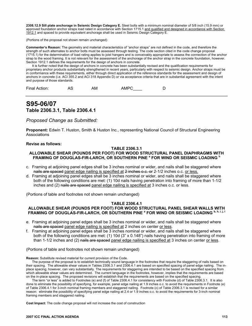
2007 ICC FINAL ACTION AGENDA 113
2308.12.9 Sill plate anchorage in Seismic Design Category E. Steel bolts with a minimum nominal diameter of 5/8 inch (15.9 mm) or approved foundation anchor straps load rated in accordance with Section 1715.1 and qualified and designed in accordance with Section 1912.1 and spaced to provide equivalent anchorage shall be used in Seismic Design Category E. (Portions of the proposal not shown remain unchanged) Commenter=s Reason: The geometry and material characteristics of “anchor straps” are not defined in the code, and therefore the strength of such alternates to anchor bolts must be assessed through testing. The code section cited in the code change proposal (1715.1) for the determination of load rating applies to joist hangers and is conceivably appropriate to assess the connection of the anchor strap to the wood framing. It is not relevant for the assessment of the anchorage of the anchor strap in the concrete foundation, however. Section 1912.1 defines the requirements for the design of anchors in concrete. It is further noted that the design of anchors in concrete has been substantially revised and the qualification requirements for proprietary anchor products substantially strengthened in recent years, particularly with respect to seismic design. Anchor straps must be in conformance with these requirements, either through direct application of the reference standards for the assessment and design of anchors in concrete (i.e. ACI 355.2 and ACI 318 Appendix D) or via acceptance criteria that are in substantial agreement with the intent and purpose of those standards. Final Action: AS AM AMPC D
S95-06/07 Table 2306.3.1, Table 2306.4.1 Proposed Change as Submitted: Proponent: Edwin T. Huston, Smith & Huston Inc., representing National Council of Structural Engineering Associations Revise as follows:
TABLE 2306.3.1 ALLOWABLE SHEAR (POUNDS PER FOOT) FOR WOOD STRUCTURAL PANEL DIAPHRAGMS WITH
FRAMING OF DOUGLAS-FIR-LARCH, OR SOUTHERN PINE a FOR WIND OR SEISMIC LOADING h c. Framing at adjoining panel edges shall be 3 inches nominal or wider, and nails shall be staggered where
nails are spaced panel edge nailing is specified at 2 inches o.c. or 2-1/2 inches o.c. or less. d. Framing at adjoining panel edges shall be 3 inches nominal or wider, and nails shall be staggered where
both of the following conditions are met: (1) 10d nails having penetration into framing of more than 1-1/2 inches and (2) nails are spaced panel edge nailing is specified at 3 inches o.c. or less.
(Portions of table and footnotes not shown remain unchanged)
TABLE 2306.4.1 ALLOWABLE SHEAR (POUNDS PER FOOT) FOR WOOD STRUCTURAL PANEL SHEAR WALLS WITH FRAMING OF DOUGLAS-FIR-LARCH, OR SOUTHERN PINE a FOR WIND OR SEISMIC LOADING b, h, i, j, l
e. Framing at adjoining panel edges shall be 3 inches nominal or wider, and nails shall be staggered where
nails are spaced panel edge nailing is specified at 2 inches on center or less. f. Framing at adjoining panel edges shall be 3 inches nominal or wider, and nails shall be staggered where
both of the following conditions are met: (1) 10d (3” x 0.148”) nails having penetration into framing of more than 1-1/2 inches and (2) nails are spaced panel edge nailing is specified at 3 inches on center or less.
(Portions of table and footnotes not shown remain unchanged) Reason: Substitute revised material for current provision of the Code.
The purpose of the proposal is to establish technically sound language in the footnotes that require the staggering of nails based on their spacing. The allowable shear values in Tables 2306.3.1 and 2306.4.1 are based on specified spacing of panel edge nailing. The in-place spacing, however, can vary substantially. The requirements for staggering are intended to be based on the specified spacing from which allowable shear values are determined. The current language in the footnotes, however, implies that the requirements are based on the in-place spacing. The proposed revisions will establish that the requirements are based on the specified spacing.
The term “or less” is added to Footnotes (e) and (f) of Table 2306.4.1 for consistency with Footnote (d) of Table 2306.3.1. It is also done to eliminate the possibility of specifying, for example, panel edge nailing at 1.9 inches o.c. to avoid the requirements in Footnote (e) of Table 2306.4.1 for 3-inch nominal framing members and staggered nailing. Footnote (c) of Table 2306.3.1 is revised for a similar reason: eliminate the possibility of specifying panel edge nailing at 2.4 or 1.9 inches o.c. to avoid the requirements for 3-inch nominal framing members and staggered nailing. Cost Impact: The code change proposal will not increase the cost of construction
114 2007 ICC FINAL ACTION AGENDA
Committee Action: Disapproved Committee Reason: This proposal was disapproved based on the approval of code change S83-06/07. Assembly Action: None Individual Consideration Agenda This item is on the agenda for individual consideration because a public comment was submitted. Public Comment: Edwin T. Huston, P.E., S.E., Smith & Huston, Inc., Consulting Engineers, representing National Council of Structural Engineering Associations, Code Advisory Committee, requests Approval as Submitted. Commenter=s Reason: At the Orlando hearings, disapproval of Proposal S95 was requested due to committee action on Proposals S82 and S83, which were for approval as amended and approval as submitted, respectively. Proposals S82 and S83, however, do not delete Tables 2306.3.1 and 2306.4.1. Consequently, the proposed revisions to Tables 2306.3.1 and 2306.4.1 in Proposal S95 remain valid. Final Action: AS AM AMPC D
S97-06/07 Table 2306.3.1, Table 2306.4.1, 2307.1.1 Proposed Change as Submitted: Proponent: Edwin T. Huston, Smith & Huston, Inc., representing National Council of Structural Engineering Associations Revise as follows:
TABLE 2306.3.1 ALLOWABLE SHEAR (POUNDS PER FOOT) FOR WOOD STRUCTURAL PANEL DIAPHRAGMS
WITH FRAMING OF DOUGLAS-FIR-LARCH, OR SOUTHERN PINE a FOR WIND OR SEISMIC LOADING h
c. Framing at adjoining panel edges shall be 3 inches nominal or wider, and nails at all panel edges shall be staggered where nails are spaced 2 inches o.c. or 2-1/2 inches o.c.
d. Framing at adjoining panel edges shall be 3 inches nominal or wider, and nails at all panel edges shall be staggered where both of the following conditions are met: (1) 10d nails having penetration into framing of more than 1-1/2 inches and (2) nails are spaced 3 inches o.c. or less.
(Portions of table and footnotes not shown remain unchanged)
TABLE 2306.4.1 ALLOWABLE SHEAR (POUNDS PER FOOT) FOR WOOD STRUCTURAL PANEL SHEAR WALLS WITH FRAMING OF DOUGLAS-FIR-LARCH, OR SOUTHERN PINE a FOR WIND OR SEISMIC LOADING b, h, i, j, l
e. Framing at adjoining panel edges shall be 3 inches nominal or wider, and nails at all panel edges shall be
staggered where nails are spaced 2 inches on center. f. Framing at adjoining panel edges shall be 3 inches nominal or wider, and nails at all panel edges shall be
staggered where both of the following conditions are met: (1) 10d (3” x 0.148”) nails having penetration into framing of more than 1-1/2 inches and (2) nails are spaced 3 inches on center.
h. Where panels are applied on both faces of a wall and nail spacing is less than 6 inches o.c. on either side, panel joints shall be offset to fall on different framing members. Or framing shall be 3-inch nominal or thicker at adjoining panel edges and nails on each side at all panel edges shall be staggered.
i. In Seismic Design Category D, E or F, where shear design values exceed 350 pounds per lineal foot, all framing members receiving edge nailing from abutting panels shall not be less than a single 3-inch nominal member, or two 2-inch nominal members fastened together in accordance with Section 2306.1 to

2007 ICC FINAL ACTION AGENDA 115
transfer the design shear value between framing members. Wood structural panel joint and sill plate nailing shall be staggered in all cases at all panel edges. See Section 2305.3.11 for sill plate size and anchorage requirements.
(Portions of table and footnotes not shown remain unchanged) 2307.1.1 Wood structural panel shear walls. In Seismic Design Category D, E or F, where shear design values exceed 490 pounds per foot (7154 N/m), all framing members receiving edge nailing from abutting panels shall not be less than a single 3-inch (76 mm) nominal member or two 2-inch (51 mm) nominal members fastened together in accordance with AF&PA NDS to transfer the design shear value between framing members. Wood structural panel joint and sill plate nailing shall be staggered in all cases at all panel edges. See Section 2305.3.11 for sill plate size and anchorage requirements. Reason: Substitute revised material for current provision of the code. There is confusion among designers, code officials and contractors concerning application of the requirement for staggering of nails at the panel edges of wood structural panel sheathing. The intent is to stagger the nails transversely and longitudinally along each panel edge at a recommended spacing of 3/8 to 1/2 inch, thus creating two lines of resistance along each panel edge. The confusion comes from the mistaken assumption that the staggering can occur transversely back and forth at the edges of abutting panels, rather than along each panel edge. The proposed revisions will clarify that the staggering of the nails is required at each panel edge. Cost Impact: The code change proposal will not increase the cost of construction. Committee Action: Disapproved Committee Reason: This proposal was disapproved based on the approval of code change S83-06/07. Assembly Action: None Individual Consideration Agenda This item is on the agenda for individual consideration because a public comment was submitted. Public Comment: Edwin T Huston, P.E., S.E., Smith & Huston, Inc., Consulting Engineers, representing National Council of Structural Engineering Associations, Code Advisory Committee, requests Approval as Submitted. Commenter=s Reason: At the Orlando hearings, disapproval of Proposal S97 was requested due to committee action on Proposals S82 and S83, which were for approval as amended and approval as submitted, respectively. Proposals S82 and S83, however, do not delete Tables 2306.3.1 and 2306.4.1 and Section 2307.1.1. Consequently, the proposed revisions to Tables 2306.3.1 and 2306.4.1 and Section 2307.1.1 in Proposal S97 remain valid. Final Action: AS AM AMPC D
S101-06/07 2308.2 Proposed Change as Submitted: Proponent: Randall Shackelford, Simpson Strong-Tie Co. Revise as follows: 2308.2 Limitations. Buildings are permitted to be constructed in accordance with the provisions of conventional light-frame construction, subject to the following limitations, and to further limitations of Sections 2308.11 and 2308.12.
1. Buildings shall be limited to a maximum of three stories above grade plane. For the purposes of this
section, for buildings in Seismic Design Category D or E as determined in Section 1613, cripple stud walls shall be considered to be a story.
Exception: Solid blocked cripple walls not exceeding 14 inches (356 mm) in height need not be considered a story.

116 2007 ICC FINAL ACTION AGENDA
2. Bearing wall floor-to-floor heights shall not exceed a stud height of 10 feet (3048 mm) plus a height of floor framing not to exceed 16 inches (406 mm). 3. Loads as determined in Chapter 16 shall not exceed the following:
3.1. Average dead loads shall not exceed 15 psf (718 N/m2) for combined roof and ceiling, exterior
walls, floors and partitions.
Exceptions:
1. Subject to the limitations of Sections 2308.11.2 and 2308.12.2, stone or masonry veneer up to the lesser of 5 inches (127 mm) thick or 50 psf (2395 N/m2) and installed in accordance with Chapter 14 is permitted to a height of 30 feet (9144 mm) above a noncombustible foundation, with an additional 8 feet (2438 mm) permitted for gable ends.
2. Concrete or masonry fireplaces, heaters and chimneys shall be permitted in accordance with the provisions of this code.
3.2. Live loads shall not exceed 40 psf (1916 N/m2) for floors. 3.3. Ground snow loads shall not exceed 50 psf (2395 N/m2).
4. Wind speeds shall not exceed 100 miles per hour (mph) (44 m/s) (3-second gust).
Exception: Wind speeds shall not exceed 110 mph (48.4 m/s) (3-second gust) for buildings in Exposure Category B that are not located in a hurricane prone region.
5. Roof trusses and rafters shall not span more than 40 feet (12 192 mm) between points of vertical
support. 6. The use of the provisions for conventional light-frame construction in this section shall not be permitted
for Occupancy Category IV buildings assigned to Seismic Design Category B, C, D, E or F, as determined in Section 1613.
7. Conventional light-frame construction is limited in irregular structures in Seismic Design Category D or E, as specified in Section 2308.12.6.
Reason: The purpose of this proposal is to revise wind limitation in the IBC to match the IRC
Studies conducted by the Institute for Business and Home Safety show that the conventional construction requirements of the IBC and IRC are frequently inadequate for wood buildings built where the design windspeed exceeds 100 mph. The IRC was revised to reflect this last code change cycle, but the IBC was not. This change will make the IRC and IBC have the same limitations. Cost Impact: The code change proposal will increase the cost of construction in areas between 100 and 110 miles per hour if the buildings are currently being built without consideration of wind forces. Committee Action: Approved as Submitted Committee Reason: This code change aligns the wind limitations for the IBC conventional construction provisions with those in the IRC. Assembly Action: None Individual Consideration Agenda This item is on the agenda for individual consideration because a public comment was submitted. Public Comment: Gary J. Ehrlich, P.E., National Association of Home Builders, Washington, D.C., requests Disapproval. Commenter=s Reason: IBHS’s proposal in the last cycle (RB31-04/05) only raised concerns regarding the IRC provisions, not the IBC provisions. As justification for the IRC code change they noted four issues: toe-nailed uplift connections, wall-to-wall connections at the floor line, roof sheathing nails, and wind bracing requirements. In lieu of pursuing the individual modifications needed to resolve these issues within the IRC, the proponent simply lowered the ceiling for using prescriptive design provisions along the Atlantic Coast. We believe this was an excessive solution to the problem. The 2006 IBC increased the required roof sheathing nailing from 6d to 8d common nails (Table 2304.9.1, Item #31, footnote l), which answers the concerns about attachment of roof sheathing. Meanwhile, Section 2308.10.1 and Table 2308.10.1 clearly specify ties or connectors for roof truss and rafter attachments to wall framing, as opposed to simply toe nails. Thus, any concerns regarding roof sheathing and truss/rather uplift are adequately addressed by the current IBC conventional provisions.

2007 ICC FINAL ACTION AGENDA 117
The braced wall provisions of Section 2308.9 are a reduced set of the IRC provisions and have not been modified to the same extent as in IRC. Many of the exceptions found in the IRC (for example, the 50’-0” spacing allowed under R602.10.1.1) are not present. Thus, the concerns about weaknesses in the IRC provisions do not carry over to the IBC. In addition, the approved change raises questions regarding the age of the structures used for justifying the code change. FEMA and NIST reports on the 2004 and 2005 hurricanes indicated that structures built to the 2000 and 2003 IRC performed extremely well. Lowering the trigger for using SSTD-10, WFCM, ASCE 7 and COFS/PM subjects residential structures to conservative design requirements for elements (e.g. foundations and masonry walls) which have shown excellent performance in 100-110mph basic wind zones. Thus, forcing the use of special design provisions in the 100mph zone is therefore not needed and will needlessly burden builders and inspectors who are responsible for ensuring the more conservative provisions are met. In turn, this will result in increased construction and inspection costs that consumers (especially first-time home buyers) must bear without providing them with a needed benefit. Furthermore, research is currently being conducted by ARA Associates, who originally developed the ASCE wind zone map, and others to verify the hurricane and storm models used to develop the current contours of the wind zone map in hurricane-prone areas. This research suggests the existing wind zone map is excessively conservative. Therefore, changes to the triggers for conventional construction should be limited pending the completion of the research. NAHB asks for your support in disapproving this proposal and reversing the committee’s action. Final Action: AS AM AMPC D
S105-06/07, Part I 2406.1.1, 2406.2, Chapter 35 Proposed Change as Submitted: Proponent: William E. Koffel, P.E., Koffel Associates, Inc., representing Glazing Industry Code Committee PART I – IBC STRUCTURAL 1. Revise as follows: 2406.1.1 CPSC 16 CFR 1201. Impact test. Except as provided in Sections 2406.1.2 through 2406.1.4, all glazing shall pass the impact test requirements of CPSC 16 CFR 1201, listed in Chapter 35 Section 2406.2. Glazing shall comply with the CPSC 16 CFR, Part 1201 criteria, for Category I or II as indicated in Table 2406.1. 2. Add new text as follows: 2406.2 Impact test. Where required by other sections of the Code, glazing shall be tested in accordance with CPSC 16 CFR 1201. Glazing shall comply with the test criteria for Category I or II as indicated in Table 2406.2(1)
Exception: Glazing not in doors or enclosures for hot tubs, whirlpools, saunas, steam rooms, bathtubs and showers shall be permitted to be tested in accordance with ANSI Z97.1. Glazing shall comply with the test criteria for Class A or B as indicated in Table 2406.2(2).
3. Revise table as follows:
TABLE 2406.1 2406.2(1) MINIMUM CATEGORY CLASSIFICATION OF GLAZING USING CPSC 16 CFR 1201
(No change to table entries)

118 2007 ICC FINAL ACTION AGENDA
4. Add new table as follows:
TABLE 2406.2(2) MINIMUM CATEGORY CLASSIFICATION OF GLAZING USING ANSI Z97.1
5. Revise Chapter 35 as follows: ANSI
Z97.1-84 (R1994) 04
Reason: In 1977, the U.S. Consumer Products Safety Commission (“CPSC”) adopted as a mandatory federal safety regulation Safety Standard for Architectural Glazing Materials, codified at 16 CFR Part 1201. The CPSC amended its Safety Standard for Architectural Glazing Materials on several occasions subsequent to its initial adoption, the last time on June 28, 1982.
Set forth below are the more significant differences between these two standards, both standards applicable to safety glazing materials used in architectural applications. This reason statement makes no attempt to summarize all pertinent provisions of the two standards, only their significant differences.
The principal differences between the CPSC’s 16 CFR 1201 standard and the ANSI Z97.1-2004 standard relate to their scope and function. The CPSC standard is not only a test method and a procedure for determining the safety performance of architectural glazing, but also a federal standard that mandates where and when safety glazing materials must be used in architectural applications and preempts any non-identical state or local standard. In contrast, ANSI Z97 is only a voluntary safety performance specification and test method. It does not purport to indicate where and when safety glazing materials must be used, leaving those determinations up to the building codes and to glass and fenestration specifiers. In this instance, the IBC provides the requirements regarding the safety performance of architectural glazing beyond that which is covered by the federal standard.
The CPSC requires the installation of safety glazing materials meeting 16 CFR 1201 only in storm doors, combination doors, entrance-exit doors, sliding patio doors, closet doors, and shower and tub doors and enclosures. Other than that, meeting CPSC’s requirements is necessary only when and if a building code authority or other jurisdiction adopting safety glazing laws specifically mandates that safety glazing comply with the CPSC standard, 16 CFR 1201 -- and most building codes do. ANSI Z97, as a voluntary standard, applies only when, where, and if it is adopted by a building code authority or is specified in the approved plans and specifications of the architect, building contractor, or other glass specifier.
Test Specimens: For impact testing, the CPSC requires only one specimen of each nominal thickness be submitted for testing and specifies it must be the largest size the manufacturer produces up to a maximum of size of 34″ by 76″. ANSI Z97 requires that four specimens of each nominal thickness and size must be impact-tested. The manufacturer has the option of testing either 34″ by 76″ specimens or the largest size it commercially produces less than 34″ by 76″, but with a minimum size of 24″ by 30″. A nominal thickness is defined as +/- ⅛-inch.
Types of Glass: The CPSC standard has no performance tests for plastics or for bent glass. ANSI Z97 has specific tests for both. The CPSC standard does not prohibit the use of ordinary annealed glass in hazardous locations as long as it passes the appropriate impact tests, consistent with the concept of a performance based impact test. (Thick, heavy annealed glass is likely to pass the CPSC 18-inch drop-height and 48-inch drop-height impact tests for Category I and II locations.) ANSI Z97.1-2004 contains an express limitation on annealed glass: “Monolithic annealed in any thickness is not considered safety glazing material under this standard.”
Asymmetrical Glazing Material: The CPSC standard requires all asymmetrical glazing materials to be impacted on both sides of each specimen and then evaluated under the pass-fail criteria. There is no exception. ANSI Z97 requires that, with the exception of mirror glazing, all asymmetrical glass specimens must be impacted on both sides, two on one side and two on the other. With respect to mirror glazing products using reinforced or non-reinforced organic adhesive backing, all four specimens must be impacted only on the non-reinforced side “and with no other material applied.”
Impact Categories or Levels: The CPSC standard has two distinct impact levels or categories, Category I and Category II, and specifies which defined hazardous location must contain Category II safety glazing materials and which may use Category I glazing materials. Glazing material successfully passing the impact test of a 48-inch drop height, a 400 foot-pound impact, is classified as “Category II” glass. Glazing material passing the 18-inch drop height, a 150 foot-pounds impact, is classified as “Category I” glass. ANSI Z97 has adopted three separate impact categories or classes, based upon impact performance. ANSI Z97’s Class A glazing materials are comparable to the CPSC’s Category II glazing materials, passing a 48-inch drop height test, and its Class B glazing materials are comparable to the CPSC’s Category I glazing materials, passing the 18-inch drop height test. ANSI Z97 also has a product-specific Class C impact test, a 12-inch drop height test, applicable only for fire-resistant glazing materials. However, the proposed code change does not identify Class C as an acceptable product for use in hazardous locations.
Pass-Fail Impact Criteria: The CPSC standard, like the ANSI standard, offers alternative criteria for evaluating whether a test specimen passes the impact test. The CPSC standard considers the specimen a pass if a 3-inch diameter solid steel ball, weighing 4 lbs., will not pass through the opening when placed on the specimen for one second. ANSI uses the 3-inch sphere measure, but does not require the sphere be a steel ball and does not specify the weight of the 3-inch sphere, but does require that the sphere not pass freely through the opening when a force of 4 lbs. is applied to the sphere. There is no time element associated with this alternative.
EXPOSED SURFACE
AREA OF ONE SIDE OF ONE LITE
GLAZING IN STORM OR
COMBINATION DOORS
(Category class)
GLAZING IN DOORS
(Category class)
GLAZED PANELS
REGULATED BY
ITEM 7 OF SECTION
2406.3 (Category
class)
GLAZED PANELS
REGULATED BY
ITEM 6 OF SECTION
2406.3 (Category
class)
DOORS AND ENCLOSURES REGULATED
BY ITEM 5 OF SECTION
2406.3 (Category
class)
SLIDING GLASS
DOORS PATIO TYPE
(Category class)
9 square feet or less
B B No requirement
B A A
More than 9 square feet
A A A A A A
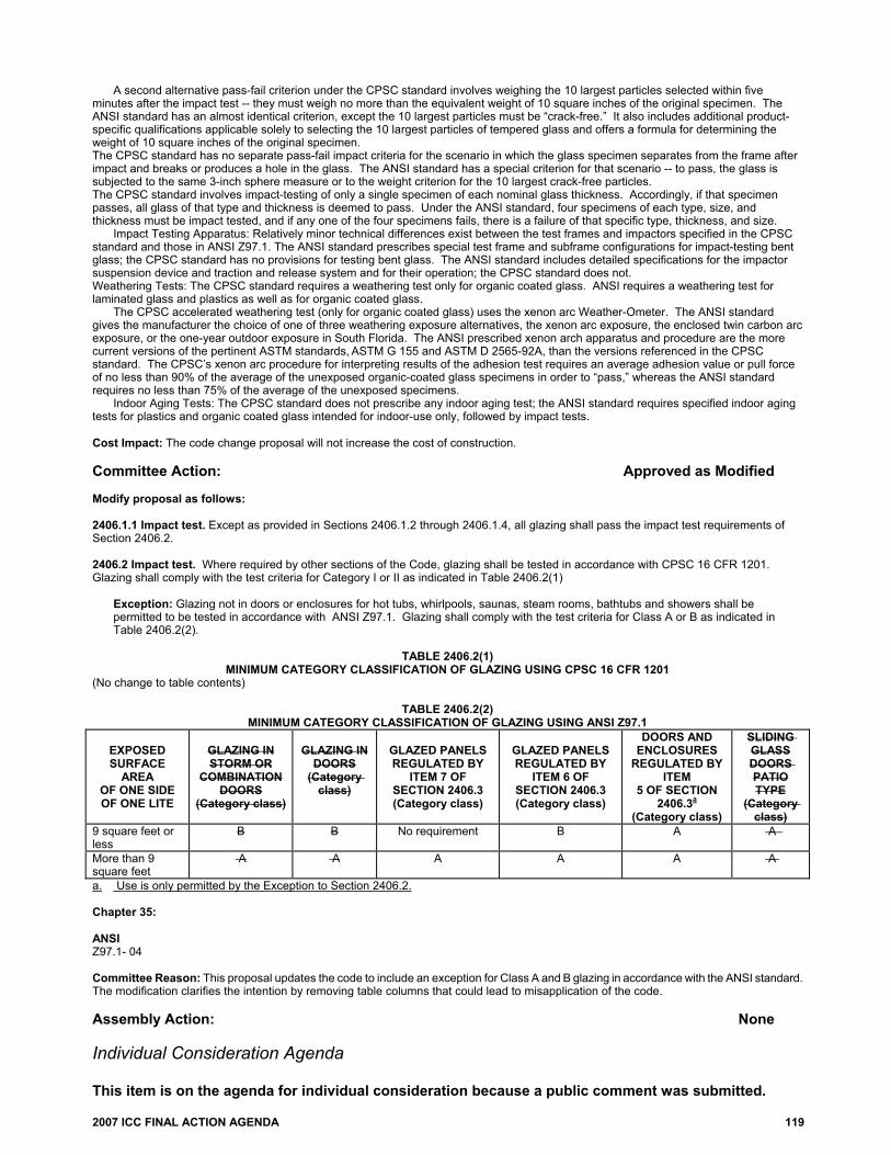
2007 ICC FINAL ACTION AGENDA 119
A second alternative pass-fail criterion under the CPSC standard involves weighing the 10 largest particles selected within five minutes after the impact test -- they must weigh no more than the equivalent weight of 10 square inches of the original specimen. The ANSI standard has an almost identical criterion, except the 10 largest particles must be “crack-free.” It also includes additional product-specific qualifications applicable solely to selecting the 10 largest particles of tempered glass and offers a formula for determining the weight of 10 square inches of the original specimen. The CPSC standard has no separate pass-fail impact criteria for the scenario in which the glass specimen separates from the frame after impact and breaks or produces a hole in the glass. The ANSI standard has a special criterion for that scenario -- to pass, the glass is subjected to the same 3-inch sphere measure or to the weight criterion for the 10 largest crack-free particles. The CPSC standard involves impact-testing of only a single specimen of each nominal glass thickness. Accordingly, if that specimen passes, all glass of that type and thickness is deemed to pass. Under the ANSI standard, four specimens of each type, size, and thickness must be impact tested, and if any one of the four specimens fails, there is a failure of that specific type, thickness, and size.
Impact Testing Apparatus: Relatively minor technical differences exist between the test frames and impactors specified in the CPSC standard and those in ANSI Z97.1. The ANSI standard prescribes special test frame and subframe configurations for impact-testing bent glass; the CPSC standard has no provisions for testing bent glass. The ANSI standard includes detailed specifications for the impactor suspension device and traction and release system and for their operation; the CPSC standard does not. Weathering Tests: The CPSC standard requires a weathering test only for organic coated glass. ANSI requires a weathering test for laminated glass and plastics as well as for organic coated glass. The CPSC accelerated weathering test (only for organic coated glass) uses the xenon arc Weather-Ometer. The ANSI standard gives the manufacturer the choice of one of three weathering exposure alternatives, the xenon arc exposure, the enclosed twin carbon arc exposure, or the one-year outdoor exposure in South Florida. The ANSI prescribed xenon arch apparatus and procedure are the more current versions of the pertinent ASTM standards, ASTM G 155 and ASTM D 2565-92A, than the versions referenced in the CPSC standard. The CPSC’s xenon arc procedure for interpreting results of the adhesion test requires an average adhesion value or pull force of no less than 90% of the average of the unexposed organic-coated glass specimens in order to “pass,” whereas the ANSI standard requires no less than 75% of the average of the unexposed specimens.
Indoor Aging Tests: The CPSC standard does not prescribe any indoor aging test; the ANSI standard requires specified indoor aging tests for plastics and organic coated glass intended for indoor-use only, followed by impact tests. Cost Impact: The code change proposal will not increase the cost of construction. Committee Action: Approved as Modified Modify proposal as follows: 2406.1.1 Impact test. Except as provided in Sections 2406.1.2 through 2406.1.4, all glazing shall pass the impact test requirements of Section 2406.2. 2406.2 Impact test. Where required by other sections of the Code, glazing shall be tested in accordance with CPSC 16 CFR 1201. Glazing shall comply with the test criteria for Category I or II as indicated in Table 2406.2(1)
Exception: Glazing not in doors or enclosures for hot tubs, whirlpools, saunas, steam rooms, bathtubs and showers shall be permitted to be tested in accordance with ANSI Z97.1. Glazing shall comply with the test criteria for Class A or B as indicated in Table 2406.2(2).
TABLE 2406.2(1)
MINIMUM CATEGORY CLASSIFICATION OF GLAZING USING CPSC 16 CFR 1201 (No change to table contents)
TABLE 2406.2(2) MINIMUM CATEGORY CLASSIFICATION OF GLAZING USING ANSI Z97.1
EXPOSED SURFACE
AREA OF ONE SIDE OF ONE LITE
GLAZING IN STORM OR
COMBINATION DOORS
(Category class)
GLAZING IN
DOORS (Category
class)
GLAZED PANELS REGULATED BY
ITEM 7 OF SECTION 2406.3 (Category class)
GLAZED PANELS REGULATED BY
ITEM 6 OF SECTION 2406.3 (Category class)
DOORS AND ENCLOSURES
REGULATED BY ITEM
5 OF SECTION 2406.3a
(Category class)
SLIDING GLASS DOORS PATIO TYPE
(Category class)
9 square feet or less
B B No requirement B A A
More than 9 square feet
A A A A A A
a. Use is only permitted by the Exception to Section 2406.2. Chapter 35: ANSI Z97.1- 04 Committee Reason: This proposal updates the code to include an exception for Class A and B glazing in accordance with the ANSI standard. The modification clarifies the intention by removing table columns that could lead to misapplication of the code. Assembly Action: None Individual Consideration Agenda This item is on the agenda for individual consideration because a public comment was submitted.

120 2007 ICC FINAL ACTION AGENDA
Public Comment: Donn Harter, representing Fire & Safety Glazing Council, requests Disapproval for Part I. Commenter=s Reason: There are numerous conflicts between the ANSI Z97.1 test standard and the CPSC safety glazing test requirements, which will cause confusion and conflicts in testing safety glazing to two standards. The CPSC standard is mandatory for safety glazing in doors, and testing to the ANSI standard is preempted. The Residential Code Committee action was appropriate in disapproving this code change for the IRC, and it should likewise be disapproved for the IBC. Final Action: AS AM AMPC D
S105-06/07, Part II R308.3, R308.3.1 Proposed Change as Submitted: Proponent: William E. Koffel, P.E., Koffel Associates, Inc., representing Glazing Industry Code Committee PART II – IRC BUILDING/ENERGY 1. Revise as follows: R308.3 Human impact loads. Individual glazed areas, including glass mirrors in hazardous locations such as those indicated as defined in Section R308.4, shall pass the test requirements of CPSC 16 CFR, Part 1201 Section 308.3.1. Glazing shall comply with CPSC 16 CFR, Part 1201 criteria for Category I or Category II as indicated in Table R308.3.
Exception: Louvered windows and jalousies shall comply with Section R308.2. 2. Add new text as follows: R308.3.1 Impact Test. Where required by other sections of the Code, glazing shall be tested in accordance with CPSC 16 CFR 1201. Glazing shall comply with the test criteria for Category I or II as indicated in Table R308.3.1(1).
Exception: Glazing not in doors or enclosures for hot tubs, whirlpools, saunas, steam rooms, bathtubs and showers shall be permitted to be tested in accordance with ANSI Z97.1. Glazing shall comply with the test criteria for Class A or B as indicated in Table R308.3.1 (2).
3. Revise table as follows: TABLE R308.3 R308.3.1(1)
MINIMUM CATEGORY CLASSIFICATION OF GLAZING USING CPSC 16 CFR 1201 (Portions of table not shown remain unchanged) 3. Add new table as follows:
TABLE R308.3.1(2) MINIMUM CATEGORY CLASSIFICATION OF GLAZING USING ANSI Z97.1
EXPOSED SURFACE
AREA OF ONE SIDE OF ONE LITE GLAZING IN
GLAZING IN STORM OR
COMBINATION DOORS
(Category class)
GLAZING IN DOORS
(Category class)
GLAZED PANELS
REGULATED BY ITEM 7 OF
SECTION 2406.3 (Category class)
GLAZED PANELS
REGULATED BY
ITEM 6 OF SECTION
2406.3 (Category class)
DOORS AND ENCLOSURES REGULATED
BY ITEM 5 OF SECTION
2406.3 (Category class)
SLIDING GLASS DOORS PATIO TYPE
(Category class)
9 square feet or less B B No requirement B A A
More than 9 square fee A A A A A A
For SI: 1 square foot = 0.0929 m2.

2007 ICC FINAL ACTION AGENDA 121
Reason: In 1977, the U.S. Consumer Products Safety Commission (“CPSC”) adopted as a mandatory federal safety regulation Safety Standard for Architectural Glazing Materials, codified at 16 CFR Part 1201. The CPSC amended its Safety Standard for Architectural Glazing Materials on several occasions subsequent to its initial adoption, the last time on June 28, 1982.
Set forth below are the more significant differences between these two standards, both standards applicable to safety glazing materials used in architectural applications. This reason statement makes no attempt to summarize all pertinent provisions of the two standards, only their significant differences.
The principal differences between the CPSC’s 16 CFR 1201 standard and the ANSI Z97.1-2004 standard relate to their scope and function. The CPSC standard is not only a test method and a procedure for determining the safety performance of architectural glazing, but also a federal standard that mandates where and when safety glazing materials must be used in architectural applications and preempts any non-identical state or local standard. In contrast, ANSI Z97 is only a voluntary safety performance specification and test method. It does not purport to indicate where and when safety glazing materials must be used, leaving those determinations up to the building codes and to glass and fenestration specifiers. In this instance, the IBC provides the requirements regarding the safety performance of architectural glazing beyond that which is covered by the federal standard.
The CPSC requires the installation of safety glazing materials meeting 16 CFR 1201 only in storm doors, combination doors, entrance-exit doors, sliding patio doors, closet doors, and shower and tub doors and enclosures. Other than that, meeting CPSC’s requirements is necessary only when and if a building code authority or other jurisdiction adopting safety glazing laws specifically mandates that safety glazing comply with the CPSC standard, 16 CFR 1201 -- and most building codes do. ANSI Z97, as a voluntary standard, applies only when, where, and if it is adopted by a building code authority or is specified in the approved plans and specifications of the architect, building contractor, or other glass specifier.
Test Specimens: For impact testing, the CPSC requires only one specimen of each nominal thickness be submitted for testing and specifies it must be the largest size the manufacturer produces up to a maximum of size of 34″ by 76″. ANSI Z97 requires that four specimens of each nominal thickness and size must be impact-tested. The manufacturer has the option of testing either 34″ by 76″ specimens or the largest size it commercially produces less than 34″ by 76″, but with a minimum size of 24″ by 30″. A nominal thickness is defined as +/- ⅛-inch.
Types of Glass: The CPSC standard has no performance tests for plastics or for bent glass. ANSI Z97 has specific tests for both. The CPSC standard does not prohibit the use of ordinary annealed glass in hazardous locations as long as it passes the appropriate impact tests, consistent with the concept of a performance based impact test. (Thick, heavy annealed glass is likely to pass the CPSC 18-inch drop-height and 48-inch drop-height impact tests for Category I and II locations.) ANSI Z97.1-2004 contains an express limitation on annealed glass: “Monolithic annealed in any thickness is not considered safety glazing material under this standard.”
Asymmetrical Glazing Material: The CPSC standard requires all asymmetrical glazing materials to be impacted on both sides of each specimen and then evaluated under the pass-fail criteria. There is no exception. ANSI Z97 requires that, with the exception of mirror glazing, all asymmetrical glass specimens must be impacted on both sides, two on one side and two on the other. With respect to mirror glazing products using reinforced or non-reinforced organic adhesive backing, all four specimens must be impacted only on the non-reinforced side “and with no other material applied.”
Impact Categories or Levels: The CPSC standard has two distinct impact levels or categories, Category I and Category II, and specifies which defined hazardous location must contain Category II safety glazing materials and which may use Category I glazing materials. Glazing material successfully passing the impact test of a 48-inch drop height, a 400 foot-pound impact, is classified as “Category II” glass. Glazing material passing the 18-inch drop height, a 150 foot-pounds impact, is classified as “Category I” glass. ANSI Z97 has adopted three separate impact categories or classes, based upon impact performance. ANSI Z97’s Class A glazing materials are comparable to the CPSC’s Category II glazing materials, passing a 48-inch drop height test, and its Class B glazing materials are comparable to the CPSC’s Category I glazing materials, passing the 18-inch drop height test. ANSI Z97 also has a product-specific Class C impact test, a 12-inch drop height test, applicable only for fire-resistant glazing materials. However, the proposed code change does not identify Class C as an acceptable product for use in hazardous locations.
Pass-Fail Impact Criteria: The CPSC standard, like the ANSI standard, offers alternative criteria for evaluating whether a test specimen passes the impact test. The CPSC standard considers the specimen a pass if a 3-inch diameter solid steel ball, weighing 4 lbs., will not pass through the opening when placed on the specimen for one second. ANSI uses the 3-inch sphere measure, but does not require the sphere be a steel ball and does not specify the weight of the 3-inch sphere, but does require that the sphere not pass freely through the opening when a force of 4 lbs. is applied to the sphere. There is no time element associated with this alternative.
A second alternative pass-fail criterion under the CPSC standard involves weighing the 10 largest particles selected within five minutes after the impact test -- they must weigh no more than the equivalent weight of 10 square inches of the original specimen. The ANSI standard has an almost identical criterion, except the 10 largest particles must be “crack-free.” It also includes additional product-specific qualifications applicable solely to selecting the 10 largest particles of tempered glass and offers a formula for determining the weight of 10 square inches of the original specimen. The CPSC standard has no separate pass-fail impact criteria for the scenario in which the glass specimen separates from the frame after impact and breaks or produces a hole in the glass. The ANSI standard has a special criterion for that scenario -- to pass, the glass is subjected to the same 3-inch sphere measure or to the weight criterion for the 10 largest crack-free particles. The CPSC standard involves impact-testing of only a single specimen of each nominal glass thickness. Accordingly, if that specimen passes, all glass of that type and thickness is deemed to pass. Under the ANSI standard, four specimens of each type, size, and thickness must be impact tested, and if any one of the four specimens fails, there is a failure of that specific type, thickness, and size.
Impact Testing Apparatus: Relatively minor technical differences exist between the test frames and impactors specified in the CPSC standard and those in ANSI Z97.1. The ANSI standard prescribes special test frame and subframe configurations for impact-testing bent glass; the CPSC standard has no provisions for testing bent glass. The ANSI standard includes detailed specifications for the impactor suspension device and traction and release system and for their operation; the CPSC standard does not.
Weathering Tests: The CPSC standard requires a weathering test only for organic coated glass. ANSI requires a weathering test for laminated glass and plastics as well as for organic coated glass. The CPSC accelerated weathering test (only for organic coated glass) uses the xenon arc Weather-Ometer. The ANSI standard gives the manufacturer the choice of one of three weathering exposure alternatives, the xenon arc exposure, the enclosed twin carbon arc exposure, or the one-year outdoor exposure in South Florida. The ANSI prescribed xenon arch apparatus and procedure are the more current versions of the pertinent ASTM standards, ASTM G 155 and ASTM D 2565-92A, than the versions referenced in the CPSC standard. The CPSC’s xenon arc procedure for interpreting results of the adhesion test requires an average adhesion value or pull force of no less than 90% of the average of the unexposed organic-coated glass specimens in order to “pass,” whereas the ANSI standard requires no less than 75% of the average of the unexposed specimens.
Indoor Aging Tests: The CPSC standard does not prescribe any indoor aging test; the ANSI standard requires specified indoor aging tests for plastics and organic coated glass intended for indoor-use only, followed by impact tests.

122 2007 ICC FINAL ACTION AGENDA
Cost Impact: The code change proposal will not increase the cost of construction. Committee Action: Disapproved Committee Reason: There was a modification proposed to this code change proposal when it was heard by the structural committee. The IRC B/E committee voted to disapprove the proposed change since the modification was not also brought before this committee. The proponent was not present to answer questions or provide the modification. Assembly Action: None Individual Consideration Agenda This item is on the agenda for individual consideration because a public comment was submitted. Public Comment: William E. Koffel, P.E., Koffel Associates, Inc., representing Glazing Industry Code Committee, requests Approval as Modified by this Public Comment for Part II. Modify proposal as follows:
TABLE 308.3.1(2)
MINIMUM CATEGORY CLASSIFICATION OF GLAZING USING ANSI Z97.1
EXPOSED SURFACE
AREA OF ONE SIDE OF ONE
LITE
GLAZING IN STORM OR
COMBINATION DOORS
(Category class)
GLAZING INDOORS
(Category class)
GLAZED PANELS REGULATED BY
ITEM 7 OF SECTION R308.4 (Category class)
GLAZED PANELS REGULATED BY
ITEM 6 OF SECTION R308.4 (Category class)
DOORS AND ENCLOSURES
REGULATED BY ITEM 5 OF SECTION R308.4a
(Category class)
SLIDING GLASS DOORS
PATIO TYPE (Category
class) 9 square feet or less B B No requirement B A A
More than 9 square fee A A A A A A
For SI: 1 square foot = 0.0929 m2. a. Use is only permitted by the Exception to Section R308.3.1. (Portions of the proposal not shown remain unchanged) Commenter=s Reason: The modification proposed is technically the same as the modification accepted in Part I of the code change proposal. As noted in the Committee Reason, the modification was not submitted during the hearing discussion on Part II of the code change proposal. Approval of the code change as modified by the Public Comment will be consistent with the action taken on Part II of the code change. Final Action: AS AM AMPC D
S106-06/07, Part I 2406.2.1, 2407.1, 2408.2.1, 2408.3 Proposed Change as Submitted: Proponent: William E. Koffel, P.E., Koffel Associates, Inc., representing Glazing Industry Code Committee PART I – IBC STRUCTURAL Revise as follows: 2406.2.1 Multilight assemblies. Multilight glazed assemblies having individual lights not exceeding 1 square foot (0.09 m2) in exposed areas shall have at least one light in the assembly marked as indicated in Section 2406.2. Other lights in the assembly shall be marked “CPSC 16 CFR 1201” “or ANSI Z97.1,” as appropriate. 2407.1 Materials. Glass used as a handrail assembly or a guard section shall be constructed of either single fully tempered glass, laminated fully tempered glass or laminated heat-strengthened glass. Glazing in railing in-fill panels shall be of an approved safety glazing material that conforms to the provisions of Section

2007 ICC FINAL ACTION AGENDA 123
2406.1.1. For all glazing types, the minimum nominal thickness shall be 1/4 inch (6.4 mm). Fully tempered glass and laminated glass shall comply with Category II of CPSC 16 CFR 1201, or Class A of ANSI Z97.1, listed in Chapter 35. 2408.2.1 Testing. Test methods and loads for individual glazed areas in racquetball and squash courts subject to impact loads shall conform to those of CPSC 16 CFR, Part 1201 or ANSI Z97.1, listed in Chapter 35, with impacts being applied at a height of 59 inches (1499 mm) above the playing surface to an actual or simulated glass wall installation with fixtures, fittings and methods of assembly identical to those used in practice. Glass walls shall comply with the following conditions:
1. A glass wall in a racquetball or squash court, or similar use subject to impact loads, shall remain intact following a test impact.
2. The deflection of such walls shall not be greater than 11/2 inches (38 mm) at the point of impact for a drop height of 48 inches (1219 mm).
Glass doors shall comply with the following conditions:
1. Glass doors shall remain intact following a test impact at the prescribed height in the center of the door. 2. The relative deflection between the edge of a glass door and the adjacent wall shall not exceed the
thickness of the wall plus 1/2 inch (12.7 mm) for a drop height of 48 inches (1219 mm). 2408.3 Gymnasiums and basketball courts. Glazing in multipurpose gymnasiums, basketball courts and similar athletic facilities subject to human impact loads shall comply with Category II of CPSC 16 CFR 1201, or Class A of ANSI Z97.1, listed in Chapter 35. Reason: (IBC) For the most part the proposal is a companion to the GICC proposal to recognize ANSI Z97.1 as an alternative test procedure to CPSC 16 CFR 1201 for products not regulated by the federal standard. However, the proposal also addresses some other editorial issues. Section 2406.2.1 – returns to the language in the 2003 Edition of the IBC recognizing both test standards. Section 2407.1 – recognizes the ANSI Z97.1 test standard. Section 2408.2.1 – editorial clean-up with respect to the reference to the CPSC standard for consistency purposes and recognizes the ANSI Z97.1 test standard. Section 2408.1 – recognizes the ANSI Z97.1 test standard. It should be noted that Section 2409 already recognizes both test standards so a change was not necessary. Cost Impact: The code change proposal will not increase the cost of construction. Committee Action: Approved as Submitted Committee Reason: The code change adds an appropriate standard reference and is consistent with the action on S105-06/07. Assembly Action: None Individual Consideration Agenda This item is on the agenda for individual consideration because a public comment was submitted. Public Comment: Donn Harter, Fire & Safety Glazing Council, requests Disapproval for Part I. Commenter=s Reason: There are numerous conflicts between the ANSI Z97.1 test standard and the CPSC safety glazing test requirements, which will cause confusion and conflicts in testing safety glazing to two standards. The CPSC standard is mandatory for safety glazing in doors, and testing to the ANSI standard is preempted. The Residential Code Committee action was appropriate in disapproving this code change for the IRC, and it should likewise be disapproved for the IBC. Final Action: AS AM AMPC D

124 2007 ICC FINAL ACTION AGENDA
S106-06/07, Part II R308.1.1. Proposed Change as Submitted: Proponent: William E. Koffel, P.E., Koffel Associates, Inc., representing Glazing Industry Code Committee PART II – IRC BUILDING/ENERGY Revise as follows: R308.1.1 Identification of multiple assemblies. Multipane assemblies having individual panes not exceeding 1 square foot (0.09 m2) in exposed area shall have at least one pane in the assembly identified in accordance with Section R308.1. All other panes in the assembly shall be labeled “CPSC 16 CFR 1201” or “ANSI Z97.1” as appropriate. Reason: (IRC) The proposal is a companion to the GICC proposal to recognize ANSI Z97.1 as an alternative test procedure to CPSC 16 CFR 1201 for products not regulated by the federal standard. The proposal also inserts the letters “CPSC” in the mark to be consistent with the requirements in the IBC. Cost Impact: The code change proposal will not increase the cost of construction. Committee Action: Disapproved Committee Reason: The two standards; CPSC 16 CFR and the standard proposed to be added ANSI Z97.1 are not the same and should not be listed as alternatives for one another. Assembly Action: None Individual Consideration Agenda This item is on the agenda for individual consideration because a public comment was submitted. Public Comment: William E. Koffel, P.E., Koffel Associates, Inc., representing Glazing Industry Code Committee, requests Approval as Submitted for Part II. Commenter=s Reason: S106-06/07, Part II was disapproved because S105-06/07, Part II was disapproved. A separate Public Comment has been submitted to address the modification that was not available during the discussion of S105-06/07. If the result of the Final Action Hearings is to Approve S105-06/07 as Modified by the Public Comment, approval of S106-06/07, Part II is merely correlative with that action. Final Action: AS AM AMPC D
S108-06/07 2407.1.2 Proposed Change as Submitted: Proponent: William E. Koffel, P.E., Koffel Associates, Inc., representing Glazing Industry Code Committee Revise as follows: 2407.1.2 Support. Each handrail or guard section shall be supported by a minimum of three glass balusters or shall be otherwise supported to remain in place should one baluster panel fail. Glass balusters shall not be installed without an attached handrail or guard.
Exception: A top rail shall not be required where the glass balusters are laminated glass with two or more glass plies of equal thickness and the same glass type. The panels shall be designed to withstand the loads specified in Section 1607.7.

2007 ICC FINAL ACTION AGENDA 125
Reason: At the time the provisions of Section 2407.1.2 were developed the dominant glass used for baluster panels was single tempered glass. This glass was structurally adequate and had been successfully used. The required top rail was to provide a degree of protection should one baluster fail for any reason. Tempered glass characteristically may fail in a manner where it evacuates the opening.
In some applications the use of a top rail is an undesirable visual barrier. A typical example is the guard at the front of the spectator levels of sport arenas and theaters. In a number of these installations the top rail has been eliminated. The balusters have been laminated heat-strengthened or tempered glass complying with the IBC structural requirements for top rails. Variances from Section 2407.1.2 have been historically granted by building officials.
If one ply of the laminated glass breaks, the glass will remain in place. Unlike single tempered glass, it will not evacuate the opening. Even in the rare instance where both plies may simultaneously fail, the glass will remain in place.
It should be noted that the GICC has submitted another code change which proposes to delete Section 2407.1.2 in favor of reference two ASTM standards. If the section is deleted as recommended in the other proposal, the proposed exception is not required and this proposal should be recommended for Disapproval. Cost Impact: The code change proposal will not increase the cost of construction. Committee Action: Approved as Modified Modify proposal as follows: 2407.1.2 Support. Each handrail or guard section shall be supported by a minimum of three glass balusters or shall be otherwise supported to remain in place should one baluster panel fail. Glass balusters shall not be installed without an attached handrail or guard.
Exception: A top rail shall not be required where the glass balusters are laminated glass with two or more glass plies of equal thickness and the same glass type when approved by the building official. The panels shall be designed to withstand the loads specified in Section 1607.7.
Committee Reason: The code change adds an option to a top rail that is now often permitted as an alternative method. The modification requires the approval of the building official and is intended to address a concern that in some uses such as schools and hospitals, glass breakage is not acceptable. Assembly Action: None Individual Consideration Agenda This item is on the agenda for individual consideration because a public comment was submitted. Public Comment: Donn Harter, Fire & Safety Glazing Council, requests Disapproval. Commenter=s Reason: The concept of eliminating the top rail when laminated glass is used in a baluster is noteworthy. However, no provision has been made for a balustrade is constructed of laminated glass with a PVB interlayer that is subjected to ultra violet rays and moisture. The top edge of the laminate will degrade under these conditions without the protection of a top rail. Final Action: AS AM AMPC D
S109-06/07 2410 (New), Chapter 35 Proposed Change as Submitted: Proponent: Donn Harter, Fire & Safety Glazing Council, representing American Glass Association 1. Add new text as follows:
SECTION 2410 SHOWER ENCLOSURES
2410.1 General. Glazing and installation of framed and frameless shower units shall be in accordance with manufacturer’s instructions and the AGA Industry Frameless Shower Standards (AGA-SH1) and comply with Category II of CPSC 16 CFR 1201. 2410.1.1 Structural framing. The entire surround of a shower opening shall be no less than nominal wood stud construction or steel studs with wood furring.

126 2007 ICC FINAL ACTION AGENDA
2410.1.2 Jumping retainers. A device shall be installed in the header that prevents a sliding panel from accidentally vacating the opening. 2410.1.3 Towel bars and handles. Horizontal bars and handles shall not be mounted to the interior of the glass surfaces. A vertical handle may be mounted to the interior of the door. 2410.1.4 Doors. Hinged doors shall open outward and provide a minimum of 22 inches (559 mm) clear opening when opened to 90° (1.57 rad). No portion of a bi-fold door may open into the shower area.
Exception: Self centering doors that swing both ways are permitted provided there is no restriction for the door to open outward to 90° (1.57 rad).
2410.1.5 Steam/canopied enclosures. The roof or enclosed glass top of a shower enclosure shall be 3/8 inch (9.5 mm) tempered/laminated glass or 3/8 inch (9.5 mm) plastic and shall not exceed 36 inches (914 mm) in the short dimension. 2410.2 Frameless light glass shower enclosures. 2410.2.1 Frameless light hinging and sliding shower doors. Frameless light hinging and sliding shower doors shall be a minimum of 3/16 inch (4.8 mm) tempered glass. 2410.2.2 Size limitation. Compression hinged doors shall not exceed 28 inch (711 mm) in width. Compression attached rollers to sliding doors shall not exceed 32 inches (813 mm) in width. Neither may exceed 70 inches (1778 mm) in height
Exception: When ¼ inch (6.4 mm) tempered glass is used with through glass fastening, hinged doors shall not exceed 36 inches (914 mm) in width and 96 inches (2438 mm) in height.
2410.2.3 Panels. All 3/16 inch (4.8mm) or 1/4 inch (6.4mm) panels shall be framed and attached to three sides. 2410.3 Frameless heavy glass shower enclosures. 2410. 3.1 Hinges. Hinge weights shall not exceed the manufacturer’s tested maximum load. Each hinge shall be labeled with it’s load rating and the label may not be removed before inspection. Three hinges are allowed only when a plumb substrate is provided. 2410.3.2 Screws. Stainless steel screws shall be used of minimum size #10 and a length sufficient to make a minimum penetration into the wood frame of 1½ inch (38 mm). This penetration into the substrate shall be sealed with a non-hardening, asphalt base sealant. 2410.3.3 Hinged shower doors and stationary panels. Hinged shower doors and stationary panels shall be a minimum of 3/8 inch (9.5 mm) tempered glass. 2410.3.4 Recommended clearances. Clearance between a door and panel or door and wall shall be no less than 1/8 inch (3.2 mm). Clearance at the bottom of the door shall be no less than 3/16 inch (4.7 mm) between the exposed glass edge and the curb or threshold. 2410.4 Size limitation. 2410.4.1 Shower doors. Shower doors shall not exceed 38 inches (965 mm) in width or 150 pounds (68 kg) in weight.
Exception: These limits may be exceeded where a registered design professional submits a stamped calculation.
2410.4.2 Non-load bearing panels. 3/8 inch (9.5 mm) panels shall not exceed 110 (2794 mm) united inches, width + height (UI). 1/2 inch (12.7 mm) panels shall not exceed 120 (3048 mm) UI. Height shall not exceed 84 inches (2134 mm).

2007 ICC FINAL ACTION AGENDA 127
Exception: Where three sides of the panel are attached to the structure, the UI limitations may shall not apply.
2410.5 Mechanical fastening hardware. Metal clips, header or transom, tube bracing and channels shall comply with this section. 2410.5.1 U channels. U channels shall be fastened to the finished shower wall. Penetration through the finished shower wall shall be limited to the mounting screws for clips, channels, and hinges. Reglet design is not permitted. 2410.5.2 Clip location. Clips on the long edge of the glass shall be located between 4 inches (102 mm) and 8 inches (203 mm) from each end of the glass. A third clip shall be on the long edge if the glass exceeds 48 inches (1219mm) in length. Clips shall be centered on the short edge on panels up to 16 inches (406 mm) in width. For greater widths, two clips shall be used, one at each one-third point. 2410.5.3 Non-load-bearing side panels. Non-load-bearing side panels shall be mounted by mechanical fasteners on the bottom and the top or bottom and one vertical side.
Exception: For two in-line side panels (such as a buttress design) and/or to a return panel, the vertical butt joint(s) shall be sealed with a structural silicone sealant and shall be secured at the top with a joint spanning clip(s) or header.
2410.5.4 Load-bearing side panels and any return panel. Load-bearing side panels and any return panel shall be secured with mechanical fasteners on three sides. The minimum width of a load-bearing panel shall be 5 inches (127 mm). 2. Add standard to Chapter 35 as follows: AGA (American Glass Association)
SH1 Industry Frameless Shower Standard Reason: The following is an excerpt of my response to a building official who felt that this should not be a code requirement.
I recognize the two Sections in the UBC and IBC referring to four side glazing support. The frameless shower designs do not have four sided support and they are rarely designed by a structural engineer.
The problem is evolutionary. Until 15 years ago, all shower enclosures (except tub enclosures) were framed glass units. This posed little problem for the installing glazing contractor because the manufacturer had complete control over any design specifications that exceeded there recommendations.
The situation today is quite different with the advent of the frameless units. Most frameless shower enclosure manufacturers produce the hardware; pivots, hinges, handles, towel bars, mounting brackets, channels, headers, and posts. Very few produce the tempered glass. For the 50% of complete units (including glass) furnished by the enclosure manufacturer from the design measurements by the glazing contractor, they control safety limitations over panel sizes. However, the other 50% of the units installed are through the glazier's purchasing the hardware only from independent manufacturers of hardware. This saves the installer the additional mark-up of the most expensive part of the enclosure, the tempered glass. This also, blocks the hardware manufacturer (if they care) form any knowledge of how their product is being used.
Most glazing contractors will follow the architect's or owner's design without regard to ultimate safety. Even when the glazing contractor knows from experience there will be a problem from some designs, he has no guidelines to prove his point to the owner or architect. The same goes for the architect and the building inspector.
This is where our task group came into being. It took place after numerous complaints from building inspectors who noted unacceptable deflection on load bearing panels (where the door hinges off the side panel). One jurisdiction placed a moratorium on all frameless units until we helped them with some limitations. These were subsequently adopted by all jurisdictions in that county. The initial problem stemmed from excessive deflection. This in itself was not a problem for the glass, but neither the owner nor the inspector could tolerate the awesome bending of the glass.
The Manufacturer Our task group made up of over 32 shower enclosure manufacturers, contract glaziers, hardware manufacturers, and temperers from across the U.S. to develop the code amendments after 30 months of deliberations.
During this period we discovered that some of the shower manufacturers actually did not produce or require performance testing on their hinges. Further, all of the shower enclosure manufactures produced inside towel bars. None of the manufacturers required the installation of anti-jumping devices for sliding units. Where the shower manufacturer required an intermediate hinge for heavy shower doors, there was no warning that the door could fail if the three hinges were not installed on a plumb substrate.
All of these were serious conditions that could lead to premature enclosure failure. In our proposed code, we require the hinge manufacturer to test and label hinges. The hinge rating label may not be removed until after inspection. Towel bars are prohibited on the inside of glass panels or doors. Towel bars will be used as grab bars and have caused numerous glass failures. Anti-jumping devices shall be provided with all sliding door units. Slamming of sliding doors without anti-jumping devices have caused the door to vacate the opening with severe sequences. If three hinges are not mounted to a plumb surface, the unit is doomed to failure.

128 2007 ICC FINAL ACTION AGENDA
The Installer Since (as we have already stated, 50% of glaziers buy all the parts and assemble the enclosure into the existing location, and this number is growing) the installer makes the final determination on how and what is a safe design and installation. The glazier must have safe limitations as design guidelines despite the architectural design or the owner's insistence. For instance, there are many installers that will silicone a panel to the shower surface without mechanical fasteners. This is not permitted in our code proposal since silicone alone can not sustain a permanent connection. Many architects and owners want that smooth see through look of a glass panel being "buried" into the wall, in other words, recessed through the shower wall surface. This practice has led to water penetration through the substrate into the structural framing. This practice is not permitted in our code proposal. The glazier has had no guideline to determine maximum sizes of load and non-load bearing panels and doors.
Testing In testing the unframed tempered glass panels, there were three criteria: 1. Tolerable deflection. 2. Degradation of hinges, clips, and silicone joints. 3. Failure of the tempered glass. Deflection of the glass is strictly a subjective condition. In general however, we found from field complaints by owners (even when the installer warned them that deflection would be greater than they could bear) that load bearing panels that deflected more than 1" from the corner, were "scary" for the user. In actual tests, we submitted repeated corner loading to pressures short of mounting degradation. The deflection was marginally tolerable by different viewers. Increasing the pressure to the point that clips, screws, and silicone separation became evident was considered failure. Increased pressure was still exerted in an effort to cause glass failure. This never happened. The clips, channels, screws, and silicone failed first.
The bottom line is that this industry needs guidelines that are subject to inspection and verification. As you can see, the glazing contractor is the true "responsible party". The hardware manufacturer must test their products and issue instructions for proper use and installation. In the end, it is the glazier who must tow the safety line. This means that our association will produce for their use a public manual explaining the limitations of unframed glass panels and not leaving the onus totally on the shoulders of the honest glazier who wants to maintain life safety.
We believe this is needed to guide designer, installer and inspector. This is not much different from Sloped Glazing when it was a run-away roof without guidelines. We made those amendments in the name of life safety.
Since 1967, I have been amending and interpreting glazing codes. There are many changes that still need to be done for clarification. This is one of the reason we have formed the Fire & Safety Glazing Council (FSGC) to aid the building code industry with honest, unbiased code amendment and development. The FSGC is so organized that no special interest can ever dominate. Our chairman is a building official. Glazing contractors, architects, testing, fire personnel, glass manufacturers, and etc. are voting members of the Council. It is not dominated by the well healed manufacturers that prevail in the standard setting groups. We subsidize the expertise that can not afford the high costs of meetings.
This can only be done with the expertise and participation of members of the building inspection industry. Cost Impact: The code change proposal will not increase the cost of construction. Analysis: Results of review of the proposed standard(s) will be posted on the ICC website by August 20, 2006. Committee Action: Disapproved Committee Reason: In addition to using permissive language, there are many technical issues that are disputed and should be resolved before these shower enclosure provisions can be accepted. Assembly Action: None Individual Consideration Agenda This item is on the agenda for individual consideration because a public comment was submitted. Public Comment: Donn Harter, American Glass Association, representing, Fire & Safety Glazing Council, requests Approval as Modified by this public comment. Modify proposal as follows: 2410.1 General. Glazing and installation of framed and frameless shower units shall be in accordance with manufacturer’s instructions and the AGA Industry Frameless Shower Standards (AGA-SH1) and comply with Category II of CPSC 16 CFR 1201. (Portions of proposal not shown remain unchanged) Commenter=s Reason: Although the repeated and documented tests were performed in a manufacturer’s testing lab, they have not been have not been conducted though an accredited standard setting organization. Therefore, I have struck reference to the AGA test. The need for code requirements based on the criteria developed is very much needed to protect public safety. Final Action: AS AM AMPC D
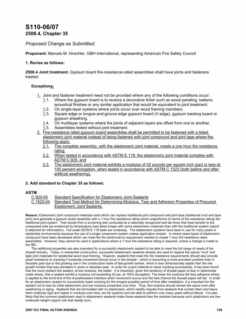
2007 ICC FINAL ACTION AGENDA 129
S110-06/07 2508.4, Chapter 35 Proposed Change as Submitted: Proponent: Marcelo M. Hirschler, GBH International, representing American Fire Safety Council 1. Revise as follows: 2508.4 Joint treatment. Gypsum board fire-resistance-rated assemblies shall have joints and fasteners treated.
Exceptions:
1. Joint and fastener treatment need not be provided where any of the following conditions occur: 1.1. Where the gypsum board is to receive a decorative finish such as wood paneling, battens,
acoustical finishes or any similar application that would be equivalent to joint treatment. 1.2. On single-layer systems where joints occur over wood framing members. 1.3. Square edge or tongue-and-groove edge gypsum board (V-edge), gypsum backing board or
gypsum sheathing. 1.4. On multilayer systems where the joints of adjacent layers are offset from one to another. 1.5. Assemblies tested without joint treatment.
2. Fire-resistance rated gypsum board assemblies shall be permitted to be fastened with a listed elastomeric joint material instead of being fastened with joint compound and joint tape where the following apply: 2.1. The complete assembly, with the elastomeric joint material, meets a one hour fire resistance
rating 2.2. When tested in accordance with ASTM E 119, the elastomeric joint material complies with
ASTM C 920, and 2.3. The elastomeric joint material exhibits a modulus of 20 pounds per square inch (psi) or less at
100 percent elongation, when tested in accordance with ASTM C 1523 (both before and after artificial weathering).
2. Add standard to Chapter 35 as follows: ASTM
C 920-05 Standard Specification for Elastomeric Joint Sealants C 1523-04 Standard Test Method for Determining Modulus, Tear and Adhesion Properties of Precured
Elastomeric Joint Sealants. Reason: Elastomeric joint compound materials exist which can replace traditional joint compound and joint tape (traditional mud and tape joint) and generate a gypsum board assembly with a 1 hour fire resistance rating which outperforms (in terms of fire resistance rating) the traditional joint system. Test results from a screening test conducted at a nationally recognized test lab show that heat transfer to the unexposed side (as evidenced by temperature rise) takes longer with some elastomeric materials than with the traditional system (report is attached for information). Full scale ASTM E 119 tests are underway. The elastomeric systems have been in use for many years in residential environments because the use of a single component system makes application simpler. In recent years types of elastomeric compound have been developed which can meet the fire performance requirement needed to create 1 hour fire resistance rated assemblies. However, they cannot be used in applications where a 1 hour fire resistance rating is required, unless a change is made to the IBC.
The additional properties are also important for a successful elastomeric sealant to be able to meet the full range of needs of the drywall industry. Today, in residential construction, successful elastomeric sealants already are used to replace the typical “mud” and tape joint materials for residential wood stud framing. However, sealants that meet the fire resistance requirements should also provide great resistance to cracking if moderate movement should occur in the drywall – which is becoming a more prevalent problem than in decades past due to the growing use in the construction trade of fast-growth lumber, which is less dimensionally stable than the old-growth lumber that was prevalent in years or decades past. In order for a joint material to resist cracking successfully, it has been found that the more resilient the sealant, at low modulus, the better. It is important, given the tendency of drywall paper to tear or delaminate under stress, that a sealant exhibit a modulus not exceeding 20 psi, at 100% elongation. The lower the modulus the less adhesive stress is applied to the bond-line of the drywall/sealant interface when movement occurs and the less chance the drywall paper will fail. In order for an elastomeric sealant to successfully resist cracking for the longest possible period of time after installation, it is important for the sealant not to lose its initial elastomeric and low modulus properties over time. Thus, the modulus should remain the same even after weathering or aging. Sealants that are formulated with no plasticizers, which readily migrate from sealants that contain them and leave them relatively rigid and higher in modulus over time, are far superior and are able to perform over many years without failure. It is also likely that the common plasticizers used in elastomeric sealants make those sealants less fire resistant because such plasticizers are low molecular weight organic oils that readily burn.

130 2007 ICC FINAL ACTION AGENDA
It has been reported that numerous drywall contractors around the US have used low modulus, high performance latex sealants for several years to seal the joints in drywall. This has been done by those contractors to prevent the kind of cracking they have otherwise experienced when they have used the traditional joint tape and mud in many situations where relatively extreme shrinkage movement has occurred in the underlying framing lumber. Now that it is possible to provide not only crack resistance but also fire resistance in such a low modulus, high performance sealant, the drywall finishing trade has a new means of providing high quality drywall finishing, with no compromise in fire safety.
The new referenced standards are: ASTM C 920, Standard Specification for Elastomeric Joint Sealants, and ASTM C 1523, Standard Test Method for Determining Modulus, Tear and Adhesion Properties of Precured Elastomeric Joint Sealants. The ASTM C 920 specification does not include a test method for modulus, which is critical for long-term performance. The ASTM C 1523 test method contains the test method for modulus as well as a weathering test method, which needs to be used to assess whether the modulus is still suitably high after aging of the assembly. ASTM C 1442 (weathering practice) and ASTM C 717 (terminology) are also attached for information. Cost Impact: The code change proposal will not increase the cost of construction. Analysis: Analysis: Results of review of the proposed standard(s) will be posted on the ICC website by August 20, 2006. Note: The following analysis was not in the Code Change Proposal book but was published in the “Errata to the 2006/2007 Proposed Changes to the International Codes and Analysis of Proposed Referenced Standards” provided at the code development hearings: Analysis: Review of proposed new standard indicated that, in the opinion of ICC staff, the standard did comply with ICC criteria for referenced standards. Committee Action: Disapproved Committee Reason: This proposal appears to be out of place in this section since this is not an exception where “joint treatment” is not required but is instead an alternate product. Additionally the text addresses gypsum board being fastened with these materials. Item 2.3 would appear to be more appropriate for determining the acceptance under the standard and does not seem to be needed within the code. The committee did recognize that this is somewhat of a “chicken or the egg” issue. This can not go into the code because there is no standard, but because the code does not address it, there is no standard developed to test it. While conceptually fine, this proposal would create confusion regarding which test and product are acceptable when testing. The proposal should be coordinated with Table 2506.2 so that a conflict does not develop with the existing code requirements for gypsum board. Assembly Action: None Individual Consideration Agenda This item is on the agenda for individual consideration because a public comment was submitted. Public Comment: Marcelo M. Hirschler, GBH International, representing Sashco, requests Approval as Modified by this public comment. Replace proposal with the following:
TABLE 2506.2 GYPSUM BOARD MATERIALS AND ACCESSORIES
MATERIAL STANDARD Accessories for gypsum board ASTM C 1047 Adhesives for fastening gypsum wallboard ASTM C 557 Elastomeric joint sealants ASTM C 920 Exterior soffit board ASTM C 931 Fiber-reinforced gypsum panels ASTM C 1278 Glass mat gypsum backing panel ASTM C 1178 Glass mat gypsum substrate ASTM C 1188 Gypsum backing board and gypsum shaftliner board ASTM C 442 Gypsum ceiling board ASTM C 1395 Gypsum sheathing ASTM C 79 Gypsum wallboard ASTM C 36 Joint reinforcing tape and compound ASTM C 474; C 475 Nails for gypsum boards ASTM C 514, F 547, F 1667 Predecorated gypsum board ASTM C 960 Steel screws ASTM C 954, C 1002 Steel studs, load bearing ASTM C 955 Steel studs, nonload bearing ASTM C 645 Standard specification for gypsum board ASTM C 1396 Testing gypsum and gypsum products ASTM C 22, C 472, C 473 Water-resistant gypsum backing board ASTM C 630

2007 ICC FINAL ACTION AGENDA 131
Add standard to Chapter 35 as follows: ASTM
C 920-05 Standard Specification for Elastomeric Joint Sealants Commenter=s Reason: As explained in the original proposal, “elastomeric joint sealant materials” exist now to seal gypsum board assemblies, replacing the traditional “joint reinforcing tape and compound”. Some of those assemblies have been tested and meet the 1 hour fire resistance rating usually considered necessary for gypsum board assemblies. In fact, tests were conducted at Southwest Research Institute on two gypsum board assemblies and they showed that the assembly tested with the joints sealed with the elastomeric joint sealant material performed at least as well as the one tested with the traditional joint reinforcing tape and compound. The assembly with the elastomeric joint sealant material achieved a 1 hour fire resistance rating (including passing the hose strean test). This comment proposes a modification to the proposal to do exactly what the technical committee tacitly recommended, namely adding a row to Table 2506.2, with the corresponding standard specification for elastomeric joint sealants (ASTM C 920). If the proposal is accepted as modified by this comment, the IBC will recognize the elastomeric joint sealant materials as an acceptable gypsum board accessory material. The use of the material will then have to comply with the appropriate requirements in other parts of the code. ICC staff analysis already indicated at the proposal stage that the standard specification (ASTM C 920) complies with the ICC criteria for referenced standards. Final Action: AS AM AMPC D
S111-06/07, Part I 2509.2 Proposed Change as Submitted: Proponent: Cliff Black, United States Gypsum Company PART I – IBC STRUCTURAL Revise as follows: 2509.2 Base for tile. Cement, fiber-cement, or glass mat gypsum backers or fiber-reinforced gypsum backers in compliance with ASTM C 1178 C 1288, C 1325, or C 1178 or C 1278, respectively, and installed in accordance with manufacturer recommendations shall be used as a base for wall tile in tub and shower areas and wall and ceiling panels in shower areas. Water resistant gypsum backing board shall be used as a base for tile in water closet compartment walls when installed in accordance with GA-216 or ASTM C 840 and manufacturer recommendations. Regular gypsum wallboard is permitted under tile or wall panels in other wall and ceiling areas when installed in accordance with GA-216 or ASTM C 840. Reason: The purpose of this proposal is to revise ASTM material standards for current provisions of the IBC & IRC.
(IBC) The code change proposal of the current code provisions represents a less restrictive and more robust cross-section of material standards appropriate for use as a backer for wall tile in tub and shower areas and wall and ceiling panels in shower areas.
The current code provisions are overly restrictive excluding an ASTM product standard which is recognized in the industry as a tile backer for use in tub and shower areas and wall and ceiling panels in shower areas. ASTM C 1278 products are engineered and manufactured specifically for interior water-resistant backing board, exterior sheathing, and interior abuse-resistant applications.
A comparison of ASTM Standard Specifications for C 1278 and C 1178 products reveals that C 1278 product physical properties meet or exceed those of C 1178.
Such a restriction within the Code has the potential for increasing the cost of construction due to narrowly defined prescriptive material reference language without acknowledging more robust performance-based material references. Substantiation: ASTM Standard Specification Comparisons – C 1278 – C 1178 ASTM C 1278: 5.1 Physical Properties of Interior Fiber-Reinforced Gypsum Panels 6.1 Physical Properties of Water-Resistant Fiber-Reinforced Gypsum Backing Panels 7.1 Physical Properties of Exterior Fiber-Reinforced Gypsum Soffıt Panels 8.1 Physical Properties of Water-Resistant Exterior Fiber-Reinforced Gypsum Sheathing Panels ASTM C 1178: 5. Physical Properties of Water-Resistant Gypsum Backing Panel Bibliography: ASTM Standard Specification Comparisons – C 1278 – C 1178 Fiberock Interior Panels Aqua-Tough Submittal Sheet – F134/rev. 1-06 – United States Gypsum Company Fiberock Sheathing Aqua-Tough Submittal Sheet – F135/rev. 1-06 – United States Gypsum Company Fiberock Aqua-Tough Tile Backerboard Submittal Sheet – F222/rev. 12-04 – United States Gypsum Company USG Web Site for the Control of Moisture and Mold – www.getmoldfacts.com/products.jsp Cost Impact: The code change proposal will not increase the cost of construction.

132 2007 ICC FINAL ACTION AGENDA
Committee Action: Disapproved Committee Reason: The committee's disapproval was based on questions that were raised about the water-resistance of products complying with ASTM C 1278. There is not a consensus that these would be equivalent to products meeting ASTM C 1178. Assembly Action: None Individual Consideration Agenda This item is on the agenda for individual consideration because a public comment was submitted. Public Comment: Cliff Black, United States Gypsum Company, requests Approval as Modified by this public comment for Part I. Replace proposal with the following: 2509.2 Base for tile. Cement Fiber-cement, fiber-cement fiber-mat reinforced cement, or glass mat gypsum backers or fiber-reinforced gypsum backers in compliance with ASTM C 1178 C 1288, C 1325, or C 1178 or C 1278, respectively, and installed in accordance with manufacturer recommendations shall be used as a base for wall tile in tub and shower areas and wall and ceiling panels in shower areas. Water resistant gypsum backing board shall be used as a base for tile in water closet compartment walls when installed in accordance with GA-216 or ASTM C 840 and manufacturer recommendations. Regular gypsum wallboard is permitted under tile or wall panels in other wall and ceiling areas when installed in accordance with GA-216 or ASTM C 840. Commenter=s Reason: The IBC Structural Code Development Committee seeks clarifying information to answer questions that were raised about the water-resistance of products complying with ASTM C 1278. The following clearly substantiates the water-resistance performance of ASTM C 1278 products and the water-resistance equivalency to ASTM C 1178 products serving as justification for approval of this proposed code change: The water-resistance physical property of ASTM C 1278 products and the water-resistance equivalency to ASTM C 1178 products is clearly substantiated through ANSI and ASTM test standards. The Wet Shear Bond of ASTM C 1278 products exceeds the minimum requirements of the Tile Council of North America per a modified ANSI 118.9 test with a value of > 50 psi saturated. The Hydrostatic Pressure Test performance of ASTM C 1278 products meets the requirements of the Tile Council of North America per ANSI 118.10 for a waterproof membrane. The test performance presented no evidence of water penetration or the formulation of droplets on the back side of the panel as required. The Water Resistance physical property of ASTM C 1278 products meet or exceed the specification for water resistance required by both ASTM C 1278 and ASTM C 1178 per ASTM C 473 (2-hour Immersion) with a value of < 5% water absorption. The 2006 IBC allows gypsum panel products to be used as a base for wall tile in tub and shower areas and wall and ceiling panels in shower areas that are in compliance with ASTM C 1178, accordingly, ASTM C 1278 products meet the intent of the code. The consensus nature of ASTM Standards validates the comparison of uniquely formulated products defined under specific ASTM Standard Specifications. Anecdotal multiyear research, begun in 1999 and completed in 2004, was carried out by Oak Ridge National Laboratory (ORNL) and Tuskegee University with funding from the U.S. Department of Energy (DOE), the Federal Emergency Management Agency (FEMA), and the Department of Housing and Urban Development (HUD) to identify and evaluate materials, systems, and methods which, when used to repair flooded building envelopes, will make a home more resistant to flood damage. The research test method was represented by a 3-day (72-hour) flooding event followed by floodwaters allowed to recede at which time the structures were left unattended permitting a drying period to begin. The following are research findings reported on the performance of specifically referenced ASTM C 1278 products:
Interior Gypsum Wall Board – “Water-resistant, fiber-reinforced gypsum interior wall panels [e.g., by USG called Aqua Tough] were tested and maintained most of their initial strength and dried out. They did not support mold growth on either surface and were easily cleaned and restored. Some other WR gypsum wall panels are likely to perform in a similar manner though they were not tested.”
The IRC Building and Energy Code Development Committee approved as modified S111-06/07, R702.3.8, R702.4.2, Part II – IRC stating the Committee Reason, “This change adds an additional new and improved ASTM material standard to this section. The modification corrects the reference to the proper ASTM standard and aligns the material descriptive code language with terminology used in the referenced ASTM material standard.” Parallel code language should be present in the IBC affording the addition of a new and improved ASTM material standard. Substantiation: ASTM Standard Specification Water Resistance Comparisons – C 1278 – C 1178 ASTM C 1278 – 6.1 Physical Properties – Water Resistance of Water-Resistant Fiber-Reinforced Gypsum Backing Panels ASTM C 1178 – 5. Physical Properties- Water Resistance of Water-Resistant Gypsum Backing Panel Bibliography: ASTM Standard Specification Water Resistance Comparisons – C 1278 – C 1178 “Technology Fact Sheet – Energy-Efficient, Flood-Damage-Resistant Home Reconstruction” – U.S. Department of Energy – Building Technology Program, November 2005 USG Web Site for the Control of Moisture and Mold – www.getmoldfacts.com/products.jsp Final Action: AS AM AMPC D

2007 ICC FINAL ACTION AGENDA 133
S111-06/07, Part II R702.3.8, R702.4.2 Proposed Change as Submitted: Proponent: Cliff Black, United States Gypsum Company PART II – IRC BUILDING/ENERGY Revise as follows: R702.3.8 Water-resistant gypsum backing board. Gypsum board used as the base or backer for adhesive application of ceramic tile or other required nonabsorbent finish material shall conform to ASTM C 630 or, C 1178 or C 1278. Use of water-resistant gypsum backing board shall be permitted on ceilings where framing spacing does not exceed 12 inches (305 mm) on center for 1/2-inch-thick (12.7 mm) or 16 inches (406 mm) for 5/8-inch-thick (15.9 mm) gypsum board. Water-resistant gypsum board shall not be installed over a vapor retarder in a shower or tub compartment. All cut or exposed edges, including those at wall intersections, shall be sealed as recommended by the manufacturer. R702.4.2 Cement, fiber-cement, and glass mat gypsum backers and fiber-reinforced gypsum backers. Cement, fiber-cement, or glass mat gypsum backers or fiber-reinforced gypsum backers in compliance with ASTM C 1288, C 1325, or C 1178 or C 1278, respectively, and installed in accordance with manufacturers’ recommendations shall be used as backers for wall tile in tub and shower areas and wall panels in shower areas. Reason: The purpose of this proposal is to revise ASTM material standards for current provisions of the IBC & IRC.
(IRC) The change to section R702.3.8 represents a less restrictive and more robust cross-section of material standards appropriate for use as water-resistant gypsum backing board.
The current code provisions are overly restrictive excluding an ASTM product standard which is recognized in the industry as a tile backer for use in tub and shower areas and wall and ceiling panels in shower areas. ASTM C 1278 products are engineered and manufactured specifically for interior water-resistant backing board, exterior sheathing, and interior abuse-resistant applications.
The change to section R702.4.2 represents a less restrictive and more robust cross-section of material standards appropriate for use as a backer for wall tile in tub and shower areas and wall panels in shower areas.
The current code provisions are overly restrictive excluding an ASTM product standard which is recognized in the industry as a water-resistant backer panel. ASTM C 1278 products are engineered and manufactured specifically for interior water-resistant backing board, exterior sheathing, and interior abuse-resistant applications.
A comparison of ASTM Standard Specifications for C 1278 and C 1178 products reveals that C 1278 product physical properties meet or exceed those of C 1178.
Such a restriction within the Code has the potential for increasing the cost of construction due to narrowly defined prescriptive material reference language without acknowledging more robust performance-based material references. Substantiation: ASTM Standard Specification Comparisons – C 1278 – C 1178 ASTM C 1278: 5.1 Physical Properties of Interior Fiber-Reinforced Gypsum Panels 6.1 Physical Properties of Water-Resistant Fiber-Reinforced Gypsum Backing Panels 7.1 Physical Properties of Exterior Fiber-Reinforced Gypsum Soffıt Panels 8.1 Physical Properties of Water-Resistant Exterior Fiber-Reinforced Gypsum Sheathing Panels ASTM C 1178: 5. Physical Properties of Water-Resistant Gypsum Backing Panel Bibliography: ASTM Standard Specification Comparisons – C 1278 – C 1178 Fiberock Interior Panels Aqua-Tough Submittal Sheet – F134/rev. 1-06 – United States Gypsum Company Fiberock Sheathing Aqua-Tough Submittal Sheet – F135/rev. 1-06 – United States Gypsum Company Fiberock Aqua-Tough Tile Backerboard Submittal Sheet – F222/rev. 12-04 – United States Gypsum Company USG Web Site for the Control of Moisture and Mold – www.getmoldfacts.com/products.jsp Cost Impact: The code change proposal will not increase the cost of construction. Committee Action: Approved as Modified Modify proposal as follows: R702.3.8 Water-resistant gypsum backing board. Gypsum board used as the base or backer for adhesive application of ceramic tile or other required nonabsorbent finish material shall conform to ASTM C 630 C 1396, C 1178 or C 1278. Use of water-resistant gypsum backing board shall be permitted on ceilings where framing spacing does not exceed 12 inches (305 mm) on center for 1/2-inch-thick

134 2007 ICC FINAL ACTION AGENDA
(12.7 mm) or 16 inches (406 mm) for 5/8-inch-thick (15.9 mm) gypsum board. Water-resistant gypsum board shall not be installed over a vapor retarder in a shower or tub compartment. All cut or exposed edges, including those at wall intersections, shall be sealed as recommended by the manufacturer. R702.4.2 Cement Fiber-cement, fiber-mat reinforced cement, glass mat gypsum backers and fiber-reinforced gypsum backers. Cement Fiber-cement, fiber-mat reinforced cement, glass mat gypsum backers or fiber-reinforced gypsum backers in compliance with ASTM C 1288, C 1325, C 1178 or C 1278, respectively, and installed in accordance with manufacturers’ recommendations shall be used as backers for wall tile in tub and shower areas and wall panels in shower areas. Committee Reason: This change adds an additional new and improved ASTM material standard to this section. The modification corrects the reference to the proper ASTM standard and aligns the material descriptive code language with the terminology used in the referenced ASTM material standard. Assembly Action: None Individual Consideration Agenda This item is on the agenda for individual consideration because a public comment was submitted. Public Comment: Michael Blades, National Gypsum Company, requests Disapproval for Part II. Commenter=s Reason: In reviewing the requested modification along with the ASTM’s referenced (ASTM C1178, C1278, C1396) It appears that the addition of products meeting ASTM C1278 is allowing the door back open to products such as water-resistant gypsum board (MR or Greenboard). The facts are that fiber-gypsum products are more than 80% gypsum and the water absorption performance (by ASTM) is exactly the same as MR/Greenboard. The surface absorption for both is 1.6 and the 2hr water absorption is 5%. The use of MR/Greenboard in wet areas was based on very specific limitations and installation instructions and the long term performance of that product was compromised by the lack of proper usage and installation. Fiber-gypsum products in wet areas are also subject to specific installation and usage. The fact that it is predominately gypsum based and does not have a protective surface coating such as glass mat gypsum backer board to prevent water contact with the gypsum core puts it in the same risk category for long term performance as MR/Greenboard. See ASTM C1278 and ASTM C1396 for surface absorption and 2hr water absorption. See USG.com for the MSDS of their fiber-gypsum product, the leading volume producer of fiber-gypsum products intended for the use of tilebacker Final Action: AS AM AMPC D