international fireball class rules
TRANSCRIPT
IFCR 2011 - Page 1
INTERNATIONAL FIREBALL
CLASS RULES 2011
© Copyright 2011 Fireball International

IFCR 2011 - Page 2
page INTERNATIONAL FIREBALL CLASS RULES - INDEX
1 GENERAL .............................................................................................................................................. 5 1.1 Objective ......................................................................................................................................... 5 1.2 Language ........................................................................................................................................ 5 1.3 Design ............................................................................................................................................. 5 1.4 Discrepancies ................................................................................................................................. 5 1.5 Rules Compliance at World and Regional Events .......................................................................... 5 1.6 Administrative Authority .................................................................................................................. 5 1.7 Emergency Rule Changes .............................................................................................................. 5 1.8 Disclaimer ....................................................................................................................................... 5
2 BUILDERS ............................................................................................................................................. 5 2.1 Professional Builders ...................................................................................................................... 5 2.2 Professional Builders’ Responsibilities ........................................................................................... 6 2.3 Additional Professional Builders ..................................................................................................... 6 2.4 Amateur Builders ............................................................................................................................ 6
3 INTERNATIONAL CLASS FEE ............................................................................................................. 6 3.1 International Class Fee Tariff, Administration ................................................................................ 6 3.2 Professionally Built Boats and Kits ................................................................................................. 7 3.3 Amateur Built Boats (from plans) .................................................................................................... 7
4 REGISTRATION .................................................................................................................................... 7 5 RECOGNITION MARKS ........................................................................................................................ 7
5.1 ISAF International Class Fee Plaque ............................................................................................. 7 5.2 Hull Identification ............................................................................................................................ 7
6 MEASUREMENT PROCEDURE ........................................................................................................... 7 6.1 Measurers ....................................................................................................................................... 7 6.2 Measurement Form ........................................................................................................................ 7 6.3 Dispensation ................................................................................................................................... 7 6.4 Re-measurement ............................................................................................................................ 8 6.5 Compliance ..................................................................................................................................... 8
7 CERTIFICATION ................................................................................................................................... 8 7.1 Administration ................................................................................................................................. 8 7.2 Owner’s Responsibility ................................................................................................................... 8 7.3 Certificate Invalidated by Change of Ownership or Corrector Weights .......................................... 8 7.4 Validity of Certificate, Membership of Class Association ............................................................... 8 7.5 Authority to Refuse or Withdraw a Certificate ................................................................................ 8
8 PROHIBITIONS ..................................................................................................................................... 8 9 HULL ...................................................................................................................................................... 9
9.1 Materials ......................................................................................................................................... 9 9.2 Construction Categories ................................................................................................................. 9 9.3 Panel Thickness ............................................................................................................................. 9 9.4 Hull Measurement Datum ............................................................................................................. 10 9.5 Length and Beam ......................................................................................................................... 10 9.6 Weight ........................................................................................................................................... 10
IFCR 2011 - Page 3
9.7 Watertight Compartments ............................................................................................................. 10 9.8 Cockpit .......................................................................................................................................... 12 9.9 Decking ......................................................................................................................................... 12 9.10 Transoms .................................................................................................................................. 13 9.11 Hull Sections ............................................................................................................................. 13 9.12 Centreboard Case ..................................................................................................................... 14 9.13 Centreboard Pivot ..................................................................................................................... 14 9.14 Mast Step .................................................................................................................................. 14 9.15 Gunwale Rubbers ..................................................................................................................... 14 9.16 Chine Deflectors........................................................................................................................ 14 9.17 Bottom Rails .............................................................................................................................. 14 9.18 Rocker ....................................................................................................................................... 14 9.19 Thwart ....................................................................................................................................... 15 9.20 Self-draining Cockpits ............................................................................................................... 15 9.21 Self Bailers ................................................................................................................................ 15
10 STAYBASE & FORE TRIANGLE ..................................................................................................... 15 10.1 Shroud Plates............................................................................................................................ 15 10.2 Fore triangle .............................................................................................................................. 16
11 MAINSHEET & SHEET LEADS ....................................................................................................... 16 11.1 Mainsheet .................................................................................................................................. 16 11.2 Sheet Leads .............................................................................................................................. 16
12 FITTINGS ......................................................................................................................................... 16 12.1 Mainsheet Hoop ........................................................................................................................ 16 12.2 Materials .................................................................................................................................... 16
13 PROJECTIONS ................................................................................................................................ 16 14 CENTREBOARD .............................................................................................................................. 17
14.1 Materials .................................................................................................................................... 17 14.2 Profile ........................................................................................................................................ 17 14.3 Weight ....................................................................................................................................... 17
15 RUDDER .......................................................................................................................................... 17 15.1 Materials .................................................................................................................................... 17 15.2 Blade Thickness, Assembly Width ............................................................................................ 18 15.3 Weight ....................................................................................................................................... 18 15.4 Attachment to Hull ..................................................................................................................... 18
16 WEAR & DAMAGE ........................................................................................................................... 18 17 MAST ............................................................................................................................................... 18
17.1 Materials .................................................................................................................................... 18 17.2 Staying and Bracing .................................................................................................................. 18 17.3 Weight ....................................................................................................................................... 18 17.4 Bent and Rotating Masts ........................................................................................................... 18 17.5 Spinnaker Halyard .................................................................................................................... 19 17.6 Mast Bands ............................................................................................................................... 19
18 BOOM .............................................................................................................................................. 19 18.1 Materials .................................................................................................................................... 19
IFCR 2011 - Page 4
18.2 Bent Booms ............................................................................................................................... 19 18.3 Section Size .............................................................................................................................. 19 18.4 Boom Band ............................................................................................................................... 19
19 SPINNAKER BOOM ......................................................................................................................... 19 19.1 Length ....................................................................................................................................... 19 19.2 Section Size .............................................................................................................................. 19 19.3 Jibstick ...................................................................................................................................... 20
20 SAILS ............................................................................................................................................... 20 20.1 Sail Measurement ..................................................................................................................... 20 20.2 Material ..................................................................................................................................... 20 20.3 Stiffening and Reinforcement .................................................................................................... 20 20.4 Mainsail ..................................................................................................................................... 20 20.5 Foresail ..................................................................................................................................... 21 20.6 Spinnaker .................................................................................................................................. 21 20.7 Class Insignia ............................................................................................................................ 22 20.8 Sail Numbers ............................................................................................................................. 22
21 CREW .............................................................................................................................................. 22 21.1 Number of crew ......................................................................................................................... 22 21.2 Competitor Clothing and Weight of Clothing ............................................................................. 22 21.3 Trapeze Harness....................................................................................................................... 22
22 TRAPEZE ......................................................................................................................................... 22 22.1 Crew Support Limitation ............................................................................................................ 22 22.2 Footloops .................................................................................................................................. 23
23 LIMITATIONS OF EQUIPMENT ...................................................................................................... 23 24 EVENT CLASSIFICATION AND ADVERTISING ............................................................................ 23 25 PROPULSION .................................................................................................................................. 23
IFCR 2011 - Page 5
1 GENERAL
INTERNATIONAL FIREBALL CLASS RULES
1.1 Objective The objective of the International Fireball Class Rules is to establish the Class as one in which all matters affecting performance are strictly controlled. Latitude is permitted to maintain interest in fitting out, maintaining and racing the boats.
1.2 Language The official language of the Class is English, and in the event of any dispute over interpretation the English text shall prevail. The definitions used in the Constitution of Fireball International shall apply to these rules.
1.3 Design International Fireball boats and kits shall be made in accordance with the design of Peter Milne and strictly in compliance with these rules.
1.4 Discrepancies In the event of discrepancy between the rules and the measurement form the matter shall be referred to the International Sailing Federation (ISAF).
1.5 Rules Compliance at World and Regional Events For major international events all boats, spars, sails and equipment shall comply with the current rules. However, boats first measured prior to January 2001 shall not be required to comply with the most recent revisions (dated December 2000) to IFCR 9.1.
1.6 Administrative Authority These rules shall be administered by the National Authority. Where there is no National Authority, or the National Authority does not wish to administer the rules, its function as stated in these rules shall be carried out by FI or its delegated representative (NCA).
1.7 Emergency Rule Changes The Executive shall be entitled to act in emergency without reference to the ISAF by issuing amendments and interpretations to the class rules provided that such decisions shall be promptly notified to the ISAF, to NCAs, and to professional builders. Amendments and interpretations shall be operative upon approval by the Chairman and Vice-Chairman of the ISAF Centreboard Boat Committee and shall be submitted for ratification to the ISAF at its next meeting.
1.8 Disclaimer The ISAF, National Authority, Fireball International (FI), National Class Associations (NCAs), Sponsor and Designer accept no responsibility in respect of these rules or any claim arising therefrom.
2 BUILDERS
2.1 Professional Builders Professional builders of the International Fireball shall be only those holding a licence under the copyright of the International Fireball to manufacture and sell International Fireball kits and/or build and sell International Fireball boats, and registered by the ISAF.
IFCR 2011 - Page 6
There shall be two categories of Builders Licence: - Category 1: Wood - Category 2: FRP & Composite
(For definitions of ‘Wood’ and ‘FRP & Composite’ Fireballs see IFCR 9.2 Construction Categories) A builder may only build Fireballs from those categories for which he is licensed.
2.2 Professional Builders’ Responsibilities Professional builders shall be responsible for supplying boats and/or kits within the measurement rules and specifications. The builder shall at his own expense correct or replace any boat or hull of his manufacture which fails to pass measurement and failure to do so may be cause for cancellation of his licence.
2.3 Additional Professional Builders Additional professional builders may be licensed (in accordance with the terms of agreement between the ISAF and the Sponsor) with the support of the National Authority and at the recommendation of FI, provided that a requirement can be shown for additional builders.
2.4 Amateur Builders 2.4.1 Building Limitation
An amateur builder shall be authorised to assemble or build not more than one International Fireball per annum. The boat shall be registered in the name of the assembler/builder and shall not be transferred to other ownership within six months of completion, without prior permission from FI.
2.4.2 Materials An amateur may build a Fireball from any combination of the materials listed in IFCR 9.2 within Category 1 and Category 2.
2.4.3 Amateur Builders Licence An amateur builder shall, before the issue of an International Class Fee Plaque, complete an official Amateur Builder’s Licence Form (ABL) undertaking that he himself will construct the boat in accordance with the rules of the International Fireball Class and that he will not employ professional boat building labour for this purpose. Note: Professional boat building labour is defined as “one who builds hulls or parts of hulls for financial gain”. Three copies of the ABL shall be completed and signed by the amateur builder and countersigned by the Issuing Authority. One copy shall be retained by the Issuing Authority, one sent to the amateur builder and the other to FI for registration.
3 INTERNATIONAL CLASS FEE
3.1 International Class Fee Tariff, Administration 3.1.1 The International Class Fee (ICF) payable in respect of professionally built boats and kits
shall be based on 3% of the UK professional licensed builder’s average retail price of the complete boat in the UK market. The ICF payable in respect of amateur built boats (from plans) shall be based on 2% of the UK professional licensed builder’s average retail price of the complete boat in the UK market. The ICF includes the Designer’s and Sponsor’s fee of 62.5%, the FI administration fee of 21% and the ISAF administration fee of 16.5% of the ICF.
3.1.2 The amount of the ICF shall be reviewed annually by the Sponsor and agreed with the ISAF.
IFCR 2011 - Page 7
3.1.3 The Sponsor shall be responsible for the collection and distribution of the ICF on the above basis.
3.2 Professionally Built Boats and Kits The ICF shall be payable by the builder whether or not the boat is subsequently measured. Payment shall be made direct to the Sponsor at his UK address. The Sponsor will issue an ISAF ICF plaque and two copies of an ICF receipt to the builder and a further copy for record purposes to FI. On sale of the boat or kit the builder shall hand the plaque and receipts (if not used to obtain a sail number) to the owner.
3.3 Amateur Built Boats (from plans) The ICF shall be payable by the Builder whether or not the boat is subsequently measured. Payment by the builder shall be made to his NCA or FI (the Issuing Authority) who will issue an ICF plaque and two copies of the ICF receipt. The Sponsor will issue ICF plaques and ICF receipts to FI for distribution to NCAs or directly supply to individual members of FI. All payments by amateur builders shall be remitted by FI to the Sponsor.
4 REGISTRATION FI shall maintain a Sail Number Register and allocate sail numbers to builders or owners on completion of an ‘International Fireball Registration Form’.
5 RECOGNITION MARKS
5.1 ISAF International Class Fee Plaque The ISAF International Class Fee plaque shall be affixed in a conspicuous place inside the cockpit of all boats on which the International Class Fee has been paid after 21st August 1970. It shall not be removed during the life of the boat.
5.2 Hull Identification The boat’s sail number shall be cut approximately 2mm deep into the thwart in figures which are not less than 25mm in height.
6 MEASUREMENT PROCEDURE
6.1 Measurers This is a one-design class. Measurement shall be carried out using these rules. Only an official measurer recognised by the National Authority (or delegated NCA), and approved by it to measure International Fireballs, shall measure a boat, its spars, sails and equipment. A measurer shall not measure a boat, spars, sails or equipment owned or built by himself, or in which he is an interested party or has a vested interest. Payment for the measurer’s services is the responsibility of the owner.
6.2 Measurement Form Two copies of the official class measurement form shall be completed and sent to the National Authority or delegated NCA or FI (the issuing Authority). The Measurer shall enter on the measurement form any deviation from the rules.
6.3 Dispensation
IFCR 2011 - Page 8
In the event of infringement of the rules both copies of the measurement form shall be sent to FI for consideration as to whether or not a Measurement Certificate shall be granted. FI shall be empowered to grant dispensation in exceptional cases subject to ratification by ISAF. A dispensation shall be recorded on both copies of the measurement form which shall be returned to the issuing Authority.
6.4 Re-measurement All boats, spars, sails and equipment shall be liable to re-measurement at the discretion of the National Authority or Race Committee, but only by an official measurer.
6.5 Compliance All new boats, spars, sails and equipment shall comply with the current rules. Old boats, spars, sails and equipment shall comply with either the current rules or with the corresponding rules applying to them at the time they were made, except that relaxations in the current rules shall apply to all boats, and that old sails shall measure under a single set of rules. Any alterations or replacements shall comply with the current rules.
7 CERTIFICATION
7.1 Administration An official class Measurement Certificate shall be issued by the National Authority or the delegated NCA or FI (the Issuing Authority) on receipt from the owner or his representative of:
1) Evidence of payment of the current class subscription 2) Two copies of a correctly completed official measurement form.
One copy of the measurement form shall be retained by the Issuing Authority and the duplicate returned to the owner.
7.2 Owner’s Responsibility It is the responsibility of the owner to ensure that his boat, spars, sails and equipment comply with the class rules and that alterations or replacements to the boat, spars, sails or equipment do not invalidate the certificate.
7.3 Certificate Invalidated by Change of Ownership or Corrector Weights Change of ownership and/or change of corrector weights shall invalidate the Measurement Certificate but shall not necessitate re-measurement. The new owner shall apply to the National Authority or the delegated NCA or FI (the Issuing Authority) for a new certificate.
7.4 Validity of Certificate, Membership of Class Association No boat shall be permitted to race as an International Fireball unless it has a valid Measurement Certificate. A certificate is valid only if the owner is a paid up member of the International Fireball Class as shall be evidenced by the display of a current membership disc displayed on the forward face of the aft bulkhead of the boat and a current receipt attached to the measurement certificate.
7.5 Authority to Refuse or Withdraw a Certificate Notwithstanding anything contained in these rules, the National Authority, or the delegated NCA, or FI (the Issuing Authority) may refuse to issue a Certificate and shall have the right to withdraw a Certificate which it has issued. FI shall have the power to withdraw a Certificate from any boat.
8 PROHIBITIONS The following are prohibited:
IFCR 2011 - Page 9
- Hydraulic and pneumatic controlled equipment - Underdeck jib furling gear - Electrical or electronic instruments - Transom scuppers - Lightening holes in thwarts - Sheets or halyards led through the watertight compartments - Materials containing carbon fibres, except as permitted by IFCR 12.
Notwithstanding the above prohibition of the use of electronic equipment, the use of entirely self-contained electronic timing devices and electronic digital compasses is permitted providing they have no data correlation capabilities.
9 HULL
9.1 Materials A Fireball hull may be made from the materials listed in Category 1 and Category 2 below. No other material shall be used, except that it is permitted to use:
- Microballoons or similar thickening agent and/or glass tape for joints between panels - Alumium or steel struts as strain members supporting the centreboard case - Any low friction material on the inside of the centreboard case - Any material for chafing pieces on the deck or in the mast partners
9.2 Construction Categories 9.2.1 Category 1: ‘Wood’
A Fireball shall be defined as a ‘wood’ Fireball, when the centre bottom panel, bilge panels, topsides, aft and bow transoms, fore and aft main bulkheads, centreboard case sides, tank sides, thwart and decking are made of solid or laminated timber, or marine plywood, the veneers of which have been bonded with water and boil proof glue.
9.2.2 Category 2: ‘FRP’ (Fibre Reinforced Plastic) and Composite A Fireball shall be defined as ‘FRP’, when the centre bottom panel, bilge panels, topsides, aft and bow transoms, fore and aft main bulkheads, centreboard case sides, tank sides and decking are made from any combination of the following: - Glass fibre or aramid fibre cloth - Polyester or epoxy resin - Rigid closed cell foam plastic or balsa wood (as a core material only) A Fireball may be defined as ‘composite’, when the centre bottom panel, bilge panels and topsides are made from those materials listed in Category 2 above, and the aft and bow transom, fore and aft main bulkheads, centreboard case sides, tank sides, thwart and deck are made from any combination of the materials listed in Category 1 and Category 2 above.
9.3 Panel Thickness 9.3.1 Category 1
For Category 1 construction materials, the thickness of the centre bottom panel, bilge panels and centreboard case sides shall be not less than 5.4mm, and the thickness of the topsides, fore and aft transoms, bulkheads, tanksides and decking shall be not less than 3.6mm.
9.3.2 Category 2 For Category 2 construction materials, the total thickness of the solid laminate (excluding
IFCR 2011 - Page 10
the core in the sandwich construction) for the centre bottom panel, bilge panels and centreboard case sides shall be not less than 1.5mm, and in the case of the topsides, fore and aft transoms, bulkheads, tanksides and decking shall not be less than 1.0mm.
9.4 Hull Measurement Datum All measurements referred to the aft transom shall be taken to the bottom of the aft face of the aft transom at its centreline: (Station ‘0’).
9.5 Length and Beam The overall length from aft transom to forward edge of bow-transom, excluding bow protection strips, shall be 4928mm ± 13mm between perpendiculars. The maximum beam excluding gunwales shall not be greater than 1359mm. The distance from the aft face of the transom to the bottom forward edge of the bow transom, measured along the bottom surface of the boat at the centreline, shall be 4802mm ± 15mm.
9.6 Weight The hull shall weigh not less than 79.4kg. The initial weighing, or any subsequent re-weighing, of the hull shall be done (after painting and/or varnishing if necessary) with the boat complete with hatch covers and toe straps and all fittings permanently fastened, bolted or screwed to the hull, but not including the centreboard, wire or rope strops, sheets or control lines. The initial weighing shall be done before the boat is launched for the first time. Any re-weighing for the purpose of changing correctors shall be done after the boat has been kept out of water, in a dry condition, with the hatch covers removed, and cover off, for at least 12 days. If a boat is found to be under weight at the time of measurement, correcting weights shall be fitted to bring the boat up to minimum permitted weight. The combined weight of the correctors shall not exceed 7.5kg. The correctors shall be bolted to the underside of the thwart in a visible position. The total weight of the correctors shall be shown on the measurement certificate. No correctors shall be removed or altered without the boat being re-weighed by an official measurer.
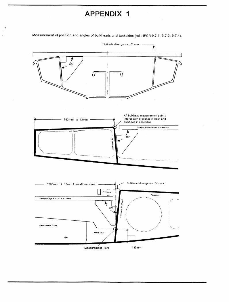
9.7 Watertight Compartments 9.7.1 The aft bulkhead shall extend across the hull to form the aft watertight compartment.
The forward face of the aft bulkhead, within the area 275mm either side of the centreline of the boat, measured at the projected intersection of the planes of the aft deck and the aft bulkhead, shall be 762mm ± 13mm from the aft transom. (See Appendix 1) The forward face of the aft bulkhead, between the point 275mm from the centreline of the boat, and the point where the aft bulkhead joins the topsides, shall be not less than 749mm and not greater than 1060mm from the aft transom.
9.7.2 The forward bulkhead shall extend across the hull to form the forward watertight compartment. The aft face of the forward bulkhead, measured at a height of 135mm above the outside of the centre bottom panel, and within 300mm either side of the centreline of the boat shall be 3200mm ± 13mm from the aft transom. (See Appendix 1) The aft face of the forward bulkhead, between the point 300mm from the centreline of the boat, and the point where the forward bulkhead joins the topsides, shall be not less than 3000mm and not greater than 3300mm from the aft transom.
9.7.3 The tanksides shall extend from the forward face of the aft bulkhead to the aft face of the forward bulkhead.
IFCR 2011 - Page 11
The distance between the inboard faces of the tank sides, at the intersection of the projected planes of the tank side and the deck, at a distance of : - 1062mm forward of the aft face of the aft transom, shall be 896 ± 13mm. - 2742mm forward of the aft face of the aft transom, shall be 935 ± 13mm.
9.7.4 The forward and aft bulkheads, and the tank sides may diverge towards the top by not more than 5 degrees. The cockpit, defined as the area bounded by the forward and aft bulkheads and the tank sides, shall be longer and wider at deck level than at floor level. (See Appendix 1)
9.7.5 Between points 1062mm and 2742mm from aft transom, the faces of the tank sides shall be flat within 8mm, both horizontally & vertically. In the area immediately under the thwart, the face of the tank side may deviate in the horizontal plane towards the hull centreline by a maximum distance of 60mm. Within 275mm of the hull centre line, the forward face of the aft bulkhead shall be flat within 8mm, both horizontally and vertically Within 300mm of the hull centre line, the aft face of the forward bulkhead shall be flat within 8mm, both horizontally and vertically.
9.7.6 The area of tanksides and bulkheads outside the measurement points described in Rule 9.7.5 above, when viewed from inside the cockpit, shall be flat or concave. The surface within this area shall be flat within 8mm when measured in any vertical plane.
9.7.7 Two spinnaker boom storage tubes, not exceeding 80mm internal diameter, may be fitted. They may only be fitted into the forward and aft watertight compartments, provided that they are sealed to prevent water entering the watertight compartments. A spinnaker launching tube may be fitted into the forward buoyancy compartment for the sole purpose of setting and stowing a spinnaker. The under-deck part of the tube shall not cross the centreline of the boat. The entire unit shall be fitted so that the forward buoyancy compartment remains watertight.
9.7.8 In addition to the self bailers allowed by Rule 9.21, and notwithstanding Rule 9.20, not more than two drainage tubes of not more than 5,000mm2 may be fitted through the aft bulkhead and the aft transom, provided they are effectively sealed to prevent water from entering the watertight compartments. The cross-section of the drainage tubes may be any shape, but the dimensions shall not exceed 75mm in any direction (horizontally or vertically). Not more than two drainage sockets may be fitted to each watertight compartment.
9.7.9 At least one, but not more than two removable hatches shall be fitted to each compartment to allow access. The opening provided shall not be less than 85mm in diameter. The hatches shall be in the cockpit sides, bulkheads or the aft transom.
9.7.10 With hatches and drain socket plugs in place, the forward and aft bulkheads, tank sides, hull and decking shall form four separate and properly sealed off watertight compartments which shall be effectively watertight when racing.
9.7.11 Except for normal fastenings and the items listed in Rule 9.7.7, 9.7.8, 9.7.9, and 9.9.4, no holes, tubes or concavities shall be made in the constructional surfaces of the watertight compartments.
9.7.12 FRP boats shall have not less than 0.08m3 rigid closed cell foam plastic buoyancy either attached to the underside of the side decks or integrally laminated within the moulded structure.
9.7.13 If required by a statutory authority or by the sailing instructions, a wet buoyancy test may be applied to the hull as follows: The boat shall be floated on its beam ends with the masthead touching the water. A load of at least 130kg shall be vertically applied to the hull. After a minimum of five minutes in this condition with one gunwale submerged the test shall be repeated for a minimum of five minutes with the other gunwale submerged. The amount of water in either side tank shall not exceed 5 litres. The hatches shall then be removed from the side tanks and the
IFCR 2011 - Page 12
test repeated. The water found in the bow and stern tanks immediately following this test shall not exceed 5 litres.
9.8 Cockpit The cockpit is defined as the area bounded by the tank sides and bulkheads; not less than 75% of this area shall be undecked. The distance between the surface of the cockpit sole and the outside of the hull, excluding the bottom rails, shall not exceed 65mm. The radius between the bulkheads and cockpit floor, and tanksides and cockpit floor, shall not exceed 19mm.
9.9 Decking 9.9.1 The decking shall form the top of the buoyancy compartments. 9.9.2 Foredeck and aft deck
Measured down the centreline of the forward bulkhead the height of the crown of the foredeck above the outside of the centre bottom panel shall be 539mm ± 13mm. The foredeck centreline, from the crown of the forward bulkhead to the crown of the forward transom shall be a convex curve. Measured down the centreline of the aft bulkhead the height of the crown of the aft deck above the outside of the centre bottom panel shall be 371mm ± 13mm. The aft deck centreline from the crown of the aft bulkhead to the crown of the aft transom shall not deviate from a straight line by more than 3mm. The radius between the aft deck and aft bulkhead, and the foredeck and forward bulkhead, shall not exceed 19mm. Except for the channels described in Rule 9.10.4 permitted in the aft deck there shall be no concavity in excess of 3mm in the surfaces of the foredeck or aft deck.
9.9.3 Side decks The height, measured above the outside of the bottom panel, of the upper surfaces of the side decks where the side tanks join the bilge panels, shall not be less than 412mm at the point 2742mm forward of the aft transom, and not less than 305mm at the point 1062mm forward of the aft transom. Between these measurement points the upper surface of the side tanks shall not be below a straight line. The radius between the side decks and tank sides shall not exceed 19mm. When measured athwartships the tops of the side tanks shall not deviate from a straight line by more than 3mm. Except for the channels described in Rule 9.9.4 there shall be no concavity in excess of 3mm in the surfaces of the sidedecks
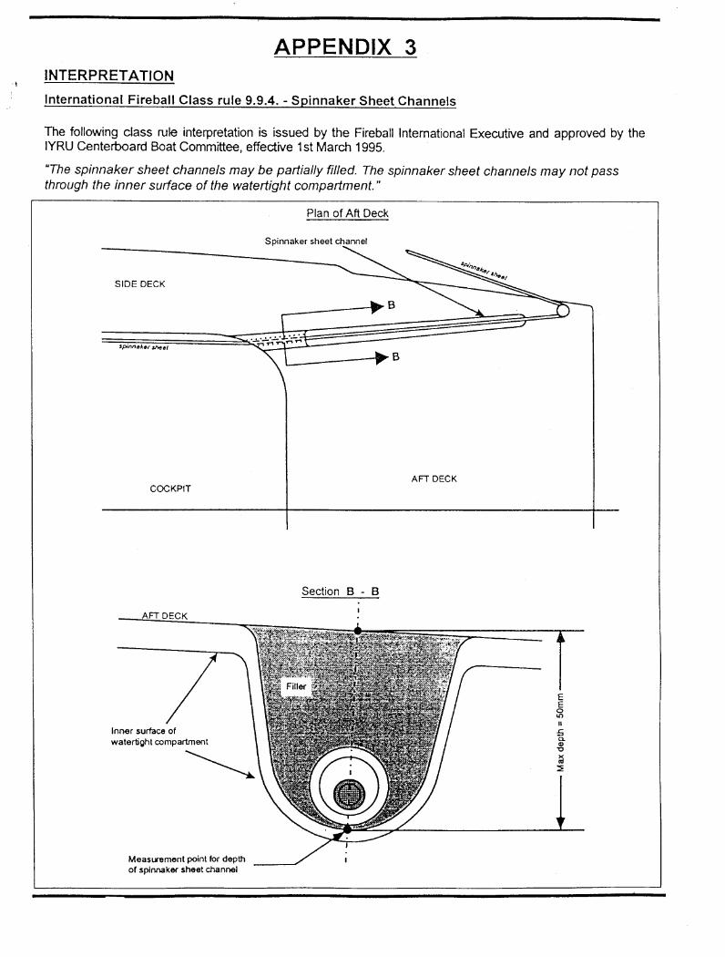
9.9.4 Spinnaker Sheet Channels An FRP boat, as defined by Rule 9.2.2, may have two straight channels for the sole purpose of leading the spinnaker sheet from the inside of the cockpit to the spinnaker sheet fairleads mounted on the aft deck. These channels, which shall be integrally moulded into the deck, aft bulkhead and side tank structure and comply with IFCR 9.3, may be not more than 50mm deep when measured from the plane of the aft deck and not more than 50mm wide when measured at right angles to the centreline of the boat; their junction with the deck, bulkhead or tankside may have a maximum radius of 10mm. The spinnaker sheet channels may extend from a point 160mm from the aft face of the aft transom to a point 1062mm from the aft transom, and may be recessed into the aft bulkhead, the aft deck, and the side tanks providing that their outboard edges are no further than 448mm from the centreline at a distance of 1062mm from the aft transom. No part of the spinnaker sheet channels, or their radiused edges, may extend further
IFCR 2011 - Page 13
outboard than the sheerline.
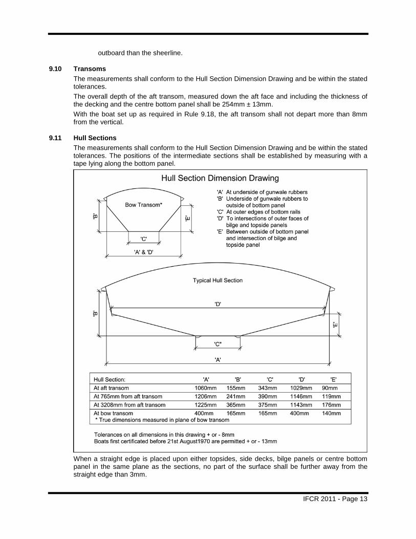
9.10 Transoms The measurements shall conform to the Hull Section Dimension Drawing and be within the stated tolerances. The overall depth of the aft transom, measured down the aft face and including the thickness of the decking and the centre bottom panel shall be 254mm ± 13mm. With the boat set up as required in Rule 9.18, the aft transom shall not depart more than 8mm from the vertical.
9.11 Hull Sections The measurements shall conform to the Hull Section Dimension Drawing and be within the stated tolerances. The positions of the intermediate sections shall be established by measuring with a tape lying along the bottom panel.
When a straight edge is placed upon either topsides, side decks, bilge panels or centre bottom panel in the same plane as the sections, no part of the surface shall be further away from the straight edge than 3mm.
IFCR 2011 - Page 14
9.12 Centreboard Case No part of the centreboard case or the centreline structure above the cockpit sole shall exceed 320mm in width, except for struts, knees or strain members, the total of which shall not exceed three on each side of the centreboard case. The fore and aft dimension of any strut, knee or strain member shall not exceed 50mm when viewed in plan. The slot shall not exceed 30mm in width. The sides of the slot opening in the bottom of the boat may have a radius. Slot closure strips are permitted.
9.13 Centreboard Pivot The pivot shall be centred 70mm±7mm above the outside of the centre bottom panel, and 2698mm ± 26mm from the aft transom measured along the bottom panel. The pivot shall be fitted passing through the centreboard pivot hole.
9.14 Mast Step The mast shall be stepped on top of the spur at the forward end of the centreboard case. The depth of the spur above the outside of the centre bottom panel shall be at least 135mm. The height of the heel of the mast above the outside of the centre bottom panel shall not exceed 165mm, tenon excluded, when the mast is positioned 75mm from the forward bulkhead.
9.15 Gunwale Rubbers The outer edges of these shall not project more than 38mm nor less than 6mm from the outside of the hull when measured at 90° to the face of the topsides. The gunwale rubbers shall extend the full length of the gunwales but may be rounded off at the extreme ends. The depth of the gunwale rubbers at the face of the topsides shall not exceed 30mm nor be less than 15mm.
9.16 Chine Deflectors These shall be triangular in section with outboard face flush with the topside and the upper face flush with the surface of the bilge panel. The deflectors shall extend forward of the aft transom for at least 3860mm. The dimensions shall be within the limits stated below, except that for a distance not exceeding 305mm from the forward end, the deflectors may be faired into the hull. Width of upper face 32mm ± 2mm. Overall depth measured at 90° to the plane of the bilge panel: 6mm minimum, 11mm maximum.
9.17 Bottom Rails The outboard face of each rail shall be at 90° to the plane of the centre bottom panel and lie on the knuckle formed between the centre bottom panel and each bilge panel. The bottom rails shall extend forward of the aft transom at least 2820mm. The forward 102mm may be faired into the bottom of the hull. The bottom rails shall be 10mm deep at the outboard edges and 32mm wide. Both these dimensions shall have tolerance of ± 2mm. The unfaired length of the bottom rails shall have level bottom surfaces to which the flat surfaces of the protection strips shall be fastened. The protection strips shall be metal or plastic or FRP, and shall be a minimum of 3mm and a maximum of 8mm deep, and a minimum of 6mm and a maximum of 14mm wide. For Category 2 hulls, the protection strips as prescribed above, may be incorporated within the hull moulding provided that the bottom rails and integrated protection strips are constructed from glass fibre or aramid fibre cloth, and filled with resin and microballoons or similar thickening agent.
9.18 Rocker With the boat upside down and the transoms supported on blocks of equal thickness on a level
IFCR 2011 - Page 15
surface, a base line shall be set up directly above the centreline. One end shall be 305mm above station ‘O’. The other end shall be 407mm above a point 4760mm from the aft transom (station ‘O’) measured round the bottom panel. In this rule, all measurements from the aft transom (station ‘O’) shall be measured along the bottom surface of the boat at centreline. Station Distance from aft transom Distance from baseline to centre bottom panel A 765mm 231 ± 8mm B 1580mm 164 ± 8mm C 2390mm 125 ± 8mm D 3208mm 137 ± 8mm E 3975mm 229 ± 8mm A line pulled taut between the ends of the centre bottom panel shall in no place be more than 3mm from the skin. An area of the bottom panel 300mm aft of the lower edge of the forward transom and 300mm forward of the lower edge of the aft transom shall be flat or a convex curve when measured parallel to the centreline of the boat. In addition, a straight edge 300mm long placed on the bottom panel parallel to the fore and aft centreline of the boat and with its forward end opposite the lower edge of the forward transom or its aft end opposite the lower edge of the aft transom, shall be nowhere more than 2mm from the surface of the bottom panel.
9.19 Thwart The thwart shall be of solid timber made from wood or FRP as listed in Rule 9.2, and shall be 114mm ± 6mm wide and 16mm ± 2mm thick. The radius of the edges of the thwart shall not exceed 16mm. The thwart shall be fitted with its forward edge 2134mm ± 13mm from the aft transom. The height of the top of the thwart above the outside of the centre bottom panel, or its extended plane, shall nowhere be less than 256mm. Flanges with their outer faces extending downwards from the fore and aft edges of the thwart may be fitted to a maximum depth of 45mm measured from the bottom face of the thwart. If fitted these flanges shall be 16mm ± 2mm thick and may deviate from the vertical by a maximum of 5 degrees. The joint between these thwart flanges and the tankside may have a maximum radius of 90mm.
9.20 Self-draining Cockpits No surface within the hull below the permitted deck shall divert water overboard or into the centreboard case.
9.21 Self Bailers Two self bailers may be fitted. The total effective area of the bailing outlets shall not exceed 1510mm2.
10 STAYBASE & FORE TRIANGLE
10.1 Shroud Plates The lower end of the shrouds and their associated fittings shall be attached to the shroud plates which shall be fixed to the outside of the hull and have attachment holes not exceeding 10mm in diameter. The centres of these holes shall be 2667mm ±26mm forward of the aft transom. The distance between the shroud plates at the sheer shall be 1324mm ± 13mm. The shroud plates shall not be recessed or faired into the plane of the hull’s surface.
IFCR 2011 - Page 16
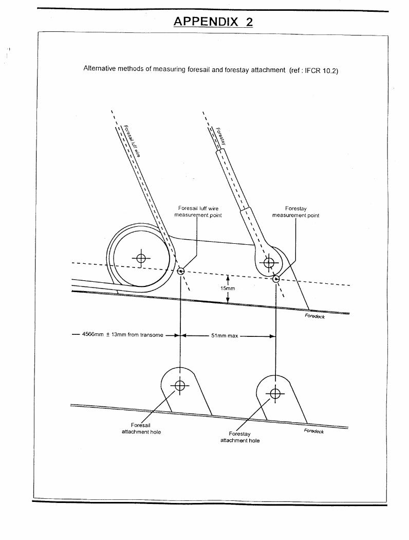
10.2 Fore triangle The attachment hole for the foresail luff wire, or the extension of the centre of the foresail luff wire, when rigged in it’s normal position and measured at a point 15mm above the deck, shall be 4566 ± 13mm forward of the aft transom and within 20mm of the fore and aft centreline of the foredeck. (See Appendix 2) The attachment hole for the forestay, or the extension of the centre of the forestay, when rigged in it’s normal position and measured at a point 15mm above the deck, shall be not more than 51mm forward of the attachment hole for the foresail luff wire and within 20mm of the fore and aft centreline of the foredeck.
11 MAINSHEET & SHEET LEADS
11.1 Mainsheet The points of attachment or lead of the standing part of the mainsheet to the boat, whether fixed or moveable, shall be contained within the areas defined below or the vertical extensions thereof:
1) The area contained by the forward face of the aft bulkhead, the forward edge of the thwart and the inboard faces of the tanksides.
2) The area contained by the forward face of the aft bulkhead, the outer edges of the gunwale rubbers and the imaginary line 25mm aft of and parallel to the aft face of the aft transom.
11.2 Sheet Leads No fixed part of the foresail or spinnaker sheet leads shall project beyond the outside edge of the gunwale rubbers when viewed in plan. The control lines for any floating (non-fixed) sheet leads shall run through or be attached to a fixed fairlead or block complying with the limitations for fixed leads except where such a control line is led permanently through the end fitting on a spinnaker pole.
12 FITTINGS
12.1 Mainsheet Hoop A main sheet hoop which shall be removable for inspection and weigh not more than 1.5kg may be fitted and, if fitted, shall be included in the hull weight. The weight shall be officially stamped on it.
12.2 Materials Notwithstanding Rule 8, (PROHIBITIONS), equipment listed below made from resins containing short strand fibres of any material, may be used:
- fixed fittings directly attached to the hull. - pulley blocks.
13 PROJECTIONS Apart from bow projection strips of maximum section 5mm, fore and aft, and 50mm deep, stern projection strips of maximum section 5mm fore and aft and 50mm deep, fitted at deck level, chine deflectors, rudder fittings, horse, shroud plates, bottom rail protection strips, centreboard slot closure strip and protection strip, self bailers, normal transom drain sockets, gunwale rubbers, hatch covers in transom, deck projecting not more than 15mm beyond the aft transom, no other form of projection or deflector shall be fitted to or through the outside of the hull shell.
IFCR 2011 - Page 17
14 CENTREBOARD
14.1 Materials The centreboard shall be of solid timber, laminated timber, solid plywood, fibre reinforced plastic or a combination of these materials. Regardless of the material used, the board shall float, even with holes drilled through the core. A protective strip, of maximum size 10mm x 10mm cross section may be applied to any edge of the centreboard.
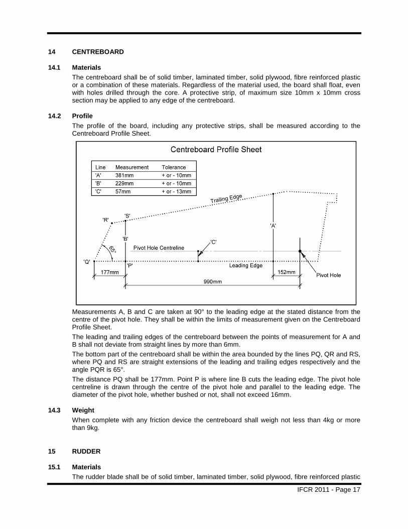
14.2 Profile The profile of the board, including any protective strips, shall be measured according to the Centreboard Profile Sheet.
Measurements A, B and C are taken at 90° to the leading edge at the stated distance from the centre of the pivot hole. They shall be within the limits of measurement given on the Centreboard Profile Sheet. The leading and trailing edges of the centreboard between the points of measurement for A and B shall not deviate from straight lines by more than 6mm. The bottom part of the centreboard shall be within the area bounded by the lines PQ, QR and RS, where PQ and RS are straight extensions of the leading and trailing edges respectively and the angle PQR is 65°. The distance PQ shall be 177mm. Point P is where line B cuts the leading edge. The pivot hole centreline is drawn through the centre of the pivot hole and parallel to the leading edge. The diameter of the pivot hole, whether bushed or not, shall not exceed 16mm.
14.3 Weight When complete with any friction device the centreboard shall weigh not less than 4kg or more than 9kg.
15 RUDDER
15.1 Materials The rudder blade shall be of solid timber, laminated timber, solid plywood, fibre reinforced plastic
IFCR 2011 - Page 18
or a combination of these materials. Regardless of the materials used, the blade shall float, even with holes drilled through the core. Protective strips may be applied to the edges.
15.2 Blade Thickness, Assembly Width The rudder blade below the waterline shall not exceed a thickness of 25mm complete with its protective coating. Except for the tiller extension, the assembly and fittings shall not exceed 100mm in transverse width.
15.3 Weight The weight of the complete rudder assembly including blade, fittings, tiller and extension, shall not be less than 3.0kg.
15.4 Attachment to Hull The rudder shall be fitted to the transom in such a manner that it will not part company with the boat during a capsize.
16 WEAR & DAMAGE On a check re-measurement at a Regatta the Race Committee or Jury may allow additional tolerance for obvious wear or damage on wooden or FRP parts.
17 MAST
17.1 Materials The mast shall be aluminium alloy, steel or wood.
17.2 Staying and Bracing The mast shall be stayed by one pair of shrouds and one forestay only. The mast may be braced by either one pair of spreaders extending to the shrouds or one pair of diamond wires. The mast shall be free from staying or bracing above a point 5166mm from the heel, tenon excluded. A device, the sole purpose of which is the control of the fore and aft movement of the mast, may be fixed below the top of the lower measurement band. Lower shrouds are not permitted.
17.3 Weight The mast tip weight shall be taken with the mast horizontal and supported at a point 50mm from the heel, tenon excluded. The weight shall be taken at a point 6735mm from the heel, tenon excluded. During weighing the halyards (including all shackles, swivels, etc., not permanently attached to the sails) shall be fully hoisted so that their eyes are hard against the upper halyard sheaves or leads. The lower ends of halyards, shrouds, forestay and trapeze wires (excluding any fitting for altering the tension of standing rigging which weighs more than 0.25kg) shall be stretched along the mast and secured to it as close to the heel as possible; any rigging extending beyond the heel shall be supported and not weighed. Rigging for the spinnaker pole uphaul/downhaul and any wire strops shall be secured along the mast in their normal positions. The tip weight in this condition shall not be less than 4.00kg.
17.4 Bent and Rotating Masts Permanently bent or rotating masts are prohibited. A permanent set of up to 40mm due to deformation is permitted in the line of the aft edge of the mast from upper band to heel when rigged in the boat without tension in the shrouds or bracing.
IFCR 2011 - Page 19
17.5 Spinnaker Halyard The bearing point of the eye, tube or sheave which supports the spinnaker halyard shall not be higher than 125mm above the bottom edge of the middle mast band, nor extend more than 75mm from the forward face of the mast.
17.6 Mast Bands 17.6.1 The mast shall carry three indelibly marked bands of a colour strongly contrasting with
the colour of the mast. These bands shall not be less than 10mm in width. 17.6.2 The top of the lower band shall not be more than 1029mm above the heel of the mast,
tenon excluded. When racing the top of the boom shall not come below the top of the lower band.
17.6.3 The lower edge of the middle band shall not be more than 5086mm nor less than 5074mm above the heel of the mast, tenon excluded. The line of the luff of the foresail, when extended, shall not meet the forward side of the mast above this height. The points where the lines of the shrouds and of the forestay when extended meet the mast shall be within 80mm of the lower edge of the middle band.
17.6.4 The lower edge of the upper band shall not be more than 5715mm above the top edge of the lower band. When racing, no part of the mainsail shall extend above the lower edge of this band.
18 BOOM
18.1 Materials The boom shall be aluminium alloy, steel or wood, and not permanently bent.
18.2 Bent Booms Permanently bent booms are prohibited. A permanent set of up to 20mm due to deformation is permitted in the line of the top of the boom.
18.3 Section Size The boom shall pass through a ring of 105mm diameter. Fixed fittings serving solely to attach sheets, outhaul, kicking strap and spinnaker pole to the boom are excluded from having to pass through the 105mm ring.
18.4 Boom Band The boom shall carry an indelibly marked band of a colour strongly contrasting with the colour of the boom. The band shall not be less than 10mm wide. With the boom fitted on the gooseneck and at right angles to the mast, the distance between the downward projection of the aft edge of the mast, disregarding local projection or cut outs, and the forward edge of the band shall not exceed 2845mm. When racing, no part of the mainsail shall extend aft of the forward edge of this band.
19 SPINNAKER BOOM
19.1 Length When fixed to the mast the distance between the extreme outboard end, including fittings, and the nearest point of the mast at the mast fixing attachment, shall not exceed 2025mm.
19.2 Section Size
IFCR 2011 - Page 20
The spinnaker boom, complete with fittings, shall be capable of passing through a ring 64mm in diameter.
19.3 Jibstick 19.3.1 The spinnaker boom may be used as a jibstick.
20 SAILS The wording of this rule has only been adjusted to comply with ISAF terminolgy.
20.1 Sail Measurement 20.1.1 Each sail shall be approved by an official measurer who shall sign and date a mainsail or
foresail near the tack and a spinnaker near the head. Details (maker and number) shall be entered on the Measurement Certificate. When the owner already has a certificate this shall be done by an official measurer.
20.1.2 All Sails shall be measured in a dry state on a flat surface with just sufficient tension to remove wrinkles across the line of the measurement being taken. Battens in the leech of the mainsail shall be removed.
20.2 Material Sails shall be single ply soft sails made of woven or laminated ply.
20.3 Stiffening and Reinforcement 20.3.1 Primary reinforcement of woven or laminated ply is permitted only at the sail corner
measurement points and at the Cunningham eye. This primary reinforcement shall be within a distance from the relevant sail corner measurement point or Cunningham eye of: Mainsail - 320mm, Foresail - 280mm, Spinnaker - 280mm.
20.3.2 Secondary reinforcement of woven or laminated ply shall be within a distance from the sail corner measurement point or Cunningham eye of: Mainsail - 960mm, Foresail - 840mm, Spinnaker - 840mm. Stiffening of the secondary reinforcement by the addition of bonding agents, “close stitching” (consisting of parallel, or nearly parallel, lines of stitching, which are 40mm apart or less and are not sewing the edges of reinforcing patches) or otherwise is not permitted.
20.3.3 Tabling at the edges of the sail is permitted provided it is not stiffened. Tabling width shall be uniform with a tolerance of ± 5mm and extend the full length of the luff, leech or foot, except for a headsail when any extension of tabling beyond an area of corner reinforcement may be tapered towards the outside edge of the sail for the last 100mm.
20.3.4 Chafing patches shall not be larger than is necessary to resist the chafe but in any case shall not exceed the following dimensions in any direction: Mainsail - 960mm, Foresail - 840mm.
20.3.5 Flutter patches shall not exceed the following dimensions in any direction: Mainsail - 105mm, Foresail - 75mm, Spinnaker - 75mm.
20.3.6 Secondary reinforcement at a spinnaker recovery point is permitted. 20.3.7 Batten pocket patches shall not exceed 320mm in any direction.
20.4 Mainsail 20.4.1 The leech length shall not exceed 6350mm. 20.4.2 The quarter width shall not exceed 2550mm.
The half width shall not exceed 1940mm. The three-quarter width shall not exceed 1140mm.
20.4.3 The top width shall not exceed 180mm. The headboard shall not exceed 160mm in
IFCR 2011 - Page 21
depth. 20.4.4 The number of battens shall be four: The top batten shall not exceed 1170mm in length
and shall extend to the mast. The distance of the top of the upper batten at the leech from the head point shall not be less than 1280mm. The bottom batten shall not exceed 690mm in length and shall nowhere be less than 800mm from the foot. The two intermediate battens shall not exceed 840mm in length. The battens shall not exceed 50mm in width.
20.4.5 A maximum of two window opening(s) may be fitted. The total window are shall not exceed 0.28m2, nor shall any opening be less than 150mm from any edge of the sail.
20.4.6 A double luff sail or loose footed sail is prohibited. 20.4.7 No reefing points are permitted. Reefing points are defined cringles or attachments to the
mainsail, the purpose of which may be to assist in reducing the effective area of the sail. In addition to the normal tack eyelet, one other cringle, eyelet, pulley or attachment, is allowed within a 400mm radius of the tack.
20.5 Foresail 20.5.1 The foresail shall be a three cornered sail. A convex curve is permitted in the foot, but not
in the leech. Only one cringle, eye or ring is permitted in the vicinity of the clew. 20.5.2 The luff length shall not exceed 4320mm. 20.5.3 The luff perpendicular shall not exceed 1525mm. 20.5.4 The foot median shall not exceed 155mm plus the mean of the luff length and the leech
length. 20.5.5 No battens or stiffening, other than primary reinforcement and secondary reinforcement,
are permitted. 20.5.6 A maximum of two window opening(s) may be fitted. The total window area shall not
exceed 0.28m2, nor shall any opening be less than 150mm from any edge of the sail. 20.5.7 The luff of the foresail shall not enclose the forestay. 20.5.8 The top width shall not exceed 40mm. 20.5.9 RRS 50.4 shall not apply.
20.6 Spinnaker 20.6.1 The spinnaker shall be a symmetrical three cornered sail. No headboard, battens or
stiffening, other than primary reinforcement and secondary reinforcement, are permitted. 20.6.2 When measuring, the sail shall be folded in half with the clew points laid on top of each
other. 20.6.3 The distance between the head point and the clew points, measured round the edge of
the sail, shall not exceed 4350mm. (Note: The reference to length of leeches has been removed, since it may be confused with ISAF’s leech length, which is a straight line between the head point and the clew points. Eventually, the rule will have to comply with ISAF’s leech length definition, but that would require a change to the actual measurement, so this can be considered a transitory wording.)
20.6.4 The foot median shall not exceed 5100mm. 20.6.5 The distance between the mid foot point and the clew points, measured round the foot of
the sail, shall not exceed 1500mm. (Note: The reference to half width has been removed, since it may be confused with ISAF’s half width, which is the distance between the half leech points. Eventually, the rule will have to comply with ISAF’s foot length definition, but that would require a change to the actual measurement, so this can be considered a transitory wording.)
20.6.6 At no point shall the distance between the leeches and the centre fold, when taken at right angles to the centre fold, exceed 1800mm. (Note: The reference to half width has been removed, since it may be confused with ISAF’s half width, which is the distance
IFCR 2011 - Page 22
between the half leech points. Eventually, the rule will have to comply with ISAF’s quarter width, half width and three-quarter width definitions, but that would require a change to the actual measurement, so this can be considered a transitory wording.)
20.6.7 The half width shall not be less than 3000mm. 20.6.8 Only one spinnaker may be carried in the boat.
20.7 Class Insignia The International Fireball Class insignia shall be a red disc 510mm ± 13mm in diameter placed back to back on the two sides of the mainsail above the sail numbers.
20.8 Sail Numbers 20.8.1 Every boat shall carry on each side of the mainsail:
a) The class insignia - the size and position as described in IFCR 20.7. b) The national letters (see RRS Appendix G for appropriate national letters). c) The sail number - issued by Fl - as referred to in IFCR 4 and IFCR 5.2.
20.8.2 The national letters and the sail numbers shall be positioned on the mainsail above an imaginary line projecting at right angles to the luff from a point one-third of the distance, measured from the tack to the head of the sail. The national letters and the sail numbers shall be placed at different heights on the two sides of the sail. The starboard side numbers shall be uppermost.
20.8.3 The sail numbers shall be carried on the leeward (forward) side of the spinnaker and may be placed on both sides.
20.8.4 The national letters and sail numbers shall be in capital letters and Arabic numerals and shall be clearly legible.
20.8.5 The letters and numbers shall be of the following minimum dimensions: Height: 300mm min. Width: 200mm min. (excl. no.1 and letter “I”) Thickness: 40mm min. Space between adjoining letters and numerals: 60mm min.
21 CREW
21.1 Number of crew The boat shall be raced by a crew of two persons.
21.2 Competitor Clothing and Weight of Clothing A competitor’s clothing shall not weigh more than 8 kilograms, when weighted as determined by RRS Appendix H. This weight excludes a trapeze harness and clothing (including footwear) worn only below the knee.
21.3 Trapeze Harness A trapeze belt or harness shall only be worn by one crew member. A trapeze belt or harness shall have positive buoyancy and shall weigh no more than 3.5kg weighed as determined by RRS Appendix H. This rule changes RRS 49.1.
22 TRAPEZE
22.1 Crew Support Limitation
IFCR 2011 - Page 23
Apart from toestraps, which shall be contained within the cockpit area, and a trapeze suspended from the hounds which shall be used to support one person only, no other means may be used to support the helmsman or crew outboard while racing.
22.2 Footloops One flexible footloop, not exceeding 300mm in overall length, may be fitted to the gunwale on each side of the boat to support the crew. These loops shall not be used to support the crew’s foot beyond the edge of the gunwale while racing.
23 LIMITATIONS OF EQUIPMENT The following rule shall apply to International Championships only and shall be specified in the Sailing Instructions. “In any one series a boat shall have not more than one mast, boom, centreboard and rudder and two suits of sails. These items shall be declared to the Race Committee before the start of the series. In the event of serious damage the Race Committee may authorise the use of a replacement”.
24 EVENT CLASSIFICATION AND ADVERTISING In World and Continental events a competitor may be required or induced to display advertising on a yacht, clothing or equipment.
25 PROPULSION The following rule changes RRS 42 and shall only apply to World and Continental Championships and other events as agreed with Fireball International only if so specified in the Notice of Race and Sailing Instructions. RRS 42 is changed to insert at new rule, RRS 42.3(i): "42.3(i) When the wind speed is clearly over 12 knots across the course, the Race Committee may signal in accordance with RRS Appendix P5 that pumping, rocking and ooching are permitted after the starting signal. This changes RRS 42.2(a), 42.2 (b) and 42.2(c)." Effective : December 10th, 2011 Previous Issues : January 1st, 2006 January 1st, 2003 December 30th, 2000 January 1st, 1997 January 1st, 1995 February 1st, 1994 May 13th, 1993 March 1st, 1993