international iec standard 61386-1
TRANSCRIPT

Conduit systems for electrical installations –
Part 1: General requirements
Reference number IEC 61386-1:1996(E)
INTERNATIONAL STANDARD
IEC61386-1
First edition1996-11
This English-language version is derived from the original bilingual publication by leaving out all French-language pages. Missing page numbers correspond to the French-language pages.
Publication numbering
As from 1 January 1997 all IEC publications are issued with a designation in the 60000 series. For example, IEC 34-1 is now referred to as IEC 60034-1.
Consolidated editions
The IEC is now publishing consolidated versions of its publications. For example, edition numbers 1.0, 1.1 and 1.2 refer, respectively, to the base publication, the base publication incorporating amendment 1 and the base publication incorporating amendments 1 and 2.
Further information on IEC publications
The technical content of IEC publications is kept under constant review by the IEC, thus ensuring that the content reflects current technology. Information relating to this publication, including its validity, is available in the IEC Catalogue of publications (see below) in addition to new editions, amendments and corrigenda. Information on the subjects under consideration and work in progress undertaken by the technical committee which has prepared this publication, as well as the list of publications issued, is also available from the following:
• IEC Web Site (www.iec.ch)
• Catalogue of IEC publications
The on-line catalogue on the IEC web site (www.iec.ch/searchpub) enables you to search by a variety of criteria including text searches, technical committees and date of publication. On-line information is also available on recently issued publications, withdrawn and replaced publications, as well as corrigenda.
• IEC Just Published
This summary of recently issued publications (www.iec.ch/online_news/ justpub) is also available by email. Please contact the Customer Service Centre (see below) for further information.
• Customer Service Centre
If you have any questions regarding this publication or need further assistance, please contact the Customer Service Centre:
Email: [email protected] Tel: +41 22 919 02 11 Fax: +41 22 919 03 00

Conduit systems for electrical installations –
Part 1: General requirements
For price, see current catalogue
IEC 1996 Copyright - all rights reserved
No part of this publication may be reproduced or utilized in any form or by any means, electronic or mechanical, including photocopying and microfilm, without permission in writing from the publisher.
International Electrotechnical Commission, 3, rue de Varembé, PO Box 131, CH-1211 Geneva 20, SwitzerlandTelephone: +41 22 919 02 11 Telefax: +41 22 919 03 00 E-mail: [email protected] Web: www.iec.ch
INTERNATIONAL STANDARD
IEC61386-1
First edition1996-11
V Commission Electrotechnique InternationaleInternational Electrotechnical CommissionМеждународная Электротехническая Комиссия
PRICE CODE

1386-1 IEC:1996 – 3 –
CONTENTS
Page
FOREWORD ................................................................................................................... 5
Clause
1 Scope .................................................................................................................... 7
2 Normative references ............................................................................................. 7
3 Definitions.............................................................................................................. 7
4 General requirements............................................................................................. 11
5 General conditions for tests .................................................................................... 11
6 Classification.......................................................................................................... 13
7 Marking and documentation.................................................................................... 17
8 Dimensions ............................................................................................................ 19
9 Construction........................................................................................................... 19
10 Mechanical properties ............................................................................................ 23
11 Electrical properties................................................................................................ 31
12 Thermal properties ................................................................................................. 35
13 Fire effects............................................................................................................. 41
14 External influences ................................................................................................. 41
15 Electromagnetic compatibility ................................................................................. 45
Figures
1 Arrangement for compression test .......................................................................... 46
2 Impact test apparatus ............................................................................................. 47
3 Assembly of conduit and conduit fittings for bonding test ......................................... 48
4 Arrangement for insulation resistance and electric strength test – Rigid conduit....... 49
5 Arrangement for insulation resistance and electric strength test – Pliableand flexible conduit ................................................................................................ 50
6 Enclosure for burning test....................................................................................... 51
7 Arrangement for burning test .................................................................................. 52
8 Test apparatus for burning resistance to heat ......................................................... 53
Annex A – Classification coding for conduit systems ........................................................ 63

1386-1 IEC:1996 – 5 –
INTERNATIONAL ELECTROTECHNICAL COMMISSION__________
CONDUIT SYSTEMS FOR ELECTRICAL INSTALLATIONS –
Part 1: General requirements
FOREWORD
1) The IEC (International Electrotechnical Commission) is a worldwide organization for standardizationcomprising all national electrotechnical committees (IEC National Committees). The object of the IEC is topromote international co-operation on all questions concerning standardization in the electrical and electronicfields. To this end and in addition to other activities, the IEC publishes International Standards. Theirpreparation is entrusted to technical committees; any IEC National Committee interested in the subject dealtwith may participate in this preparatory work. International, governmental and non-governmental organizationsliaising with the IEC also participate in this preparation. The IEC collaborates closely with the InternationalOrganization for Standardization (ISO) in accordance with conditions determined by agreement between thetwo organizations.
2) The formal decisions or agreements of the IEC on technical matters express, as nearly as possible, aninternational consensus of opinion on the relevant subjects since each technical committee has representationfrom all interested National Committees.
3) The documents produced have the form of recommendations for international use and are published in theform of standards, technical reports or guides and they are accepted by the National Committees in thatsense.
4) In order to promote international unification, IEC National Committees undertake to apply IEC InternationalStandards transparently to the maximum extent possible in their national and regional standards. Anydivergence between the IEC Standard and the corresponding national or regional standard shall be clearlyindicated in the latter.
5) The IEC provides no marking procedure to indicate its approval and cannot be rendered responsible for anyequipment declared to be in conformity with one of its standards.
6) Attention is drawn to the possibility that some of the elements of this International Standard may be thesubject of patent rights. The IEC shall not be held responsible for identifying any or all such patent rights.
International Standard IEC 1386-1 has been prepared by subcommittee 23A: Cablemanagement systems, of IEC technical committee 23: Electrical accessories.
The text of this standard is based on the following documents:
FDIS Report on voting
23A/260/FDIS 23A/274/RVD
Full information on the voting for the approval of this standard can be found in the report onvoting indicated in the above table.
This part 1 is to be used in conjunction with the appropriate part 2, which contains clauses tosupplement or modify the corresponding clauses in part 1, to provide the relevant particularrequirements for each type of product. A conduit system which conforms to this standard isdeemed safe for use.
In this publication, the following print types are used:
– Requirements proper: in roman type.
– Test specifications: in italic type.– Explanatory matter: in smaller roman type.
Annex A is an integral part of this standard.

1386-1 IEC:1996 – 7 –
CONDUIT SYSTEMS FOR ELECTRICAL INSTALLATIONS –
Part 1: General requirements
1 Scope
This part of IEC 1386 specifies requirements and tests for conduit systems, including conduitsand conduit fittings, for the protection and management of insulated conductors and/or cablesin electrical installations or in communication systems up to 1000 V a.c. and/or 1500 V d.c. Thisstandard applies to metallic, non-metallic and composite conduit systems, including threadedand non-threaded entries which terminate the system. This standard does not apply toenclosures and connecting boxes which come within the scope of IEC 670.
NOTES
1 Certain conduit systems may also be suitable for use in hazardous atmospheres. Regard should then betaken of the extra requirements necessary for equipment to be installed in such conditions.
2 Earthing conductors may or may not be insulated.
2 Normative references
The following normative documents contain provisions which through reference in this text,constitute provisions of this part of IEC 1386. At the time of publication, the editions indicatedwere valid. All normative documents are subject to revision, and parties to agreements basedon this part of IEC 1386 are encouraged to investigate the possibility of applying the mostrecent editions of the normative documents indicated below. Members of IEC and ISO maintainregisters of currently valid International Standards.
IEC 417: 1973, Graphical symbols for use on equipment. Index, survey and compilation of thesingle sheets, as well as all of the supplements A to L
IEC 423: 1993, Conduits for electrical purposes – Outside diameters of conduits for electricalinstallations and threads for conduits and fittings
IEC 529: 1989, Degrees of protection provided by enclosures (IP Code)
IEC 670: 1989, General requirements for enclosures for accessories for household and similarfixed electrical installations
IEC 695-2-1/1:1991, Fire hazard testing – Part 2: Test methods – Section 1/Sheet 1: Glow-wireend-product test and guidance
IEC 695-2-4/1: 1991, Fire hazard testing – Part 2: Test methods – Section 4/Sheet 1: 1 kWnominal pre-mixed test flame and guidance
3 Definitions
For the purposes of this International Standard, the following definitions apply:

1386-1 IEC:1996 – 9 –
3.1 conduit system: Closed wiring system consisting of conduits and conduit fittings for theprotection and management of insulated conductors and/or cables in electrical orcommunication installations, allowing them to be drawn in and/or replaced, but not to beinserted laterally.
3.2 conduit: Part of a closed wiring system of general circular cross-section for insulatedconductors and/or cables in electrical or communication installations, allowing them to bedrawn in and/or replaced.
3.3 conduit fitting: Device designed to join or terminate one or more components of aconduit system, or for them to change direction.
3.4 metallic conduit and/or conduit fitting: Conduit or conduit fitting which consists ofmetal only.
3.5 non-metallic conduit and/or conduit fitting: Conduit or conduit fitting which consistsuniquely of non-metallic material and which has no metallic components whatsoever.
3.6 composite conduit and/or conduit fitting: Conduit or conduit fitting comprising bothmetallic and non-metallic materials.
3.7 non-flame propagating conduit and/or conduit fitting: Conduit or conduit fittingwhich is liable to catch fire as a result of an applied flame, but in which the flame does notpropagate, and which extinguishes itself within a limited time after the flame is removed.
3.8 plain conduit: Conduit in which the profile is even in the longitudinal section. (see noteto 3.9).
3.9 corrugated conduit: Conduit in which the profile is corrugated in the longitudinalsection.
NOTE – Both annular and helical corrugated conduits are permissible, and a combination of both corrugatedand plain conduit is possible.
3.10 rigid conduit: Conduit which cannot be bent, or which can only be bent with the help ofa mechanical aid, with or without special treatment.
3.11 pliable conduit:Conduit which can be bent by hand with reasonable force, and which isnot intended for frequent flexing.
3.12 flexible conduit: Conduit which can be bent by hand with reasonable small force, andwhich is intended to flex frequently throughout its life.
3.13 self-recovering conduit: Pliable conduit which deforms when a transverse force isapplied for a short time and which, after removal of this force, returns close to its original shapewithin a further short time.
3.14 material thickness of a plain conduit: Average difference between the outside andinside diameter, divided by two.
3.15 material thickness of a corrugated conduit: Average thickness of material measuredat any point along the shape of one corrugation.

1386-1 IEC:1996 – 11 –
3.16 material thickness of a combined plain and corrugated conduit: Sum of the plainconduit material thickness and the corrugated material thickness.
3.17 threadable conduit and conduit fitting: Conduit and conduit fittings which carry athread for connection; or in or on which a thread can be formed.
3.18 non-threadable conduit and conduit fitting: Conduit and conduit fittings which aresuitable for connection only by means other than threads.
3.19 conduit joint: Interface between two or more components of a conduit system, orbetween a conduit system and other equipment.
3.20 external influence: Factors which may affect the conduit system.
NOTE – Examples of such factors are a presence of water, oil or building materials, low and high temperatures,and corrosive or polluting substances.
3.21 hot dip galvanising: Coating of zinc, and zinc-iron alloy layers, obtained by dippingprepared iron or steel articles in molten zinc.
Note – Under some circumstances, the whole coating may consist of zinc-alloy layers.
3.22 sherardizing: Diffusion process in which articles are heated in close contact with zincdust and inert operating media.
NOTE – The process is normally carried out in a slowly rotating closed container at a temperature in the regionof 385 °C. The corrosion resistance is proportional to the coating thickness, which can be controlled.
4 General requirements
4.1 Conduit and conduit fittings within the scope of this standard shall be so designed andconstructed that in normal use their performance is reliable and without danger to the user orsurroundings.
When assembled in accordance with manufacturer’s instructions as part of a conduit system,conduits and conduit fittings shall provide mechanical and, where required, electrical protectionof the insulated conductors and cables contained therein.
4.2 The protective properties of the joint between the conduit and conduit fitting shall not beless than that declared for the conduit system.
4.3 Conduit and conduit fittings shall withstand the stresses likely to occur during transport,storage, recommended installation practice and application.
4.4 In general, compliance is checked by carrying out all the tests specified.
5 General conditions for tests
5.1 Tests in accordance with this standard are type tests.
5.2 Unless otherwise specified, the tests shall be carried out at an ambient temperature of(23 ± 2) oC.

1386-1 IEC:1996 – 13 –
5.3 Unless otherwise specified, each test shall be made on three new samples.
NOTE – Certain tests, for instance the checking of dimensions, do not affect a change in the property of thesamples; therefore these samples are considered as new samples and can be used for further tests.
5.4 Samples of non-metallic and composite conduits and conduit fittings shall be conditionedfor at least 240 h, at a temperature of (23 ± 2) oC and a relative humidity between 40 % and60 %. All tests shall be carried out immediately after general conditioning.
5.5 Unless otherwise specified, the samples for each test shall be in a clean and newcondition, with all parts in place and mounted as in normal use. After checking dimensions inaccordance with clause 8, and unless otherwise specified in the relevant test, the conduitfittings shall be assembled with adequate lengths of conduit of the type for which they areintended. Due regard shall be taken of the manufacturer’s instructions, especially where forceis required in the assembly of the joint.
NOTE – Where similarities are claimed, the selection of representative fittings for test purposes can be agreedbetween the manufacturer, or responsible vendor, and the testing station.
5.6 Where the conduit entries are part of the detachable or loose type conduit fitting, thedetachable conduit fitting shall be capable of being assembled again, after the test, accordingto the manufacturer’s instructions without loss of the declared properties according to clause 6.
5.7 Unless otherwise specified, three samples are submitted to the tests, and therequirements are satisfied if the tests are met.
If only one of the samples does not satisfy a test, due to an assembly or a manufacturingdefect, that test and any preceding one which may have influenced the result of the test shallbe repeated, and also the tests which follow shall be made in the required sequence on anotherfull set of samples, all of which shall comply with the requirements.
NOTE – If the additional set of samples is not submitted at the same time, a failure of one sample will entail arejection. The applicant, when submitting the first set of samples, may also submit an additional set of sampleswhich may be used, should one sample fail. The testing station will then, without further request, test theadditional set of samples and will reject them only if a further failure occurs.
5.8 When toxic or hazardous processes are used, due regard shall be taken of the safety ofthe persons within the test area.
5.9 Conduit systems which are used as an integral part of other equipment shall also betested in accordance with the relevant standard for that equipment.
6 Classification
NOTE – Annex A shows the classification coding format for declared properties of the conduit system, whichmay be incorporated in the manufacturer's literature.

1386-1 IEC:1996 – 15 –
6.1 According to mechanical properties
6.1.1 Resistance to compression
1 Very light
2 Light
3 Medium
4 Heavy
5 Very heavy
6.1.2 Resistance to impact
1 Very light
2 Light
3 Medium
4 Heavy
5 Very heavy
6.1.3 Resistance to bending
1 Rigid
2 Pliable
3 Pliable/Self-recovering
4 Flexible
6.1.4 Tensile strength
1 Very light
2 Light
3 Medium
4 Heavy
5 Very heavy
6.1.5 Suspended load capacity
1 Very light
2 Light
3 Medium
4 Heavy
5 Very heavy
6.2 According to temperature
Table 1 – Lower temperature range
Classification(1st numeral)
Transport, permanent application andinstallation – Temperature not less than:
°C
1X + 5
2X – 5
3X – 15
4X – 25
5X – 45

1386-1 IEC:1996 – 17 –
Table 2 – Upper temperature range
Classification(2nd numeral)
Permanent application andinstallation – Temperature not more than:
°C
X1 60
X2 90
X3 105
X4 120
X5 150
X6 250
X7 400
6.3 According to electrical characteristics
6.3.1 With electrical continuity characteristics
6.3.2 With electrical insulating characteristics
6.4 According to resistance to external influences
6.4.1 Protection against ingress of solid objects: protection in accordance with IEC 529 to aminimum of IP3X
6.4.2 Protection against ingress of water: protection in accordance with IEC 529 to a minimumof IPX0
6.4.3 Resistance against corrosion
6.4.3.1 Without protection
6.4.3.2 With protection as detailed in table 10
6.5 According to resistance to flame propagation
6.5.1 Non-flame propagating
6.5.2 Flame propagating
6.5.3 Other fire effects: under consideration
7 Marking and documentation
7.1 The conduit shall be marked by a trade mark or a name identifying the manufacturer orresponsible vendor.
The conduit shall also be marked in such a way that it can be identified in the manufacturer’s,or responsible vendor’s, literature.
7.1.1 The conduit may also be marked with the classification code, which shall be inaccordance with annex A, and which shall include at least the first four digits.
7.1.2 The manufacturer shall be responsible for indicating the compatibility of parts within aconduit system.

1386-1 IEC:1996 – 19 –
7.2 The conduit fitting shall be marked in accordance with 7.1, on the product whereverpossible, but where this is impractical, then the mark may be on a label attached to the product,or on the box or carton containing the fittings.
7.3 Flame propagating material shall be orange in colour. It shall not be coloured orange bypainting or other superficial means.
Non-flame propagating material may be of any colour except yellow, orange or red, unlessclearly marked on the product to be of non-flame propagating material.
7.4 Earthing facilities shall be indicated by the symbol for protective earth in accordance withIEC 417, symbol 417-IEC-5019-a. This marking shall not be placed on easily removable parts,for example screws.
7.5 The marking shall be durable and easily legible
Compliance is checked by inspection and by rubbing the marking by hand for 15 s with a pieceof cloth soaked with water, and again for 15 s with a piece of cloth soaked with petroleum spirit.
NOTES
1 Petroleum spirit is defined as the aliphatic solvent hexane with a content of aromatics of maximum 0,1%volume, a kauri-butanol value of 29, initial boiling point 65 oC, a dry point 69 oC, and specific densityapproximately 0,68 kg/l.
2 Marking may be applied, for example, by moulding, pressing, engraving, printing, adhesive labels, or waterslide transfers.
3 Marking made by moulding, pressing or engraving is not subjected to this test.
After the test, the marking shall be legible.
8 Dimensions
8.1 Threads and outside diameters, where appropriate, shall comply with IEC 423.
Compliance is checked by means of the gauges specified in IEC 423.
8.2 Other dimensions shall comply with the requirements of the relevant part 2 of thisstandard.
9 Construction
9.1 Within the conduit system, there shall be no sharp edges, burrs or surface projectionswhich are likely to damage insulated conductors or cables, or inflict injury on the installer oruser.
The manufacturer shall be responsible for providing guidelines to assist the safe installation ofthe conduit system.
Compliance is checked by inspection, if necessary after cutting the samples apart.

1386-1 IEC:1996 – 21 –
9.2 Screws, if any, used for attaching components or covers to conduit fittings, or in joints toconduits, shall not cause damage to cable insulation when correctly inserted. They shall haveISO metric threads. Thread-cutting screws shall not be used.
Fixing screws and small clips for use with non-metallic or composite conduit fittings need not beof non-metallic material if they are isolated from insulated conductors or cables.
Screw fixing means shall be so designed to withstand the mechanical stresses occurring duringinstallation and normal use.
Compliance for screw fixing using preformed threads is checked by the test in 9.3, followed byinspection.
Compliance for screw fixing using thread-forming screws is checked by the test in 9.4, followedby inspection.
9.3 Screws used with preformed threads shall be tightened and loosened 10 times for screwsin engagement with a thread of non-metallic material and for screws of non-metallic material,and five times in all other cases.
The test shall be made by using a suitable screwdriver or spanner applying a torque inaccordance with table 3. The screws shall not be tightened by sudden or jerky motions.
After the test, there shall be no damage sustained by the screw or nut, such as breakage of thescrew or damage to the head or thread, that will impair the further use of the screw or nut.
9.4 Thread-forming screws are tightened and loosened 10 times for screws in engagementwith a thread of insulating material, and five times in all other cases. Screws in engagementwith a thread of insulating material shall be completely removed each time.
The test is made by using a suitable screwdriver or spanner applying a torque in accordancewith table 3. The screw shall not be tightened by sudden or jerky motions.
After the test, there shall be no damage, such as breakage of the screw or damage to the heador thread, that will impair the further use of the screw.

1386-1 IEC:1996 – 23 –
Table 3 – Torque values for screw tests
Nominal diameter of threadmm
TorqueNm
Over Up to and including I (note 1) II (note 2)
- 2,8 0,4 0,4
2,8 3,0 0,5 0,5
3,0 3,2 0,6 0,6
3,2 3,6 0,8 0,8
3,6 4,1 1,2 1,2
4,1 4,7 1,8 1,8
4,7 5,3 2,0 2,0
5,3 6,0 2,5 3,0
6,0 8,0 3,5 6,0
8,0 10,0 4,0 10,0
NOTES
1 Column I applies to screws which are tightened by means of a screwdriver.
2 Column II applies to screws and nuts which are tightened by means other than ascrewdriver.
9.5 Any material, for example rubber, fibre etc., within the joint, which may be exposed toexternal influences when assembled according to the manufacturer’s instructions, shall have atleast the same level of resistance to the external influence as either the conduit or the conduitfitting.
Compliance is checked by means of tests specified in clause 14.
9.6 For conduit systems that are assembled by means other than threads, the manufacturershall indicate whether the system can be disassembled and if so, how this can be achieved.
Compliance is checked by inspection and by manual test.
10 Mechanical properties
10.1 Mechanical strength
10.1.1 Conduit systems shall have adequate mechanical strength.
10.1.2 Conduits, according to their classification, when bent or compressed, or exposed toimpact or extreme temperature of a specified value in accordance with impact and temperatureclassification declared for the product, either during, or after, installation according to themanufacturer’s instructions, shall not crack and shall not be deformed to such an extent thatintroduction of the insulated conductors or cables becomes difficult, or that the installedinsulated conductors or cables are likely to be damaged while being drawn in.
10.1.3 Conduit systems intended as a mounting for other equipment shall have adequatemechanical strength to support such equipment and to withstand the force required to operatethe equipment, both during and after installation.

1386-1 IEC:1996 – 25 –
10.1.4 Compliance is checked by the tests specified in 10.2 to 10.8.
10.2 Compression test
10.2.1 Samples of conduit, each (200 ± 5 ) mm long, shall be subjected to a compression test,using the apparatus shown in figure 1.
10.2.2 Before the test, the outside diameters of the samples shall be measured.
10.2.3 The samples shall be positioned on a flat steel support, and a steel intermediate piece,as shown in figure 1, shall be placed in the middle of the sample.
10.2.4 A continuously increasing compression force, reaching the values shown in table 4within 30 s, shall be applied to the intermediate piece.
10.2.5 After the force given in table 4 has been applied for (60 ± 2 ) s, the outside diameter ofthe sample shall be measured where flattening has taken place, without removing the force.
Table 4 – Compression force
Classification Conduits Compression force
Tolerance 04+ %
N
1 Very light 125
2 Light 320
3 Medium 750
4 Heavy 1250
5 Very heavy 4000
10.2.6 The difference between the initial outside diameter and the diameter of the flattenedsample shall not exceed 25 % of the initial outside diameter measured before the test.
10.2.7 The force and the intermediate piece are then removed and, 60 s after removal, theoutside diameter of the samples, where they have flattened, shall be measured again.
The difference between the initial diameter and the diameter of the flattened samples shall notexceed 10 % of the outside diameter, measured before the test.
10.2.8 After the test, the samples shall show no cracks visible to normal or corrected visionwithout additional magnification.
10.3 Impact test
10.3.1 Twelve samples of conduits, each (200 ± 5) mm in length, or twelve conduit fittings aresubjected to an impact test by means of the apparatus shown in figure 2.
Before the test, the samples are assembled with all the components as for normal use,including conduits required for conducting of the test.
NOTE – Fittings are not required when testing conduits.

1386-1 IEC:1996 – 27 –
Parts, which are not accessible when mounted in normal use, and small conduit fittings whosemaximum dimension is less than 20 mm, are not subjected to this test.
10.3.2 The test apparatus shall be placed on a pad of closed cell expanded sponge(40 ± 1) mm thick when uncompressed, and having a density of (538 ± 22) kg/m3.
The test apparatus, together with the samples, shall be placed in a refrigerator, thetemperature within which shall be maintained at the declared temperature specified in table 1with a tolerance of ±2 °C.
When the samples have attained the temperature specified, or after 2 h, whichever is thelonger period, each sample shall be placed in position on the steel base as shown in figure 2.The hammer shall be allowed to fall once on each sample. The mass of the hammer and the fallheight shall be as given in table 5.
The test shall be made on the weakest part of the conduit fitting, except that it shall not beapplied to within 5 mm of any conduit entry. Samples of conduit are tested at the centre of theirlength.
Table 5 – Impact test values
Classification Conduitand fittings
Mass of hammer
Tolerance 01+ %
kg
Fall height
Tolerance ±1 %
mm
1 Very light 0,5 100
2 Light 1,0 100
3 Medium 2,0 100
4 Heavy 2,0 300
5 Very heavy 6,8 300
10.3.3 After the test, in nine at least of the samples there shall be no sign of disintegration,nor shall there be any crack visible to normal or corrected vision without magnification, andthere shall be no deformation impairing its normal use.
10.4 Bending test
Compliance is checked by the relevant tests of part 2 of this standard.
10.5 Flexing test
Compliance is checked by the relevant tests of part 2 of this standard.
10.6 Collapse test
Compliance is checked by the relevant tests of part 2 of this standard.

1386-1 IEC:1996 – 29 –
10.7 Tensile test
10.7.1 Conduit systems declaring tensile strength shall be tested as follows:
A sample of conduit and two terminating fittings are assembled in accordance with themanufacturer’s instructions so that the overall length is approximately 300 mm. The assemblyis subjected to a continuously increasing tensile force over a period of 30 s to 40 s to the valuespecified in table 6. After 2 min ± 10 s the force is removed.
10.7.2 Where elongation occurs, the manufacturer shall be responsible for providingguidelines to assist the safe installation of the conduit system.
10.7.3 For conduit systems where tensile strength is not declared, the tensile strength of thejoint shall meet the requirements of the relevant tests of the appropriate part 2.
10.7.4 After the test, the terminating fittings shall remain properly assembled to the conduit,and there shall be no damage visible to normal or corrected vision without magnification.
Table 6 – Tensile force
Classification Conduitand fittings
Tensile force
Tolerance 02+ %
N
1 Very light 100
2 Light 250
3 Medium 500
4 Heavy 1000
5 Very heavy 2500
10.8 Suspended load test
The conduit fitting, declared by the manufacturer to be suitable for suspended loads, is securedto a rigid structure using a method provided by the manufacturer, with the suspension meanspointing downwards.
A load, with a time duration in accordance with table 7, is suspended by the means provided,and installed in accordance with the manufacturer’s instructions.
The fitting shall be deemed to have passed if at the end of the test, there are no cracks visibleto normal or corrected vision without magnification, and there is no deformation of the conduitfitting impairing its normal use.
For non-metallic and composite conduit fittings, the test shall be carried out in a heatingcabinet, the temperature within which is maintained at the declared maximum temperaturegiven in table 2 with a tolerance of ± 2 oC.

1386-1 IEC:1996 – 31 –
Table 7 – Suspended load
Classification Fittings Load
Tolerance 02+ %
N
Duration
Tolerance 015+
min
h
1 Very light 20 48
2 Light 30 48
3 Medium 150 48
4 Heavy 450 48
5 Very heavy 850 48
11 Electrical properties
11.1 Electrical requirements
11.1.1 Conduit systems declaring electrical continuity characteristics shall be checked by thetests specified in 11.2 immediately after the tests specified in 14.2.
NOTE – Conduit systems, in some circumstances, may be used in total or in part as a protective conductor inan electrical installation. In that event, the system will be tested after final installation to confirm its suitabilityfor that purpose, in accordance with the installation rules.
11.1.2 Conduit systems of metal or composite materials shall be so constructed thataccessible metal parts can be bonded to earth.
Compliance is checked by the test in 11.2.
11.1.3 Accessible conductive parts of the metal or composite conduit system, which maybecome live in the event of a fault, shall be effectively earthed.
Compliance is checked by the test in 11.2.
11.1.4 Conduit systems of non-metallic or composite materials, where declared, shall have anadequate electrical insulating strength and insulating resistance.
Compliance is checked by the test in 11.3.
11.2 Bonding test
An arrangement of conduit and conduit fittings, consisting of 10 pieces of conduit, shall becoupled together, in accordance with the manufacturer’s instructions and figure 3, by means ofconduit fittings representing, in approximately equal numbers, each type of fitting in the batch.The fittings shall be spaced between 25 mm and 28 mm apart. A current of 25 A, having afrequency of 50 Hz to 60 Hz derived from an a.c. source having a no-load voltage notexceeding 12 V, is passed through the assembly for 1 min 0
5+ s, after which the voltage drop is
measured and the resistance calculated from the current and that voltage drop.
The resistance shall not exceed 0,05 Ω.
If the numbers of different types of fittings cannot all be accommodated in a single test, the testdescribed above shall be repeated until all such different types of fittings have been tested.

1386-1 IEC:1996 – 33 –
Where special devices are required for the coupling of conduit and conduit fittings, they shall besufficient to remove the protective coating from the conduit, or the protective finish must beremoved in accordance with the manufacturer’s instructions.
11.3 Electrical insulating strength and resistance
11.3.1 Conduits
11.3.1.1 Samples of conduit are immersed over a length of 1 m ± 10 mm in accordance withfigure 4 or figure 5 in a salt water solution at (23 ± 2) °C, with a length of 100 mm kept abovethe level of the solution.
Rigid conduit samples are to be supplied by the manufacturer complete with one end sealedwith an appropriate insulating material with high electrical insulation, for example siliconelastomer; see figure 4.
Pliable and flexible conduit samples are bent into a "U" shape and then immersed; see figure 5.
The salt water solution is made by completely dissolving 1 g/l of sodium chloride.
The salt water solution is poured into the open end of the conduit to match the external level.An electrode is placed inside the conduit and another placed into the tank.
11.3.1.2 After 24 h ± 15 min, a voltage is applied across the two electrodes, gradually beingincreased from 1000 V to 2000 V of substantially sine wave form and having a frequency of50 Hz to 60 Hz. Having reached 2000 V, the voltage is maintained for a period of 15 min 0
5+ s.
The high-voltage transformer used for the test is so designed that, when the output terminalsare short-circuited after the output voltage has been adjusted to the appropriate test voltage,the output current is of at least 200 mA. The overcurrent relay shall not trip when the outputcurrent is less than 100 mA. Care is taken that the r.m.s. value of the test voltage applied ismeasured within ±3 %.
The samples shall be considered to have adequate electrical insulating strength if a 100 mA tripdevice, incorporated into the circuit, does not trip during the 15 min test.
11.3.1.3 Immediately after the test in 11.3.1.2, the same samples shall be subjected to anelectrical insulation resistance test. A direct voltage of 500 V shall be applied across the twoelectrodes.
11.3.1.4 After (60 ± 2) s from the application of the voltage, the insulation resistance betweenthe electrodes shall be obtained. Conduits shall be considered to have adequate electricalinsulation resistance if the measured resistance is greater than 100 MΩ.
11.3.2 Conduit fittings
11.3.2.1 Samples of conduit fittings shall be immersed for 24 h ± 15 min, in water at (23 ± 2) °C,and then thoroughly dried at room temperature.

1386-1 IEC:1996 – 35 –
11.3.2.2 Conduit fitting samples shall be assembled in accordance with the manufacturer’sinstructions with a short length of conduit. All other open ends are sealed with an appropriateinsulating material. The inside of the fitting is filled with lead shot of a diameter between0,5 mm and 1,0 mm, and an electrode is inserted into the lead shot via the conduit.
An outer electrode of aluminium foil is wrapped around the outside of the fitting andcompressed so that it follows the outer contour of the fitting as closely as possible.
11.3.2.3 Conduit fitting samples shall be tested in accordance with 11.3.1.2 within 1 h ofremoval from the water.
11.3.2.4 Immediately after the test in 11.3.2.3, the same samples are subjected to anelectrical insulation resistance test. A d.c. voltage of 500 V is applied across the twoelectrodes.
11.3.2.5 After (60 ± 2) s from the application of the voltage, the insulation resistance betweenthe electrodes is obtained. Fittings are considered to have adequate electrical insulationresistance if the resistance is greater than 5 MΩ.
12 Thermal properties
12.1 Resistance to flame propagation
12.1.1 Non-flame propagating conduit systems shall have adequate resistance to flamepropagation.
12.1.2 Samples of non-metallic and composite conduits shall be checked by applying a 1 kWflame, specified in IEC 695-2-4/1.
12.1.2.1 A sample of length (675 ± 10) mm, is mounted vertically in a rectangular metalenclosure with one open face, as shown in figure 6, in an area substantially free from draughts.
The general arrangement is shown in figure 7.
Mounting is by means of two metal clamps approximately 25 mm wide, spaced (550 ± 10) mmapart and approximately equidistant from the ends of the sample.
A steel rod of (2,0 ± 0,1) mm for sizes up to 12 mm, (6,0 ± 0,1) mm for sizes 16 mm to 25 mmand (16,0 ± 0,1) mm for conduits with diameters 32 mm and above, is passed through thesample. It is rigidly and independently mounted and clamped at the upper end to maintain thesample in a straight and vertical position. The means of mounting is such as not to obstructdrops from falling onto the tissue paper.
A suitable piece of white pinewood board, approximately 10 mm thick, covered with a singlelayer of white tissue paper, is positioned on the lower surface of the enclosure.
The assembly of sample, rod and clamping apparatus is mounted vertically in the centre of theenclosure, the upper extremity of the lower clamp being (500 ± 10) mm above the internal lowersurface of the enclosure.

1386-1 IEC:1996 – 37 –
12.1.2.2 The burner is supported so that its axis is in an angle of (45 ± 2)° to the vertical.
The flame is applied to the sample so that the distance from the top of the burner tube to thesample measured along the axis of the flame is (100 ± 10) mm, and the axis of the flameintersects with the surface of the sample at a point (100 ± 5) mm from the upper extremity ofthe lower clamp, and so that the axis of the flame intersects with the axis of the sample.
12.1.2.3 The test is carried out on three samples.
The flame is applied to the samples for the period specified in table 8, and is then removed.During the application of the flame, it shall not be moved except to remove it at the conclusionof the period of the test.
Table 8 – Times of exposure of the sample to the flame
Material thickness
mm
Flame application time
Tolerance 01+ s
s
Over Up to
- 0,5 15
0,5 1,0 20
1,0 1,5 25
1,5 2,0 35
2,0 2,5 45
2,5 3,0 55
3,0 3,5 65
3,5 4,0 75
4,0 4,5 85
4,5 5,0 130
5,0 5,5 200
5,5 6,0 300
6,0 6,5 500
After the conclusion of the test, and after any burning of the sample has ceased, the surface ofthe sample is wiped clean by rubbing with a piece of cloth soaked with water.
12.1.2.4 All three samples shall pass the test.
If the sample is not ignited by the test flame, it shall be deemed to have passed the test.
If the sample burns, or is consumed without burning, the sample shall be deemed to havepassed the test if after any burning has ceased, and after the sample has been wiped inaccordance with 12.1.2.3, there is no evidence of burning or charring within 50 mm of the lowerextremity of the upper clamp, and also within 50 mm of the upper extremity of the lower clamp.
If the sample burns, it shall be deemed to have failed the test if combustion is still in progress30 s after removal of the flame.
1386-1 IEC:1996 – 39 –
If the tissue paper ignites, the sample shall be deemed to have failed the test.
For the part of the sample below the burner, the presence of molten material on the internal orexternal surfaces shall not entail failure if the sample itself is not burned or charred.
12.1.3 Compliance of non-metallic and composite conduit fittings is checked by using the glowwire test in IEC 695-2-1.
The glow wire shall be applied once to each sample in the most unfavourable position for itsintended use (with the surface tested in a vertical position) at a temperature of 750 oC.
The sample is deemed to have passed this test if there is no visible flame or sustained glowing,or if flames or glowing extinguish within 30 s of the removal of the glow wire.
12.2 Resistance to heat
12.2.1 Non-metallic and composite conduits shall have adequate resistance to heat.
Compliance is checked by the test in 12.2.3 and verified with 12.2.4 .
12.2.2 The load for the heating test shall be the same classification as the declaredcompression classification.
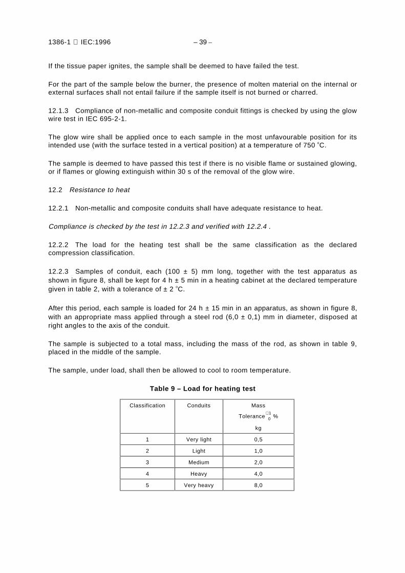
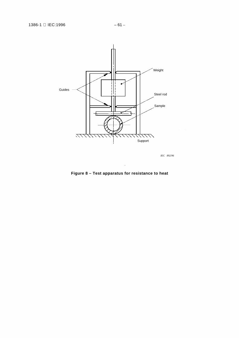
12.2.3 Samples of conduit, each (100 ± 5) mm long, together with the test apparatus asshown in figure 8, shall be kept for 4 h ± 5 min in a heating cabinet at the declared temperaturegiven in table 2, with a tolerance of ± 2 oC.
After this period, each sample is loaded for 24 h ± 15 min in an apparatus, as shown in figure 8,with an appropriate mass applied through a steel rod (6,0 ± 0,1) mm in diameter, disposed atright angles to the axis of the conduit.
The sample is subjected to a total mass, including the mass of the rod, as shown in table 9,placed in the middle of the sample.
The sample, under load, shall then be allowed to cool to room temperature.
Table 9 – Load for heating test
Classification Conduits Mass
Tolerance 01+ %
kg
1 Very light 0,5
2 Light 1,0
3 Medium 2,0
4 Heavy 4,0
5 Very heavy 8,0

1386-1 IEC:1996 – 41 –
12.2.4 The load is then removed, and immediately after its removal, it shall be possible topass the appropriate gauge, specified in the relevant part 2, through the conduit, under its ownweight and without any initial speed, with the sample in the vertical position.
13 Fire effects
Under consideration.
14 External influences
14.1 Degree of protection provided by enclosure
Conduit systems, when assembled in accordance with the manufacturer’s instructions, shallhave adequate resistance to external influences according to the classification declared by themanufacturer, with a minimum requirement of IP30.
Compliance is checked by the tests specified in 14.1.1 and 14.1.2.
14.1.1 Degree of protection – Ingress of foreign solid objects
14.1.1.1 An assembly is made of a conduit fitting with a short length of conduit assembled ineach entry. Where necessary, the open ends of the assembly are plugged, or are not part ofthe test.
14.1.1.2 The assembly shall be tested in accordance with the appropriate test of IEC 529. Fornumeral 5, category 2 applies.
14.1.1.3 The assembly, tested for numeral 5 or 6, shall be deemed to have passed the test ifthere is no ingress of dust visible to normal or corrected vision without magnification.
14.1.2 Degree of protection – Ingress of water
14.1.2.1 An assembly is made of a conduit fitting with a short length of conduit assembled ineach conduit entry. Where necessary, the open end of the conduit is plugged, or is not part ofthe test.
14.1.2.2 The assembly shall be tested in accordance with the appropriate test of IEC 529.
14.1.2.3 The assembly, tested for numeral 1 and above, shall be deemed to have passed thetest if there is not sufficient ingress of water to form a drop visible to normal or corrected visionwithout magnification.
14.2 Resistance against corrosion
14.2.1 Metallic and composite conduit systems, excluding screw threads, shall have adequateresistance against corrosion, both inside and outside, in accordance with the classificationgiven in table 10.
Compliance is checked by the tests specified in 14.2.2.1, 14.2.2.2 and 14.2.2.3.

1386-1 IEC:1996 – 43 –
14.2.2 Tests for resistance to corrosion for steel and steel composite conduit systems
14.2.2.1 Low protection conduit and conduit fittings shall be inspected for completeness ofcovering by the protective coating, both inside and outside.
14.2.2.2 Medium protection conduit and conduit fittings shall be cleaned with a piece ofwadding soaked in trichloroethane or similar agent and then dried.
They shall then be totally immersed in a solution of 0,75 % potassium ferricyanide [K3Fe(CN)6]and 0,25 % ammonium persulphate [(NH4)2S2O8] in water and a quantity of about 0,1 % of asuitable wetting agent, for instance a sodium salt of an alkylnaphthaline sulphonic acid, shall beadded.
The solution and the samples shall be maintained at a temperature of (23 ± 2) oC.
Each sample shall be tested separately, a fresh solution being used each time.
After immersion for 5 min 05+ s, the samples shall be removed from the solution and left to dry at
ambient temperature in air. After completion of the test as described above, the samples shallshow no more than two blue coloured spots on each square centimetre of the surface, and noblue spot shall have a dimension larger than 1,5 mm. Traces of rust on sharp edges, screwthreads and machined surfaces, also any yellowish film removable by rubbing, shall be ignored.
Table 10 – Resistance to corrosion classification
Classification Protection afforded Example
1 Low protection, inside and outside Priming paint
2 Medium protection, inside andoutside
Stove enamel/electro zincplate/air drying paint
3 Medium/High composite protectioninside: class 2
outside: class 4Stove enamelSherardizing
4 High protection, inside and outside Hot dip zinc coatingSherardizing
Stainless steel
14.2.2.3 High protection conduit and conduit fittings shall be degreased by immersion intrichloroethane or a similar degreasing agent for 10 min 0
5+ s, and wiped dry with a piece of soft
cloth. They shall then be immersed in a 2 % solution of sulphuric acid in water for 15 s,thoroughly cleaned in running water and again wiped dry with a piece of clean soft cloth. Eachsample shall then be totally immersed in a solution of copper sulphate (CuSO4 5H2O) indistilled water, having a specific gravity of 1,186 kg/l at (23 ± 2) oC.
The solution and the samples shall be maintained at a temperature of (23 ± 2) oC, withoutstirring.

1386-1 IEC:1996 – 45 –
NOTE – The solution is made by dissolving 360 g of crystalline copper sulphate in 1l of distilled water andneutralising with copper carbonate or copper hydroxide (about 1 g/l). The specific gravity is then checked andadjusted as necessary.
The container shall be such that it will not react with the solution and it shall be of such a sizeas to provide clearance of at least 25 mm between the walls thereof and the sample.
Each sample shall be immersed four times in succession in the same solution, each time for1 min 0
5+ s. A fresh solution shall be used for each sample. After each immersion, the sample
shall immediately be cleaned in running water with a brush to remove any black deposit. Thesample shall then be wiped dry with a piece of clean soft cloth, and, except after the fourthimmersion, returned to the solution. Care should be taken to clean out all holes and pockets.
After the test, the sample shall show no precipitation of copper which cannot be scrubbed off inrunning water, if necessary after immersion for 15 s in a 10 % solution of hydrochloric acid inwater.
Traces of copper precipitation on screw threads, sharp edges and machined surfaces may beignored.
14.2.3 Tests for resistance to corrosion for metals other than steel
Under consideration.
15 Electromagnetic compatibility
Products covered by this standard are, in normal use, passive in respect of electromagneticinfluences (emission and immunity).
NOTE – When products covered by this standard are installed as part of a wiring installation, the installationmay emit, or may be influenced by, electromagnetic signals. The degree of influence will depend on the natureof the installation within its operating environment and the apparatus connected by the wiring.

1386-1 IEC:1996 – 47 –
IEC 885/96
SampleSteel support
R = 1 R = 1
Force
≈ 50 50 ± 0,5
≈ 50
Force
Intermediate steel piece
Dimensions in millimetres
Figure 1 – Arrangement for compression test

1386-1 IEC:1996 – 49 –
Steel block
Fall height
Hammer
Steel intermediatepiece 100 g
Sample
∅ 10,5
∅ 20
AA
IEC 886/96
R = 300
40
Slightly roundededges
8,68,6
8,6
Dimensions in millimetres
Figure 2 – Impact test apparatus

1386-1 IEC:1996 – 51 –
Electrode* Electrode*
Securing strapSecuring strap
V
IEC 887/96
* Protective coating to be removed to providedirect metal connection for electrodes
Conduitfitting
Conduit
Board of insulatingmaterial
Dimensions in millimetres
Figure 3 – Assembly of conduit and conduit fitting for bonding test

1386-1 IEC:1996 – 53 –
Test voltage
100 mA trip or meter10 µA d.c.
IEC 888/96
Insulating seal
Conduit
Electrode Electrode
Figure 4 – Arrangement for insulation resistance and electric strength test – Rigid conduit

1386-1 IEC:1996 – 55 –
Test voltage
100 mA trip ormeter 10 µA d.c.
IEC 889/96
Conduit
ElectrodeElectrode
NOTE – Remove sharp edges and burrs.
Figure 5 – Arrangement for insulation resistance and electric strength test –Pliable and flexible conduit

1386-1 IEC:1996 – 57 –
Closed back surface
1300 ± 25
0300
0
IEC 890/96
450
Lowersurface
Material: metalDimensions in millimetresAll measurements given inside.
+25
+25
NOTE – This drawing is not intended to govern design except as regards the dimensions shown.
Figure 6 – Enclosure for burning test

1386-1 IEC:1996 – 59 –
Steel rod, diameter according to 12.1.2.1
Sample centrally located inthe horizontal plane
1225 min.100 ± 10
45° ± 2°
500 ± 10
550 ± 10
675 ± 10
100 ± 5
25
25
10 mm white pinewoodboard
Width:
Back face
Tissue paper
Flame
Pince
300-25
0
IEC 891/96
450-25
0
Dimensions in millimetres
NOTE – This drawing is not intended to govern design except as regards the dimensions shown.
Figure 7 – Arrangement for burning test
1386-1 IEC:1996 – 61 –
IEC 892/96
Steel rod
Sample
Weight
Support
Guides
Figure 8 – Test apparatus for resistance to heat

1386-1 IEC:1996 – 63 –
Annex A(normative)
Classification coding for conduit systems
NOTE – Annex A shows the classification coding format for declared properties of the conduit system, whichmay be incorporated in the manufacturer's literature.
First digit – Resistance to compression(see 6.1.1)
Very light compression strength 1
Light compression strength 2
Medium compression strength 3
Heavy compression strength 4
Very heavy compression strength 5
Second digit – Resistance to impact(see 6.1.2)
Very light impact strength 1
Light impact strength 2
Medium impact strength 3
Heavy impact strength 4
Very heavy impact strength 5
Third digit – Lower temperature range (see table 1)
+5 °C 1
-5 °C 2
-15 °C 3
-25°C 4
-45 °C 5
Fourth digit – Upper temperature range(see table 2)
+60 °C 1
+90 °C 2
+105 °C 3
+120 °C 4
+150 °C 5
+250 °C 6
+400 °C 7

1386-1 IEC:1996 – 65 –
Fifth digit – Resistance to bending(see 6.1.3)
Rigid 1
Pliable 2
Pliable / self recovering 3
Flexible 4
Sixth digit – Electrical characteristics(see 6.3)
None declared 0
With electrical continuity characteristics 1
With electrical insulating characteristics 2
With electrical continuity and insulatingcharacteristics
3
Seventh digit – Protection against ingress of solid objects(see 6.4.1)
Protected against solid foreign objectsof 2,5 mm diameter and greater
3
Protected against solid foreign objectsof 1,0 mm diameter and greater
4
Dust protected 5
Dust-tight 6
Eighth digit – Protection against ingress of water(see 6.4.2)
None declared 0
Protected against vertically falling water drops 1
Protected against vertically falling water dropswhen the conduit system is tilted up to anangle of 15°
2
Protected against spraying water 3
Protected against splashing water 4
Protected against water jets 5
Protected against powerful water jets 6
Protected against the effects of temporaryimmersion in water
7
Ninth digit – Resistance against corrosion(see 6.4.3 and table 10)
Low protection inside and outside 1
Medium protection inside and outside 2
Medium protection inside, high protectionoutside
3
High protection inside and outside 4

1386-1 IEC:1996 – 67 –
Tenth digit – Tensile strength(see 6.1.4)
None declared 0
Very light tensile strength 1
Light tensile strength 2
Medium tensile strength 3
Heavy tensile strength 4
Very heavy tensile strength 5
Eleventh digit – Resistance to flame propagation(see 6.5)
Non-flame propagating 1
Flame propagating 2
Twelfth digit – Suspended load capacity(see 6.1.5)
None declared 0
Very light suspended load capacity 1
Light suspended load capacity 2
Medium suspended load capacity 3
Heavy suspended load capacity 4
Very heavy suspended load capacity 5
Thirteenth digit – Fire effects
Under consideration.
__________


ICS 29.120.10
Typeset and printed by the IEC Central OfficeGENEVA, SWITZERLAND