international iec standard 62271-200parstasis.com/wp-content/uploads/2015/04/iec-62271-200.pdf ·...
TRANSCRIPT
High-voltage switchgear and controlgear –
Part 200: AC metal-enclosed switchgear and controlgear for rated voltages above 1 kV and up to and including 52 kV
Reference number IEC 62271-200:2003(E)
INTERNATIONAL STANDARD
IEC62271-200
First edition2003-11
This English-language version is derived from the original bilingual publication by leaving out all French-language pages. Missing page numbers correspond to the French-language pages.
Customer: hamid fakharian - No. of User(s): 1 - Company: nriOrder No.: WS-2007-005835 - IMPORTANT: This file is copyright of IEC, Geneva, Switzerland. All rights reserved.This file is subject to a licence agreement. Enquiries to Email: [email protected] - Tel.: +41 22 919 02 11
Publication numbering
As from 1 January 1997 all IEC publications are issued with a designation in the 60000 series. For example, IEC 34-1 is now referred to as IEC 60034-1.
Consolidated editions
The IEC is now publishing consolidated versions of its publications. For example, edition numbers 1.0, 1.1 and 1.2 refer, respectively, to the base publication, the base publication incorporating amendment 1 and the base publication incorporating amendments 1 and 2.
Further information on IEC publications
The technical content of IEC publications is kept under constant review by the IEC, thus ensuring that the content reflects current technology. Information relating to this publication, including its validity, is available in the IEC Catalogue of publications (see below) in addition to new editions, amendments and corrigenda. Information on the subjects under consideration and work in progress undertaken by the technical committee which has prepared this publication, as well as the list of publications issued, is also available from the following:
• IEC Web Site (www.iec.ch)
• Catalogue of IEC publications
The on-line catalogue on the IEC web site (www.iec.ch/searchpub) enables you to search by a variety of criteria including text searches, technical committees and date of publication. On-line information is also available on recently issued publications, withdrawn and replaced publications, as well as corrigenda.
• IEC Just Published
This summary of recently issued publications (www.iec.ch/online_news/ justpub) is also available by email. Please contact the Customer Service Centre (see below) for further information.
• Customer Service Centre
If you have any questions regarding this publication or need further assistance, please contact the Customer Service Centre:
Email: [email protected] Tel: +41 22 919 02 11 Fax: +41 22 919 03 00
Customer: hamid fakharian - No. of User(s): 1 - Company: nriOrder No.: WS-2007-005835 - IMPORTANT: This file is copyright of IEC, Geneva, Switzerland. All rights reserved.This file is subject to a licence agreement. Enquiries to Email: [email protected] - Tel.: +41 22 919 02 11
High-voltage switchgear and controlgear –
Part 200: AC metal-enclosed switchgear and controlgear for rated voltages above 1 kV and up to and including 52 kV
For price, see current catalogue
IEC 2003 Copyright - all rights reserved
No part of this publication may be reproduced or utilized in any form or by any means, electronic or mechanical, including photocopying and microfilm, without permission in writing from the publisher.
International Electrotechnical Commission, 3, rue de Varembé, PO Box 131, CH-1211 Geneva 20, SwitzerlandTelephone: +41 22 919 02 11 Telefax: +41 22 919 03 00 E-mail: [email protected] Web: www.iec.ch
INTERNATIONAL STANDARD
IEC62271-200
First edition2003-11
XC Commission Electrotechnique InternationaleInternational Electrotechnical CommissionМеждународная Электротехническая Комиссия
PRICE CODE
Customer: hamid fakharian - No. of User(s): 1 - Company: nriOrder No.: WS-2007-005835 - IMPORTANT: This file is copyright of IEC, Geneva, Switzerland. All rights reserved.This file is subject to a licence agreement. Enquiries to Email: [email protected] - Tel.: +41 22 919 02 11
62271-200 © IEC:2003 – 3 –
CONTENTS
FOREWORD .......................................................................................................................... 91 General...........................................................................................................................17
1.1 Scope ....................................................................................................................171.2 Normative references.............................................................................................19
2 Normal and special service conditions .............................................................................213 Terms and definitions......................................................................................................214 Ratings ...........................................................................................................................33
4.1 Rated voltage (Ur) ..................................................................................................334.2 Rated insulation level .............................................................................................334.3 Rated frequency (fr) ...............................................................................................334.4 Rated normal current and temperature rise ............................................................334.5 Rated short-time withstand current (Ik) ...................................................................354.6 Rated peak withstand current (Ip) ...........................................................................354.7 Rated duration of short circuit (tk)...........................................................................354.8 Rated supply voltage of closing and opening devices and of auxiliary and
control circuits (Ua) ................................................................................................354.9 Rated supply frequency of closing and opening devices and of auxiliary
circuits ...................................................................................................................354.10 Rated pressure of compressed gas supply for insulation and/or operation...............35
4.10.1 Rated filling level (of fluid-filled compartments)...........................................355 Design and construction ..................................................................................................37
5.1 Requirements for liquids in switchgear and controlgear ..........................................375.2 Requirements for gases in switchgear and controlgear ...........................................375.3 Earthing .................................................................................................................375.4 Auxiliary and control equipment..............................................................................415.5 Dependent power operation ...................................................................................415.6 Stored energy operation .........................................................................................415.7 Independent manual operation ...............................................................................415.8 Operation of releases.............................................................................................415.9 Low- and high-pressure interlocking and monitoring devices...................................415.10 Nameplates ...........................................................................................................415.11 Interlocking devices ...............................................................................................435.12 Position indication ..................................................................................................455.13 Degrees of protection by enclosures.......................................................................455.14 Creepage distances ...............................................................................................455.15 Gas and vacuum tightness .....................................................................................455.16 Liquid tightness......................................................................................................475.17 Flammability ..........................................................................................................475.18 Electromagnetic compatibility (EMC) ......................................................................47
6 Type tests .......................................................................................................................596.1 General .................................................................................................................596.2 Dielectric tests .......................................................................................................636.3 Radio interference voltage (r.i.v.) test .....................................................................696.4 Measurement of the resistance of circuits...............................................................716.5 Temperature-rise tests ...........................................................................................716.6 Short-time withstand current and peak withstand current tests ................................73
Customer: hamid fakharian - No. of User(s): 1 - Company: nriOrder No.: WS-2007-005835 - IMPORTANT: This file is copyright of IEC, Geneva, Switzerland. All rights reserved.This file is subject to a licence agreement. Enquiries to Email: [email protected] - Tel.: +41 22 919 02 11
62271-200 © IEC:2003 – 5 –
6.7 Verification of the protection...................................................................................776.8 Tightness tests ......................................................................................................776.9 Electromagnetic compatibility tests (EMC) ..............................................................776.10 Additional tests on auxiliary and control circuits ......................................................77
7 Routine tests...................................................................................................................857.1 Dielectric test on the main circuit............................................................................877.2 Tests on auxiliary and control circuits .....................................................................877.3 Measurement of the resistance of the main circuit ..................................................877.4 Tightness test ........................................................................................................877.5 Design and visual checks .......................................................................................87
8 Guide to the selection of metal-enclosed switchgear and controlgear for service ..............918.1 Selection of rated values ........................................................................................918.2 Selection of design and construction ......................................................................918.3 Internal arc classification........................................................................................97
9 Information to be given with enquiries, tenders and orders.............................................10510 Rules for transport, storage, installation, operation and maintenance .............................109
10.1 Conditions during transport, storage and installation.............................................10910.2 Installation ...........................................................................................................10910.3 Operation.............................................................................................................10910.4 Maintenance ........................................................................................................109
11 Safety ...........................................................................................................................111
Annex A (normative) Internal fault − Method for testing the metal-enclosed switchgearand controlgear under conditions of arcing due to an internal fault .......................................113A.1 Introduction...................................................................................................................113A.2 Types of accessibility ....................................................................................................115A.3 Test arrangements ........................................................................................................115A.4 Current and voltage applied...........................................................................................123A.5 Test procedure..............................................................................................................125A.6 Acceptance criteria .......................................................................................................127A.7 Test report ....................................................................................................................129A.8 Designation of IAC classification....................................................................................131
Annex B (normative) Partial discharge measurement ..........................................................145B.1 General.........................................................................................................................145B.2 Application ....................................................................................................................145B.3 Test circuits and measuring instruments........................................................................147B.4 Test procedure..............................................................................................................147B.5 Maximum permissible partial discharge quantity ............................................................149
Annex C (informative) Explanatory notes ............................................................................157C.1 Changes in classifications, compared to the third edition (1990) of IEC 60298 ...............157C.2 ANSI defined metal-clad................................................................................................163
Customer: hamid fakharian - No. of User(s): 1 - Company: nriOrder No.: WS-2007-005835 - IMPORTANT: This file is copyright of IEC, Geneva, Switzerland. All rights reserved.This file is subject to a licence agreement. Enquiries to Email: [email protected] - Tel.: +41 22 919 02 11
62271-200 © IEC:2003 – 7 –
C.3 Former IEC defined metal-clad in terms of IEC 62271-200 definitions ............................163C.4 Example of modular fuse-switch type.............................................................................165
Bibliography ........................................................................................................................169
Figure A.1 – Mounting frame for vertical indicators...............................................................133Figure A.2 – Horizontal indicator ..........................................................................................133Figure A.3 – Position of the indicators..................................................................................135Figure A.4 – Room simulation and indicator positioning for accessibility A, functionalunit at or above 1,5 m..........................................................................................................137Figure A.5 – Room simulation and indicator positioning for accessibility B, functionalunit above 2 m high .............................................................................................................139Figure A.6 – Room simulation and indicator positioning for accessibility B, functionalunit below 2 m high .............................................................................................................141Figure A.7 – Test arrangement for overhead connected pole-mounted switchgear andcontrolgear ..........................................................................................................................143Figure B.1 – Partial discharge test circuit (three-phase arrangement) ...................................153Figure B.2 – Partial-discharge test circuit (system without earthed neutral)...........................155
Table 1 – Nameplate information ...........................................................................................41Table 2– Locations, causes and examples of measures to decrease the probability ofinternal faults ........................................................................................................................99Table 3 – Summary of technical requirements, ratings and optional tests for metalenclosed switchgear ............................................................................................................101Table B.1 – Test circuits and procedures .............................................................................151Table C.1 – Comparison of IEC and IEEE definition of metal-clad .......................................157Table C.2 – Classification related to personnel safety in case of internal arc ........................159
Customer: hamid fakharian - No. of User(s): 1 - Company: nriOrder No.: WS-2007-005835 - IMPORTANT: This file is copyright of IEC, Geneva, Switzerland. All rights reserved.This file is subject to a licence agreement. Enquiries to Email: [email protected] - Tel.: +41 22 919 02 11
62271-200 © IEC:2003 – 9 –
INTERNATIONAL ELECTROTECHNICAL COMMISSION____________
HIGH-VOLTAGE SWITCHGEAR AND CONTROLGEAR –
Part 200: AC metal-enclosed switchgear and controlgearfor rated voltages above 1 kV and up to and including 52 kV
FOREWORD1) The International Electrotechnical Commission (IEC) is a worldwide organization for standardization comprising
all national electrotechnical committees (IEC National Committees). The object of IEC is to promoteinternational co-operation on all questions concerning standardization in the electrical and electronic fields. Tothis end and in addition to other activities, IEC publishes International Standards, Technical Specifications,Technical Reports, Publicly Available Specifications (PAS) and Guides (hereafter referred to as “IECPublication(s)”). Their preparation is entrusted to technical committees; any IEC National Committee interestedin the subject dealt with may participate in this preparatory work. International, governmental and non-governmental organizations liaising with the IEC also participate in this preparation. IEC collaborates closelywith the International Organization for Standardization (ISO) in accordance with conditions determined byagreement between the two organizations.
2) The formal decisions or agreements of IEC on technical matters express, as nearly as possible, an internationalconsensus of opinion on the relevant subjects since each technical committee has representation from allinterested IEC National Committees.
3) IEC Publications have the form of recommendations for international use and are accepted by IEC NationalCommittees in that sense. While all reasonable efforts are made to ensure that the technical content of IECPublications is accurate, IEC cannot be held responsible for the way in which they are used or for anymisinterpretation by any end user.
4) In order to promote international uniformity, IEC National Committees undertake to apply IEC Publicationstransparently to the maximum extent possible in their national and regional publications. Any divergencebetween any IEC Publication and the corresponding national or regional publication shall be clearly indicated inthe latter.
5) IEC provides no marking procedure to indicate its approval and cannot be rendered responsible for anyequipment declared to be in conformity with an IEC Publication.
6) All users should ensure that they have the latest edition of this publication.
7) No liability shall attach to IEC or its directors, employees, servants or agents including individual experts andmembers of its technical committees and IEC National Committees for any personal injury, property damage orother damage of any nature whatsoever, whether direct or indirect, or for costs (including legal fees) andexpenses arising out of the publication, use of, or reliance upon, this IEC Publication or any other IECPublications.
8) Attention is drawn to the Normative references cited in this publication. Use of the referenced publications isindispensable for the correct application of this publication.
9) Attention is drawn to the possibility that some of the elements of this IEC Publication may be the subject ofpatent rights. IEC shall not be held responsible for identifying any or all such patent rights.
International Standard IEC 62271-200 has been prepared by subcommittee 17C: High-voltageswitchgear and controlgear assemblies, of IEC technical committee 17: Switchgear andcontrolgear.
This first edition of IEC 62271-200 cancels and replaces the third edition of IEC 60298,published in 1990, and constitutes a technical revision.
Significant technical changes from the third edition of IEC 60298 are as follows:
This revised document has been basically changed to be updated to today’s use of high-voltage switchgear and controlgear up to 52 kV. The main changes are: new definitions andclassification of equipment, introduction of internal arc classes (IAC) and its testing.
Customer: hamid fakharian - No. of User(s): 1 - Company: nriOrder No.: WS-2007-005835 - IMPORTANT: This file is copyright of IEC, Geneva, Switzerland. All rights reserved.This file is subject to a licence agreement. Enquiries to Email: [email protected] - Tel.: +41 22 919 02 11
62271-200 © IEC:2003 – 11 –
This standard is to be read in conjunction with IEC 606941 published in 1996. Clausenumbering follows the clause numbering of that standard. Additional subclauses, as they relateto a particular clause or subclause from IEC 60694, are numbered 101, 102, etc.
The text of this standard is based on the following documents:
FDIS Report on voting
17C/311/FDIS 17C/315/RVD
Full information on the voting for the approval of this standard can be found in the report onvoting indicated in the above table.
This publication has been drafted in accordance with the ISO/IEC Directives, Part 2.
The committee has decided that the contents of this publication will remain unchanged until2009. At this date, the publication will be
• reconfirmed;• withdrawn;• replaced by a revised edition, or• amended.
___________1 IEC 60694 (1996) will be replaced by IEC 62271-1 as soon as available.
Customer: hamid fakharian - No. of User(s): 1 - Company: nriOrder No.: WS-2007-005835 - IMPORTANT: This file is copyright of IEC, Geneva, Switzerland. All rights reserved.This file is subject to a licence agreement. Enquiries to Email: [email protected] - Tel.: +41 22 919 02 11
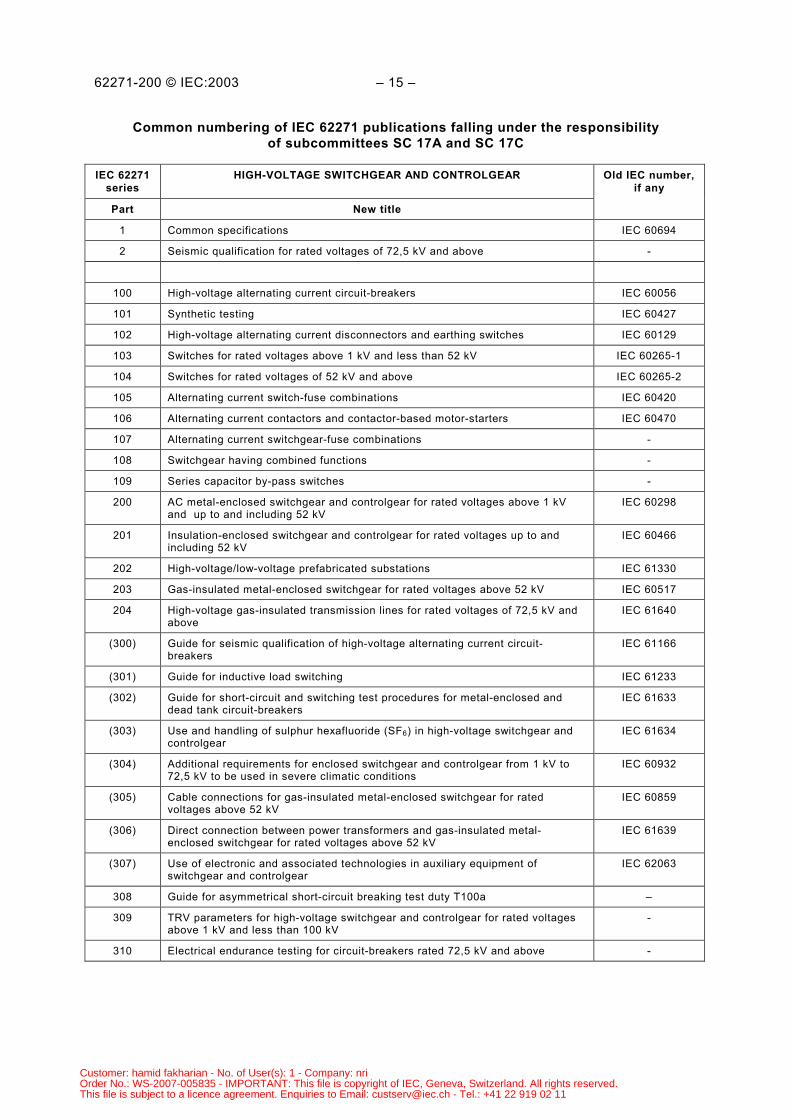
62271-200 © IEC:2003 – 13 –
COMMON NUMBERING OF IEC 62271 PUBLICATIONS FALLING UNDERTHE RESPONSIBILITY OF SUBCOMMITTEES SC 17A AND SC 17C
In accordance with the decision taken at the joint SC 17A/SC 17C meeting in Frankfurt, June1998 (item 20.7 of 17A/535/RM), a common numbering system has been established for thepublications falling under the responsibility of SC 17A and SC 17C. IEC 62271 – High-voltageswitchgear and controlgear is the publication number and main title element for the commonpublications.
The numbering of these publications will apply the following principle.
a) Common standards prepared by SC 17A and SC 17C will start with IEC 62271-1.b) Standards of SC 17A will start with IEC 62271-100.c) Standards of SC 17C will start with number IEC 62271-200.d) Publications prepared by SC 17A and SC 17C will start with number IEC 62271-300.
The table below relates the new numbers to the old numbers. The parts numbered (xxx) will begiven a final number pending the decision to publish the revised publication as standard ortechnical report.
Customer: hamid fakharian - No. of User(s): 1 - Company: nriOrder No.: WS-2007-005835 - IMPORTANT: This file is copyright of IEC, Geneva, Switzerland. All rights reserved.This file is subject to a licence agreement. Enquiries to Email: [email protected] - Tel.: +41 22 919 02 11
62271-200 © IEC:2003 – 15 –
Common numbering of IEC 62271 publications falling under the responsibilityof subcommittees SC 17A and SC 17C
IEC 62271series
HIGH-VOLTAGE SWITCHGEAR AND CONTROLGEAR
Part New title
Old IEC number,if any
1 Common specifications IEC 60694
2 Seismic qualification for rated voltages of 72,5 kV and above -
100 High-voltage alternating current circuit-breakers IEC 60056
101 Synthetic testing IEC 60427
102 High-voltage alternating current disconnectors and earthing switches IEC 60129
103 Switches for rated voltages above 1 kV and less than 52 kV IEC 60265-1
104 Switches for rated voltages of 52 kV and above IEC 60265-2
105 Alternating current switch-fuse combinations IEC 60420
106 Alternating current contactors and contactor-based motor-starters IEC 60470
107 Alternating current switchgear-fuse combinations -
108 Switchgear having combined functions -
109 Series capacitor by-pass switches -
200 AC metal-enclosed switchgear and controlgear for rated voltages above 1 kVand up to and including 52 kV
IEC 60298
201 Insulation-enclosed switchgear and controlgear for rated voltages up to andincluding 52 kV
IEC 60466
202 High-voltage/low-voltage prefabricated substations IEC 61330
203 Gas-insulated metal-enclosed switchgear for rated voltages above 52 kV IEC 60517
204 High-voltage gas-insulated transmission lines for rated voltages of 72,5 kV andabove
IEC 61640
(300) Guide for seismic qualification of high-voltage alternating current circuit-breakers
IEC 61166
(301) Guide for inductive load switching IEC 61233
(302) Guide for short-circuit and switching test procedures for metal-enclosed anddead tank circuit-breakers
IEC 61633
(303) Use and handling of sulphur hexafluoride (SF6) in high-voltage switchgear andcontrolgear
IEC 61634
(304) Additional requirements for enclosed switchgear and controlgear from 1 kV to72,5 kV to be used in severe climatic conditions
IEC 60932
(305) Cable connections for gas-insulated metal-enclosed switchgear for ratedvoltages above 52 kV
IEC 60859
(306) Direct connection between power transformers and gas-insulated metal-enclosed switchgear for rated voltages above 52 kV
IEC 61639
(307) Use of electronic and associated technologies in auxiliary equipment ofswitchgear and controlgear
IEC 62063
308 Guide for asymmetrical short-circuit breaking test duty T100a –
309 TRV parameters for high-voltage switchgear and controlgear for rated voltagesabove 1 kV and less than 100 kV
-
310 Electrical endurance testing for circuit-breakers rated 72,5 kV and above -
Customer: hamid fakharian - No. of User(s): 1 - Company: nriOrder No.: WS-2007-005835 - IMPORTANT: This file is copyright of IEC, Geneva, Switzerland. All rights reserved.This file is subject to a licence agreement. Enquiries to Email: [email protected] - Tel.: +41 22 919 02 11
62271-200 © IEC:2003 – 17 –
HIGH-VOLTAGE SWITCHGEAR AND CONTROLGEAR –
Part 200: AC metal-enclosed switchgear and controlgearfor rated voltages above 1 kV and up to and including 52 kV
1 General
1.1 Scope
This part of IEC 62271 specifies requirements for factory-assembled metal-enclosedswitchgear and controlgear for alternating current of rated voltages above 1 kV and up to andincluding 52 kV for indoor and outdoor installation, and for service frequencies up to andincluding 60 Hz. Enclosures may include fixed and removable components and may be filledwith fluid (liquid or gas) to provide insulation.
NOTE 1 Although primarily dedicated to three-phase systems, this standard can also be applied to single-phase ortwo-phase systems.
This standard defines several types of metal enclosed switchgear and controlgear which differdue to
– the consequences on network service continuity in case of maintenance on the switchgearand controlgear;
– the need and convenience of maintenance of the equipment.NOTE 2 Safety of an installation results from the design, implementation and coordination of products,installations and operations.
For metal-enclosed switchgear and controlgear containing gas-filled compartments, the designpressure is limited to a maximum of 300 kPa (relative pressure).
NOTE 3 Gas-filled compartments having a design pressure exceeding 300 kPa (relative pressure) should bedesigned and tested in accordance with IEC 60517.
Metal-enclosed switchgear and controlgear for special use, for example, in flammableatmospheres, in mines or on board ships, may be subject to additional requirements.
Components contained in metal-enclosed switchgear and controlgear are to be designed andtested in accordance with their various relevant standards. This standard supplements thestandards for the individual components regarding their installation in switchgear andcontrolgear assemblies.
This standard does not preclude that other equipment may be included in the same enclosure.In such a case, any possible influence of that equipment on the switchgear and controlgear isto be taken into account.
NOTE 4 Switchgear and controlgear assemblies having an insulation enclosure are covered by IEC 60466.
NOTE 5 Metal-enclosed switchgear and controlgear for rated voltages above 52 kV insulated by ambient air maybe covered by this standard taking into account the insulation levels of IEC 60694.
Customer: hamid fakharian - No. of User(s): 1 - Company: nriOrder No.: WS-2007-005835 - IMPORTANT: This file is copyright of IEC, Geneva, Switzerland. All rights reserved.This file is subject to a licence agreement. Enquiries to Email: [email protected] - Tel.: +41 22 919 02 11
62271-200 © IEC:2003 – 19 –
1.2 Normative references
The following referenced documents are indispensable for the application of this document. Fordated references, only the edition cited applies. For undated references, the latest edition ofthe referenced document (including any amendments) applies.
IEC 60050(151):2001, International Electrotechnical Vocabulary – Chapter 151: Electrical andmagnetic devices
IEC 60050(441):1984, International Electrotechnical Vocabulary – Chapter 441: Switchgear,controlgear and fuses
IEC 60060-1:1989, High-voltage test techniques – Part 1: General definitions and testrequirements
IEC 60243-1:1998, Electrical strength of insulating materials – Test methods – Part 1: Tests atpower frequencies
IEC 60265-1:1998, High-voltage switches – Part 1: Switches for rated voltages above 1 kV andless than 52 kV
IEC 60270:2000, High-voltage test techniques – Partial discharge measurements
IEC 60466:1987, AC insulation-enclosed switchgear and controlgear for rated voltages above 1kV and up to and including 38 kV
IEC 60470:2000, High-voltage alternating current contactors and contactor-based motor-starters
IEC 60480:1974, Guide to the checking of sulphur hexafluoride (SF6) taken from electricalequipment
IEC 60529:1989, Degrees of protection provided by enclosures (IP Code)
IEC 60694:1996, Common specifications for high-voltage switchgear and controlgear standards
IEC 60909-0:2001, Short-circuit currents in three-phase a.c. systems – Part 0: Calculation ofcurrents
IEC 60932:1988, Additional requirements for enclosed switchgear and controlgear from 1 kV to72,5 kV to be used in severe climatic conditions
IEC 61634:1995, High-voltage switchgear and controlgear – Use and handling of sulphurhexafluoride (SF6) in high-voltage switchgear and controlgear
IEC 62271-100:2001, High-voltage alternating-current circuit-breakers
IEC 62271-102:2001, High-voltage switchgear and controlgear – Part 102: Alternating currentdisconnectors and earthing switches
IEC 62271-105:2002, High-voltage switchgear and controlgear – Part 105: Alternating currentswitch-fuse combinations
ISO/IEC Guide 51:1999, Safety aspects – Guidelines for their inclusion in standards
Customer: hamid fakharian - No. of User(s): 1 - Company: nriOrder No.: WS-2007-005835 - IMPORTANT: This file is copyright of IEC, Geneva, Switzerland. All rights reserved.This file is subject to a licence agreement. Enquiries to Email: [email protected] - Tel.: +41 22 919 02 11
62271-200 © IEC:2003 – 21 –
2 Normal and special service conditions
Clause 2 of IEC 60694 is applicable with the following addition:
Unless otherwise specified in this standard, the metal-enclosed switchgear and controlgear isdesigned to be used under normal service conditions.
3 Terms and definitions
For the purposes of this document, the following definitions as well as the definitions ofIEC 60050(441), IEC 60050(151) and IEC 60694 apply, except where indicated. Some standarddefinitions are recalled here for ease of reference.
Additional definitions are classified so as to be aligned with the classification system used in IEC60050(441).
3.101switchgear and controlgeargeneral term covering switching devices and their combination with associated control,measuring, protective and regulating equipment, also assemblies of such devices andequipment with associated interconnections, accessories, enclosures and supporting structures
[IEV 441-11-01]
3.102metal-enclosed switchgear and controlgearswitchgear and controlgear assemblies with an external metal enclosure intended to be earthedand completely assembled, except for external connections
[IEV 441-12-04, modified]
3.103functional unit (of an assembly)part of metal-enclosed switchgear and controlgear comprising all the components of themain circuits and auxiliary circuits that contribute to the fulfilment of a single function
[IEV 441-13-04, modified]
NOTE Functional units may be distinguished according to the function for which they are intended, for example,incoming unit, outgoing unit, etc.
3.104multi-tiertwo or more functional units arranged vertically within a single enclosure
3.105transport unitpart of metal-enclosed switchgear and controlgear suitable for shipment without beingdismantled
3.106enclosurepart of metal-enclosed switchgear and controlgear providing a specified degree of protection ofequipment against external influences and a specified degree of protection against approach toor contact with live parts and against contact with moving parts
[IEV 441-13-01 modified]
Customer: hamid fakharian - No. of User(s): 1 - Company: nriOrder No.: WS-2007-005835 - IMPORTANT: This file is copyright of IEC, Geneva, Switzerland. All rights reserved.This file is subject to a licence agreement. Enquiries to Email: [email protected] - Tel.: +41 22 919 02 11
62271-200 © IEC:2003 – 23 –
3.107compartmentpart of metal-enclosed switchgear and controlgear enclosed except for openings necessary forinterconnection, control or ventilation
[IEV 441-13-05, modified]
Four types of compartments are distinguished, three that can be opened, called accessible(see 3.107.1 to 3.107.3) and one that cannot be opened, called non-accessible (see 3.107.4)
NOTE Compartments are identified according to the main component(s) contained therein (refer to 5.103.1).
3.107.1interlock-controlled accessible compartmentcompartment containing high-voltage parts, intended to be opened for normal operation and/ornormal maintenance as stated by the manufacturer, in which access is controlled by integraldesign of the switchgear and controlgear
NOTE Installation, extension, repairing, etc. are not considered as normal maintenance.
3.107.2procedure-based accessible compartmentcompartment containing high-voltage parts, intended to be opened for normal operation and/ornormal maintenance as stated by the manufacturer, in which access is controlled by a suitableprocedure combined with locking
NOTE Installation, extension, repairing, etc. are not considered as normal maintenance.
3.107.3tool-based accessible compartmentcompartment containing high-voltage parts, that may be opened, but not for normal operationand maintenance. Special procedures are required. Tools are necessary for opening
3.107.4non-accessible compartmentcompartment containing high-voltage parts that must not be opened. Opening may destroy theintegrity of the compartment. Clear indication not to open is provided on/by the compartment
3.108partitionpart of metal-enclosed switchgear and controlgear separating one compartment from othercompartments
[IEV 441-13-06, modified]
3.109partition classclass defining whether metallic or non-metallic material for separation to live parts is used
3.109.1partition class PMmetal-enclosed switchgear and controlgear providing continuous metallic partitions and/orshutters (if applicable), intended to be earthed, between opened accessible compartments andlive parts of the main circuit
Customer: hamid fakharian - No. of User(s): 1 - Company: nriOrder No.: WS-2007-005835 - IMPORTANT: This file is copyright of IEC, Geneva, Switzerland. All rights reserved.This file is subject to a licence agreement. Enquiries to Email: [email protected] - Tel.: +41 22 919 02 11
62271-200 © IEC:2003 – 25 –
3.109.2partition class PImetal-enclosed switchgear and controlgear having one or more non-metallic partitions orshutters between opened accessible compartments and live parts of the main circuit
3.110shutterpart of metal-enclosed switchgear and controlgear that can be moved from a position where itpermits contacts of a removable part, or moving contact of a disconnector, to engage fixedcontacts, to a position where it becomes a part of the enclosure or partition shielding the fixedcontacts
[IEV 441-13-07, modified]
3.111segregation (of conductors)arrangement of conductors with earthed metal interposed between them in such a manner thatdisruptive discharges can only occur to earth
[IEV 441-11-11]
NOTE A segregation may be established between the conductors as well as between the open contacts of aswitching device or disconnector.
3.112bushingstructure carrying one or more conductors through an enclosure or partition and insulating ittherefrom, including the means of attachment
3.113componentessential part of the main or earthing circuits of metal-enclosed switchgear and controlgearwhich serves a specific function (for example, circuit-breaker, disconnector, switch, fuse,instrument transformer, bushing, busbar)
3.114main circuit (of an assembly)all the conductive parts of metal-enclosed switchgear and controlgear included in a circuitwhich is intended to transmit electrical energy
[IEV 441-13-02, modified]
3.115earthing circuitconnection of each earthing device, or points provided for earthing purposes, to the terminalintended to be connected to the earthing system of the installation
3.116auxiliary circuitall the conductive parts of metal-enclosed switchgear and controlgear included in a circuit(other than the main circuit) intended to control, measure, signal and regulate
[IEV 441-13-03, modified]
NOTE The auxiliary circuits of metal-enclosed switchgear and controlgear include the control and auxiliary circuitsof the switching devices.
Customer: hamid fakharian - No. of User(s): 1 - Company: nriOrder No.: WS-2007-005835 - IMPORTANT: This file is copyright of IEC, Geneva, Switzerland. All rights reserved.This file is subject to a licence agreement. Enquiries to Email: [email protected] - Tel.: +41 22 919 02 11
62271-200 © IEC:2003 – 27 –
3.117pressure relief devicedevice intended to limit the pressure in a fluid-filled compartment
3.118fluid-filled compartmentcompartment of metal-enclosed switchgear and controlgear filled with a fluid, either gas, otherthan ambient air, or liquid, for insulation purposes
3.118.1gas-filled compartmentrefer to 3.6.5.1 of IEC 60694
3.118.2liquid-filled compartmentcompartment of metal-enclosed switchgear and controlgear in which the liquid is atatmospheric pressure, or under pressure that is maintained by one of the following systems:
a) controlled pressure system;b) closed pressure system;c) sealed pressure system.
For pressure systems, refer to 3.6.4 of IEC 60694
3.119relative pressurepressure, referred to the standard atmospheric pressure of 101,3 kPa
3.120minimum functional level (of fluid-filled compartments)gas pressure (relative pressure) in Pa (or density) or liquid mass at and above which the ratedvalues of the metal-enclosed switchgear and controlgear are maintained
3.121design level (of fluid-filled compartments)gas pressure (relative pressure) in Pa (or density) or liquid mass used to determine the designof a gas-filled compartment or mass for a liquid-filled compartment
3.122design temperature (of fluid-filled compartments)highest temperature which can be reached by the gas or liquid under service conditions
3.123ambient air temperature (of metal-enclosed switchgear and controlgear)temperature, determined under prescribed conditions, of the air surrounding the enclosure ofmetal-enclosed switchgear and controlgear
3.124removable partpart of metal-enclosed switchgear and controlgear connected to the main circuit and that maybe removed entirely from the metal-enclosed switchgear and controlgear and replaced, eventhough the main circuit of the functional unit is live
[IEV 441-13-08, modified]
Customer: hamid fakharian - No. of User(s): 1 - Company: nriOrder No.: WS-2007-005835 - IMPORTANT: This file is copyright of IEC, Geneva, Switzerland. All rights reserved.This file is subject to a licence agreement. Enquiries to Email: [email protected] - Tel.: +41 22 919 02 11
62271-200 © IEC:2003 – 29 –
3.125withdrawable partremovable part of metal-enclosed switchgear and controlgear that can be moved to positions inwhich an isolating distance or segregation between open contacts is established, while the partremains mechanically attached to the enclosure
[IEV 441-13-09, modified]
3.126service position (connected position)position of a removable part in which it is fully connected for its intended function
[IEV 441-16-25]
3.127earthing positionposition of a removable part or state of a disconnector in which the closing of a mechanicalswitching device causes a main circuit to be short-circuited and earthed
[IEV 441-16-26, modified]
3.128test position (of a withdrawable part)position of a withdrawable part in which an isolating distance or segregation is established inthe main circuit and in which the auxiliary circuits are connected
[IEV 441-16-27]
3.129disconnected position (of a withdrawable part)position of a withdrawable part in which an isolating distance or segregation is established inthe circuits of the withdrawable part, that part remaining mechanically attached to theenclosure
[IEV 441-16-28, modified]
NOTE In high-voltage metal-enclosed switchgear and controlgear, the auxiliary circuits may not be disconnected.
3.130removed position (of a removable part)position of a removable part when it is outside and mechanically and electrically separatedfrom the enclosure
[IEV 441-16-29, modified]
3.131loss of service continuity category (LSC)category defining the possibility to keep other compartments and/or functional units energisedwhen opening a main circuit compartment
NOTE 1 The LSC category describes the extent to which the switchgear and controlgear are intended to remainoperational in case access to a main-circuit compartment is necessary. The extent to which it is considerednecessary to open main-circuit compartments with a live installation might be dependent on several aspects (referto 8.2).
NOTE 2 The LSC category does not describe ranks of reliability of switchgear and controlgear (refer to 8.2).
Customer: hamid fakharian - No. of User(s): 1 - Company: nriOrder No.: WS-2007-005835 - IMPORTANT: This file is copyright of IEC, Geneva, Switzerland. All rights reserved.This file is subject to a licence agreement. Enquiries to Email: [email protected] - Tel.: +41 22 919 02 11
62271-200 © IEC:2003 – 31 –
3.131.1category LSC2 switchgear and controlgearswitchgear and controlgear having accessible compartments other than the busbar compart-ment of a single busbar switchgear and controlgearFor metal-enclosed switchgear and controlgear, when any accessible compartment in afunctional unit is open, all other functional units are intended to remain energized and operatednormally. An exception applies in the case of the busbar compartment of single-busbarswitchgear and controlgear which, when opened, prevents service continuity.Two subdivisions are recognized:LSC2B: switchgear and controlgear of category LSC2 where the cable compartment is alsointended to remain energized when any other accessible compartment of the correspondingfunctional unit is open.LSC2A: LSC2 switchgear and controlgear, other than LSC2B
3.131.2category LSC1 switchgear and controlgearmetal-enclosed switchgear and controlgear other than category LSC2
3.132internal arc classified switchgear and controlgear (IAC)metal-enclosed switchgear and controlgear for which prescribed criteria for protection ofpersons are met in the event of internal arc as demonstrated by the appropriate tests
NOTE Refer to Annex A for additional information.
3.133degree of protectionextent of protection provided by an enclosure, partition or shutter if applicable, against accessto hazardous parts, against ingress of solid foreign objects and/or ingress of water and verifiedby standardized test methods
(see 3.3 of IEC 60529)
3.134rated valuequantity value assigned, generally by a manufacturer, for a specified operating condition of acomponent device or equipment
[IEV 151-16-08, modified]
NOTE Refer to Clause 4 for individual rated values.
3.135disruptive dischargephenomena associated with the failure of insulation under electric stress, in which thedischarge completely bridges the insulation under test, reducing the voltage between theelectrodes to zero or nearly to zero
NOTE 1 The term applies to discharges in solid, liquid and gaseous dielectrics and to combinations of these.
NOTE 2 A disruptive discharge in a solid dielectric produces permanent loss of dielectric strength (non-self-restoring insulation); in a liquid or gaseous dielectric, the loss may be only temporary (self-restoring insulation).
NOTE 3 The term "sparkover" is used when a disruptive discharge occurs in a gaseous or liquid dielectric. Theterm "flashover" is used when a disruptive discharge occurs over the surface of a solid dielectric in gaseous orliquid medium. The term "puncture" is used when a disruptive discharge occurs through a solid dielectric.
Customer: hamid fakharian - No. of User(s): 1 - Company: nriOrder No.: WS-2007-005835 - IMPORTANT: This file is copyright of IEC, Geneva, Switzerland. All rights reserved.This file is subject to a licence agreement. Enquiries to Email: [email protected] - Tel.: +41 22 919 02 11
62271-200 © IEC:2003 – 33 –
4 Ratings
The ratings of metal-enclosed switchgear and controlgear are the following:
a) rated voltage (Ur) and number of phases;b) rated insulation level;c) rated frequency (fr);d) rated normal current (Ir) (for main circuits);e) rated short-time withstand current (Ik) (for main and earthing circuits);f) rated peak withstand current (Ip), if applicable (for main and earthing circuits);g) rated duration of short circuit (tk) (for main and earthing circuits);h) rated values of the components forming part of the metal-enclosed switchgear and
controlgear including their operating devices and auxiliary equipment;i) rated filling level (of fluid-filled compartments).
4.1 Rated voltage (Ur)
Subclauses 4.1 and 4.1.1 of IEC 60694 are applicable.
NOTE Components forming part of metal-enclosed switchgear and controlgear may have individual values of ratedvoltage in accordance with their relevant standards.
4.2 Rated insulation level
Subclause 4.2 of IEC 60694 is applicable.
4.3 Rated frequency (fr)
Subclause 4.3 of IEC 60694 is applicable.
4.4 Rated normal current and temperature rise
4.4.1 Rated normal current (Ir)
Subclause 4.4.1 of IEC 60694 is applicable with the following addition:
Some main circuits of metal-enclosed switchgear and controlgear (for example, busbars,feeder circuits, etc.) may have differing values of rated normal current.
4.4.2 Temperature rise
Subclause 4.4.2 of IEC 60694 is applicable with the following addition:
The temperature rise of components contained in metal-enclosed switchgear and controlgearwhich are subject to individual specifications not covered by the scope of IEC 60694 shall notexceed the temperature-rise limits permitted in the relevant standard for that component.
The maximum permissible temperatures and temperature rises to be taken into account forbusbars are those specified for contacts, connections and metal parts in contact withinsulation, as the case may be.
Customer: hamid fakharian - No. of User(s): 1 - Company: nriOrder No.: WS-2007-005835 - IMPORTANT: This file is copyright of IEC, Geneva, Switzerland. All rights reserved.This file is subject to a licence agreement. Enquiries to Email: [email protected] - Tel.: +41 22 919 02 11
62271-200 © IEC:2003 – 35 –
The temperature rise for accessible enclosures and covers shall not exceed 30 K. In the caseof enclosures and covers that are accessible but need not be touched during normal operation,the temperature-rise limit may be increased by 10 K, if not accessible to the public.
4.5 Rated short-time withstand current (Ik)
Subclause 4.5 of IEC 60694 is applicable with the following addition:
A rated short-time withstand current shall also be assigned to the earthing circuit. This valuemay differ from that of the main circuit.
4.6 Rated peak withstand current (Ip)
Subclause 4.6 of IEC 60694 is applicable with the following addition:
A rated peak withstand current shall also be assigned to the earthing circuit. This value maydiffer from that of the main circuit.
NOTE In principle, the rated short-time withstand current and the rated peak withstand current of a main circuitcannot exceed the corresponding rated values of the weakest of its series connected components. However, foreach circuit or compartment, advantage may be taken of apparatus limiting the short-circuit current, such ascurrent-limiting fuses, reactors, etc.
4.7 Rated duration of short circuit (tk)
Subclause 4.7 of IEC 60694 is applicable with the following addition:
A rated duration of short circuit shall also be assigned to the earthing circuit. This value maydiffer from that of the main circuit.
4.8 Rated supply voltage of closing and opening devices and of auxiliary and controlcircuits (Ua)
Subclause 4.8 of IEC 60694 is applicable.
4.9 Rated supply frequency of closing and opening devices and of auxiliary circuits
Subclause 4.9 of IEC 60694 is applicable.
4.10 Rated pressure of compressed gas supply for insulation and/or operation
Subclause 4.10 of IEC 60694 is applicable.
4.10.1 Rated filling level (of fluid-filled compartments)
The pressure (relative pressure) in Pa (or density) or liquid mass assigned by the manufacturerreferred to atmospheric air conditions of 20 °C at which the gas- or liquid-filled compartment isfilled before being put into service.
Customer: hamid fakharian - No. of User(s): 1 - Company: nriOrder No.: WS-2007-005835 - IMPORTANT: This file is copyright of IEC, Geneva, Switzerland. All rights reserved.This file is subject to a licence agreement. Enquiries to Email: [email protected] - Tel.: +41 22 919 02 11
62271-200 © IEC:2003 – 37 –
5 Design and construction
Metal-enclosed switchgear and controlgear shall be designed so that normal service,inspection and maintenance operations, determination of the energized or de-energized stateof the main circuit, including the usual checking of phase sequence, earthing of connectedcables, locating of cable faults, voltage tests on connected cables or other apparatus and theelimination of dangerous electrostatic charges, can be carried out safely.
All removable parts and components of the same type, rating, and construction shall bemechanically and electrically interchangeable.
Removable parts and components of equal or greater current and insulation ratings may beinstalled in place of removable parts and components of equal or lesser current and insulationratings where the design of these removable parts and components and compartment allowsmechanical interchangeability. This does not generally apply for current-limiting devices.
NOTE Installing a removable part or component of a higher rating does not necessarily increase the capabilities ofa functional unit or imply that the functional unit is capable of operation at the increased ratings of the removablepart or component.
The various components contained within the enclosure are subject to the individualspecifications applying to them.
For main circuits with current-limiting fuses, the manufacturer of the switchgear andcontrolgear may assign the fused short-circuit current.
5.1 Requirements for liquids in switchgear and controlgear
Subclause 5.1 of IEC 60694 is applicable.
5.2 Requirements for gases in switchgear and controlgear
Subclause 5.2 of IEC 60694 is applicable with the following addition:
Sulphur hexafluoride (SF6) complying with IEC 60480 may be used.
NOTE For the handling of SF6 refer to IEC 61634.
5.3 Earthing
The short-circuit current ratings applicable to the earthing circuit depend upon the type ofsystem neutral earthing for which it is intended.
NOTE 1 For systems with a solidly earthed neutral, the maximum short-circuit current of the earthing circuit mayreach levels up to the rated short-time withstand current of the main circuit.
NOTE 2 For systems with other than solidly earthed neutral, the maximum short-time current of the earthing circuitmay reach levels up to 87 % of the rated short-time withstand current of the main circuit (short circuit underconditions of double-earth fault).
The earthing circuit is normally designed for a single short-circuit withstand.
5.3.1 Earthing of the main circuit
To ensure personnel protection during maintenance work, all parts of the main circuit to whichaccess is required or provided shall be capable of being earthed prior to becoming accessible.This does not apply to removable parts which become accessible after being separated fromthe switchgear and controlgear.
Customer: hamid fakharian - No. of User(s): 1 - Company: nriOrder No.: WS-2007-005835 - IMPORTANT: This file is copyright of IEC, Geneva, Switzerland. All rights reserved.This file is subject to a licence agreement. Enquiries to Email: [email protected] - Tel.: +41 22 919 02 11
62271-200 © IEC:2003 – 39 –
5.3.2 Earthing of the enclosure
Subclause 5.3. of IEC 60694 is applicable with the following addition:
Factory-built transport units shall be interconnected during final installation through an earthingconductor. This interconnection between the adjacent transport units shall be capable ofcarrying the rated short-time and peak withstand current for the earthing circuit.
NOTE 1 In general, the above requirement is fulfilled if an earthing conductor of adequate cross-section isprovided extending the whole length of the metal-enclosed switchgear and controlgear.
The current density in the earthing conductor, if of copper, shall under the specified earth-faultconditions not exceed 200 A/mm2 for a rated duration of short circuit of 1 s, and 125 A/mm2 fora rated duration of short circuit of 3 s. However, its cross-section shall be not less than30 mm2. It shall be terminated by an adequate terminal intended for connection to the earthsystem of the installation. If the earthing conductor is not made of copper, equivalent thermaland mechanical requirements shall be met.
NOTE 2 As guidance, reference is made to a method of calculating cross-sectional areas of conductors given inIEC 60724.
The enclosure of each functional unit shall be connected to this earthing conductor. Small partsfixed on the enclosure, up to a maximum of 12,5 mm in diameter, need not be connected to theearthing conductor, for example, screw heads. All the metallic parts intended to be earthed andnot belonging to a main or auxiliary circuit shall also be connected to the earthing conductordirectly or through metallic structural parts.
The interconnections within the functional unit shall be secured by a technology providingelectrical continuity between the frame, covers, doors, partitions or other structural parts (forexample, fastening by bolting or welding). Doors of the high-voltage compartments shall beconnected to the frame by adequate means.
NOTE 3 Subclause 5.102 deals with the enclosure and doors.
5.3.3 Earthing of earthing devices
Where earthing connections have to carry the full three-phase short-circuit current (as in thecase of the short-circuiting connections used for earthing devices), these connections shall bedimensioned accordingly.
5.3.4 Earthing of withdrawable and removable parts
The normally earthed metallic parts of a withdrawable part shall remain connected to earth inthe test and disconnected positions and in any intermediate position. Connections to earth inany position shall provide a current-carrying capability not less than that required forenclosures (see 5.102.1).
On insertion, the normally earthed metallic parts of a removable part shall be connected toearth prior to the making of the contacts of the fixed and removable parts of the main circuit.
If the withdrawable or removable part includes any earthing device, intended to earth the maincircuit, then the earthing connection in the service position shall be considered as part of theearthing circuit with associated rated values (see 4.5, 4.6 and 4.7).
Customer: hamid fakharian - No. of User(s): 1 - Company: nriOrder No.: WS-2007-005835 - IMPORTANT: This file is copyright of IEC, Geneva, Switzerland. All rights reserved.This file is subject to a licence agreement. Enquiries to Email: [email protected] - Tel.: +41 22 919 02 11
62271-200 © IEC:2003 – 41 –
5.4 Auxiliary and control equipment
Subclause 5.4 of IEC 60694 is applicable.
5.5 Dependent power operation
Subclause 5.5 of IEC 60694 is applicable.
5.6 Stored energy operation
Subclause 5.6 of IEC 60694 is applicable.
5.7 Independent manual operation
Subclause 5.7 of IEC 60694 is applicable.
5.8 Operation of releases
Subclause 5.8 of IEC 60694 is applicable.
5.9 Low- and high-pressure interlocking and monitoring devices
Subclause 5.9 of IEC 60694 is applicable.
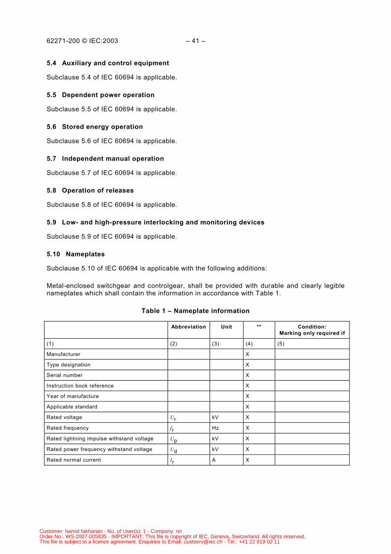
5.10 Nameplates
Subclause 5.10 of IEC 60694 is applicable with the following additions:
Metal-enclosed switchgear and controlgear, shall be provided with durable and clearly legiblenameplates which shall contain the information in accordance with Table 1.
Table 1 – Nameplate information
Abbreviation Unit ** Condition:Marking only required if
(1) (2) (3) (4) (5)
Manufacturer X
Type designation X
Serial number X
Instruction book reference X
Year of manufacture X
Applicable standard X
Rated voltage Ur kV X
Rated frequency fr Hz X
Rated lightning impulse withstand voltage Up kV X
Rated power frequency withstand voltage Ud kV X
Rated normal current Ir A X
Customer: hamid fakharian - No. of User(s): 1 - Company: nriOrder No.: WS-2007-005835 - IMPORTANT: This file is copyright of IEC, Geneva, Switzerland. All rights reserved.This file is subject to a licence agreement. Enquiries to Email: [email protected] - Tel.: +41 22 919 02 11
62271-200 © IEC:2003 – 43 –
Abbreviation Unit ** Condition:Marking only required if
Rated short-time withstand current(for main and earthing circuits)
Ik kA X
Rated peak withstand current(for main and earthing circuits)
Ip kA Y Different from 2,5 for 50Hz and 2,6 for 60 Hz
Rated duration of short circuit(for main and earthing circuits)
tk s X
Rated filling level for insulation pre Pa or kg (X)
Alarm level for insulation pae Pa or kg (X)
Minimum functional level for insulation pme Pa or kg (X)
Insulating fluid and mass kg (X)
Internal arc classification IAC (X)
Accessibility type (code) A(F,L,R),B(F,L,R) orC
(X)
Arc test current kA (X)
Arc test current duration s (X)
(**) X = the marking of these values is mandatory;
(X) = the marking of these values is as applicable;
y = conditions for marking of these values are given in column 5.
NOTE 1 The abbreviation in column (2) may be used instead of the terms in column (1).
NOTE 2 When terms in column (1) are used, the word “rated” need not appear.
The nameplates of each functional unit shall be legible during normal service. The removableparts, if any, shall have a separate nameplate with the data relating to the functional units theybelong to, but this nameplate need only be legible when the removable part is in the removedposition.
5.11 Interlocking devices
Subclause 5.11 of IEC 60694 is applicable with the following additions:
Interlocks between different components of the equipment are provided for reasons ofprotection and for convenience of operation. The following provisions are mandatory for maincircuits.
a) Metal-enclosed switchgear and controlgear with removable partsThe withdrawal or engagement of a circuit-breaker, switch or contactor shall be preventedunless it is in the open position.The operation of a circuit-breaker, switch or contactor shall be prevented unless it is only inthe service, disconnected, removed, test or earthing position.The interlock shall prevent the closing of the circuit-breaker, switch or contactor in theservice position unless any auxiliary circuits associated with the automatic opening of thesedevices are connected. Conversely, it shall prevent the disconnection of the auxiliarycircuits with the circuit-breaker closed in the service position.
Customer: hamid fakharian - No. of User(s): 1 - Company: nriOrder No.: WS-2007-005835 - IMPORTANT: This file is copyright of IEC, Geneva, Switzerland. All rights reserved.This file is subject to a licence agreement. Enquiries to Email: [email protected] - Tel.: +41 22 919 02 11
62271-200 © IEC:2003 – 45 –
b) Metal-enclosed switchgear and controlgear provided with disconnectorsInterlocks shall be provided to prevent operation of disconnectors under conditions otherthan those for which they are intended (refer to IEC 62271-102). The operation of adisconnector shall be prevented unless the circuit-breaker, switch or contactor is in theopen position.NOTE 1 This rule may be disregarded if it is possible to have a busbar transfer in a double busbar systemwithout current interruption.
The operation of the circuit-breaker, switch or contactor shall be prevented unless theassociated disconnector is in the closed, open or earthing position (if provided).The provision of additional or alternative interlocks shall be subject to agreement betweenmanufacturer and user. The manufacturer shall give all necessary information on thecharacter and function of interlocks.Earthing switches having a rated short-circuit making capacity less than the rated peakwithstand current of the main circuit should be interlocked with the associateddisconnectors.Apparatus installed in main circuits, the incorrect operation of which can cause damage orwhich are used for securing isolating distances during maintenance work, shall be providedwith locking facilities (for example, provision for padlocks).If earthing of a circuit is provided by the main switching device (circuit-breaker, switch orcontactor) in series with an earthing switch, the earthing switch shall be interlocked with themain switching device. Provision shall be made for the main switching device to be securedagainst unintentional opening, for example, by disconnection of tripping circuits andblocking of the mechanical trip.NOTE 2 Instead of an earthing switch, also a disconnector in the earthing position is possible.
If non-mechanical interlocks are provided, the design shall be such that no impropersituations can occur in case of lack of auxiliary supply. However, for emergency control, themanufacturer may provide additional means for manual operation without interlockingfacilities. In such case, the manufacturer shall clearly identify this facility and define theprocedures for operation.
5.12 Position indication
Subclause 5.12 of IEC 60694 is applicable.
5.13 Degrees of protection by enclosures
Subclause 5.13 of IEC 60694 is applicable.
5.14 Creepage distances
Subclause 5.14 of IEC 60694 is applicable.
5.15 Gas and vacuum tightness
Subclause 5.15 of IEC 60694 is applicable with the following addition:
Refer to 5.103.2.3.
Customer: hamid fakharian - No. of User(s): 1 - Company: nriOrder No.: WS-2007-005835 - IMPORTANT: This file is copyright of IEC, Geneva, Switzerland. All rights reserved.This file is subject to a licence agreement. Enquiries to Email: [email protected] - Tel.: +41 22 919 02 11
62271-200 © IEC:2003 – 47 –
5.16 Liquid tightness
Subclause 5.16 of IEC 60694 is applicable with the following addition:
Refer to 5.103.2.3.
5.17 Flammability
Subclause 5.17 of IEC 60694 is applicable.
5.18 Electromagnetic compatibility (EMC)
Subclause 5.18 of IEC 60694 is applicable.
5.101 Internal fault
Metal-enclosed switchgear and controlgear that satisfy the requirements of this standard isdesigned and manufactured, in principle, to prevent the occurrence of internal faults.
The user shall make a proper selection, according to the characteristics of the network,operating procedures and service conditions (refer to 8.3).
If the switchgear and controlgear is installed, operated and maintained following theinstructions of the manufacturer, there should be little probability that an internal arc occursduring its entire service life, but it cannot be completely disregarded.
Failure within the enclosure of metal-enclosed switchgear and controlgear due either to adefect or an exceptional service condition or maloperation may initiate an internal arc, whichconstitutes a hazard, if persons are present.
Experience has shown that faults are more likely to occur in some locations inside anenclosure than in others. Table 2 in Clause 8 gives a list of such locations, causes of failureand possible measures to decrease the probability of internal faults.
Other measures may be adopted to provide the highest possible level of protection to personsin case of an internal arc. These measures are aimed to limit the external consequences ofsuch an event.
The following are some examples of these measures.
− Rapid fault-clearance times initiated by detectors sensitive to light, pressure or heat or by adifferential busbar protection.
− Application of suitable fuses in combination with switching devices to limit the let-throughcurrent and fault duration.
− Fast elimination of arc by diverting it to metallic short circuit by means of fast sensing andfast closing devices (arc eliminator).
− Remote control.
− Pressure relief device.
− Transfer of a withdrawable part to or from the service position only when the front door isclosed.
The effectiveness of the design, at providing the prescribed level of protection of persons incase of an internal arc, can be verified by testing according to Annex A. Designs which havebeen successfully tested qualify as IAC classified.
Customer: hamid fakharian - No. of User(s): 1 - Company: nriOrder No.: WS-2007-005835 - IMPORTANT: This file is copyright of IEC, Geneva, Switzerland. All rights reserved.This file is subject to a licence agreement. Enquiries to Email: [email protected] - Tel.: +41 22 919 02 11
62271-200 © IEC:2003 – 49 –
5.102 Enclosure
5.102.1 General
Enclosures shall be metallic. External parts of the switchgear and controlgear may be ofinsulating material, provided that HV parts are completely enclosed by metallic partitions orshutters intended to be earthed. Excepted are inspection windows complying with 5.102.4.When the metal-enclosed switchgear and controlgear is installed, the enclosure shall provideat least the degree of protection IP 2X, according to IEC 60694, Table 6. It shall also ensureprotection in accordance with the following conditions.
Metallic parts of the enclosures shall be designed to carry 30 A (d.c.) with a voltage drop ofmaximum 3 V to the earthing point provided. The floor surface, even if not metallic, may beconsidered as part of the enclosure. The measures to be taken in order to obtain the degree ofprotection provided by floor surfaces shall be given in the installation manual.
The walls of a room shall not be considered as parts of the enclosure.
Parts of the enclosure bordering non-accessible compartments shall be provided with a clearindication not to be dismantled
The horizontal surfaces of enclosures, for example, roof plates, are normally not designed tosupport personnel or additional equipment not supplied as part of the assembly. If themanufacturer states that it is necessary to stand or walk upon the switchgear or controlgearduring operation or maintenance, the design shall be such that the relevant areas will supportthe weight of the operator without undue distortion and the equipment will remain suitable forits purpose. In such case, those areas on the equipment where it is not safe to stand or walk,for example, pressure relief flaps, shall be clearly identified.
5.102.2 Covers and doors
Covers and doors that are parts of the enclosure shall be metallic. Excepted are covers anddoors that may be of insulating material, provided that HV parts are enclosed by metallicpartitions or shutters intended to be earthed.
When covers and doors that are parts of the enclosure are closed, they shall provide thedegree of protection specified for the enclosure.
Covers or doors shall not be made of woven wire mesh, expanded metal or similar. Whenventilating openings, vent outlets or inspection windows are incorporated in the cover or door,reference is made to 5.102.4/5.
Several categories of covers or doors are recognized with regard to the type of accessiblecompartments they provide access to.
a) Covers or doors that give access to tool-based accessible compartmentsThese covers or doors need not be opened for the normal purposes of operation ormaintenance (fixed covers). It shall not be possible for them to be opened, dismantled orremoved without the use of tools;NOTE 1 They should be opened only when precautions to ensure electrical safety have been taken.
NOTE 2 Attention should be paid to the requirement (if any) to carry out operation of the switching deviceswithout voltage/current on the main circuit with doors and covers open as part of the maintenance procedures.
b) Covers or doors that give access to interlock-controlled accessible or procedure-basedaccessible compartmentsThese covers or doors shall be provided if there is a need to access the compartment fornormal operation and/or normal maintenance as stated by the manufacturer. These coversor doors shall not require tools for their opening or removal and shall have the followingfeatures:
Customer: hamid fakharian - No. of User(s): 1 - Company: nriOrder No.: WS-2007-005835 - IMPORTANT: This file is copyright of IEC, Geneva, Switzerland. All rights reserved.This file is subject to a licence agreement. Enquiries to Email: [email protected] - Tel.: +41 22 919 02 11
62271-200 © IEC:2003 – 51 –
– interlock controlled accessible compartments.These compartments shall be provided with interlocking devices so that opening of thecompartment shall only be possible when the part of the main circuit contained in thecompartment being made accessible is dead and earthed, or in the disconnectedposition with corresponding shutters closed;
– procedure-based accessible compartments.These compartments shall be provided with provision for locking, for example,padlocking.
NOTE 3 Suitable procedures should be put in place by the user to ensure that a procedure-based accessiblecompartment may be opened only when the part of the main circuit contained in the compartment being madeaccessible is dead and earthed, or in the disconnected position with corresponding shutters closed. Proceduresmay be dictated by legislation of the country of installation or by user safety documentation.
5.102.3 Partition or shutter being part of the enclosure
If partitions or shutters become part of the enclosure with the removable part in any of thepositions defined in 3.127 to 3.130, they shall be metallic, earthed and provide the degree ofprotection specified for the enclosure.
NOTE 1 A partition or shutter becomes a part of the enclosure if it is accessible in any of the positions defined in3.127 to 3.130 and if no door is provided which can be closed in the positions defined in 3.126 to 3.130.
NOTE 2 If a door is provided which can be closed in the positions defined in 3.126 to 3.130, the partition or shutterbehind the door is not considered to be a part of the enclosure.
5.102.4 Inspection windows
Inspection windows shall provide at least the degree of protection specified for the enclosure.
They shall be covered by a transparent sheet of mechanical strength comparable to that of theenclosure. Precautions shall be taken to prevent the formation of dangerous electrostaticcharges, either by clearance or by electrostatic shielding (for example, a suitable earthedwire-mesh on the inside of the window).
The insulation between live parts of the main circuit and the accessible surface of theinspection windows shall withstand the test voltages specified in 4.2 of IEC 60694 for voltagetests to earth and between poles.
5.102.5 Ventilating openings, vent outlets
Ventilating openings and vent outlets shall be so arranged or shielded that the same degree ofprotection as that specified for the enclosure is obtained. Such openings may make use of wiremesh or the like provided that it is of suitable mechanical strength.
Ventilating openings and vent outlets shall be arranged in such a way that gas or vapourescaping under pressure does not endanger the operator.
5.103 Compartments
5.103.1 General
A compartment shall be designated by the main component contained therein, for example,circuit-breaker compartment, busbar compartment, cable compartment, etc.
Customer: hamid fakharian - No. of User(s): 1 - Company: nriOrder No.: WS-2007-005835 - IMPORTANT: This file is copyright of IEC, Geneva, Switzerland. All rights reserved.This file is subject to a licence agreement. Enquiries to Email: [email protected] - Tel.: +41 22 919 02 11
62271-200 © IEC:2003 – 53 –
Where cable terminations are contained in a compartment with other main components (forexample, circuit-breaker, busbars, etc.) then the designation shall primarily be that of the othermain component.
NOTE Compartments may be further identified according to the several components enclosed, for example,cable/CT compartment, etc.
Compartments may be of various types, for example:
– liquid-filled;– gas-filled;– solid-insulation.
Main components individually embedded in solid insulating material may be considered ascompartments, provided that the conditions specified in IEC 60466 are met.
Openings necessary for interconnection between compartments shall be closed with bushingsor other equivalent means.
Busbar compartments may extend through several functional units without the need forbushings or other equivalent means. However, in case of LSC2, separate compartments shallbe provided for each set of busbars, for example, in double busbar systems and for sections ofswitchable or disconnectable busbars.
5.103.2 Fluid-filled compartments (gas or liquid)
5.103.2.1 General
Compartments shall be capable of withstanding the normal and transient pressures to whichthey are subjected in service.
Gas-filled compartments, when permanently pressurized in service, are subjected to particularconditions of service which distinguish them from compressed air receivers and similar storagevessels. These conditions are as follows.
− Gas-filled compartments are normally filled with a non-corrosive gas, thoroughly dried,stable and inert; since measures to maintain the gas in this condition with only smallfluctuations in pressure are fundamental to the operation of the switchgear and controlgearand since the compartments will not be subjected to internal corrosion, there is no need tomake allowances for these factors in determining the design of the compartments.
− The design pressure is below, or equal to, 300 kPa (relative pressure).
For outdoor installations, the manufacturer shall take into account the influence of climaticconditions (refer to Clause 2 of IEC 60694).
5.103.2.2 Design
The design of a fluid-filled compartment shall be based on the nature of the fluid, the designtemperature and when applicable, on the design level as defined in this standard.
The design temperature of the fluid-filled compartment is generally the upper limit of ambientair temperature increased by the temperature rise of the fluid due to the flow of rated normalcurrent. For outdoor installations, other possible influences, such as solar radiation, shall betaken into account. The design pressure of the enclosure shall not be less than the upper limitof the pressure reached within the enclosure at the design temperature.
Customer: hamid fakharian - No. of User(s): 1 - Company: nriOrder No.: WS-2007-005835 - IMPORTANT: This file is copyright of IEC, Geneva, Switzerland. All rights reserved.This file is subject to a licence agreement. Enquiries to Email: [email protected] - Tel.: +41 22 919 02 11
62271-200 © IEC:2003 – 55 –
Account shall be taken of the possibility of the occurrence of an internal fault (refer to 5.101)and the following for fluid-filled compartments:
a) the full differential pressure possible across the compartment walls or partitions, includingany evacuation process if used during filling or maintenance operations;
b) the resulting pressure in the event of an accidental leak between the compartments in thecase of adjacent compartments having different service pressures.
5.103.2.3 Tightness
The manufacturer shall state the pressure system used and the permissible leakage rate forthe fluid-filled compartments (refer to 5.15 and 5.16 of IEC 60694).
If requested by the user, in order to permit entry to a fluid-filled compartment of closed orcontrolled pressure systems, the permissible leakage across partitions should also be stated bythe manufacturer.
For gas-filled compartments where the minimum functional level exceeds 100 kPa (relativepressure) an indication should be provided when the pressure at 20 °C has fallen below theminimum functional level (refer to 3.120).
A partition, separating a compartment filled with insulating gas from a neighbouringcompartment filled with liquid, such as a cable box or a voltage transformer, shall not show anyleakage affecting the dielectric properties of the two media.
5.103.2.4 Pressure relief of fluid-filled compartments
Where pressure-relief devices or designs are provided, they shall be arranged so as tominimize the danger to an operator during the time that he is performing his normal operatingduties if gases or vapours are escaping under pressure. The pressure relief devices shall notoperate below 1,3 times the design pressure. The pressure relief device may be a designed,for example, weak area, of the compartment or a dedicated device, for example, bursting disk.
5.103.3 Partitions and shutters
5.103.3.1 General
Partitions and shutters shall provide at least the degree of protection IP2X according toIEC 60529.
Partitions shall provide mechanical protection against the normal gas pressure still present inthe adjacent compartment (if applicable).
Conductors passing through partitions shall be provided with bushings or other equivalentmeans to provide the required IP level.
Openings in the enclosure of metal-enclosed switchgear and controlgear and in the partitionsof compartments through which contacts of removable or withdrawable parts engage fixedcontacts shall be provided with automatic shutters operated in normal service operations toassure the protection of persons in any of the positions defined in 3.126 to 3.130. Means shallbe provided to ensure the reliable operation of the shutters, for example, by a mechanicaldrive, where the movement of the shutters is positively driven by the movement of theremovable or withdrawable part.
Customer: hamid fakharian - No. of User(s): 1 - Company: nriOrder No.: WS-2007-005835 - IMPORTANT: This file is copyright of IEC, Geneva, Switzerland. All rights reserved.This file is subject to a licence agreement. Enquiries to Email: [email protected] - Tel.: +41 22 919 02 11
62271-200 © IEC:2003 – 57 –
The status of shutters may not in all situations be readily confirmed from an open compart-ment, (for example, cable compartment open but shutters mounted in breaker compartment).In such situations, verification of the shutter status may require access to the secondcompartment or provision of an inspection window or reliable indicating device.
If, for maintenance or test purposes, there is a requirement that one or more sets of fixedcontacts shall be accessible through opened shutters, the shutters shall be provided withmeans of locking each set independently in the closed position. When, for maintenance or testpurposes, the automatic closing of shutters is made inoperative in order to retain them in theopen position, it shall not be possible to return the switching device to the service position untilthe automatic operation of the shutters is restored. This restoration may be achieved by theaction of returning the switching device to the service position.
It may be possible to use a temporary inserted partition to prevent the live set of fixed contactsbeing exposed (refer to 10.4).
For class PM, partitions and shutters between opened compartments and live parts of the maincircuit, shall be metallic; otherwise, the class is PI (refer to 3.109).
5.103.3.2 Metallic partitions and shutters
Metallic partitions and shutters or metallic parts of them shall be connected to the earthingpoint of the functional unit and be designed to carry 30 A (d.c.) with a voltage drop of less than3 V to the earthing point provided.
Discontinuity in the metallic partitions and closed shutters shall not exceed 12,5 mm to be inline with degree of protection IP2X.
5.103.3.3 Non-metallic partitions and shutters
Non-metallic partitions and shutters, made or partly made of insulating material, shall meet thefollowing requirements.
a) The insulation between live parts of the main circuit and the accessible surface of insulatingpartitions and shutters shall withstand the test voltages specified in 4.2.1 of IEC 60694 forvoltage tests to earth and between poles.
b) The insulating material shall withstand the power-frequency test voltage specified initem a). The appropriate test methods given in IEC 60243-1 should be applied.
c) The insulation between live parts of the main circuit and the inner surface of insulatingpartitions and shutters facing these shall withstand at least 150 % of the rated voltage ofthe equipment.
d) If a leakage current may reach the accessible side of the insulating partitions and shuttersby a continuous path over insulating surfaces or by a path broken only by small gaps of gasor liquid, it shall be not greater than 0,5 mA under the specified test conditions (refer to6.104.2).
5.104 Removable parts
Removable parts for ensuring the isolating distance between the high-voltage conductors shallcomply with IEC 62271-102, except for mechanical operation tests (refer to 6.102 and 7.102).This disconnection facility is intended for maintenance purposes only.
If removable parts are intended to be used as a disconnector or intended to be removed andreplaced more often than only for maintenance purposes, then testing shall also include themechanical operation tests according to IEC 62271-102.
Customer: hamid fakharian - No. of User(s): 1 - Company: nriOrder No.: WS-2007-005835 - IMPORTANT: This file is copyright of IEC, Geneva, Switzerland. All rights reserved.This file is subject to a licence agreement. Enquiries to Email: [email protected] - Tel.: +41 22 919 02 11
62271-200 © IEC:2003 – 59 –
The requirement that it shall be possible to know the operating position of the disconnector orearthing switch is met if one of the following conditions is fulfilled.
– The isolating distance is visible.– The position of the withdrawable part, in relation to the fixed part, is clearly visible and the
positions corresponding to full connection and full isolation are clearly identified.– The position of the withdrawable part is indicated by a reliable indicating device.NOTE 1 In some countries, regulations require that the isolating distance is visible.
NOTE 2 Refer to IEC 62271-102.
Any removable part shall be so attached to the fixed part that its contacts will not openinadvertently due to forces which may occur in service, in particular those due to a short circuit.
In switchgear and controlgear IAC classified, the transfer of withdrawable parts to or fromservice position shall be carried out without reduction of the specified level of protection in theevent of an internal arc. This is achieved, for example, when the operation is only possiblewhen doors and covers intended to ensure personnel protection are closed. Other designmeasures providing equivalent level of protection are acceptable. The effectiveness of theadopted design shall be verified by testing (see Clause A.1).
5.105 Provisions for dielectric tests on cables
When it is not practical to disconnect the cable for the dielectric tests from the metal-enclosedswitchgear and controlgear, those parts which remain connected to the cable shall be capableof withstanding the cable test voltages as stated by the manufacturer and based upon therelevant cable standards. That is, when one side of the isolating gap is energized at normalsystem voltage to earth and tests are being carried out on the cable connected to the otherside of the isolating gap.
Refer to the dielectric test defined in 6.2.101.
NOTE Attention is drawn to the fact that practically no safety margin is left in some cases between the ratedpower-frequency test voltage for the isolating distance and the resulting voltage stress across the isolating distancedue to the application of the cable test voltage if the other side of the isolating distance of metal-enclosedswitchgear and controlgear is still live.
6 Type tests
6.1 General
Subclause 6.1 of IEC 60694 is applicable with following additions:
Components contained in metal-enclosed switchgear and controlgear which are subject toindividual specifications not covered by the scope of IEC 60694 shall comply with and be testedin accordance with those specifications, taking into account the following subclauses.
The type tests shall be made on a representative functional unit. Because of the variety oftypes, ratings and possible combinations of components, it is not practicable to make type testswith all the arrangements of metal-enclosed switchgear and controlgear. The performance ofany particular arrangement may be substantiated by test data of comparable arrangements.
NOTE A representative functional unit may take the form of one extensible unit. However, it may be necessary tobolt two or three of such units together.
Customer: hamid fakharian - No. of User(s): 1 - Company: nriOrder No.: WS-2007-005835 - IMPORTANT: This file is copyright of IEC, Geneva, Switzerland. All rights reserved.This file is subject to a licence agreement. Enquiries to Email: [email protected] - Tel.: +41 22 919 02 11
62271-200 © IEC:2003 – 61 –
The type tests and verifications comprise:
Mandatory type tests:
a) Tests to verify the insulation level of the equipment (see 6.2)b) Tests to prove the temperature rise of any part of the equipment and measurement of the
resistance of circuits (see 6.5 and 6.4)c) Tests to prove the capability of the main and earthing circuits to be subjected to the rated
peak and the rated short-time withstand currents (see 6.6)d) Test to prove the making and breaking capacity of the included switching devices (see
6.101)e) Tests to prove the satisfactory operation of the included switching devices and removable
parts (see 6.102)f) Tests to verify the protection of persons against access to hazardous parts and the
protection of the equipment against solid foreign objects (see 6.7).
Mandatory type tests, where applicable:
g) Tests to verify the protection of persons against dangerous electrical effects (see 6.104)h) Tests to verify the strength of gas-filled compartments (see 6.103)i) Tightness tests of gas- or liquid-filled compartments (see 6.8)j) Tests to assess the effects of arcing due to an internal fault (for switchgear and controlgear
classification IAC) (see 6.106)k) Electromagnetic compatibility tests (EMC) (see 6.9).
Optional type tests (subject to agreement between manufacturer and user):
l) Tests to verify the protection of the equipment against external effects due to weather (see6.105)
m) Tests to verify the protection of the equipment against mechanical impact (see 6.7)n) Tests to evaluate the insulation of the equipment by the measurement of partial discharges
(see 6.2.9)o) Artificial pollution tests (see 6.2.8)p) Dielectric tests on cable testing circuits (see 6.2.101).
Type tests may impair the suitability of the tested parts for subsequent use in service.Therefore, specimens used for type test shall not be used in service without agreementbetween manufacturer and user.
6.1.1 Grouping of tests
Subclause 6.1.1 of IEC 60694 is applicable with the following modifications:
The mandatory type tests (not including items j) and k)) shall be carried out on a maximum offour test specimens.
6.1.2 Information for identification of specimens
Subclause 6.1.2 of IEC 60694 is applicable.
6.1.3 Information to be included in type-test reports
Subclause 6.1.3 of IEC 60694 is applicable.
Customer: hamid fakharian - No. of User(s): 1 - Company: nriOrder No.: WS-2007-005835 - IMPORTANT: This file is copyright of IEC, Geneva, Switzerland. All rights reserved.This file is subject to a licence agreement. Enquiries to Email: [email protected] - Tel.: +41 22 919 02 11
62271-200 © IEC:2003 – 63 –
6.2 Dielectric tests
Subclause 6.2 of IEC 60694 is applicable.
6.2.1 Ambient air conditions during tests
Subclause 6.2.1 of IEC 60694 is applicable.
6.2.2 Wet test procedure
Not applicable, as no dielectric tests under wet conditions are necessary for metal-enclosedswitchgear and controlgear.
6.2.3 Conditions of metal-enclosed switchgear and controlgear during dielectric tests
Subclause 6.2.3 of IEC 60694 is applicable with the following addition:
For metal-enclosed switchgear and controlgear using fluid (liquid or gas) for insulation,dielectric tests shall be performed filled with the insulating fluid specified by the manufacturer,to the minimum functional level also specified by the manufacturer.
6.2.4 Criteria to pass the test
Subclause 6.2.4 of IEC 60694 is applicable, with the following modifications:
– the second paragraph of item a) that refers to wet test is not applicable;– the first paragraph of item b) is replaced by
The switchgear and controlgear has passed the impulse tests if the following conditions arefulfilled:a) the number of disruptive discharges do not exceed two for each series of 15 impulses;b) no disruptive discharges on non-self-restoring insulation occur.This is verified by at least five impulses without disruptive discharge following that impulsewhich caused the last disruptive discharge. If this impulse is one of the last five out of theseries of 15 impulses, additional impulses shall be applied, provided that the total numberof discharges does not exceed two in the complete series. This can result in a maximum of 25impulses per series.NOTE 1 For fluid-filled compartments tested with test bushings that are not part of the switchgear andcontrolgear, impulses resulting in flashover across the test bushings are not considered as part of the testseries.
6.2.5 Application of the test voltage and test conditions
Subclause 6.2.5 of IEC 60694 is not applicable.
Because of the great variety of designs, it is not feasible to give specific indications of the teststo be performed on the main circuit, but, in principle, they shall cover the following tests.
a) To earth and between phasesThe test voltages specified in 6.2.6 shall be applied connecting each phase conductor ofthe main circuit in turn to the high-voltage terminal of the test supply. All other conductorsof the main circuit and the auxiliary circuits shall be connected to the earthing conductor orthe frame and to the earth terminal of the test supply.If the phase conductors are segregated, only tests to earth apply.
Customer: hamid fakharian - No. of User(s): 1 - Company: nriOrder No.: WS-2007-005835 - IMPORTANT: This file is copyright of IEC, Geneva, Switzerland. All rights reserved.This file is subject to a licence agreement. Enquiries to Email: [email protected] - Tel.: +41 22 919 02 11
62271-200 © IEC:2003 – 65 –
The dielectric tests shall be made with all switching devices closed and all removable partsin their service position. Attention shall be given to the possibility that switching devices intheir open position or removable parts in the disconnected, removed, test or earthingposition may result in less favourable field conditions. Under such conditions the tests shallbe repeated. However, the removable parts shall not be subjected to these voltage testswhilst they are in the disconnected, test or removed position.For these tests, devices such as current transformers, cable terminations, overcurrentreleases/indicators shall be installed as in normal service. In case of doubt about the mostunfavourable arrangement, tests shall be repeated with alternative configurations.In order to check compliance with the requirements of 5.102.4 and item a) of 5.103.3.3,inspection windows, partitions and shutters of insulating material shall be covered on theside accessible during operation or maintenance, in the most unfavourable situation for thetest, with a circular or square metal foil having an area as large as possible but notexceeding 100 cm2 which shall be connected to earth. In case of doubt about the mostunfavourable situation, the tests shall be repeated with different situations. For convenienceof testing, subject to agreement between testing station and manufacturer, more than onemetal foil may be applied simultaneously or larger parts of the insulating material may becovered.
b) Across the isolating distanceEach isolating distance of the main circuit shall be tested using the test voltages specifiedin 6.2.6. according to the test procedures as stated in 6.2.5.2 of IEC 60694.The isolating distance may be formed by– a disconnector in open position;– the distance between the two parts of the main circuit intended to be connected by a
withdrawn or removed switching device.If, in the disconnected position, an earthed metallic shutter is interposed between thedisengaged contacts to assure a segregation, the gap between the earthed metallic shutterand the live parts shall withstand only the test voltages required to earth.If, in the disconnected position, there is no earthed metallic shutter or partition between thefixed part and the withdrawable part, the test voltages specified across the isolatingdistance shall be applied– between the fixed and moving contacts intended to engage, if conductive parts of the
main circuit of the withdrawable part can inadvertently be touched;– between the fixed contacts on one side and the fixed contacts on the other side, with
the switching device of the withdrawable part in the closed position if possible, if theycannot inadvertently be touched. If it is not possible to have the switching device closedin the disconnected position, then this test shall be repeated in the test position with theswitching device of the withdrawable part closed.
c) Complementary testsIn order to check compliance with the requirement of item c) of 5.103.3.3, the insulationbetween the live parts of the main circuit and the inside of insulating partitions or shuttersshall be subjected to a power-frequency test voltage of 150 % of the rated voltage for 1 minafter covering the inner surface of the partition or shutter facing the live parts by an earthedmetal foil as described under a) above.
Customer: hamid fakharian - No. of User(s): 1 - Company: nriOrder No.: WS-2007-005835 - IMPORTANT: This file is copyright of IEC, Geneva, Switzerland. All rights reserved.This file is subject to a licence agreement. Enquiries to Email: [email protected] - Tel.: +41 22 919 02 11
62271-200 © IEC:2003 – 67 –
6.2.6 Tests of metal-enclosed switchgear and controlgear
The tests shall be performed with the applicable test voltages given in Table 1a or 1b of 4.2 ofIEC 60694. For test voltages to earth and between phases, columns (2) and (4) shall be used.For test voltages across isolating distances columns (3) and (5) shall be used.
6.2.6.1 Power-frequency voltage tests
Switchgear and controlgear shall be subjected to short-duration power-frequency voltagewithstand tests in accordance with IEC 60060-1. The test voltage shall be raised for each testcondition to the test value and maintained for 1 min.
The tests shall be performed in dry conditions.
Instrument transformers, power transformers or fuses may be replaced by replicas reproducingthe field configuration of the high-voltage connections. Overvoltage protective devices may bedisconnected or removed.
During the power-frequency voltage tests, one terminal of the test transformer shall beconnected to earth and to the enclosure of the metal-enclosed switchgear and controlgear,except that during the tests, in accordance with item b) of 6.2.5, the mid-point or anotherintermediate point of the voltage source should be connected to earth and to the enclosure inorder that the voltage appearing between any of the live parts and the enclosure will notexceed the test voltage specified in item a) of 6.2.5.
If this is not practicable, one terminal of the test transformer may, with the agreement of themanufacturer, be connected to earth and the enclosure shall, if necessary, be insulated fromearth.
6.2.6.2 Lightning impulse voltage tests
Switchgear and controlgear shall be subjected to lightning impulse voltage tests in dryconditions only. Procedure B of IEC 60060-1 shall be applied using the standard lightningimpulse 1,2/50 µs. Fifteen consecutive lightning impulses at the rated withstand voltage shallbe applied for each test condition and each polarity.
Instrument transformers, power transformers or fuses may be replaced by replicas reproducingthe field configuration of the high-voltage connections.
Overvoltage protective devices shall be disconnected or removed. Current transformersecondaries shall be short-circuited and earthed. Current transformers with a low ratio mayhave their primaries short-circuited too.
During the lightning impulse voltage tests, the earthed terminal of the impulse generator shallbe connected to the enclosure of the metal-enclosed switchgear and controlgear, except thatduring the tests in accordance with item b) of 6.2.5, the enclosure shall, if necessary, beinsulated from earth in order that the voltage appearing between any of the live parts and theenclosure will not exceed the test voltage specified in item a) of 6.2.5.
6.2.7 Tests of switchgear and controlgear of rated voltage above 245 kV
Not applicable.
Customer: hamid fakharian - No. of User(s): 1 - Company: nriOrder No.: WS-2007-005835 - IMPORTANT: This file is copyright of IEC, Geneva, Switzerland. All rights reserved.This file is subject to a licence agreement. Enquiries to Email: [email protected] - Tel.: +41 22 919 02 11
62271-200 © IEC:2003 – 69 –
6.2.8 Artificial pollution tests
Metal-enclosed switchgear and controlgear intended to be used in service conditions moresevere with respect to condensation and pollution than the normal service conditions specifiedin this standard may be submitted to test according to IEC 60932, upon agreement between themanufacturer and user.
6.2.9 Partial discharge tests
Refer to Annex B with the following additions:
This test is subject to agreement between manufacturer and user.
If the test is made, it shall be carried out after the lightning impulse and power-frequencyvoltage tests. Instrument transformers, power transformers or fuses may be replaced byreplicas reproducing the field configuration of the high-voltage connections.
NOTE 1 In the case of designs consisting of a combination of conventional components (for instance, instrumenttransformers, bushings) that can be tested separately in accordance with their relevant standards, the purpose ofthis partial discharge test is to check the arrangement of the components in the assembly.
NOTE 2 This test may be carried out on assemblies or subassemblies. Care should be taken that external partialdischarges do not affect the measurement.
6.2.10 Dielectric tests on auxiliary and control circuits
Subclause 6.2.10 of IEC 60694 is applicable.
Current transformer secondaries may be short-circuited and disconnected from earth. Voltagetransformer secondaries may be disconnected.
Voltage-limiting devices, if any, shall be disconnected.
6.2.11 Voltage test as condition check
Subclause 6.2.11 of IEC 60694 is applicable.
6.2.101 Dielectric tests on cable testing circuits
To allow dielectric tests on cables while the switchgear and controlgear is in service (refer to5.105), an additional power-frequency withstand voltage type test may be applied to confirm theability of the relevant isolating distances to withstand cable test voltage while the other side ofthe isolating distance is still live.
The test values are subject to agreement between the user and manufacturer.
NOTE The test values agreed should be chosen to ensure a safety margin between the rated power-frequency testvoltages for the isolating distance and the resulting voltage stress across the isolating distance due to theapplication of, for example, a d.c. cable test voltage while the other side of the isolating distance of metal-enclosedswitchgear and controlgear is still live.
6.3 Radio interference voltage (r.i.v.) test
Not applicable.
Customer: hamid fakharian - No. of User(s): 1 - Company: nriOrder No.: WS-2007-005835 - IMPORTANT: This file is copyright of IEC, Geneva, Switzerland. All rights reserved.This file is subject to a licence agreement. Enquiries to Email: [email protected] - Tel.: +41 22 919 02 11
62271-200 © IEC:2003 – 71 –
6.4 Measurement of the resistance of circuits
6.4.1 Main circuit
Subclause 6.4.1 of IEC 60694 is applicable with the following addition:
The measured resistance across the complete main circuit of an assembly of metal-enclosedswitchgear and controlgear is indicative of the proper condition of the current path. Thismeasured resistance shall be the reference for the routine test (refer to 7.3).
6.4.2 Auxiliary circuits
Subclause 6.4.2 of IEC 60694 is applicable.
6.5 Temperature-rise tests
Subclause 6.5 of IEC 60694 is applicable, with the following addition:
Where the design provides alternative components or arrangements, the test shall beperformed with those components or arrangements for which the most severe conditions areobtained. The representative functional unit shall be mounted approximately as in normalservice, including all normal enclosures, partitions, shutters, etc., and the covers and doorsclosed.
The tests shall be made normally with the rated number of phases and the rated normal currentflowing from one end of the length of busbars to the terminals provided for the connection ofcables.
When testing individual functional units, the neighbouring units should carry the currents whichproduce the power loss corresponding to the rated conditions. lt is admissible to simulateequivalent conditions by means of heaters or heat insulation, if the test cannot be performedunder actual conditions.
Where there are other main functional components installed within the enclosure, they shallcarry the currents which produce the power loss corresponding to the rated conditions.Equivalent procedures to generate the same power dissipation are acceptable.
The temperature rises of the different components shall be referred to the ambient airtemperature outside the enclosure and shall not exceed the values specified for them in therelevant standards. lf the ambient air temperature is not constant, the surface temperature ofan identical enclosure may be taken under the same ambient conditions.
6.5.1 Conditions of the metal-enclosed switchgear and controlgear to be tested
Subclause 6.5.1 of IEC 60694 is applicable.
6.5.2 Arrangement of the equipment
Subclause 6.5.2 of IEC 60694 is applicable.
6.5.3 Measurement of the temperature and the temperature rise
Subclause 6.5.3 of IEC 60694 is applicable.
Customer: hamid fakharian - No. of User(s): 1 - Company: nriOrder No.: WS-2007-005835 - IMPORTANT: This file is copyright of IEC, Geneva, Switzerland. All rights reserved.This file is subject to a licence agreement. Enquiries to Email: [email protected] - Tel.: +41 22 919 02 11
62271-200 © IEC:2003 – 73 –
6.5.4 Ambient air temperature
Subclause 6.5.4 of IEC 60694 is applicable.
6.5.5 Temperature-rise test of the auxiliary and control equipment
Subclause 6.5.5 of IEC 60694 is applicable.
6.5.6 Interpretation of the temperature-rise tests
Subclause 6.5.6 of IEC 60694 is applicable.
6.6 Short-time withstand current and peak withstand current tests
Subclause 6.6 of IEC 60694 is applicable, with the following addition:
a) Test on main circuitsMain circuits of metal-enclosed switchgear and controlgear shall be tested to verify theircapability to withstand the rated short-time and peak withstand current under the intendedconditions of installation and use, i.e. they shall be tested as installed in the metal-enclosedswitchgear and controlgear with all associated components influencing the performance ormodifying the short-circuit current.For these tests, short connections to auxiliary devices (such as voltage transformers,auxiliary transformers, surge arresters, surge capacitors, voltage detection devices, andsimilar items) are not considered as parts of the main circuit.The short-circuit current tests shall be carried out according to the rated number of phases.Current transformers and tripping devices that may be present shall be installed as innormal service, but with the release made inoperative.Equipment which does not include any current-limiting device may be tested at anyconvenient voltage. Equipment which incorporates a current-limiting device shall be testedat the rated voltage of the switchgear and controlgear. Other test voltages can be used, if itcan be demonstrated that both the applied peak current and resulting thermal effects areequal to, or higher than, those with rated voltage.For equipment including current-limiting devices the prospective current (peak, r.m.s valueand duration) shall not be less than the rated value.Self-tripping circuit-breakers, if any, shall be set on their maximum tripping values.Current-limiting fuses, if any, shall be provided with fuse-links having the maximum ratedcurrent specified.After the test, no deformation or damage to components or conductors within the enclosure,which may impair good operation of the main circuits, shall have been sustained.
b) Tests on earthing circuitsEarthing conductors, earthing connections and earthing devices of metal-enclosedswitchgear and controlgear shall be tested to verify their capability to withstand the ratedshort-time and peak withstand current under the neutral earthing condition of the system.That is, they shall be tested as installed in the metal-enclosed switchgear and controlgearwith all associated components influencing the performance or modifying the short-circuitcurrent.The short-circuit current tests with earthing devices shall be carried out according to therated number of phases. Further single-phase tests may be necessary in order to verify theperformance of all the circuits that are intended to provide the connection between theearthing device and earthing point provided.
Customer: hamid fakharian - No. of User(s): 1 - Company: nriOrder No.: WS-2007-005835 - IMPORTANT: This file is copyright of IEC, Geneva, Switzerland. All rights reserved.This file is subject to a licence agreement. Enquiries to Email: [email protected] - Tel.: +41 22 919 02 11
62271-200 © IEC:2003 – 75 –
When there are removable earthing devices, the earthing connection between the fixed partand the removable part shall be tested under earth-fault conditions. The earth-fault currentshall flow between the earthing conductor of the fixed part and the earthing point of theremovable part. Where the earthing device in the switchgear or controlgear can beoperated in alternative positions to the normal service position, for example, in doublebusbar switchgear and controlgear, a test shall be made in alternative positions.After the test some deformation and degradation of the earthing conductor, earthingconnections or earthing devices is permissible, but the continuity of the circuit shall bepreserved.Visual inspection should be sufficient to check that continuity of the circuit has beenpreserved.In case of doubt if certain earth connections are (still) adequate, the earthing shall beverified testing with 30 A (DC) to the earthing point provided. The voltage drop shall belower than 3 V.
6.6.1 Arrangement of the switchgear and controlgear and of the test circuit
Subclause 6.6.1 of IEC 60694 is applicable, with the following addition:
The equipment to be tested shall be arranged in such a way that the most onerous conditionsare obtained concerning the maximum lengths of unsupported busbar(s), configuration of theconductors and connections within the equipment. In the case of switchgear and controlgearincorporating double busbar systems and/or multi-tier designs, the tests shall be made with themost onerous position(s) of the switching device.
The test connections to the terminals of the switchgear and controlgear shall be arranged insuch a way as to avoid unrealistic stressing of, or support to, the terminals. The distancebetween the terminals and the nearest supports of the test conductors on both sides of theswitchgear and controlgear shall be in accordance with the instructions of the manufacturer buttaking into account the requirement above.
The switching devices shall be in the closed position and fitted with clean contacts in a newcondition.
Each test shall be preceded by a no-load operation of the mechanical switching device and,with the exception of earthing switches, by measurement of the resistance of the main circuit.
The test arrangement shall be noted in the test report.
6.6.2 Test current and duration
Subclause 6.6.2 of IEC 60694 is applicable.
6.6.3 Behaviour of switchgear and controlgear during test
Subclause 6.6.3 of IEC 60694 is applicable.
6.6.4 Conditions of switchgear and controlgear after test
Subclause 6.6.4 of IEC 60694 is applicable.
Customer: hamid fakharian - No. of User(s): 1 - Company: nriOrder No.: WS-2007-005835 - IMPORTANT: This file is copyright of IEC, Geneva, Switzerland. All rights reserved.This file is subject to a licence agreement. Enquiries to Email: [email protected] - Tel.: +41 22 919 02 11
62271-200 © IEC:2003 – 77 –
6.7 Verification of the protection
6.7.1 Verification of the IP coding
Subclause 6.7.1 of IEC 60694 is applicable, with the following addition:
The minimum degree of protection of the enclosure of the metal-enclosed switchgear andcontrolgear shall be IP2X in accordance with IEC 60529. A higher degree of protection may bespecified in accordance with IEC 60529.
6.7.2 Mechanical impact test
Subclause 6.7.2 of IEC 60694 is applicable.
6.8 Tightness tests
Subclause 6.8 of IEC 60694 is applicable.
6.9 Electromagnetic compatibility tests (EMC)
Subclause 6.9 of IEC 60694 is applicable, with exception of the radio interference voltage test.
6.10 Additional tests on auxiliary and control circuits
IEC 60694 is applicable for 6.10.1, 6.10.2, 6.10.4-7.
6.10.3 Electrical continuity of earthed metallic parts test
IEC 60694 is not applicable.
Generally no test is needed if adequate design is demonstrated.
However, in case of doubt, the metallic parts of the enclosures and/or metallic partitions andshutters or metallic parts of them shall be tested at 30 A (d.c.) to the earthing point provided.
The voltage drop shall be lower than 3 V.
6.101 Verification of making and breaking capacities
Switching devices forming part of the main circuit and earthing switches of metal-enclosedswitchgear and controlgear shall be tested to verify their rated making and breaking capacitiesaccording to the relevant standards and under the proper conditions of installation and use.That is, they shall be tested as normally installed in the metal-enclosed switchgear andcontrolgear with all associated components, the arrangement of which may influence theperformance, such as connections, supports, provisions for venting, etc. These tests are notnecessary if making and breaking tests have been performed on the switching devices installedin metal-enclosed switchgear and controlgear with more onerous conditions.
NOTE In determining which associated components are likely to influence the performance, special attentionshould be given to mechanical forces due to the short circuit, the venting of arc products, the possibility ofdisruptive discharges, etc. lt is recognized that, in some cases, such influence may be quite negligible.
Where multi-tier compartments of a multi-tier design are not identical but are designed toaccept the same switching device, the following tests/test-duties shall be repeated in eachcompartment as appropriate to the requirements of the relevant standard.
Customer: hamid fakharian - No. of User(s): 1 - Company: nriOrder No.: WS-2007-005835 - IMPORTANT: This file is copyright of IEC, Geneva, Switzerland. All rights reserved.This file is subject to a licence agreement. Enquiries to Email: [email protected] - Tel.: +41 22 919 02 11
62271-200 © IEC:2003 – 79 –
Where switching devices have previously been tested for short-circuit performance to theirrelevant standard within the enclosure of the metal enclosed switchgear and controlgear thenno further tests may be required.
Switchgear and controlgear, incorporating single or multi-tier design and/or double busbarsystems, requires special consideration for the test procedures applicable for the verification oftheir rated making and breaking capacities to cover combinations likely to be encountered inservice.
As it is not possible to cover all possible configurations and designs of switching devices, thefollowing procedures shall be followed, the precise combination of tests being determined bythe characteristics and location of the particular switching device being considered.
a) The complete appropriate making and breaking current test series shall be made with theswitching device in one of the compartments. lf other compartments are similar in design,and also the switching device intended for use in the compartment is identical, then thetests referred to above are also valid for these compartments.
b) Where the compartments are not similar but are designed to accept the same switchingdevice, the following tests/test duties are to be repeated in each of the other compartments,as appropriate to the requirements of the relevant standard:IEC 62271-100 test duty T100s, T100a, and critical current tests (if any) also taking intoaccount the requirements of 6.103.4 of the standard for the test connection arrangement,where applicable.IEC 62271-102 short-circuit making operations according class E1 or E2, as applicable.IEC 60265-1: 10 CO-operations with rated mainly active load breaking current (Test duty 1).Test duty 5 according to class E1, E2 or E3, as applicable, unless the switch does not havea rated short-circuit making capacity.IEC 62271-105:Test duties TDIsc, TDIWmax and TDItransfer.IEC 60470: Verification of coordination with SCPDs to 6.106 of IEC 60470.
c) Where compartments are designed to accept more than one particular type or design ofswitching device, each variant of switching device shall be fully tested in accordance withthe requirements of item a) and also, where appropriate item b) above.
6.102 Mechanical operation tests
6.102.1 Switching devices and removable parts
Switching devices and withdrawable parts shall be operated 50 times, and removable partsinserted 25 times and removed 25 times to verify satisfactory operation of the equipment.
If a withdrawable or removable part is intended to be used as a disconnector, then testing shallbe in accordance with IEC 62271-102.
6.102.2 Interlocks
The interlocks shall be set in the position intended to prevent the operation of the switchingdevices and the insertion or withdrawal of removable parts. Fifty attempts shall be made tooperate the switching devices and 25 attempts shall be made to insert and 25 attempts towithdraw the removable parts. During these tests only normal operating forces shall beemployed and no adjustment shall be made to the switching devices, removable parts orinterlocks. In case of manually operated equipment, the normal manual operation handle shallbe used to perform the tests.
Customer: hamid fakharian - No. of User(s): 1 - Company: nriOrder No.: WS-2007-005835 - IMPORTANT: This file is copyright of IEC, Geneva, Switzerland. All rights reserved.This file is subject to a licence agreement. Enquiries to Email: [email protected] - Tel.: +41 22 919 02 11
62271-200 © IEC:2003 – 81 –
The interlocks are considered to be satisfactory, ifa) the switching devices cannot be operated,b) the insertion and withdrawal of the removable parts are prevented,c) the switching devices, removable parts and the interlocks are in proper working order and
the effort to operate them is practically the same before and after the tests.
6.103 Pressure withstand test for gas-filled compartments
6.103.1 Pressure withstand test for gas-filled compartments with pressure reliefdevices
Each design of a gas-filled compartment shall be subjected to a pressure test according to thefollowing procedure.
– The relative pressure shall be increased in order to reach a value of 1,3 times the designpressure of the compartment for a period of 1 min. The pressure relief device shall notoperate.
– Then the pressure shall be increased up to a maximum value of three times the designpressure. It is acceptable that the pressure relief device may operate, as designed by themanufacturer, below this value. This opening pressure shall be recorded in the type testreport. After the test, the compartment may be distorted, but the compartment shall notrupture.
NOTE The relative withstand pressure of 3 times the design pressure may not be tested for the compartment,because it is not always possible to test without the presence of the pressure-relief device or a dedicated relief areaof the compartment wall.
6.103.2 Pressure withstand test for gas-filled compartments without pressure-reliefdevices
Each design of a gas-filled compartment shall be subjected to a pressure test according to thefollowing procedure.
– The relative pressure shall be increased up to three times the design pressure of thecompartment for 1 min. After the test, the compartment may be distorted, but thecompartment shall not rupture.
6.104 Tests on non-metallic partitions and shutters
This subclause applies only to partitions (and shutters) intended for protection from (direct andindirect) contact with live parts. When these partitions contain bushings, tests shall be carriedout under the appropriate conditions, i.e. with the primary parts of the bushings disconnectedand earthed.
Non-metallic partitions and shutters, made or partly made, of insulating material shall be testedas follows.
6.104.1 Dielectric tests
a) The insulation between live parts of the main circuit and the accessible surface ofinsulating partitions and shutters shall withstand the test voltages specified in 4.2 ofIEC 60694 for voltage tests to earth and between poles. For the test set-up, refer to itema) of 6.2.5.
b) A representative sample of the insulating material shall withstand the power-frequency testvoltage specified in item a). The appropriate test methods given in IEC 60243-1 should beapplied.
Customer: hamid fakharian - No. of User(s): 1 - Company: nriOrder No.: WS-2007-005835 - IMPORTANT: This file is copyright of IEC, Geneva, Switzerland. All rights reserved.This file is subject to a licence agreement. Enquiries to Email: [email protected] - Tel.: +41 22 919 02 11
62271-200 © IEC:2003 – 83 –
c) The insulation between live parts of the main circuit and the inner surface of insulatingpartitions and shutters facing these shall be tested at 150 % of the rated voltage of theequipment for 1 min. For the test, the inner surface of the partition or shutter shall beearthed by applying a conductive layer of at least 100 cm2, at the most onerous point. Thetest set-up shall be as specified in item a) of 6.2.5.
6.104.2 Measurements of leakage currents
When metal-enclosed switchgear and controlgear contains insulating partitions or shutter thefollowing tests shall be made in order to check compliance with the requirement of item d) of5.103.3.3.
The main circuit shall, at the discretion of the manufacturer, be connected either to a three-phase supply of power-frequency voltage equal to the rated voltage of the metal-enclosedswitchgear and controlgear, with one phase connected to earth, or to a single-phase supply ofa voltage equal to the rated voltage, the live parts of the main circuit being connected together.For three-phase tests, three measurements shall be made with the different phases of thesupply successively connected to earth. In the case of single-phase tests, only onemeasurement is necessary.
A metal foil shall be placed in the most unfavourable situation for the test on the accessiblesurface of the insulation providing the protection against contact with live parts. In case ofdoubt about the most unfavourable situation, the test shall be repeated with different situations.
The metal foil shall be approximately circular or square, having an area as large as possiblebut not exceeding 100 cm2. The enclosure and the frame of the metal-enclosed switchgear andcontrolgear shall be earthed. The leakage current flowing through the metal foil to earth shallbe measured with the insulation dry and clean.
If the value of the leakage current measured is more than 0,5 mA, the insulating surface doesnot provide the protection required in this standard.
If, as indicated in item d) of 5.103.3.3, the continuous path over insulating surfaces is brokenby small gaps of gas or liquid, such gaps shall be shorted out electrically. If these gaps areincorporated to avoid the passage of the leakage current from live parts to accessible parts ofinsulating partitions and shutters, the gaps shall withstand the test voltages specified in 4.2 ofIEC 60694 for voltage tests to earth and between poles.
It is not necessary to measure leakage currents, if earthed metal parts are arranged in anappropriate manner to ensure that leakage currents cannot reach the accessible parts of theinsulating partitions and shutters.
6.105 Weatherproofing test
When agreed between manufacturer and user, a weatherproofing test can be made on metal-enclosed switchgear and controlgear intended for outdoor use. A recommended method isgiven in Annex C of IEC 60694.
6.106 Internal arcing test
This test is applicable to metal-enclosed switchgear and controlgear, intended to be qualifiedas IAC classified with respect to personnel protection in the event of an internal arc. The testshall be performed according to Annex A, in every compartment containing main circuit parts ofrepresentative functional units (refer to Clause A.3).
Customer: hamid fakharian - No. of User(s): 1 - Company: nriOrder No.: WS-2007-005835 - IMPORTANT: This file is copyright of IEC, Geneva, Switzerland. All rights reserved.This file is subject to a licence agreement. Enquiries to Email: [email protected] - Tel.: +41 22 919 02 11
62271-200 © IEC:2003 – 85 –
Compartments which are protected by type-tested current-limiting fuses shall be tested with thefuse type that causes the highest cut-off current (let-through current). The actual duration ofthe current flow will be controlled by the fuses. The tested compartment will be designated as‘fuse-protected’. The tests shall be performed at the rated maximum voltage of the equipment.
NOTE Application of suitable current-limiting fuses in combination with switching devices can limit the short-circuitcurrent and minimize the fault duration. It is well documented that the arc energy transferred during such tests isnot predictable by I2t. In the case of current-limiting fuses, the maximum arc energy may occur at current levelsbelow the maximum interrupting rating. Further, the effects of using current-limiting devices that employ pyrotechnicmeans to commutate current to a current-limiting fuse must be considered when evaluating designs utilizing suchdevices.
Any device (for example, protection relay) that may automatically trip the circuit before the endof the prospective duration of the test shall be made inoperative during the test. Ifcompartments or functional units are equipped with devices intended to limit the duration of thearc itself by other means (for example, by transferring the current to a metallic short circuit),they shall be made inoperative during the test, unless they are intended to be tested. In thatcase the compartment of the switchgear and controlgear may be tested with the deviceoperative; but this compartment shall be qualified according to the actual duration of the arc.The test current shall be maintained for the rated short-circuit duration of the main circuit.
This test covers the case of a fault resulting in an arc occurring in air, or in another insulatingfluid (liquid or gas) within the enclosure or within components having housings which form partof the enclosure when the doors and covers are in the position required for normal operatingconditions (refer to Clause A.1).
The test procedure also covers the particular case of a fault occurring in solid insulation wherethis insulation is applied during assembly on site of metal-enclosed switchgear and controlgearand does not comprise prefabricated type-tested insulating parts (refer to A.5.2).
The validity of the results of a test carried out in a functional unit of a particular metal-encloseddesign of switchgear and controlgear can be extended to another one (refer to 6.1) providedthat the original test was more onerous and the latter can be considered as similar to thetested one in the following aspects:
− dimensions;
− structure and strength of the enclosure;
− architecture of the partition;
− performance of the pressure relief device, if any;
− insulation system.
7 Routine tests
The routine tests shall be made on each transport unit and, whenever practicable, at themanufacturer's works to ensure that the product is in accordance with the equipment on whichthe type test has been carried out.
Refer to Clause 7 of IEC 60694 with the addition of the following routine tests:
– mechanical operation tests:.........................................................................................7.102– tests of auxiliary electrical, pneumatic and hydraulic devices: ......................................7.104– pressure tests of gas-filled compartments (if applicable):.............................................7.103– tests after erection on site: ..........................................................................................7.105– measurement of fluid conditions after filling on site:.....................................................7.106NOTE It may be necessary to verify the interchangeability of components of the same rating and construction(refer to Clause 5).
Customer: hamid fakharian - No. of User(s): 1 - Company: nriOrder No.: WS-2007-005835 - IMPORTANT: This file is copyright of IEC, Geneva, Switzerland. All rights reserved.This file is subject to a licence agreement. Enquiries to Email: [email protected] - Tel.: +41 22 919 02 11
62271-200 © IEC:2003 – 87 –
7.1 Dielectric test on the main circuit
Subclause 7.1 of IEC 60694 is applicable, with the following addition and exception:
The power-frequency voltage test shall be performed according to the requirements in 6.2.6.1.The test voltage specified in Tables 1a and 1b, column 2, of IEC 60694 shall be appliedconnecting each phase conductor of the main circuit in turn to the high-voltage terminal of thetest supply, with the other phase conductors connected to earth and the continuity of the maincircuit assured (for example, by closing the switching devices or otherwise).
For gas-filled compartments, the tests shall be performed at the rated filling pressure (ordensity) of the insulating gas (refer to 4.10.1).
7.2 Tests on auxiliary and control circuits
Subclause 7.2 of IEC 60694 is applicable.
7.3 Measurement of the resistance of the main circuit
IEC 60694 is not applicable. This test is subject to agreement between manufacturer and user.
The d.c. voltage drop or resistance of each phase of the main circuit shall be measured underconditions as close as possible to those under which the corresponding type test was carriedout. The measured value of the type test can be used to determine the limit of resistance valuefor the routine test.
7.4 Tightness test
IEC 60694 is applicable.
7.5 Design and visual checks
IEC 60694 is applicable.
7.101 Partial discharge measurement
This test is subject to agreement between manufacturer and user.
The measurement of partial discharges may be appropriate as a routine test to detect possiblematerial and manufacturing defects especially if organic insulating materials are used thereinand is recommended for fluid-filled compartments.
If such a test is agreed, the procedure shall be as described in Annex B.
7.102 Mechanical operation tests
Operation tests are made to ensure that the switching devices and removable parts complywith the prescribed operating conditions and that the mechanical interlocks work properly.
During these tests which are performed without voltage on or current in the main circuits, itshall be verified, in particular, that the switching devices open and close correctly within thespecified limits of the supply voltage and pressure of their operating devices.
Customer: hamid fakharian - No. of User(s): 1 - Company: nriOrder No.: WS-2007-005835 - IMPORTANT: This file is copyright of IEC, Geneva, Switzerland. All rights reserved.This file is subject to a licence agreement. Enquiries to Email: [email protected] - Tel.: +41 22 919 02 11
62271-200 © IEC:2003 – 89 –
Each switching device and each removable part shall be tested as specified in 6.102, butsubstituting the 50 operations or attempts with 5 operations or attempts in each direction.
7.103 Pressure tests of gas-filled compartments
Pressure tests shall be made on all gas-filled compartments after manufacture. Eachcompartment shall be subjected to a test at 1,3 times the design pressure for 1 min.
This does not apply for sealed compartments with a rated filling pressure of 50 kPa (relativepressure) and below.
After this test the compartments shall show no signs of distress or any distortion likely to affectthe operation of the switchgear and controlgear.
7.104 Tests of auxiliary electrical, pneumatic and hydraulic devices
The electrical, pneumatic and other interlocks together with control devices having apredetermined sequence of operation shall be tested five times in succession in the intendedconditions of use and operation and with the most unfavourable limit values of auxiliary supply.During the test no adjustment shall be made.
The tests are considered to be satisfactory if the auxiliary devices have operated properly, ifthey are in good operating condition after the tests and if the effort to operate them ispractically the same before and after the tests.
7.105 Tests after erection on site
After erection, metal-enclosed switchgear and controlgear shall be tested to check correctoperation.
For parts which are assembled on site and for gas-filled compartments which are filled on site,it is recommended that the following tests be carried out.
a) Voltage test of the main circuitWhen agreed between manufacturer and user, power-frequency voltage tests in dryconditions may be carried out on the main circuits of metal-enclosed switchgear andcontrolgear after the erection on site in exactly the same manner as specified in 7.1 for theroutine test at the manufacturer's premises.The power-frequency test voltage shall be 80 % of the values indicated in 7.1 and shall beapplied to each phase conductor of the main circuit in succession with the other phaseconductors earthed. For the tests, one terminal of the test transformer shall be connectedto earth and to the enclosure of metal-enclosed switchgear and controlgear.If the voltage test after erection on site replaces the routine test at the manufacturer'spremises, the full power-frequency test voltage shall be applied.
NOTE Voltage transformers should be disconnected during dielectric site tests, unless the test frequency usedfor the site test is high enough to prevent core saturation.
b) Tightness tests: subclause 7. 4 is applicable.c) Measurement of fluid condition after filling on site: subclause 7.106 is applicable.
Customer: hamid fakharian - No. of User(s): 1 - Company: nriOrder No.: WS-2007-005835 - IMPORTANT: This file is copyright of IEC, Geneva, Switzerland. All rights reserved.This file is subject to a licence agreement. Enquiries to Email: [email protected] - Tel.: +41 22 919 02 11
62271-200 © IEC:2003 – 91 –
7.106 Measurement of fluid condition after filling on site
The condition of the fluid in fluid-filled compartments shall be determined and shall meet themanufacturer's specification.
8 Guide to the selection of metal-enclosed switchgear and controlgear forservice
Metal-enclosed switchgear and controlgear may be constructed in various forms that haveevolved with changing technologies and functional requirements. The selection of metal-enclosed switchgear and controlgear essentially involves an identification of the functionalrequirements for the service installation and the form of internal partitioning that best meetsthese requirements. Explanation regarding the changes in classification, compared to the thirdedition (1990) of IEC 60298 and other current practice, is given in Annex C.
Such requirements should take account of applicable legislation and user safety rules.
Table 2 provides a summary of the considerations for specifying switchgear and controlgear.
8.1 Selection of rated values
For a given duty in service, metal-enclosed switchgear and controlgear is selected byconsidering the individual rated values of their components required by normal load and faultconditions. The rated values of an assembly of switchgear and controlgear may differ fromthose of its component parts.
The rated values should be chosen in accordance with this standard having regard for thecharacteristics of the system as well as its anticipated future development. A list of ratings isgiven in Clause 4.
Other parameters such as local atmospheric and climatic conditions and the use at altitudesexceeding 1 000 m should also be considered.
The duty imposed by fault conditions should be determined by calculating the fault currents atthe place where the metal-enclosed switchgear and controlgear is to be located in the system.Reference is made to IEC 60909-0 in this regard.
8.2 Selection of design and construction
8.2.1 General
Metal-enclosed switchgear and controlgear is normally identified by insulating technology (forexample, air- or gas-insulated) and by fixed or withdrawable design. The extent to whichindividual components should be withdrawable, or removable, is primarily dependent upon therequirement (if any) for maintenance and/or the provisions for testing.
Development of switching devices with low maintenance requirement has reduced the need forfrequent attention to some items subject to arc erosion. However, there remains a need foraccessibility to expendable items, for example, fuses and for occasional inspection and testingof cables. Lubrication and adjustment of mechanical parts may also be required, for whichreason some designs may make mechanical parts accessible outside the HV compartments.
Customer: hamid fakharian - No. of User(s): 1 - Company: nriOrder No.: WS-2007-005835 - IMPORTANT: This file is copyright of IEC, Geneva, Switzerland. All rights reserved.This file is subject to a licence agreement. Enquiries to Email: [email protected] - Tel.: +41 22 919 02 11
62271-200 © IEC:2003 – 93 –
The extent to which access may be required for maintenance, and/or whether completeswitchgear and controlgear shutdowns can be tolerated, may determine a user preference forair or fluid insulation and fixed or withdrawable pattern. If maintenance demands areinfrequent, as is often preferred practice nowadays, then assemblies equipped with low-maintenance components, may provide a practical solution. Fixed pattern assemblies,particularly those employing low-maintenance components may provide a cost-effectivethrough-life arrangement.
In the case where a main circuit compartment is opened, safe operation of switchgear andcontrolgear requires (irrespective of whether of fixed or withdrawable pattern) that the parts onwhich work is to be carried out should be isolated from all sources of supply and earthed.Furthermore, the disconnecting devices used to isolate should be secured against re-connection.
8.2.2 Architecture and accessibility to compartments
The forms of internal partitioning defined in this standard attempt to balance such requirementsas service continuity and maintainability. In this subclause, some guidance is given regardingthe extent to which the different forms can provide maintainability .
NOTE 1 Temporarily inserted partitions, if required to prevent incidental contact with live parts, while performingcertain maintenance procedures, are addressed in 10.4.
NOTE 2 If the user employs alternative maintenance procedures, for example, the establishment of safetydistances and/or setting up and use of temporary barriers, these are outside the scope of this standard.
Complete description of switchgear or controlgear shall include the list and type of compart-ments, for example, busbar compartment, circuit-breaker compartment etc, the type ofaccessibility provided to each, and the pattern (withdrawable/non-withdrawable).
There are four types of compartment, three being accessible to the user and one non-accessible.
Accessible compartments: Three methods of controlling the opening of an accessiblecompartment are defined.
– The first is by use of interlocks to ensure that all live parts inside are dead and earthedbefore opening, designated an “interlock-controlled accessible compartment”.
– The second relies on user procedure and locking to ensure safety, the compartment beingsupplied with facilities for padlocking or equivalent, this is designated a “procedure-basedaccessible compartment”.
– The third does not provide built-in feature to ensure electrical safety before opening. Theyneed tools to be opened, this is designated a “tool-based accessible compartment”.
The first two types of accessible compartment are available to the user and are provided fornormal operation and maintenance. Corresponding covers and/or doors of these two types ofaccessible compartments do not require tools for opening.
If a compartment requires tools for opening, then this is normally a clear indication that theuser should take other measures to ensure safety, and possibly to ensure performancesintegrity, for example, insulating conditions, etc.
Customer: hamid fakharian - No. of User(s): 1 - Company: nriOrder No.: WS-2007-005835 - IMPORTANT: This file is copyright of IEC, Geneva, Switzerland. All rights reserved.This file is subject to a licence agreement. Enquiries to Email: [email protected] - Tel.: +41 22 919 02 11
62271-200 © IEC:2003 – 95 –
Non-accessible compartment: no user access is provided, and the opening may destroy theintegrity of the compartment. A clear indication not to open is provided on, or by a feature of,the compartment, for example, a completely welded GIS tank.
8.2.3 Service continuity of the switchgear
The metal-enclosure is intended to provide a level of protection of persons against access tohazardous parts and protection of the equipment against ingress of solid foreign objects. Withappropriate sensing and auxiliary control devices, it is also possible to provide a level ofprotection against failure of insulation to earth (ground).
For switchgear and controlgear the Loss of Service Continuity category (LSC) describes theextent to which other compartments and/or functional units may remain energized when a maincircuit compartment is opened.
Category LSC1: This form is not intended to provide service continuity during maintenance (ifneeded) and may require complete disconnection of the switchgear and controlgear from thesystem and making dead before accessing the interior of the enclosure.
Category LSC2: This form is intended to allow maximum continuity of service of the networkduring access to the compartments inside the switchgear and controlgear.
LSC2 has two recognized levels:
LSC2A: When accessing components of one functional unit, the other functional units of theswitchgear and controlgear may be kept in service.
Example LSC2A for withdrawable designs : In practical terms, this means that the incomingHV-cables of that functional unit shall be made dead and earthed and the circuit shall bedisconnected and separated (physically and electrically) from the busbars. Busbars may bekept live. The term separation is used here rather than segregation to avoid making adistinction at this stage between insulation and metallic partitions and shutters (refer to 8.2.4).
LSC2B: In addition to the above level of service continuity LSC2A, in this category LSC2B theincoming HV-cables to the functional unit being accessed may be kept energized. This meansthat there is another point of disconnection and separation, i.e. between switching device andcables.
Example LSC2B for withdrawable designs: If the main switching device of each functional unitof an LSC2B switchgear and controlgear is fitted in its own accessible compartment,maintenance may be performed on this main switching device without de-energizing thecorresponding cable connection. As a consequence, a minimum of 3 compartments for eachfunctional unit is necessary in this example of LSC2B switchgear and controlgear:
– for each main switching device;– for components connected to one side of a main switching device, for example, feeder
circuit;– for components connected to the other side of the main switching device, for example,
busbars. Where more than one set of busbars is provided, each set is in a separatecompartment.
Customer: hamid fakharian - No. of User(s): 1 - Company: nriOrder No.: WS-2007-005835 - IMPORTANT: This file is copyright of IEC, Geneva, Switzerland. All rights reserved.This file is subject to a licence agreement. Enquiries to Email: [email protected] - Tel.: +41 22 919 02 11
62271-200 © IEC:2003 – 97 –
8.2.4 Partition classes
There are 2 types of defined partitioning class, Class PM (3.109.1) and Class PI (3.109.2).
Selection of partition class does not necessarily ensure personnel protection in the case of aninternal arc in an adjacent compartment, refer to Clause A.1 and also to 8.3.
Class PM: opened compartments are surrounded by metallic partitions and/or shutters that areintended to be earthed. A shutter may or may not be in the opened compartment itself,provided that segregation (definition 3.111) is achieved between components in the openedcompartment and components in the adjacent compartments. Refer to 5.103.3.1
The purpose is that no electric field is present in the opened compartment and no electricalfield change may occur in the surrounding compartments.
NOTE This class allows for opened compartments with no electrical field due to live parts and no possibleinfluence on electrical field distribution around live parts, except for the effect of the shutter changing position.
8.3 Internal arc classification
When selecting a metal-enclosed switchgear and controlgear, the possibility of the occurrenceof internal faults should be properly addressed, with the aim of providing an acceptableprotection level for operators and, where applicable, for the general public.
This protection is achieved by reducing the risk to a tolerable level. According to ISO/IECGuide 51, risk is the combination of the probability of occurrence of a harm and the severity ofthe harm. (Refer to Clause 5 of ISO/IEC Guide 51 on the concept of safety.)
Therefore, the selection of adequate equipment, in relation to internal arcing, should begoverned by a procedure to achieve a level of tolerable risk. Such a procedure is described inClause 6 of ISO/IEC Guide 51. This procedure is based on the assumption that the user has arole to play in the risk reduction.
For guidance, Table 2 gives a list of locations where experience shows that faults are mostlikely to occur. It also gives causes of failure and possible measures to decrease the probabilityof internal faults. If necessary, the user should implement those applicable to the installation,commissioning, operation and maintenance.
Other measures may be adopted to provide the highest possible level of protection to personsin case of an internal arc. These measures are aimed to limit the external consequences ofsuch an event.
The following are some examples of these measures:
− rapid fault clearance times initiated by detectors sensitive to light, pressure or heat or by adifferential busbar protection;
− application of suitable fuses in combination with switching devices to limit the let-throughcurrent and fault duration;
− fast elimination of arc by diverting it to metallic short circuit by means of fast-sensing andfast-closing devices (arc eliminator);
− remote control;
− pressure-relief device;
Customer: hamid fakharian - No. of User(s): 1 - Company: nriOrder No.: WS-2007-005835 - IMPORTANT: This file is copyright of IEC, Geneva, Switzerland. All rights reserved.This file is subject to a licence agreement. Enquiries to Email: [email protected] - Tel.: +41 22 919 02 11
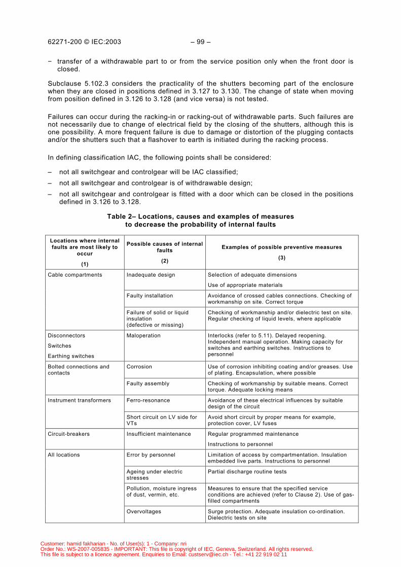
62271-200 © IEC:2003 – 99 –
− transfer of a withdrawable part to or from the service position only when the front door isclosed.
Subclause 5.102.3 considers the practicality of the shutters becoming part of the enclosurewhen they are closed in positions defined in 3.127 to 3.130. The change of state when movingfrom position defined in 3.126 to 3.128 (and vice versa) is not tested.
Failures can occur during the racking-in or racking-out of withdrawable parts. Such failures arenot necessarily due to change of electrical field by the closing of the shutters, although this isone possibility. A more frequent failure is due to damage or distortion of the plugging contactsand/or the shutters such that a flashover to earth is initiated during the racking process.
In defining classification IAC, the following points shall be considered:
– not all switchgear and controlgear will be IAC classified;– not all switchgear and controlgear is of withdrawable design;– not all switchgear and controlgear is fitted with a door which can be closed in the positions
defined in 3.126 to 3.128.
Table 2– Locations, causes and examples of measuresto decrease the probability of internal faults
Locations where internalfaults are most likely to
occur
(1)
Possible causes of internalfaults
(2)
Examples of possible preventive measures
(3)
Inadequate design Selection of adequate dimensions
Use of appropriate materials
Faulty installation Avoidance of crossed cables connections. Checking ofworkmanship on site. Correct torque
Cable compartments
Failure of solid or liquidinsulation(defective or missing)
Checking of workmanship and/or dielectric test on site.Regular checking of liquid levels, where applicable
Disconnectors
Switches
Earthing switches
Maloperation Interlocks (refer to 5.11). Delayed reopening.Independent manual operation. Making capacity forswitches and earthing switches. Instructions topersonnel
Corrosion Use of corrosion inhibiting coating and/or greases. Useof plating. Encapsulation, where possible
Bolted connections andcontacts
Faulty assembly Checking of workmanship by suitable means. Correcttorque. Adequate locking means
Ferro-resonance Avoidance of these electrical influences by suitabledesign of the circuit
Instrument transformers
Short circuit on LV side forVTs
Avoid short circuit by proper means for example,protection cover, LV fuses
Circuit-breakers Insufficient maintenance Regular programmed maintenance
Instructions to personnel
Error by personnel Limitation of access by compartmentation. Insulationembedded live parts. Instructions to personnel
Ageing under electricstresses
Partial discharge routine tests
Pollution, moisture ingressof dust, vermin, etc.
Measures to ensure that the specified serviceconditions are achieved (refer to Clause 2). Use of gas-filled compartments
All locations
Overvoltages Surge protection. Adequate insulation co-ordination.Dielectric tests on site
Customer: hamid fakharian - No. of User(s): 1 - Company: nriOrder No.: WS-2007-005835 - IMPORTANT: This file is copyright of IEC, Geneva, Switzerland. All rights reserved.This file is subject to a licence agreement. Enquiries to Email: [email protected] - Tel.: +41 22 919 02 11
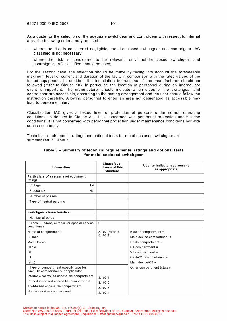
62271-200 © IEC:2003 – 101 –
As a guide for the selection of the adequate switchgear and controlgear with respect to internalarcs, the following criteria may be used:
– where the risk is considered negligible, metal-enclosed switchgear and controlgear IACclassified is not necessary;
– where the risk is considered to be relevant, only metal-enclosed switchgear andcontrolgear, IAC classified should be used;
For the second case, the selection should be made by taking into account the foreseeablemaximum level of current and duration of the fault, in comparison with the rated values of thetested equipment. In addition, the installation instructions of the manufacturer should befollowed (refer to Clause 10). In particular, the location of personnel during an internal arcevent is important. The manufacturer should indicate which sides of the switchgear andcontrolgear are accessible, according to the testing arrangement and the user should follow theinstruction carefully. Allowing personnel to enter an area not designated as accessible maylead to personnel injury.
Classification IAC gives a tested level of protection of persons under normal operatingconditions as defined in Clause A.1. It is concerned with personnel protection under theseconditions; it is not concerned with personnel protection under maintenance conditions nor withservice continuity.
Technical requirements, ratings and optional tests for metal enclosed switchgear aresummarized in Table 3.
Table 3 – Summary of technical requirements, ratings and optional testsfor metal enclosed switchgear
InformationClause/sub-
clause of thisstandard
User to indicate requirementas appropriate
Particulars of system (not equipmentrating)
Voltage kV
Frequency Hz
Number of phases
Type of neutral earthing
Switchgear characteristics Number of poles
Class – indoor, outdoor (or special serviceconditions)
2
Name of compartment:BusbarMain DeviceCableCTVT(etc.)
3.107 (refer to5.103.1)
Type of compartment (specify type foreach HV compartment) if applicable:Interlock-controlled accessible compartmentProcedure-based accessible compartmentTool-based accessible compartmentNon-accessible compartment
3.107.13.107.23.107.33.107.4
Busbar compartment =Main device compartment =Cable compartment =CT compartment =VT compartment =Cable/CT compartment =Main device/CT =Other compartment (state)=
Customer: hamid fakharian - No. of User(s): 1 - Company: nriOrder No.: WS-2007-005835 - IMPORTANT: This file is copyright of IEC, Geneva, Switzerland. All rights reserved.This file is subject to a licence agreement. Enquiries to Email: [email protected] - Tel.: +41 22 919 02 11
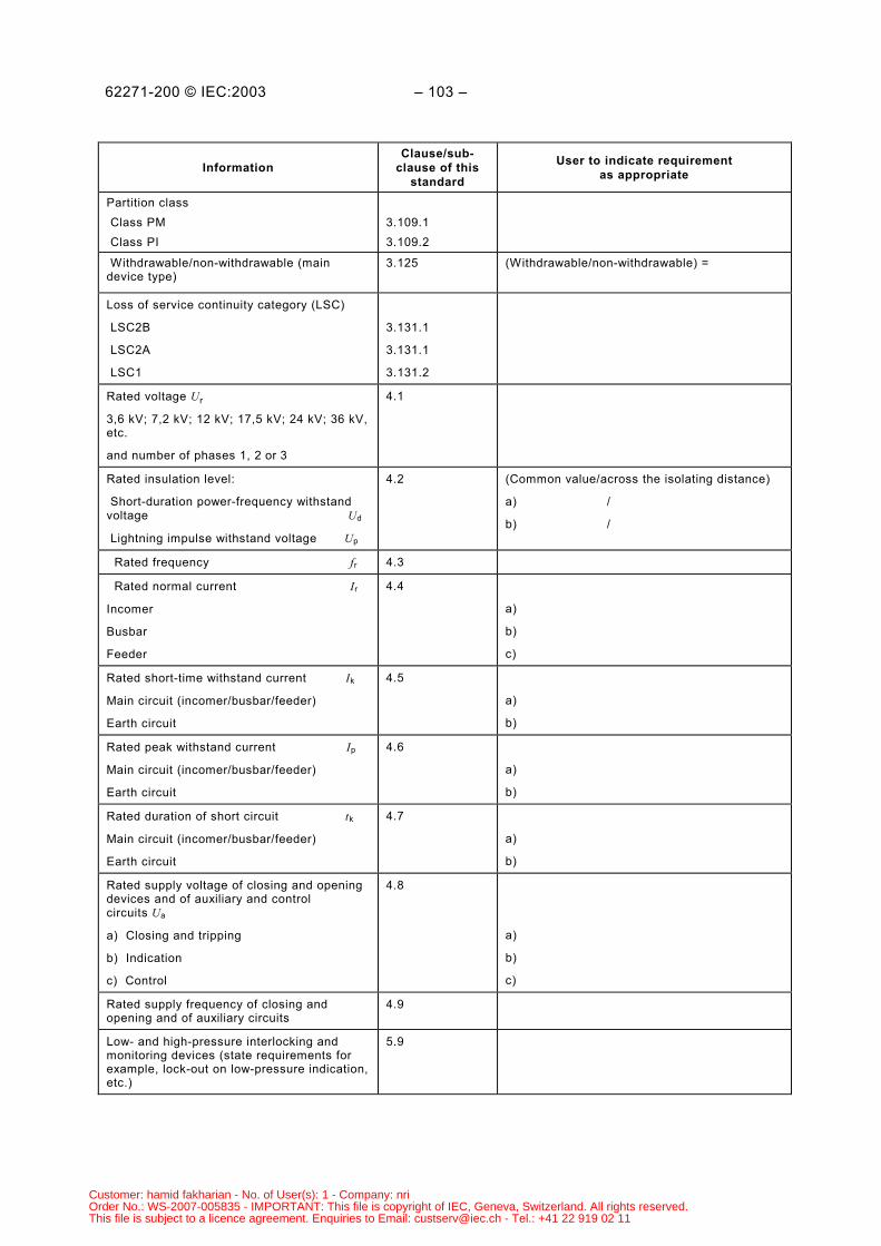
62271-200 © IEC:2003 – 103 –
InformationClause/sub-
clause of thisstandard
User to indicate requirementas appropriate
Partition class Class PM Class PI
3.109.13.109.2
Withdrawable/non-withdrawable (maindevice type)
3.125 (Withdrawable/non-withdrawable) =
Loss of service continuity category (LSC)
LSC2B
LSC2A
LSC1
3.131.1
3.131.1
3.131.2
Rated voltage Ur
3,6 kV; 7,2 kV; 12 kV; 17,5 kV; 24 kV; 36 kV,etc.
and number of phases 1, 2 or 3
4.1
Rated insulation level:
Short-duration power-frequency withstandvoltage Ud
Lightning impulse withstand voltage Up
4.2 (Common value/across the isolating distance)
a) /
b) /
Rated frequency fr 4.3
Rated normal current Ir
Incomer
Busbar
Feeder
4.4
a)
b)
c)
Rated short-time withstand current Ik
Main circuit (incomer/busbar/feeder)
Earth circuit
4.5
a)
b)
Rated peak withstand current Ip
Main circuit (incomer/busbar/feeder)
Earth circuit
4.6
a)
b)
Rated duration of short circuit tk
Main circuit (incomer/busbar/feeder)
Earth circuit
4.7
a)
b)
Rated supply voltage of closing and openingdevices and of auxiliary and controlcircuits Ua
a) Closing and tripping
b) Indication
c) Control
4.8
a)
b)
c)
Rated supply frequency of closing andopening and of auxiliary circuits
4.9
Low- and high-pressure interlocking andmonitoring devices (state requirements forexample, lock-out on low-pressure indication,etc.)
5.9
Customer: hamid fakharian - No. of User(s): 1 - Company: nriOrder No.: WS-2007-005835 - IMPORTANT: This file is copyright of IEC, Geneva, Switzerland. All rights reserved.This file is subject to a licence agreement. Enquiries to Email: [email protected] - Tel.: +41 22 919 02 11
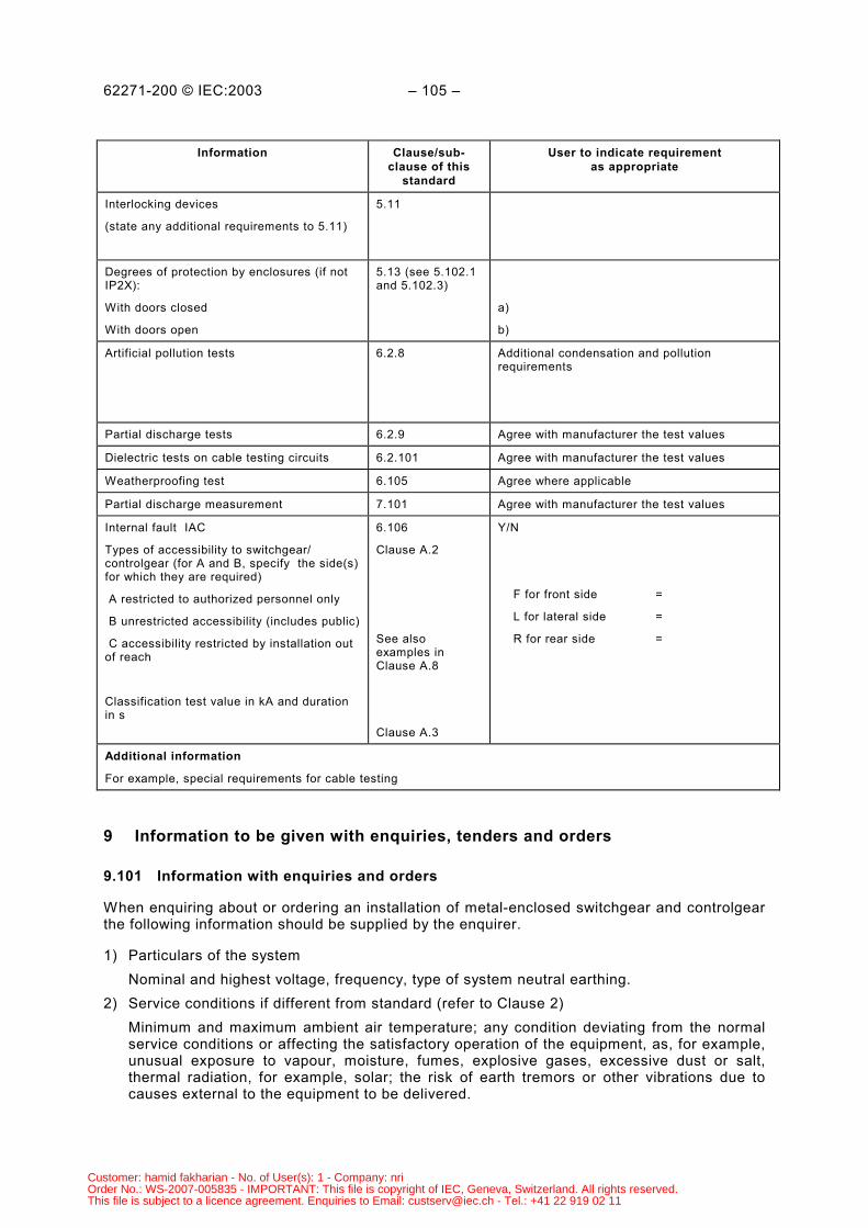
62271-200 © IEC:2003 – 105 –
Information Clause/sub-clause of this
standard
User to indicate requirementas appropriate
Interlocking devices
(state any additional requirements to 5.11)
5.11
Degrees of protection by enclosures (if notIP2X):
With doors closed
With doors open
5.13 (see 5.102.1and 5.102.3)
a)
b)
Artificial pollution tests 6.2.8 Additional condensation and pollutionrequirements
Partial discharge tests 6.2.9 Agree with manufacturer the test values
Dielectric tests on cable testing circuits 6.2.101 Agree with manufacturer the test values
Weatherproofing test 6.105 Agree where applicable
Partial discharge measurement 7.101 Agree with manufacturer the test values
Internal fault IAC
Types of accessibility to switchgear/controlgear (for A and B, specify the side(s)for which they are required)
A restricted to authorized personnel only
B unrestricted accessibility (includes public)
C accessibility restricted by installation outof reach
Classification test value in kA and durationin s
6.106
Clause A.2
See alsoexamples inClause A.8
Clause A.3
Y/N
F for front side =
L for lateral side =
R for rear side =
Additional information
For example, special requirements for cable testing
9 Information to be given with enquiries, tenders and orders
9.101 Information with enquiries and orders
When enquiring about or ordering an installation of metal-enclosed switchgear and controlgearthe following information should be supplied by the enquirer.
1) Particulars of the systemNominal and highest voltage, frequency, type of system neutral earthing.
2) Service conditions if different from standard (refer to Clause 2)Minimum and maximum ambient air temperature; any condition deviating from the normalservice conditions or affecting the satisfactory operation of the equipment, as, for example,unusual exposure to vapour, moisture, fumes, explosive gases, excessive dust or salt,thermal radiation, for example, solar; the risk of earth tremors or other vibrations due tocauses external to the equipment to be delivered.
Customer: hamid fakharian - No. of User(s): 1 - Company: nriOrder No.: WS-2007-005835 - IMPORTANT: This file is copyright of IEC, Geneva, Switzerland. All rights reserved.This file is subject to a licence agreement. Enquiries to Email: [email protected] - Tel.: +41 22 919 02 11
62271-200 © IEC:2003 – 107 –
3) Particulars of the installation and its componentsa) indoor or outdoor installation;b) number of phases;c) number of busbars, as shown in the single line diagram;d) rated voltage;e) rated frequency;f) rated insulation level;g) rated normal currents of busbars and feeder circuits;h) rated short-time withstand current (lk);i) rated duration of short circuit (if different from 1 s);j) rated peak withstand current (if different from 2,5 Ik);k) rated values of components;l) degree of protection for the enclosure and partitions;m) circuit diagrams;n) type of metal-enclosed switchgear and controlgear (LSC1 or LSC2);o) description by name and category of the various compartments, if required;p) class of partitions and shutters (PM or PI);q) classification IAC, if required, with corresponding Ik, Ip, t and FLR, ABC, as applicable
4) Particulars of the operating devices:a) type of operating devices;b) rated supply voltage (if any);c) rated supply frequency (if any);d) rated supply pressure (if any);e) special interlocking requirements.
Beyond these items the enquirer should indicate every condition which might influence the tenderor the order, as, for example, special mounting or erection conditions, the location of the externalhigh-voltage connections or the rules for pressure vessels, requirements for cable testing.
Information should be supplied if special type tests are required.
9.102 Information with tenders
The following information, if applicable, should be given by the manufacturer with descriptivematerial and drawings.
1) Rated values and characteristics as enumerated in item 3 of 9.101.2) Type test certificates or reports on request.3) Constructional features, for example:
a) mass of the heaviest transport unit;b) overall dimensions of the installation;c) arrangement of the external connections;d) facilities for transport and mounting;e) mounting provisions;f) description by name and category of the various compartments;g) accessible sides;
Customer: hamid fakharian - No. of User(s): 1 - Company: nriOrder No.: WS-2007-005835 - IMPORTANT: This file is copyright of IEC, Geneva, Switzerland. All rights reserved.This file is subject to a licence agreement. Enquiries to Email: [email protected] - Tel.: +41 22 919 02 11
62271-200 © IEC:2003 – 109 –
h) instructions for operation and maintenance;i) type of gas-pressure or liquid-pressure system;j) rated filling level and minimum functional level;k) volume of liquid or mass of gas or liquid for the different compartments;l) specification of gas or liquid condition:
4) Particulars of the operating devices:a) types and rated values as enumerated in item 4 of 9.101;b) current or power for operation;c) operating times;d) quantity of free gas for operation.
5) List of recommended spare parts that should be procured by the user.
10 Rules for transport, storage, installation, operation and maintenance
Refer to Clause 10 of IEC 60694.
10.1 Conditions during transport, storage and installation
Refer to 10.1 of IEC 60694.
10.2 Installation
Refer to 10.2 of IEC 60694 with the addition of a new paragraph after the first paragraph of10.2.3.
In the case of classification IAC switchgear and controlgear, guidance on safe installationconditions for the case of an internal arc shall be provided as well. The hazards of the actualinstallation condition shall be assessed with respect to installation conditions of the testspecimen during the internal arcing test (refer to Clause A.3). These conditions are consideredas minimum permissible conditions. Any installation condition less stringent and/or providingmore room is considered to be covered by the test.
However, if the purchaser (user) considers that the risk is not relevant, the switchgear andcontrolgear can be installed without the restrictions indicated by the manufacturer.
10.3 Operation
Refer to 10.3 of IEC 60694
10.4 Maintenance
Refer to 10.4 of IEC 60694 with the following addition:
If temporarily inserted partitions are required, while performing certain maintenanceprocedures, to prevent accidental contact with live parts, then
– the manufacturer shall offer to supply the required partitions or their design;– the manufacturer shall give advice direction as to the maintenance procedure and use of
partitions;– when installed according to the manufacturers directions, the requirements IP-2X
(according to IEC 60529) shall be met;
Customer: hamid fakharian - No. of User(s): 1 - Company: nriOrder No.: WS-2007-005835 - IMPORTANT: This file is copyright of IEC, Geneva, Switzerland. All rights reserved.This file is subject to a licence agreement. Enquiries to Email: [email protected] - Tel.: +41 22 919 02 11
62271-200 © IEC:2003 – 111 –
– such partitions shall meet the requirement of 5.103.3;– the partitions and their supports shall have sufficient mechanical strength to avoid
incidental contact of live parts.NOTE Partitions and supports provided for mechanical protection only are not subject to this standard.
After a short-circuit event in service, the earthing circuit should be examined for potentialdamages and replaced in whole or in part if needed.
11 Safety
Refer to Clause 11 of IEC 60694 with the following addition:
11.101 Procedures
Suitable procedures should be put in place by the user to ensure that a procedure-basedaccessible compartment may be opened only when the part of the main circuit contained in thecompartment being made accessible is dead and earthed, or in the withdrawn position withcorresponding shutters closed. Procedures may be dictated by legislation of the country ofinstallation or by user safety documentation.
11.102 Internal arc aspects
As far as the protection of persons is concerned, the correct performance of the metal-enclosed switchgear and controlgear in case of an internal arc is not only a matter of design ofthe equipment itself, but also of the installation conditions and operating procedure, forinstance, see 8.3.
For indoor installations, arcing due to an internal fault in the metal-enclosed switchgear andcontrolgear may cause overpressure within the switchgear room. This effect is not within thescope of this standard but it should be taken into consideration when designing the installation.
Customer: hamid fakharian - No. of User(s): 1 - Company: nriOrder No.: WS-2007-005835 - IMPORTANT: This file is copyright of IEC, Geneva, Switzerland. All rights reserved.This file is subject to a licence agreement. Enquiries to Email: [email protected] - Tel.: +41 22 919 02 11
62271-200 © IEC:2003 – 113 –
Annex A (normative)
Internal fault −−−−Method for testing the metal-enclosed switchgear and controlgear
under conditions of arcing due to an internal fault
A.1 Introduction
This annex applies to metal-enclosed switchgear and controlgear of classification IAC. Thisclassification is intended to offer a tested level of protection to persons in the vicinity of theequipment in normal operating conditions and with the switchgear and controlgear in normalservice position, in the event of internal arc.
For the purpose of this annex, normal operating conditions means the conditions of metal-enclosed switchgear and controlgear required to carry out operations such as opening orclosing HV switching devices, connecting and disconnecting withdrawable parts, reading ofmeasuring instruments and monitoring equipment, etc. Therefore, if to perform any of suchoperations any cover has to be removed and/or any door has to be opened, the test describedbelow shall be carried out with the cover and/or door removed.
Removing or replacing active components (for example, HV fuses or any other removablecomponent) are not considered to be normal operations, neither those required to carry outmaintenance works.
Internal faults inside metal-enclosed switchgear and controlgear can occur in a number oflocations and can cause various physical phenomena. For example, the arc energy resultingfrom an arc developed in any insulating fluid within the enclosure will cause an internaloverpressure and local overheating which will result in mechanical and thermal stressing of theequipment. Moreover, the materials involved may produce hot decomposition products, eithergaseous or vaporous, which may be discharged to the outside of the enclosure.
The Internal Arc Classification IAC makes allowance for internal overpressure acting oncovers, doors, inspection windows, ventilation openings, etc. It also takes into considerationthe thermal effects of the arc or its roots on the enclosure and of ejected hot gases andglowing particles, but not damage to internal partition and shutters not being accessible innormal operating conditions.NOTE Influences of internal arc between compartments are not yet covered by this standard.
The internal arc test described below is intended to verify the effectiveness of the design inprotecting persons in case of an internal arc. It does not cover all the effects which mayconstitute a hazard, such as the presence of gases with potential toxic characteristics that canbe present after the fault. From this point of view, immediate evacuation and further ventilationof the switchgear room, before re-entering the site, is required.
The hazard of fire propagation after an internal arc to combustible materials or equipmentplaced in the proximity of the metal-enclosed switchgear and controlgear is not covered by thistest.
Customer: hamid fakharian - No. of User(s): 1 - Company: nriOrder No.: WS-2007-005835 - IMPORTANT: This file is copyright of IEC, Geneva, Switzerland. All rights reserved.This file is subject to a licence agreement. Enquiries to Email: [email protected] - Tel.: +41 22 919 02 11
62271-200 © IEC:2003 – 115 –
A.2 Types of accessibility
a) Metal-enclosed switchgear and controlgear, except pole mountedA distinction is made between two types of accessibility to the metal-enclosed switchgearand controlgear which are possible in the site of installation:Accessibility Type A: restricted to authorized personnel only.Accessibility Type B: unrestricted accessibility, including that of the general public.Corresponding to these two types of accessibility, two different test conditions aredescribed in Clause A.3.The metal-enclosed switchgear and controlgear may have different types of accessibility onthe various sides of its enclosure.
For identification purposes of the different sides of the enclosure (refer to Clauses A.7 andA.8) the following code shall be used:
F for Front sideL for Lateral sideR for Rear sideThe Front side shall be clearly stated by the manufacturer
b) Pole-mounted metal-enclosed switchgear and controlgearAccessibility type C: Accessibility restricted by installation out of reachThe minimum admissible height of installation shall be stated by the manufacturer.
A.3 Test arrangements
A.3.1 General
The following points shall be observed.
– The test specimen shall be fully equipped. Mock-ups of internal components are permittedprovided they have the same volume and external material as the original items and they donot affect the main and earthing circuits.
– Each compartment of a functional unit, containing a main circuit component, shall betested. In case of switchgear and controlgear consisting of extensible (modular) stand-alone units, the test specimen shall consist of two units connected together as in service.Testing shall be made at least in all compartments of the end of the switchgear andcontrolgear adjacent to the indicators. However, if there is a substantial difference (to bedeclared by the manufacturer) in strength between the joining sides of adjacent units andthe side forming the end of a switchgear and controlgear, three units shall be used and thetest of the different compartments repeated in the central unit.NOTE A stand-alone unit is an assembly that may contain within a single common enclosure one or morefunctional units in horizontal or vertical arrangement (tier).
– In the case of pole-mounted equipment, the test specimen shall be mounted as if in serviceat the minimum height declared by the manufacturer. If there is a control box and/orelectrical/mechanical linkages to the base of the pole, then these shall be fitted.
– When the test specimen is earthed, it shall be at the point provided.– Tests shall be carried out on compartments not previously subjected to arcing, or, if
subjected, being in a condition which does not affect the result of the test.
Customer: hamid fakharian - No. of User(s): 1 - Company: nriOrder No.: WS-2007-005835 - IMPORTANT: This file is copyright of IEC, Geneva, Switzerland. All rights reserved.This file is subject to a licence agreement. Enquiries to Email: [email protected] - Tel.: +41 22 919 02 11
62271-200 © IEC:2003 – 117 –
– In the case of fluid-filled compartments (other than SF6) the test shall be made with theoriginal fluid at its rated filling conditions (±10 %). It is permitted to replace SF6 with air atthe rated filling conditions (±10 %).NOTE If the test is carried out with air instead of SF6, the pressure rise will be different.
A.3.2 Room simulation
a) Metal-enclosed switchgear and controlgear for indoor applicationThe room shall be represented by a floor, ceiling and two walls perpendicular to each other.Where appropriate simulated cable access ways and/or exhaust ducts shall also be built.CeilingUnless the manufacturer states a larger minimum clearance, the ceiling shall be located ata distance of 600 mm ± 100 mm from the upper part of the test specimen. However, theceiling shall be located at a distance of 2 m from the floor, as a minimum. This provision isapplicable when testing specimens of less than 1,5 m high.The manufacturer may carry out an additional test with lower clearances to the ceiling, inorder to assess criteria for installation conditions.Lateral wallThe lateral wall shall be placed at 100 mm ± 30 mm from the lateral side of the testspecimen. A lower clearance can be chosen provided that it can be demonstrated that anypermanent deformation of the lateral side of the test specimen is not interfered with orlimited by the wall.The manufacturer may carry out an additional test with higher clearances to the lateral wall,in order to assess criteria for installation conditions.Rear wallThe rear wall shall be placed as follows depending on the type of accessibility:Non-accessible rear sideUnless the manufacturer states a larger minimum clearance, the wall shall allow aclearance to the rear of the test specimen of 100 mm ± 30 mm. A lower clearance can bechosen provided that it can be demonstrated that any permanent deformation of the rearside of the test specimen is not interfered with or limited by the wall.This test arrangement is deemed valid for an installation mounted closer to the wall thanthe test arrangement, provided that two additional conditions are met (refer to Clause A.6,Criterion No. 1).If these conditions cannot be demonstrated, or the manufacturer requires directqualification of a wall-mounted design, a specific test without clearance to the rear wallshall be carried out. However, the validity of such a test shall not be extended to any otherinstallation condition.When the test is carried out at any larger clearance to the rear wall, as stated by themanufacturer, this clearance shall be declared as a minimum admissible for the installationinstructions. The instructions shall also include guidance on the obligation to adoptmeasures preventing persons to enter that area.Accessible rear side
The rear wall shall leave a standard clearance of 800 mm (0
100+ mm) from the rear side of
the test specimen.An additional test may be performed with lower clearances, to prove the capability of theswitchgear and controlgear to operate correctly when reduced room is available (forexample, to justify the installation close to a wall, in a no rear-accessibility arrangement).
Customer: hamid fakharian - No. of User(s): 1 - Company: nriOrder No.: WS-2007-005835 - IMPORTANT: This file is copyright of IEC, Geneva, Switzerland. All rights reserved.This file is subject to a licence agreement. Enquiries to Email: [email protected] - Tel.: +41 22 919 02 11
62271-200 © IEC:2003 – 119 –
When the test is carried out at any larger clearance to the rear wall, as stated by themanufacturer, this clearance shall be declared as a minimum admissible for the installationinstructions.Special case, use of exhausting ductsIf the manufacturer claims that the design requires that cable access way and/or any otherexhausting duct need to be used to evacuate gases generated during the internal arc, theirminimum cross-section dimensions, location and output features (flaps or grid, with theircharacteristics) shall be stated by the manufacturer. The test shall be carried out withsimulation of such exhausting ducts. The output end of the exhausting ducts shall be atleast 2 m away from the switchgear and controlgear tested.NOTE The possible effects of hot gases outside of the room containing the switchgear and controlgear are notcovered by this standard.
b) Metal-enclosed switchgear and controlgear for outdoor applicationNeither ceiling nor walls are required if accessibility is stated for all sides (F, L, R).Simulation of cable access ways shall be constructed, if necessary, as indicated above.From the point of view of internal arc, a metal-enclosed switchgear and controlgear passingthe test for indoor application is considered to be valid for outdoor application with the sameaccessibility requirements.In cases where switchgear and controlgear for outdoor application are intended to beplaced under a shelter (for example, for protection against rain) which is less than 1,5 mabove the switchgear and controlgear, a corresponding ceiling should be considered.
A.3.3 Indicators (for assessing the thermal effects of the gases)
A.3.3.1 General
Indicators are pieces of black cotton cloth so arranged that their cut edges do not point towardthe test specimen.
Black cretonne (cotton fabric approximately 150 g/m2) or black cotton-interlining lawn(approximately 40 g/m2) shall be used for indicators, depending on the accessibility condition.
Care shall be taken to see that the vertical indicators can not ignite each other. This is
achieved by fitting them in a frame of steel sheet, with a depth of 2 × 30 mm (30
−mm) (refer to
Figure A.1).
With the horizontal indicators, care shall be taken that glowing particles do not accumulate.This is achieved if the indicators are mounted without frame (refer to Figure A.2).
The indicator dimensions shall be 150 × 150 mm (0
15+ mm)
A.3.3.2 Arrangement of indicators
Indicators shall be placed at each accessible side, on a mounting rack, at distances dependingon the type of accessibility.
Customer: hamid fakharian - No. of User(s): 1 - Company: nriOrder No.: WS-2007-005835 - IMPORTANT: This file is copyright of IEC, Geneva, Switzerland. All rights reserved.This file is subject to a licence agreement. Enquiries to Email: [email protected] - Tel.: +41 22 919 02 11
62271-200 © IEC:2003 – 121 –
The length of the mounting rack shall be larger than the test specimen to take into account thepossibility of hot gases escaping at angles of up to 45º, from the surface under test. Thismeans that the mounting frame on each side – if applicable – shall be 100 mm longer than theunit under test in case of accessibility type B, or 300 mm in case of accessibility type A,provided that the position of the wall in the arrangement of the room simulation does not limitthis extension.
NOTE In all cases the distance from the indicators fitted vertically to the switchgear and controlgear is measuredfrom the surface of the enclosure, disregarding protruding elements (for example, handles, frame of apparatus andso on). If the surface of the switchgear and controlgear is not regular, the indicators should be placed to simulateas realistically as possible the position that a person usually may adopt in front of the equipment, at aboveindicated distance, according to type of accessibility.
a) Accessibility type A (authorized personnel)Black cretonne (cotton fabric approximately 150 g/m2) shall be used for the indicators.Indicators shall be fitted vertically at all accessible sides of the metal-enclosed switchgearand controlgear up to a height of 2 m evenly distributed, arranged in a checkerboardpattern, covering 40-50% of the area (refer to Figures A.3 and A.4).The distance from the indicators to the switchgear and controlgear shall be 300 mm ±15 mm.Indicators shall also be arranged horizontally at a height of 2 m above the floor asdescribed in Figures A.3 and A.4 and covering the whole area between 300 mm and800 mm from the metal-enclosed switchgear and controlgear. When the ceiling is placed ata height of 2 m above the floor (refer to indent a) of A.3.2) no horizontal indicators arerequired. The indicators shall be evenly distributed, arranged in a checkerboard pattern,covering 40-50 % of the area (refer to Figures A.3 and A.4).
b) Accessibility type B (general public)Black cotton-interlining lawn (approximately 40 g/m2) shall be used for indicators.Indicators shall be fitted vertically at all accessible sides for the metal enclosed switchgearand controlgear up to 2 m above the floor. If the actual height of the specimen is lower than1,9 m, vertical indicators shall be fitted up to a height 100 mm higher than the testspecimen.The indicators shall be evenly distributed, arranged in a checkerboard pattern, covering40-50 % of the area (refer to Figures A.3 and A.5).The distance from the indicators to the switchgear and controlgear shall be 100 mm ±5 mm.Indicators shall also be arranged horizontally at a height above the floor, as described inFigure A.5, and covering the whole area between 100 mm and 800 mm from the metal-enclosed switchgear and controlgear. If the test specimen is lower than 2 m, indicatorsshall be placed directly on the top covers as for accessible sides, at a distance of 100 mm ±5 mm (refer to Figure A.6). They shall be evenly distributed, arranged in a checkerboardpattern, covering 40-50 % of the area (refer to Figures A.5 and A.6).
c) Special accessibility conditionBlack cotton-interlining lawn (approximately 40 g/m2) shall be used for indicators.Where normal operation requires persons to stand or walk upon the equipment, horizontalindicators shall be placed above upper accessible surface, as described in Figure A.6,whatever the height of the switchgear and controlgear.
d) Accessibility type C – Pole-mounted equipmentBlack cotton-interlining lawn (approximately 40 g/m2) shall be used for indicators.Indicators shall be arranged horizontally, at a height of 2 m covering the whole area of a3 × 3 m2 square frame centred about the pole. They shall be evenly distributed, arranged ina checkerboard pattern, covering 40 % to 50 % of the area (refer to Figure A.7).
Customer: hamid fakharian - No. of User(s): 1 - Company: nriOrder No.: WS-2007-005835 - IMPORTANT: This file is copyright of IEC, Geneva, Switzerland. All rights reserved.This file is subject to a licence agreement. Enquiries to Email: [email protected] - Tel.: +41 22 919 02 11
62271-200 © IEC:2003 – 123 –
A.4 Current and voltage applied
A.4.1 General
The tests on metal-enclosed switchgear and controlgear shall be carried out three-phase (forthree-phase systems). The short-circuit current applied during the test corresponds to the ratedshort-time withstand current. It may be lower, if specified by the manufacturer.
A test performed at a given voltage, current and duration is generally valid for all lower valuesof current, voltage and duration.
NOTE Lower current level may influence the behaviour of the pressure relief devices and the burn throughperformance. For short-circuit current levels lower than tested, care should be taken in the interpretation of theresults.
A.4.2 Voltage
The applied voltage of the test circuit should be equal to the rated voltage of themetal-enclosed switchgear and controlgear. If the capability of the test plant does not permitthis, a lower voltage may be chosen provided the following conditions are met for the durationof the test:
a) the true r.m.s. current value as computed by a digital recording device complies withcurrent requirements of A.4.3;
b) the arc is not extinguished prematurely in any of the phases in which it has been initiated.
A.4.3 Current
A.4.3.1 AC component
The short-circuit current for which the metal-enclosed switchgear and controlgear is specified
with respect to arcing shall be set within a 05+ % tolerance. If the applied voltage is equal to the
rated voltage, this tolerance applies to the prospective current.
The current should remain constant. If the capability of the test plant does not permit this, thetest shall be extended until the integral of the a.c. component of the current equals the value
specified within a tolerance of (0
10+ %). In this case, the current shall be equal to the specified
value at least during the first three half-cycles and shall not be less than 50 % of the specifiedvalue at the end of the test.
A.4.3.2 Peak current
The instant of closing shall be chosen so that the prospective value of the peak current, with a
tolerance of (05+ %), flowing in one of the outer phases is 2,5 times (for frequencies up to
50 Hz) or 2,6 times (for 60 Hz) the r.m.s. value of the a.c. component defined in A.4.3.1, andso that a major loop also occurs in the other outer phase. If the voltage is lower than the ratedvoltage, the peak value of the short-circuit current for the metal-enclosed switchgear andcontrolgear under test shall not drop below 90 % of the rated peak value.
NOTE For other, higher, d.c. time constants of the feeding network, a uniform value of 2,7 times the r.m.s. valueof the a.c. component should be used as a rated value for both 50 Hz and 60 Hz applications.
Customer: hamid fakharian - No. of User(s): 1 - Company: nriOrder No.: WS-2007-005835 - IMPORTANT: This file is copyright of IEC, Geneva, Switzerland. All rights reserved.This file is subject to a licence agreement. Enquiries to Email: [email protected] - Tel.: +41 22 919 02 11
62271-200 © IEC:2003 – 125 –
In case of two-phase initiating of the arc the instant of closing shall be chosen to provide themaximum possible d.c. component.
A.4.4 Frequency
At a rated frequency of 50 Hz or 60 Hz, the frequency at the beginning of the test shall bebetween 48 Hz and 62 Hz. At other frequencies it shall not deviate from the rated value bymore than ±10 %.
Where the operation of fast-acting protective devices is dependent on the frequency, the testshall be performed with the rated frequency of these devices ±10 %.
A.4.5 Duration of the test
The test duration shall be stated by the manufacturer. Standard recommended values are 1 s,0,5 s and 0,1 s.
NOTE It is in general not possible to calculate the permissible arc duration for a current which differs from thatused in the test. The maximum pressure during the test will generally not decrease with a shorter arcing time andthere is no universal rule according to which the permissible arc duration may be increased with a lower testcurrent.
A.5 Test procedure
A.5.1 Supply circuit
If applicable, the supply circuit shall be three-phase, except for tests on switchgear andcontrolgear with segregated phases, if no mutual influence between the segregated phasecompartments is likely. The neutral point of the supply circuit may be either isolated or earthedthrough an impedance, in such a way that the maximum earth current is less than 100 A. In thissituation, the arrangement covers all situations of neutral treatment.
NOTE 1 Internal arc faults with a directly grounded neutral are less severe.
When the test is made on part of the switchgear and controlgear where phases are segregated,the supply circuit shall be single-phase, one of the terminals earthed. The test current shall beequal to the three-phase value stated in A.4.3.1.
Care shall be taken in order that the connections do not alter the test conditions.
Feeding direction shall be as follows:
– for a cable compartment: supply from the busbar, through the main switching device;– for a busbar compartment: the supply connections shall not introduce any opening in the
compartment under test. Supply shall be made through one barrier, if barriers are fitted tocreate separated busbar compartments between functional units, or through the mainswitching device located at one end of the switchgear and controlgear, if the busbarcompartment is common for the whole switchgear and controlgear;NOTE 2 In case of non-symmetrical designs of busbar compartment, the most onerous internal arc initiationshould be considered, with respect to arc energy and burn through.
– for the main switching device compartment: supply from the busbar, with the device inclosed position;
– for a compartment with several main circuit components inside: supply through oneavailable set of incoming bushings, with all switching devices in closed position, except forearthing switches, if any, which shall be in open position.
Customer: hamid fakharian - No. of User(s): 1 - Company: nriOrder No.: WS-2007-005835 - IMPORTANT: This file is copyright of IEC, Geneva, Switzerland. All rights reserved.This file is subject to a licence agreement. Enquiries to Email: [email protected] - Tel.: +41 22 919 02 11
62271-200 © IEC:2003 – 127 –
A.5.2 Arc initiation
The arc shall be initiated between all the phases by means of a metal wire of about 0,5 mm indiameter or, in the case of segregated phase conductors, between one phase and earth.
The point of initiation shall be located at the furthest accessible point from the supply, withinthe compartment under test.
In functional units where the live parts are covered by solid insulating material, the arc shall beinitiated between two adjacent phases with a current value of 87 % of the rated current or, inthe case of segregated phase conductors, between one phase and earth at the followinglocations:
a) at gaps or joining surfaces between the insulation of insulation-embedded parts;b) by perforation at insulated joints made on site when prefabricated insulating parts are not
used.
Except for case b), solid insulation shall not be perforated. The supply circuit shall be three-phase to allow the fault to become three-phase (if applicable).
A.5.2.1 Cable compartments with plug in or site-made solid insulation connections
For cable compartments in which connections are always made with plug-in connectors,screened or not, or site-made solid insulation, the two phases under test shall be fitted withplugs without insulation. The third phase shall be provided with a plug-in connector as can beused in service, able to be energized.
NOTE Experience shows that the fault generally does not evolve towards a three-phase fault; therefore, the choiceof the fitting for the third phase is not critical.
In all these cases of phase-to-phase fault, the test current shall be the phase-to-phase faultcurrent of the three-phase supply circuit defined according to A.4.3. That means the actualcurrent value, unless the fault evolves towards a three-phase fault, is reduced to approximately0,87 % the specified internal arc withstand current.
In solidly earthed networks (non-floating neutral), or in networks with earth-fault protection, thesingle phase-to-earth short-circuit current, which is generally lower than the possible two-phasefault current, will be switched off rapidly. For switchgear and controlgear, only intended for thisrestricted use, it is acceptable to test accordingly, instead of the two-phase test describedabove. The arc will then be ignited as single-phase to ground, provided that the other phasesare energized to allow the arc to become three-phase. As the specified internal arc withstandcurrent, the tested single-phase value applies.
A.6 Acceptance criteria
Metal-enclosed switchgear and controlgear is qualified as classification IAC (according to therelevant accessibility type) if the following criteria are met.
Criterion No. 1
Correctly secured doors and covers do not open. Deformations are accepted, provided that nopart comes as far as the position of the indicators or the walls (whichever is the closest) inevery side. The switchgear and controlgear do not need to comply with its IP code after thetest.
Customer: hamid fakharian - No. of User(s): 1 - Company: nriOrder No.: WS-2007-005835 - IMPORTANT: This file is copyright of IEC, Geneva, Switzerland. All rights reserved.This file is subject to a licence agreement. Enquiries to Email: [email protected] - Tel.: +41 22 919 02 11
62271-200 © IEC:2003 – 129 –
To extend the acceptance criterion to an installation mounted closer to the wall than tested(refer to item a) of A.3.2), two additional conditions shall be met:
– the permanent deformation is less than the intended distance to the wall;– exhausting gases are not directed to the wall.
Criterion No. 2– No fragmentation of the enclosure occurs within the time specified for the test.– Projections of small parts, up to an individual mass of 60 g, are accepted.
Criterion No. 3
Arcing does not cause holes in the accessible sides up to a height of 2 m.
Criterion No. 4
Indicators do not ignite due to the effect of hot gases.
Should they start to burn during the test, the assessment criterion may be regarded as havingbeen met, if proof is established of the fact that the ignition was caused by glowing particlesrather than hot gases. Pictures taken by high-speed cameras, video or any other suitablemeans can be used by the test laboratory to establish evidence.
Indicators ignited as a result of paint or stickers burning are also excluded.
Criterion No. 5
The enclosure remains connected to its earthing point. Visual inspection is generally sufficientto assess compliance. In case of doubt, the continuity of the earthing connection shall bechecked (refer to 6.6, point b)).
A.7 Test report
The following information shall be given in the test report.
– Rating and description of the test unit with a drawing showing the main dimensions, detailsrelevant to the mechanical strength, the arrangement of the pressure relief flaps and themethod of fixing the metal-enclosed switchgear and controlgear to the floor and/or to thewalls. For pole-mounted metal-enclosed switchgear and controlgear, the polecharacteristics with the method of fixing to the pole shall be given.
– Arrangement of the test connections.– Point and method of initiation of the internal fault.– Drawings of test arrangement (room simulation, test specimen and mounting frame of
indicators) with respect to the type of accessibility (A, B or C), side (F, L or R) andinstallation conditions.
– Applied voltage and frequency. – For the prospective or test current:
a) r.m.s. value of the a.c. component during the first three half-cycles; b) highest peak value; c) average value of the a.c. component over the actual duration of the test; d) test duration.
Customer: hamid fakharian - No. of User(s): 1 - Company: nriOrder No.: WS-2007-005835 - IMPORTANT: This file is copyright of IEC, Geneva, Switzerland. All rights reserved.This file is subject to a licence agreement. Enquiries to Email: [email protected] - Tel.: +41 22 919 02 11
62271-200 © IEC:2003 – 131 –
– Oscillogram(s) showing currents and voltages.– Assessment of the test results, including a record of the observations in accordance with
Clause A.6.– Photographs of the object under test, before and after test.– Other relevant remarks.
A.8 Designation of IAC classification
In the case where classification IAC is proven by the tests, according to 6.106, the metal-enclosed switchgear and controlgear will be designated as follows.
– General: classification IAC (initials for Internal Arc Classified)– Accessibility: A, B or C (according to Clause A.2)– Test values: test current in kiloamperes (kA), and duration in seconds (s).
This designation shall be included in the nameplate (refer to 5.10)
Example 1: A metal-enclosed switchgear and controlgear tested for a fault current (r.m.s.) of12,5 kA, for 0,5 s, intended to be installed in a site of public accessibility and tested withindicators placed in front, lateral and rear side, is designated as follows:
Classification IAC BFLRInternal arc 12,5 kA 0,5 s
Example 2: A metal-enclosed switchgear and controlgear tested for a fault current (r.m.s.) of16 kA, for 1 s, intended to be installed in the following conditions:
front: public accessibilityrear: restricted to operatorslateral: not accessible
is designated as follows:
classification IAC BF-ARinternal arc 16 kA 1 s.
Customer: hamid fakharian - No. of User(s): 1 - Company: nriOrder No.: WS-2007-005835 - IMPORTANT: This file is copyright of IEC, Geneva, Switzerland. All rights reserved.This file is subject to a licence agreement. Enquiries to Email: [email protected] - Tel.: +41 22 919 02 11
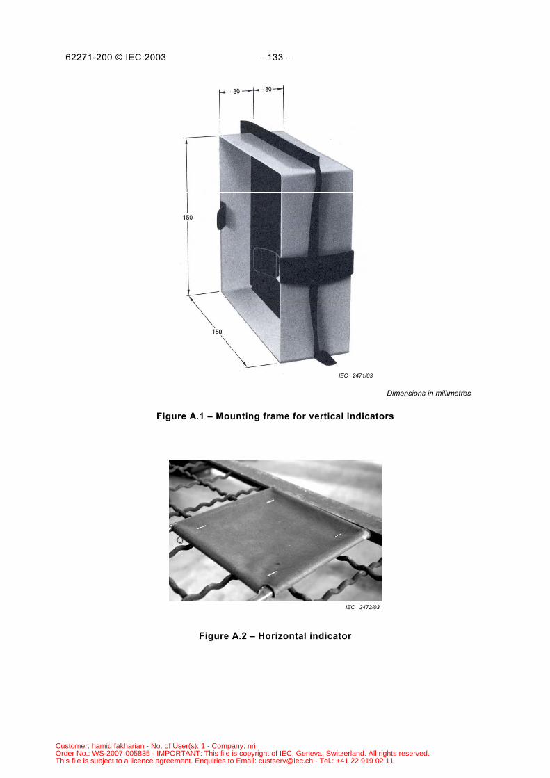
62271-200 © IEC:2003 – 133 –
IEC 2471/03
Dimensions in millimetres
Figure A.1 – Mounting frame for vertical indicators
IEC 2472/03
Figure A.2 – Horizontal indicator
Customer: hamid fakharian - No. of User(s): 1 - Company: nriOrder No.: WS-2007-005835 - IMPORTANT: This file is copyright of IEC, Geneva, Switzerland. All rights reserved.This file is subject to a licence agreement. Enquiries to Email: [email protected] - Tel.: +41 22 919 02 11
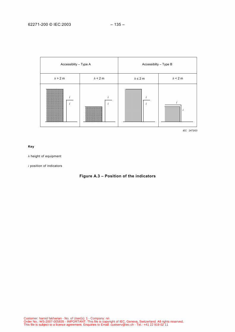
62271-200 © IEC:2003 – 135 –
Accessiblity – Type A Accessiblity – Type B
h > 2 m h < 2 m h ≤ 2 m h < 2 m
i
i
i
i
i
i i
i
IEC 2473/03
Key
h height of equipment
i position of indicators
Figure A.3 – Position of the indicators
Customer: hamid fakharian - No. of User(s): 1 - Company: nriOrder No.: WS-2007-005835 - IMPORTANT: This file is copyright of IEC, Geneva, Switzerland. All rights reserved.This file is subject to a licence agreement. Enquiries to Email: [email protected] - Tel.: +41 22 919 02 11
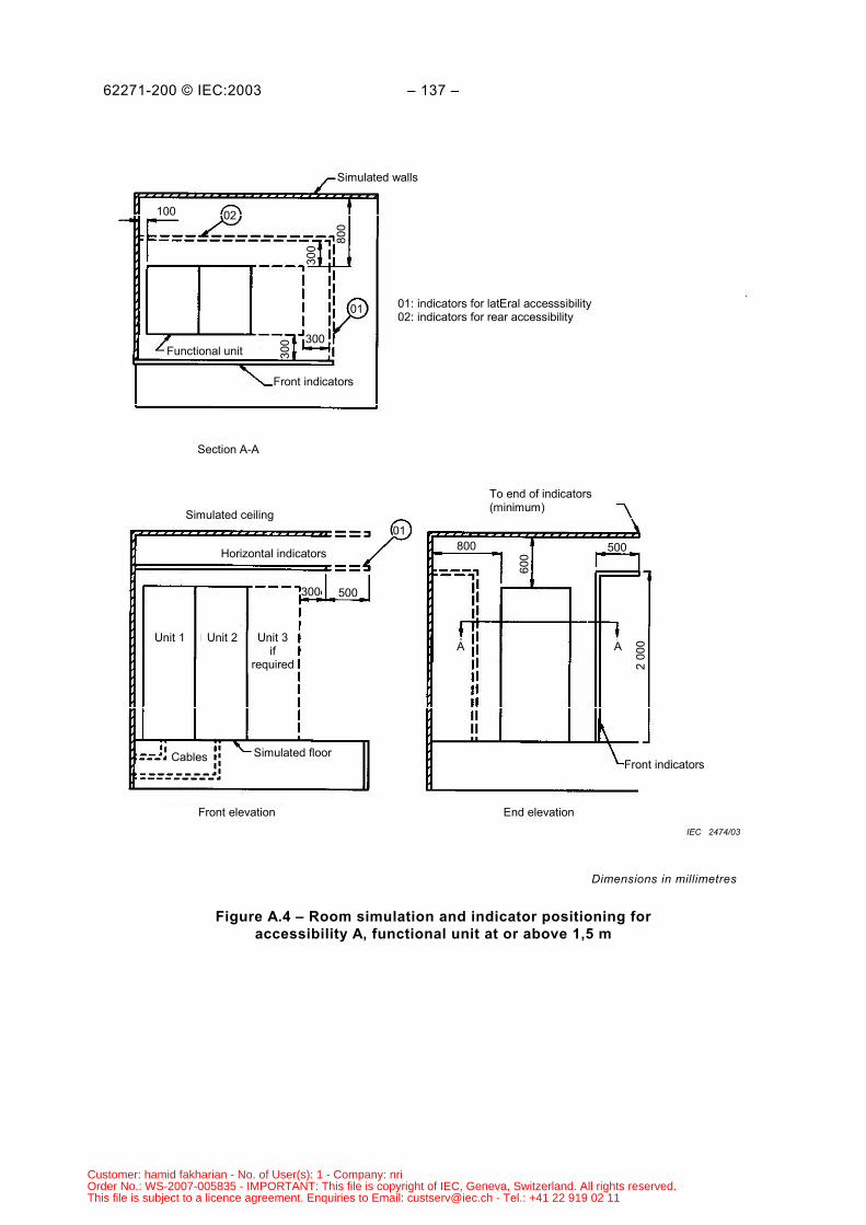
62271-200 © IEC:2003 – 137 –
Simulated walls
100 02
01
300
300
300
800
Front indicators
Functional unit
Section A-A
01: indicators for latEral accesssibility02: indicators for rear accessibility
Simulated ceiling
Horizontal indicators
300 500
800 500
600
2 00
0
Front indicators
A AUnit 1 Unit 2 Unit 3
ifrequired
To end of indicators(minimum)
Cables Simulated floor
Front elevation End elevation
01
IEC 2474/03
Dimensions in millimetres
Figure A.4 – Room simulation and indicator positioning foraccessibility A, functional unit at or above 1,5 m
Customer: hamid fakharian - No. of User(s): 1 - Company: nriOrder No.: WS-2007-005835 - IMPORTANT: This file is copyright of IEC, Geneva, Switzerland. All rights reserved.This file is subject to a licence agreement. Enquiries to Email: [email protected] - Tel.: +41 22 919 02 11
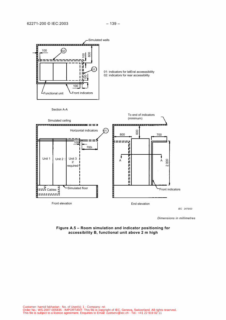
62271-200 © IEC:2003 – 139 –
Simulated walls
100 02
01
10010
010
0
800
Front indicatorsFunctional unit
Section A-A
01: indicators for latEral accesssibility02: indicators for rear accessibility
Simulated ceiling
Horizontal indicators
100700
800 700600
2 00
0
Front indicators
A AUnit 1 Unit 2 Unit 3if
required
To end of indicators(minimum)
Cables Simulated floor
Front elevation End elevation
01
IEC 2475/03
Dimensions in millimetres
Figure A.5 – Room simulation and indicator positioning foraccessibility B, functional unit above 2 m high
Customer: hamid fakharian - No. of User(s): 1 - Company: nriOrder No.: WS-2007-005835 - IMPORTANT: This file is copyright of IEC, Geneva, Switzerland. All rights reserved.This file is subject to a licence agreement. Enquiries to Email: [email protected] - Tel.: +41 22 919 02 11
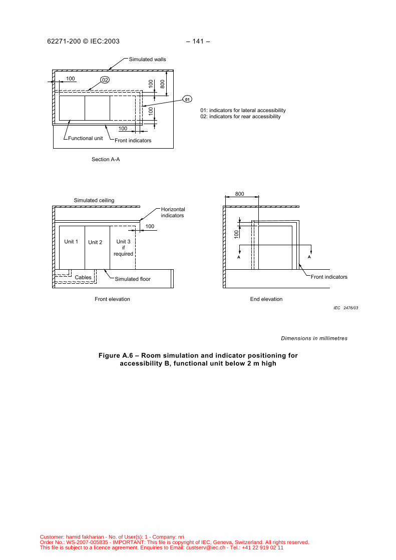
62271-200 © IEC:2003 – 141 –
01
Functional unit Front indicators
02
Simulated walls
01: indicators for lateral accessibility02: indicators for rear accessibility
Simulated ceilingHorizontalindicators
Unit 1 Unit 2 Unit 3if
required
Cables Simulated floor
Section A-A
Front elevation
Front indicators
A A
End elevation
100
800
100
100
100
100
800
100
IEC 2476/03
Dimensions in millimetres
Figure A.6 – Room simulation and indicator positioning foraccessibility B, functional unit below 2 m high
Customer: hamid fakharian - No. of User(s): 1 - Company: nriOrder No.: WS-2007-005835 - IMPORTANT: This file is copyright of IEC, Geneva, Switzerland. All rights reserved.This file is subject to a licence agreement. Enquiries to Email: [email protected] - Tel.: +41 22 919 02 11
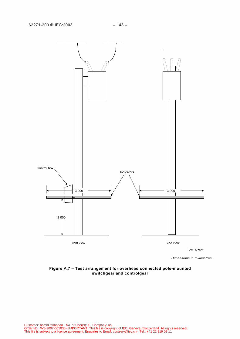
62271-200 © IEC:2003 – 143 –
Indicators
3 000
Front view Side view
2 000
Control box
3 000
IEC 2477/03
Dimensions in millimetres
Figure A.7 – Test arrangement for overhead connected pole-mountedswitchgear and controlgear
Customer: hamid fakharian - No. of User(s): 1 - Company: nriOrder No.: WS-2007-005835 - IMPORTANT: This file is copyright of IEC, Geneva, Switzerland. All rights reserved.This file is subject to a licence agreement. Enquiries to Email: [email protected] - Tel.: +41 22 919 02 11
62271-200 © IEC:2003 – 145 –
Annex B (normative)
Partial discharge measurement
B.1 General
The measurement of partial discharges is a suitable means of detecting certain defects in theequipment under test and is a useful complement to the dielectric tests. Experience shows thatpartial discharges may, in particular arrangements, lead to a progressive degradation in thedielectric strength of the insulation, especially of solid insulation, and fluid-filled compartments.
On the other hand, it is not yet possible to establish a reliable relationship between the resultsof partial discharge measurements and the life expectancy of the equipment owing to thecomplexity of the insulation systems used in metal-enclosed switchgear and controlgear.
B.2 Application
The measurement of partial discharges may be appropriate for metal-enclosed switchgear andcontrolgear if organic insulating materials are used therein and is recommended for fluid-filledcompartments.
Because of the design variations, a general specification for the test object cannot be given. Ingeneral, the test object should consist of assemblies or subassemblies with dielectric stresseswhich are identical to those which would occur in the complete assembly of the equipment.
NOTE 1 Test objects consisting of a complete assembly are to be preferred. In the case of integrated switchgearand controlgear design, especially where various live parts and connections are embedded in solid insulation, testsare necessarily carried out on a complete assembly.
NOTE 2 In the case of designs consisting of a combination of conventional components (for instance, instrumenttransformers, bushings), which can be tested separately in accordance with their relevant standards, the purpose ofthis partial discharge test is to check the arrangement of the components in the assembly.
For technical and economic reasons, it is recommended that the partial discharge tests beperformed on the same assemblies or subassemblies as are used for the mandatory dielectrictests.
NOTE 3 This test may be carried out on assemblies or subassemblies. Care has to be taken that external partialdischarges do not affect the measurement.
Criteria to be considered in deciding on the necessity for a partial discharge test are, forinstance:
a) practical experience in service including the results of such testing over a period ofproduction;
b) the value of the electric field strength at the most highly stressed area of the solid insulation;c) the type of insulating material used in the equipment as part of the major insulation.
Customer: hamid fakharian - No. of User(s): 1 - Company: nriOrder No.: WS-2007-005835 - IMPORTANT: This file is copyright of IEC, Geneva, Switzerland. All rights reserved.This file is subject to a licence agreement. Enquiries to Email: [email protected] - Tel.: +41 22 919 02 11
62271-200 © IEC:2003 – 147 –
B.3 Test circuits and measuring instruments
If partial discharge tests are performed, they shall be in accordance with IEC 60270.
Three-phase equipment is either tested in a single-phase test circuit or in a three-phase testcircuit (refer to Table B.1).
a) Single-phase test circuitProcedure A
To be used as a general method for equipment designed for use in systems with orwithout solidly earthed neutral.For measuring the partial discharge quantities, each phase shall be connected to the testvoltage source successively, the other two phases and all the parts earthed in servicebeing earthed.
Procedure BTo be used only for equipment exclusively designed for use in systems with solidlyearthed neutral.For measuring the partial discharge quantities, two test arrangements shall be used.At first, measurements shall be made at a test voltage of 1,1 Ur (Ur is the rated voltage).Each phase shall be connected to the test voltage source successively, the other twophases being earthed. It is necessary to insulate or to remove all the metallic partsnormally earthed in service.
An additional measurement shall be made at a reduced test voltage of 1,1 3rU duringwhich the parts being earthed in service are earthed and the three phases connected tothe test voltage source are bridged.
b) Three-phase test circuitWhen suitable test facilities are available, the partial discharge tests may be carried out ina three-phase arrangement.In this case, it is recommended to use three coupling capacitors connected as shown inFigure B.1. One discharge detector can be used which is connected successively to thethree measuring impedances.For calibration of the detector on one measuring position of the three-phase arrangement,short-duration current pulses of known charge are injected between each of the phasestaken in turn on the one hand, and the earth and the other two phases, on the other hand.The calibration giving the lowest deflection is used for the determination of the dischargequantity.In the case of equipment designed for use in systems without solidly earthed neutral, anadditional test shall be made (as type test only). For this test each phase of the test objectand the corresponding phase of the voltage source shall be earthed successively (refer toFigure B.2).
B.4 Test procedure
The applied power-frequency voltage is raised to a pre-stress value of at least 1,3 Ur or1,3 3rU in accordance with the test circuit (refer to Table B.1) and maintained at this valuefor at least 10 s2. Partial discharges occurring during this period shall be disregarded.
___________2 Alternatively, the partial discharge test may be performed while decreasing the voltage after the power-
frequency voltage tests.
Customer: hamid fakharian - No. of User(s): 1 - Company: nriOrder No.: WS-2007-005835 - IMPORTANT: This file is copyright of IEC, Geneva, Switzerland. All rights reserved.This file is subject to a licence agreement. Enquiries to Email: [email protected] - Tel.: +41 22 919 02 11
62271-200 © IEC:2003 – 149 –
The voltage is then decreased without interruption to 1,1 Ur or 1,1 3rU in accordance withthe test circuit and the partial discharge quantity is measured at this test voltage (refer to TableB.1).
As far as possible with respect to the actual background noise level, the partial dischargeinception and the partial discharge extinction voltages should be recorded for additionalinformation.
In general, tests on assemblies or subassemblies should be made with the switching devices inthe closed position. In the case of disconnectors where deterioration of the insulation betweenthe open contacts by partial discharges is conceivable, additional partial dischargemeasurements should be made with the disconnector in the open position.
On fluid-filled equipment the tests shall be carried out at the minimum functional level or therated filling level, whichever is most onerous. For routine tests the rated filling level shall beapplied.
B.5 Maximum permissible partial discharge quantity
The recommended partial discharge quantity is apparent charge that is expressed usually inpicocoulombs (pC).
The maximum permissible partial discharge quantity at 1,1 Ur and/or 1,1 3rU shall beagreed between the manufacturer and the user.
For solid insulation, acceptable limits seem to be 10 pC at 1,1 Ur phase-to-phase voltage (at1,1 3rU phase-to-earth voltage) and for systems with no solidly earthed neutral also 100 pCat 1.1 Ur phase-to-earth voltage.
NOTE Limit values of the partial discharge quantity will not be specified until further substantiated information isavailable. Components of metal-enclosed switchgear and controlgear may use one or more different technologies(for example, solid, gas or fluid insulation) each of which has different requirements. It would therefore be verydifficult and controversial to prescribe maximum acceptable levels for general application to the complete, orpartial, assembly. For the time being, these values are left to the responsibility of the manufacturer or, in the caseof acceptance tests, are subject to agreement between the manufacturer and the user.
Customer: hamid fakharian - No. of User(s): 1 - Company: nriOrder No.: WS-2007-005835 - IMPORTANT: This file is copyright of IEC, Geneva, Switzerland. All rights reserved.This file is subject to a licence agreement. Enquiries to Email: [email protected] - Tel.: +41 22 919 02 11
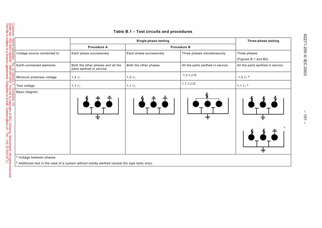
62271-200 © IE
C:2003 – 151 –
Table B.1 – Test circuits and procedures
Single-phase testing Three-phase testing
Procedure A Procedure B
Voltage source connected to Each phase successively Each phase successively Three phases simultaneously Three phases
(Figures B.1 and B2)
Earth-connected elements Both the other phases and all theparts earthed in service
Both the other phases All the parts earthed in service All the parts earthed in service
Minimum prestress voltage 1,3 Ur 1,3 Ur 1,3 Ur/√3
1,3 Ur a
Test voltage 1,1 Ur 1,1 Ur1,1 Ur/√3
1,1 Ur a
Basic diagram
a Voltage between phases.b Additional test in the case of a system without solidly earthed neutral (for type tests only).
b
Custom
er: hamid fakharian - N
o. of User(s): 1 - C
ompany: nri
Order N
o.: WS
-2007-005835 - IMP
OR
TA
NT
: This file is copyright of IE
C, G
eneva, Sw
itzerland. All rights reserved.
This file is subject to a licence agreem
ent. Enquiries to E
mail: custserv@
iec.ch - Tel.: +
41 22 919 02 11
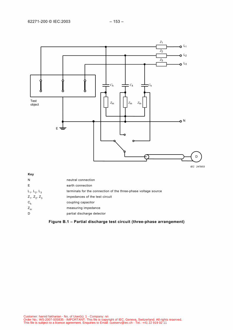
62271-200 © IEC:2003 – 153 –
D
Zm
E
Testobject Zm Zm
Ck Ck Ck
Z1
Z2
Z3
L1
L3
L2
N
IEC 2478/03
Key
N neutral connection
E earth connection
L1, L2, L3 terminals for the connection of the three-phase voltage source
Z1, Z2, Z3 impedances of the test circuit
Ck coupling capacitor
Zm measuring impedance
D partial discharge detector
Figure B.1 – Partial discharge test circuit (three-phase arrangement)
Customer: hamid fakharian - No. of User(s): 1 - Company: nriOrder No.: WS-2007-005835 - IMPORTANT: This file is copyright of IEC, Geneva, Switzerland. All rights reserved.This file is subject to a licence agreement. Enquiries to Email: [email protected] - Tel.: +41 22 919 02 11
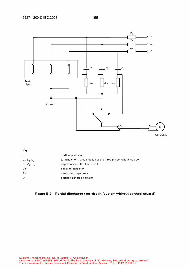
62271-200 © IEC:2003 – 155 –
D
Zm
E
Testobject Zm Zm
Ck Ck Ck
Z1
Z2
Z3
L1
L3
L2
IEC 2479/03
Key
E earth connection
L1, L2, L3 terminals for the connection of the three-phase voltage source
Z1, Z2, Z3 impedances of the test circuit
Ck coupling capacitor
Zm measuring impedance
D partial-discharge detector
Figure B.2 – Partial-discharge test circuit (system without earthed neutral)
Customer: hamid fakharian - No. of User(s): 1 - Company: nriOrder No.: WS-2007-005835 - IMPORTANT: This file is copyright of IEC, Geneva, Switzerland. All rights reserved.This file is subject to a licence agreement. Enquiries to Email: [email protected] - Tel.: +41 22 919 02 11
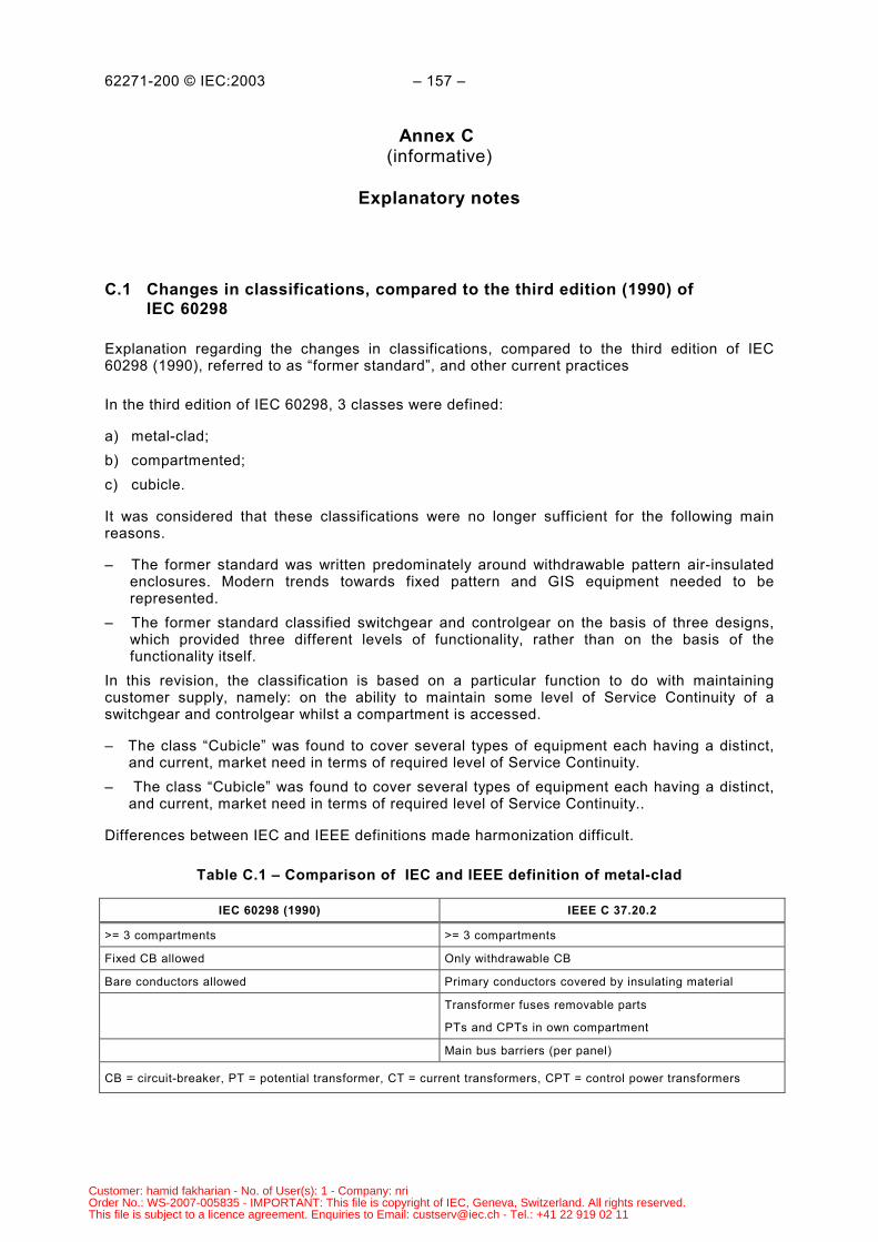
62271-200 © IEC:2003 – 157 –
Annex C (informative)
Explanatory notes
C.1 Changes in classifications, compared to the third edition (1990) ofIEC 60298
Explanation regarding the changes in classifications, compared to the third edition of IEC60298 (1990), referred to as “former standard”, and other current practices
In the third edition of IEC 60298, 3 classes were defined:
a) metal-clad;b) compartmented;c) cubicle.
It was considered that these classifications were no longer sufficient for the following mainreasons.
– The former standard was written predominately around withdrawable pattern air-insulatedenclosures. Modern trends towards fixed pattern and GIS equipment needed to berepresented.
– The former standard classified switchgear and controlgear on the basis of three designs,which provided three different levels of functionality, rather than on the basis of thefunctionality itself.
In this revision, the classification is based on a particular function to do with maintainingcustomer supply, namely: on the ability to maintain some level of Service Continuity of aswitchgear and controlgear whilst a compartment is accessed.
– The class “Cubicle” was found to cover several types of equipment each having a distinct, and current, market need in terms of required level of Service Continuity.– The class “Cubicle” was found to cover several types of equipment each having a distinct, and current, market need in terms of required level of Service Continuity..
Differences between IEC and IEEE definitions made harmonization difficult.
Table C.1 – Comparison of IEC and IEEE definition of metal-clad
IEC 60298 (1990) IEEE C 37.20.2
>= 3 compartments >= 3 compartments
Fixed CB allowed Only withdrawable CB
Bare conductors allowed Primary conductors covered by insulating material
Transformer fuses removable parts
PTs and CPTs in own compartment
Main bus barriers (per panel)
CB = circuit-breaker, PT = potential transformer, CT = current transformers, CPT = control power transformers
Customer: hamid fakharian - No. of User(s): 1 - Company: nriOrder No.: WS-2007-005835 - IMPORTANT: This file is copyright of IEC, Geneva, Switzerland. All rights reserved.This file is subject to a licence agreement. Enquiries to Email: [email protected] - Tel.: +41 22 919 02 11
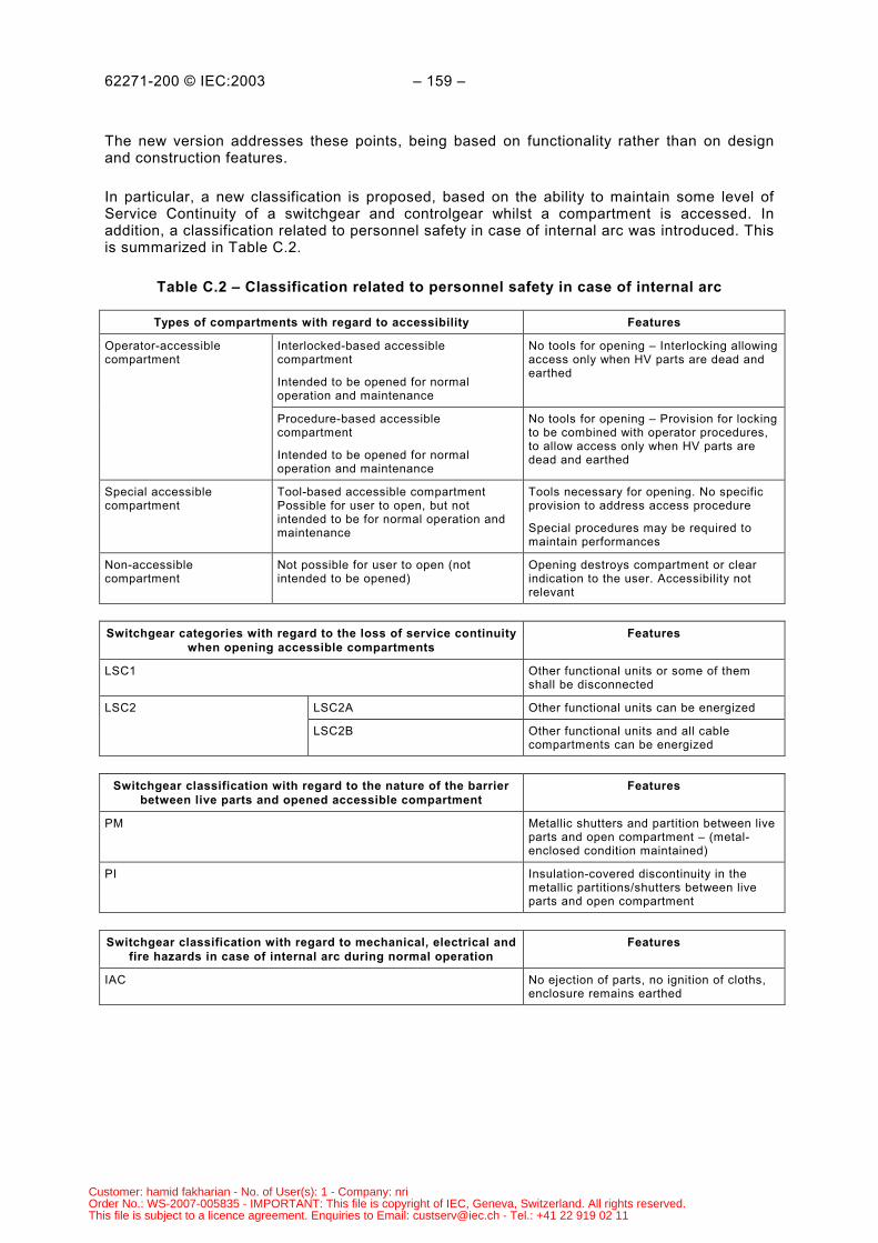
62271-200 © IEC:2003 – 159 –
The new version addresses these points, being based on functionality rather than on designand construction features.
In particular, a new classification is proposed, based on the ability to maintain some level ofService Continuity of a switchgear and controlgear whilst a compartment is accessed. Inaddition, a classification related to personnel safety in case of internal arc was introduced. Thisis summarized in Table C.2.
Table C.2 – Classification related to personnel safety in case of internal arc
Types of compartments with regard to accessibility Features
Interlocked-based accessiblecompartment
Intended to be opened for normaloperation and maintenance
No tools for opening – Interlocking allowingaccess only when HV parts are dead andearthed
Operator-accessiblecompartment
Procedure-based accessiblecompartment
Intended to be opened for normaloperation and maintenance
No tools for opening – Provision for lockingto be combined with operator procedures,to allow access only when HV parts aredead and earthed
Special accessiblecompartment
Tool-based accessible compartmentPossible for user to open, but notintended to be for normal operation andmaintenance
Tools necessary for opening. No specificprovision to address access procedure
Special procedures may be required tomaintain performances
Non-accessiblecompartment
Not possible for user to open (notintended to be opened)
Opening destroys compartment or clearindication to the user. Accessibility notrelevant
Switchgear categories with regard to the loss of service continuitywhen opening accessible compartments
Features
LSC1 Other functional units or some of themshall be disconnected
LSC2A Other functional units can be energizedLSC2
LSC2B Other functional units and all cablecompartments can be energized
Switchgear classification with regard to the nature of the barrierbetween live parts and opened accessible compartment
Features
PM Metallic shutters and partition between liveparts and open compartment – (metal-enclosed condition maintained)
PI Insulation-covered discontinuity in themetallic partitions/shutters between liveparts and open compartment
Switchgear classification with regard to mechanical, electrical andfire hazards in case of internal arc during normal operation
Features
IAC No ejection of parts, no ignition of cloths,enclosure remains earthed
Customer: hamid fakharian - No. of User(s): 1 - Company: nriOrder No.: WS-2007-005835 - IMPORTANT: This file is copyright of IEC, Geneva, Switzerland. All rights reserved.This file is subject to a licence agreement. Enquiries to Email: [email protected] - Tel.: +41 22 919 02 11
62271-200 © IEC:2003 – 161 –
In practice, valid Loss of Service Continuity categories of a switchgear and controlgear are:LSC1 , LSC1-PM; LSC1-PI, LSC2A-PM; LSC2A-PI; LSC2B-PM; LSC2B-PI , as detailed belowand in the following examples.
LSC: The LSC stands for level of Loss of Service Continuity when there is an openedmain-circuit compartment, i.e. the extent to which busbars/cables may be leftenergized, but not necessarily with power flowing through them.
LSC1: The 1 denotes that there is no service continuity at least for one functional unitother than the one containing the opened main circuit compartment.3
LSC2: The 2 denotes that there is service continuity of all functional units other thanthe one containing the opened main-circuit compartment. 3
LSC2A: The A denotes that there is no service continuity of the functional unit containingthe opened main-circuit compartment. This class can be achieved witha) a partition between each functional unit; andb) with a minimum of two compartments and one point of disconnection perfunctional unit.
LSC2B: The B denotes that the service continuity applies to other compartments of thefunctional unit containing the opened main circuit compartment. This class canbe achieved witha) a partition between each functional unit;b) a minimum of three compartments and two points of disconnection perfunctional unit.
LSC1-PM: The PM denotes that partitions and shutters are metallic.LSC2B-PI: The PI denotes that at least one partition or shutter is insulation.
The recommended approach to specify or describe a metal-enclosed switchgear andcontrolgear according to the standard, should be the top-down approach
Functionality
– Which pattern is needed (type of functions, fixed or removable, architecture andcompartments needed, need for maintenance)?
Service continuity and condition for accessibility
– Which compartments need not be opened?– If any, which compartments must be of the accessible type? (3.107)– Controlled, procedure or tool-based accessibility needed?– Service continuity (power flow possible in other functional units when opening a
compartment? (category LSC1/2)– The possibility to keep cables energized? (category LSC2A/B)– Electrical field gone in opened compartment is needed? (class PM / PI)
___________3 If it is the busbar compartment, on single busbar equipment, that is opened, then the opened compartment is in
all functional units in that section of the busbar.
Customer: hamid fakharian - No. of User(s): 1 - Company: nriOrder No.: WS-2007-005835 - IMPORTANT: This file is copyright of IEC, Geneva, Switzerland. All rights reserved.This file is subject to a licence agreement. Enquiries to Email: [email protected] - Tel.: +41 22 919 02 11
62271-200 © IEC:2003 – 163 –
C.2 ANSI defined metal-clad
Metal-clad switchgear as defined in ANSI is, according to this standard, class LSC2B-PMmetal-enclosed switchgear and controlgear characterized by the following main additionalrequirements.
– The main switching devices are withdrawable parts equipped with self-aligning andself-coupling primary disconnection devices and disconnectable control and auxiliarycircuits.
– Separate compartments are provided for voltage transformers and control powertransformers. Busbar compartments are additionally divided between horizontally adjacentfunctional units.
– Specifically included is a metal barrier in front of, or a part of, the withdrawable part toensure that, when in the connected position, no high-voltage parts are exposed by theopening of a door.
– Main-circuit conductors and connections are shrouded with flame-resistant insulatingmaterial throughout.
– Mechanical interlocks are provided for protecting operators form the accidental discharge ofstored energy from withdrawable parts by any of the following means.a) Interlocks in the compartment to prevent the complete withdrawal of the switching
device from the compartment when the stored energy mechanism is charged.b) A suitable device provided to prevent the complete withdrawal of the switching device
until the closing function is blocked.c) A mechanism provided to automatically discharge the stored energy before or during
the process of withdrawing the switching device from the compartment. If the storedenergy is discharged before the switching device is moved from the connectedposition, an adjunct electrical interlock is required to prevent stored energy recharge.
– Locking means is provided to prevent moving the withdrawable switching device into theconnected position.
– Segregation of auxiliary circuits is by earthed metal barriers from all high-voltage parts withthe exception of short lengths of wire, such as at instrument transformer terminals.
– Main circuits of all voltage transformers include current-limiting fuses. Main circuit fusesprovided for protecting transformers are mounted in such a way that they must bedisconnected from the high-voltage circuit before access can be obtained. Provisions aremade for disconnecting or automatically earthing the low-voltage circuit of voltagetransformers when the high-voltage circuit is disconnected. Provisions are made forearthing of the high-voltage winding and/or fuses during the disconnection operation todissipate static charges.
C.3 Former IEC defined metal-clad in terms of IEC 62271-200 definitions
For the following commonly used designs, providing that relevant features and requirementsare fulfilled, the former classifications can be related to the new ones.
– Former IEC metal-clad with withdrawable circuit-breaker and metallic shutters is nowLSC2B-PM.
– Former IEC metal-clad with withdrawable circuit-breaker and insulation shutters is nowLSC2B-PI.
– Former IEC compartmented with withdrawable circuit-breaker is now LSC2B-PI.
Other former IEC compartmented or cubicle is either LSC1; LSC2A-PI or LSC2B-PI dependingon construction details.
Customer: hamid fakharian - No. of User(s): 1 - Company: nriOrder No.: WS-2007-005835 - IMPORTANT: This file is copyright of IEC, Geneva, Switzerland. All rights reserved.This file is subject to a licence agreement. Enquiries to Email: [email protected] - Tel.: +41 22 919 02 11
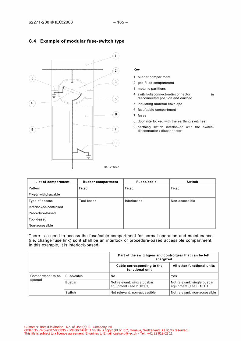
62271-200 © IEC:2003 – 165 –
C.4 Example of modular fuse-switch type
3
1
2
3
5
6
4
8 7
9
IEC 2480/03
Key
1 busbar compartment
2 gas-filled compartment
3 metallic partitions
4 switch-disconnector/disconnector indisconnected position and earthed
5 insulating material envelope
6 fuse/cable compartment
7 fuses
8 door interlocked with the earthing switches
9 earthing switch interlocked with the switch-disconnector / disconnector
List of compartment Busbar compartment Fuses/cable Switch
Pattern
Fixed/ withdrawable
Fixed Fixed Fixed
Type of access
Interlocked-controlled
Procedure-based
Tool-based
Non-accessible
Tool based Interlocked Non-accessible
There is a need to access the fuse/cable compartment for normal operation and maintenance(i.e. change fuse link) so it shall be an interlock or procedure-based accessible compartment.In this example, it is interlock-based.
Part of the switchgear and controlgear that can be leftenergized
Cable corresponding to thefunctional unit
All other functional units
Fuse/cable No Yes
Busbar Not relevant: single busbarequipment (see 3.131.1)
Not relevant: single busbarequipment (see 3.131.1)
Compartment to beopened
Switch Not relevant: non-accessible Not relevant: non-accessible
Customer: hamid fakharian - No. of User(s): 1 - Company: nriOrder No.: WS-2007-005835 - IMPORTANT: This file is copyright of IEC, Geneva, Switzerland. All rights reserved.This file is subject to a licence agreement. Enquiries to Email: [email protected] - Tel.: +41 22 919 02 11

62271-200 © IEC:2003 – 167 –
When opening the fuse/cable compartment of a functional unit, all other functional units canremain energized, and continuity is provided. However, the cable corresponding to the fusecompartment cannot remain energized.
There is a discontinuity in the metallic partitioning between the opened fuse/cable compartmentand live busbars, i.e. the insulating partition of the switch compartment.
The new classification is LSC2A- PI; the former classification was compartmented.
Customer: hamid fakharian - No. of User(s): 1 - Company: nriOrder No.: WS-2007-005835 - IMPORTANT: This file is copyright of IEC, Geneva, Switzerland. All rights reserved.This file is subject to a licence agreement. Enquiries to Email: [email protected] - Tel.: +41 22 919 02 11
62271-200 © IEC:2003 – 169 –
Bibliography
The following publications are listed in this standard for information.
IEC 60137:1995, Insulating bushings for alternating voltages above 1 000 V
IEC 60517:1990 Gas-insulated metal-enclosed switchgear for rated voltages of 72,5 kV andabove 4
IEC 60724:2000, Short-circuit temperature limits of electric cables with rated voltages of 1 kV(Um = 1,2 kV) and 3 kV (Um = 3,6 kV)
EN 50187:1996, Gas-filled compartments for a.c. switchgear and controlgear for rated voltagesabove 1 kV and up to and including 52 kV
IEEE C 37.20.7:2001, IEEE Guide for Testing Medium-Voltage Metal-Enclosed Switchgear forInternal Arcing Faults
___________
___________4 This publication is under revision and will be replaced with 62271-203 as soon as available.
Customer: hamid fakharian - No. of User(s): 1 - Company: nriOrder No.: WS-2007-005835 - IMPORTANT: This file is copyright of IEC, Geneva, Switzerland. All rights reserved.This file is subject to a licence agreement. Enquiries to Email: [email protected] - Tel.: +41 22 919 02 11

Customer: hamid fakharian - No. of User(s): 1 - Company: nriOrder No.: WS-2007-005835 - IMPORTANT: This file is copyright of IEC, Geneva, Switzerland. All rights reserved.This file is subject to a licence agreement. Enquiries to Email: [email protected] - Tel.: +41 22 919 02 11
Standards Survey
The IEC would like to offer you the best quality standards possible. To make sure that wecontinue to meet your needs, your feedback is essential. Would you please take a minuteto answer the questions overleaf and fax them to us at +41 22 919 03 00 or mail them tothe address below. Thank you!
Customer Service Centre (CSC)
International Electrotechnical Commission3, rue de Varembé1211 Genève 20Switzerland
or
Fax to: IEC/CSC at +41 22 919 03 00
Thank you for your contribution to the standards-making process.
Non affrancareNo stamp required
Nicht frankierenNe pas affranchir
A Prioritaire
RÉPONSE PAYÉE
SUISSE
Customer Service Centre (CSC)International Electrotechnical Commission3, rue de Varembé1211 GENEVA 20Switzerland
Customer: hamid fakharian - No. of User(s): 1 - Company: nriOrder No.: WS-2007-005835 - IMPORTANT: This file is copyright of IEC, Geneva, Switzerland. All rights reserved.This file is subject to a licence agreement. Enquiries to Email: [email protected] - Tel.: +41 22 919 02 11
Q1 Please report on ONE STANDARD andONE STANDARD ONLY . Enter the exactnumber of the standard: (e.g. 60601-1-1)
.............................................................
Q2 Please tell us in what capacity(ies) youbought the standard (tick all that apply).I am the/a:
purchasing agent R
librarian R
researcher R
design engineer R
safety engineer R
testing engineer R
marketing specialist R
other.....................................................
Q3 I work for/in/as a:(tick all that apply)
manufacturing R
consultant R
government R
test/certification facility R
public utility R
education R
military R
other.....................................................
Q4 This standard will be used for:(tick all that apply)
general reference R
product research R
product design/development R
specifications R
tenders R
quality assessment R
certification R
technical documentation R
thesis R
manufacturing R
other.....................................................
Q5 This standard meets my needs:(tick one)
not at all R
nearly R
fairly well R
exactly R
Q6 If you ticked NOT AT ALL in Question 5the reason is: (tick all that apply)
standard is out of date R
standard is incomplete R
standard is too academic R
standard is too superficial R
title is misleading R
I made the wrong choice R
other ....................................................
Q7 Please assess the standard in thefollowing categories, usingthe numbers:(1) unacceptable,(2) below average,(3) average,(4) above average,(5) exceptional,(6) not applicable
timeliness .............................................quality of writing....................................technical contents.................................logic of arrangement of contents ..........tables, charts, graphs, figures ...............other ....................................................
Q8 I read/use the: (tick one)
French text only R
English text only R
both English and French texts R
Q9 Please share any comment on anyaspect of the IEC that you would likeus to know:
............................................................
............................................................
............................................................
............................................................
............................................................
............................................................
............................................................
............................................................
............................................................
............................................................
............................................................
............................................................
Customer: hamid fakharian - No. of User(s): 1 - Company: nriOrder No.: WS-2007-005835 - IMPORTANT: This file is copyright of IEC, Geneva, Switzerland. All rights reserved.This file is subject to a licence agreement. Enquiries to Email: [email protected] - Tel.: +41 22 919 02 11

Customer: hamid fakharian - No. of User(s): 1 - Company: nriOrder No.: WS-2007-005835 - IMPORTANT: This file is copyright of IEC, Geneva, Switzerland. All rights reserved.This file is subject to a licence agreement. Enquiries to Email: [email protected] - Tel.: +41 22 919 02 11

ISBN 2-8318-7240-5
-:HSMINB=]\WYU\:ICS 29.130.10
Typeset and printed by the IEC Central OfficeGENEVA, SWITZERLAND
Customer: hamid fakharian - No. of User(s): 1 - Company: nriOrder No.: WS-2007-005835 - IMPORTANT: This file is copyright of IEC, Geneva, Switzerland. All rights reserved.This file is subject to a licence agreement. Enquiries to Email: [email protected] - Tel.: +41 22 919 02 11