international journal of advance engineering and...
TRANSCRIPT

International Journal of Advance Engineering and Research Development
Volume 5, Issue 04, April -2018
@IJAERD-2018, All rights Reserved 1024
Scientific Journal of Impact Factor (SJIF): 5.71 e-ISSN (O): 2348-4470 p-ISSN (P): 2348-6406
Transformer Health Monitoring And Control Through Arduino
1K.SRIDHAR,
2M.ASSARUDEEN,
3J.RANJITH KUMAR,
4 E.SARATHBABU
1 M.E. Assistant Professor Electrical Engineering,
2,3,4,5 B.Tech. Electrical Engineering, Rajiv Gandhi College Of Engineering & Technology
Abstract Our project is about design and implementation to monitor and record key parameters of a distribution
transformer like load currents, oil level, voltage level and temperature. The idea of on-line monitoring system integrates with
a stand alone Arduino and different sensors. It is installed at distribution transformer side and the above parameter are
recorded using the ARDUINO Microcontroller. The obtained parameters are processed and recorded in the system memory.
If any abnormality or an emergency situation occurs in the system, then the values will be displayed in the monitor according
to some predefined instructions programmed in the microcontroller. This mobile will help the transformers to operate
smoothly and identify problems before any catastrophic failure.
Keywords -Transformer health Monitoring, Distribution Transformer, Power system fault.
I. INTRODUCTION
In power systems, distribution transformer is electrical equipment which distributes power to the low voltage users
directly, and its operation condition is an important component of the entire distribution network operation. Operation of
distribution transformer under rated condition guarantees their long life .However their life is significantly reduced if they are
subjected to overloading, resulting in unexpected failures and loss of supply to a large number of customers thus effecting
system reliability. Overloading and ineffective cooling of transformers are the major causes of failure in distribution
transformers. Some major problems such as ordinary transformer measurement is too long and testing speed is not fast
enough, detection system itself is not reliable, timely detection data will not be sent to monitoring centres in time.
As we are using the microcontroller grid called ARDUINO the above mentioned fault can be easily determined and
the faults are displayed in the monitor.
II. TRANSFORMER FAULT ANALYSIS
There are some major faults occurs in the
transformer that should be regularly checked and monitored so it can associated with fault which follow as
A. Over Load
Over Load / Over current is the current flowing through the transformer resulting from faults on the power system.
Over current conditions are typically short in duration (less than two seconds) because protection relays usually operate to
isolate the faults from the power system.
B. Over / Under Voltage
The flux in the transformer core is directly proportional to the applied voltage and inversely proportional to the
frequency. Over voltage can occur when the per-unit ratio of voltage to frequency (Volts/Hz) exceeds 1.05 p .u at full load
and 1.10 p .u. at no load.
C. Temperature
Excessive load current alone may not result in damage to the transformer if the absolute temperature of the windings
and transformer oil remains within specified limits. Transformer ratings are based on a 24-hour average ambient temperature
of 30°C (86°F). Due to over voltage and over current, temperature of oil increases which causes failure of insulation of
transformer winding.
D. Oil Level Fault
Oil mainly used in transformer for two purposes one is for cooling of transformer and another use is for insulation
purpose. When temperature of transformer goes high, oil level in transformer tank decreases due to heating effect. For normal

International Journal of Advance Engineering and Research Development (IJAERD) Volume 5, Issue 04, April-2018, e-ISSN: 2348 - 4470, print-ISSN: 2348-6406
@IJAERD-2018, All rights Reserved 1025
operation of transformer oil level should maintain at required level. If oil level decreases beyond required level, it affect
cooling and insulation of the transformer.
III. BLOCK DIAGRAM OF TRANSFORMER HEALTH MONITORING AND CONTROL THROUGH ARDUINO
It consist of current transformer, power transformer, thermister, oil sensor, Arduino, LCD display, GSM modem and
relay. Normally in transformer, failure occurs due to voltage and current fluctuation, overheating, change in oil level etc. In
this project, to sense these fault we have used current and potential transformer, temperature sensor, oil sensor respectively.
All these sensors are connected Arduino. When fault occurs due to above any reason then change in ratings will be shown on
LCD.
IV. ARDUINO AT MEGA 2560
It is a microcontroller board based on the AT-Mega 2560 (datasheet). It has 54 digital input / output pins (of which
14 can be used as PWM outputs), 16 analog inputs, 4 UARTs (hardware serial ports), a 16 MHz crystal oscillator, a USB
connection, a power jack, an ICSP header, and a reset button.
T
R
A
N
S
F
O
R
M
E
R
CT
PT
OIL
LEVEL
TEMP
SENSOR
BRIDGE CIRCUIT
BRIDGE CIRCUIT
VOLTAGE SENSOR
CURRENT SENSOR
ARDUINO
AT MEGA 2560
BATTERY
BUZZER
RELAY
LCD
SINGLE PHASE CHARGE UNIT
CIRCUIT BREAKER

International Journal of Advance Engineering and Research Development (IJAERD) Volume 5, Issue 04, April-2018, e-ISSN: 2348 - 4470, print-ISSN: 2348-6406
@IJAERD-2018, All rights Reserved 1026
It contains everything needed to support the microcontroller; simply connect it to a computer with a USB cable or
power it with a AC-to-DC adapter or battery to get started. The Mega is compatible with most shields designed for the
Arduino Duemilanove or Diecimila.
A. Technical Specifications
Microcontroller ATmega2560
Operating Voltage 5V
Input Voltage
(recommended) 7-12V
Input Voltage (limit) 6-20V
Digital I/O Pins
54 (of which 15
provide PWM
output)
Analog Input Pins 16
DC Current per I/O Pin 20 mA
DC Current for 3.3V
Pin 50 mA
Flash Memory
256 KB of which 8
KB used by
bootloader
SRAM 8 KB
EEPROM 4 KB
Clock Speed 16 MHz
LED_BUILTIN 13
Length 101.52 mm
Width 53.3 mm
Weight 37 g
V. SENSORS
Sensor is a device that responds to a physical stimulus such has heat, light, sound, pressure, magnetism or a
particular motion and it transmits a resulting impulse as for measurement or operating a control.

International Journal of Advance Engineering and Research Development (IJAERD) Volume 5, Issue 04, April-2018, e-ISSN: 2348 - 4470, print-ISSN: 2348-6406
@IJAERD-2018, All rights Reserved 1027
A. Current Sensor
The ACS712 Current Sensors offered on the internet are designed to be easily used with micro controllers like the
Arduino. These sensors are based on the Allegro ACS712ELC chip. These current sensors are offered with full scale values
of 5A, 20A and 30A.
ACS712 current sensor operates from 5V and outputs analog voltage proportional to current measured on the
sensing terminals. You can simple use a microcontroller ADC to read the values.
B. Voltage Sensor
It is a simple circuit which turns a large voltage into a smaller one.Using just two resistors in series and an input
voltage, it can create an output voltage that is a fraction of the input.Within 250 V AC voltage can be measured. Linear range:
0-1000V 0-10mA(Sampling resistor is 100 ohm) Installation : PCB mounting (Pin Length> 3mm).
C. Oil Level Sensor
Sensors detect the level of liquids and other fluids and fluidized including slurries, granular materials and powders
that exhibit an upper level surface.
MFS-02 Magnetic Float Sensor
o No electrical contact with water
o Shock proof
POWER
SUPPLY
TEMPERATURE
SENSOR
BUZZER VOLTAGE
SENSOR
LCD CURRENT SENSOR
MAGNETIC
FLOAT SENSOR
ARDUINO
AT MEGA 2560

International Journal of Advance Engineering and Research Development (IJAERD) Volume 5, Issue 04, April-2018, e-ISSN: 2348 - 4470, print-ISSN: 2348-6406
@IJAERD-2018, All rights Reserved 1028
o Light weight, easy to use
o Corrosion free and rust free
D. Temperature Sensor
A temperature sensor is A device which is designed specifically to measure the hotness or coldness of an object. The
operating temperature range is from -55°c to 150°c. Lm35 is a precision temperature sensor with its output proportional to the
temperature (in °c). With lm35,the temperature can be measured more accurately than with a thermistor.
VI. ARDUINO CODING
Now let us discuss the function used in the programming to display the sensor values.
#define interval 1000
int val;
const int current sensor = 0;
int buttonstate = 1;
int voltagedivider = 2;
int tempPin = 3;
int floatsensor=2;
const int buzzer = 9;
float Vout=0.0;
float Vin=0.0;
float R1=30000.0;
float R2=7500.0;
int value=0;
int mVperAmp = 185; // use 100 for 20A Module and 66 for 30A Module
int RawValue= 0;
int ACSoffset = 2500;
double Voltage = 0;
double Amps = 0;
void setup()
{
Serial.begin(9600);
pinMode (buttonstate, INPUT); // initialize the button pin as a input
pinMode (tempPin, INPUT);
pinMode (voltagedivider, INPUT);
pinMode (floatsensor, INPUT_PULLUP);//Aurdino internal resistor 10k
pinMode (buzzer, OUTPUT);// Set buzzer - pin 9 as an output
pinMode (current sensor , INPUT);
}
void loop()
{
// voltage divider
value = analogRead(voltagedivider);
Vout = (value * 5.0) / 1024.0; // see text
Vin = Vout / (R2/(R1+R2));
vs=(38.333 / 1)*vin;
if (vin > 6.7 )

International Journal of Advance Engineering and Research Development (IJAERD) Volume 5, Issue 04, April-2018, e-ISSN: 2348 - 4470, print-ISSN: 2348-6406
@IJAERD-2018, All rights Reserved 1029
{
digitalWrite(relay ,HIGH);
delay(interval);
Serial.println("VOLTAGE HIGH");
}
else
{
digitalWrite(relay , LOW);
delay(interval);
Serial.println("VOLTAGE LOW");
}
Serial.print("OUTPUT V= ");
Serial.println(vin);
Serial.print("INPUT V= ");
Serial.println(vs);
}
{
//current sensor
RawValue = analogRead(analogIn);
Voltage = (RawValue / 1024.0) * 5000; // Gets you mV
Amps = ((Voltage - ACSoffset) / mVperAmp);
Serial.print("Raw Value = " ); // shows pre-scaled value
Serial.print(RawValue);
Serial.print("\t mV = "); // shows the voltage measured
Serial.print(Voltage,3); // the '3' after voltage allows you to display 3 digits after decimal point
Serial.print("\t Amps = "); // shows the voltage measured
Serial.println(Amps,3); // the '3' after voltage allows you to display 3 digits after decimal point
delay(2500);
}
{
//float sensor
buttonstate = digitalRead(floatsensor);
if (buttonstate == HIGH)
{
digitalWrite(buzzer, HIGH);
tone(buzzer, 1000);
Serial.println("OIL LEVEL - HIGH");
}
else
{
digitalWrite(buzzer, LOW);
noTone(buzzer);
Serial.println( "OIL LEVEL - LOW" );
}
{
//temperature sensor
val = analogRead(tempPin);
float mv = ( val/1024.0)*5000;
float cel = mv/10;
float farh = (cel*9)/5 + 32;
International Journal of Advance Engineering and Research Development (IJAERD) Volume 5, Issue 04, April-2018, e-ISSN: 2348 - 4470, print-ISSN: 2348-6406
@IJAERD-2018, All rights Reserved 1030
Serial.print("TEMPRATURE = ");
Serial.print(cel);
Serial.print("*C");
Serial.println();
Serial.print("TEMPRATURE = ");
Serial.print(farh);
Serial.print("*F");
Serial.println();
}
delay(1000);
}
Hence, the all values of sensors will be displayed in the monitor with the help of serial monitor.
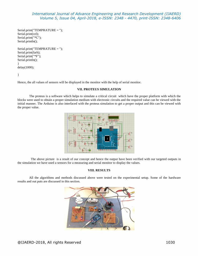
VII. PROTEUS SIMULATION
The proteus is a software which helps to simulate a critical circuit which have the proper platform with which the
blocks were used to obtain a proper simulation medium with electronic circuits and the required value can be viewed with the
initial manner. The Arduino is also interfaced with the proteus simulation to get a proper output and this can be viewed with
the proper value.
The above picture is a result of our concept and hence the output have been verified with our targeted outputs in
the simulation we have used a sensors for a measuring and serial monitor to display the values.
VIII. RESULTS
All the algorithms and methods discussed above were tested on the experimental setup. Some of the hardware
results and out puts are discussed in this section.

International Journal of Advance Engineering and Research Development (IJAERD) Volume 5, Issue 04, April-2018, e-ISSN: 2348 - 4470, print-ISSN: 2348-6406
@IJAERD-2018, All rights Reserved 1031
Fault No.1- Voltage level
When device detects low voltage or high voltage (set values), it will send the message to set number that
“Transformer no.--- Low/High Voltage Occur”, also it will trigger circuit breaker for cut off supply.
Fault No. 2- Over Load
When device detects current flowing through system high then it assumed that system is overloaded. After detect overloading
device send message “Transformer No. --- Overload Occur”, and will break system through line by opening circuit breaker.
Fault No.3- Oil Level In this system in transformer oil level is lowor high it sense the by using float sensor.
Fault No.4- Temperature
Temperature Ambient temperature of Transformer is high or it will be increase it sense through the sensor LM-35.
IX. CONCLUSION
Transformers are among the most generic and expensive piece of equipment of the transmission and distribution
system. Regular monitoring health condition of transformer not only is economical also adds to increased reliability. In the
past, maintenance of transformers was done based on a pre-determined schedule. Depending upon fault analysis a prototype
model of microcontroller based transformer health monitoring kit is developed in laboratory. With the advancement of signal
technology now it is possible to receive fault information of transformer through ARDUINO technology remotely to the
operator and authorities so one can able to take possible solution before converting fault in to fatal situation. Using digital
controller analysis results are regularly updated. During abnormal conditions exceeding specified limit information is
immediately analysed through ARDUINO and also to concerned authority for possible remedial action. This type of remote
observation of health condition of transformer not only increases the life of transformer but also increases mean down time of
transformer there by increased reliability and decreased cost of power system operations.
X. ACKNOWLEDGMENT
The authors would like to acknowledge the support from the Department of Electrical and Electronic Engineering,
Rajiv Gandhi College Of Engineering And Technology, Pondicherry University, Pondicherry. We would also like to
acknowledge Mr.K.SRIDHAR for their guidance.
REFERENCES
[1] Vadirajacharya. K, Ashish Kharche, Harish Kulakarni, Vivek Landage “Transformer Health Condition Monitoring
Through GSM Technology”, International Journal of Scientific & Engineering Research Volume 3, Issue 12, December-
2012.
[2] Anurudh kumar1, ashish raj2, abhishek kumar3, sikandar prasad4 & balwant kumar5 “method for monitoring of
distribution transformer”,1,2,3,4 &5 Dr. M.G.R, Educational and Research Institute, University, Chennai-600095.
[3] U.V.Patil1, Kathe Mohan2, Harkal Saurabh3, Warhade Nilesh4 “Transformer Health Condition Monitoring Using GSM
Technology”, Vol-2 Issue-2 2016 IJARIIE.

International Journal of Advance Engineering and Research Development (IJAERD) Volume 5, Issue 04, April-2018, e-ISSN: 2348 - 4470, print-ISSN: 2348-6406
@IJAERD-2018, All rights Reserved 1032
[4] A. z. loko1, a. i. bugaje2, a. a. bature3 “automatic method of protecting transformer using pic microcontroller as an
alternative to the fuse protection technique”, International Journal of Technical Research and Applications e-ISSN:2320-
8163, Volume 3, Issue 2 (Mar-Apr 2015), PP. 23-27.
[5] Karpe S R1, Sandeep Shelar2, Shraddha Garkad3, Shruti Lakade6 “Fault Detection and Protection of Transformer by
Using Microcontroller”, International Journal of Modern Trends in Engineering and Research.