international journal of computer science: theory and application
DESCRIPTION
The International Journal of Computer Science: Theory and Application (IJCSTA) is a bi-monthly, open access and peer-reviewed International Journal for academic researchers, industrial professionals, educators, developers and technical managers in the computer science field. The International Journal of Computer Science: Theory and Application invites original research papers, state-of-the-art reviews, and high quality technical notes, on both applied and theoretical aspects of computer science. The submitted papers must be unpublished and not under review in any other journal or conference.TRANSCRIPT

Vol. 1, No. 1, May 2014
Proposing a Formal Method for Workflow Modelling:Temporal Logic of Actions (TLA)Jose L. Caro1
1Computer Science Department, University of Malaga, Malaga, SpainEmail: [email protected]
ABSTRACTThe study and implementation of formal techniques to aid the design and implementation of Workflow ManagementSystems (WfMS) is still required. Using these techniques, we can provide this technology with automated reasoningcapacities, which are required for the automated demonstration of the properties that will verify a given model.This paper develops a formalization of the workflow paradigm based on communication (speech-act theory) byusing a temporal logic, namely, the Temporal Logic of Actions (TLA). This formalization provides the basictheoretical foundation for the automated demonstration of the properties of a workflow map, its simulation, andfine-tuning by managers.
KEYWORDSWorkflow — Workflow Management Systems — Temporal Logic — Temporal Logic of Actions.c© 2014 by Orb Academic Publisher. All rights reserved.
1. IntroductionWorkflow concept has been received with great interest in thebusiness world and in the area of software development. Work-flow technology and Workflow Management Systems (WfMS)are based on several disciplines: CSCW (Computer SupportedCooperative Work) and OIS (Office Information Systems) [1]are the main topics. Workflow includes a set of technologicalsolutions that allow us to automate work processes previously de-scribed by a formal model (called workflow map). The modellingof business processes into a workflow map is aimed at obtainingtotal automation and optimization of such processes.
Business processes reengineering, work simulation, organiza-tion modelling, resource management, and work automation aresome aspects under the general issue of what is nowadays knownas workflow technology [2].
The development of a workflow management system for anorganization is a highly complex process. Therefore, the workflowmap should be tested and validated before it is implemented; inother words, it should be analyzed prior to implementation. Mostcurrent workflow systems deal with this validation issue by usingsimulation modules that “execute” the model and examine thepossible problems before it is truly “executed” and implementedin real life [3].
Although these simulation modules are very useful for themanagement team to detect problems in the business processesrepresented by the workflow, it would be advisable to find othermore reliable methods. In other words, the model should allowand facilitate the automated demonstration of properties and char-
acteristics. For example: will any workflow never be executed?Will this workflow ever be executed? Is the operation carriedout with a specified time cost? Formal proving mechanisms willprovide a practical solution to these kinds of problems [4], [5].
The use of formal methods based on logic in workflow mod-elling can establish an automated, formal, and robust reasoningmechanism that will successfully provide insight into these issues(conflict, deadlock, reacheability, reliability, satisfability) [6], [7].
However, the efficiency of visual modelling tools should bepreserved and the introduction of new technology avoided. Toachieve this we have to establish a direct and unambiguous rela-tionship between current workflow paradigms and temporal logic.In this way, and depending on the particular case, we will be ableto use one or the other representational model: the visual/graphicmodel for design, and the formal model for automated handlingand analysis [8], [9].
In this paper we aim at approaching workflow modelling ina different way. Our object is to make a formalization of thelanguage/action paradigm [10], based on a extension of temporallogic. This extension is known as Temporal Logic of Actions(TLA) [11], and allows the easy modelling of transition states.
Our approach is as follows:
1. Specification of the workflow loop semantics (section 2.2).
2. Translation of the workflow loop into a state transitiondiagram (section 2.4.1).
3. The formalization in TLA of Searle’s state transition dia-gram (section 4).
1

Proposing a Formal Method for Workflow Modelling: Temporal Logic of Actions (TLA)
4. The formalization in TLA of workflow conections (section5).
This paper is organized as follows: we begin with a descrip-tion of workflow, workflow management systems, and the mod-elling of workflow processes (sec. 2). In section 2.2 we analyzethe basis of communication-based methodology (“speech-act”).In section 3 the TLA elements needed for the formalization aredescribed. The core of this paper is (section 4 and 5), where theTLA formalization of the language/action paradigm is developed.The last section includes some relevant conclusions and futurework.
2. Workflow and WfMSWorkflow includes a set of technological solutions aimed at au-tomating work processes that are described in an explicit processmodel called the workflow map. Workflow has a wide range ofpossibilities as demonstrated by group support and the automationof organizational processes.
In general terms we can define workflow as [7]:
workflow is comprised by a set of activities dealingwith the coordinated execution of multiple tasks de-veloped by different processing entities in order toreach a common objective
This definition of workflow does not indicate the nature of theprocessing entity, which, therefore, can be a person, a computer,a machine, etc. [12], [13].
This technology is made tangible as information technologysystems in the form of workflow management systems (WfMS).WfMS can be defined as [14]:
“A system that defines, creates, and manages auto-matically the execution of workflow models by theuse of one or more workflow engines in charge ofinterpreting process definitions (workflow maps), in-teracting with agents and, when required, invokingthe use of information systems involved in the work”
The workflow engine is in charge of coordinating the execu-tion of the workflow model, by determining the agents involved(whether humans or not), the data, and the applications required tocarry out the workflow. The WfMS is made up of many modules,but this paper pays special attention to the simulation modulewhich is used to test, via simulation, the workflow map beforeit is really implemented. Our aim is to propose a new reasoningworkflow module that is able to analyze the model before itsimplementation. This reasoning procedure will establish the con-sistency of the model by demonstrating the properties it shouldsatisfy [15].
To achieve this objective, the workflow map has to be ex-pressed in a way that allows such demonstrations. For this reasonwe will focus on demonstrating the possibility of translating work-flow technology into a logic tool.
2.1 Modelling techniques for workflow processesMany authors agree on splitting workflow methodologies intotwo main categories [2]:
• Activity-based methodology. These focus on modelling theactivities that will take place during the development of theworkflow [14].
• Communication-based methodologies. These stem fromSearle’s theory, known as “speech-acts” [16], [17].
Other techniques, like Petri Nets, Trigger Modelling, etc canbe found in the literature [18]-[23], although other authors en-globe this techniques in the activity based group.
As an example for good approach to time modelled, formalmethods, Petri nets and in general modelling techniques thatincludes a formal method for achieve demonstrations can befound in [24]-[27] but these methods are centered in activity basesmethodologies. Also we can introduce a new approach in the formof temporal logic formal methods into workflow technologies.
As our case study falls into the communication-based cate-gory, to demonstrate that the formal methods can be applied. Wewill now describe the basic principles underlying this methodol-ogy.
2.2 Communication-based methodologiesCommunication-based methodologies stem from the “Conversa-tion for Action” model developed by Medina-Mora, Winograd,and Flores [10], [28]. They view workflow as a sequence ofconversations between a client and a server. In this section, theagents involved are described as the client requiring a service thatwill be developed or performed by the server .
The communication previously described between client (Cli)and server (Svr) can be defined in four steps (figure 1):
• Request/preparation. The client requests an action andestablishes the criteria for completing it successfully.
• Negotiation. The conditions for being satisfied with thework to be done are negotiated.
• Development. The action is carried out by the server.
• Acceptance. The workflow loop is finished by acceptingthe work under the terms of satisfaction established in thesecond step.
Figure 1. Workflow loop
This model has two behaviors:
2
Proposing a Formal Method for Workflow Modelling: Temporal Logic of Actions (TLA)
• internal behavior or micro–level: the workflow individualbehavior.
• external behavior or macro–level : the relations inter work-flows.
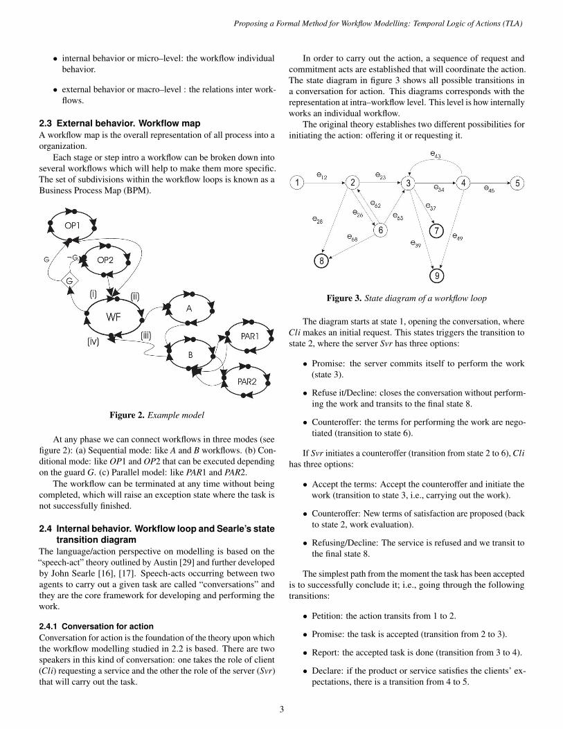
2.3 External behavior. Workflow mapA workflow map is the overall representation of all process into aorganization.
Each stage or step intro a workflow can be broken down intoseveral workflows which will help to make them more specific.The set of subdivisions within the workflow loops is known as aBusiness Process Map (BPM).
Figure 2. Example model
At any phase we can connect workflows in three modes (seefigure 2): (a) Sequential mode: like A and B workflows. (b) Con-ditional mode: like OP1 and OP2 that can be executed dependingon the guard G. (c) Parallel model: like PAR1 and PAR2.
The workflow can be terminated at any time without beingcompleted, which will raise an exception state where the task isnot successfully finished.
2.4 Internal behavior. Workflow loop and Searle’s statetransition diagram
The language/action perspective on modelling is based on the“speech-act” theory outlined by Austin [29] and further developedby John Searle [16], [17]. Speech-acts occurring between twoagents to carry out a given task are called “conversations” andthey are the core framework for developing and performing thework.
2.4.1 Conversation for actionConversation for action is the foundation of the theory upon whichthe workflow modelling studied in 2.2 is based. There are twospeakers in this kind of conversation: one takes the role of client(Cli) requesting a service and the other the role of the server (Svr)that will carry out the task.
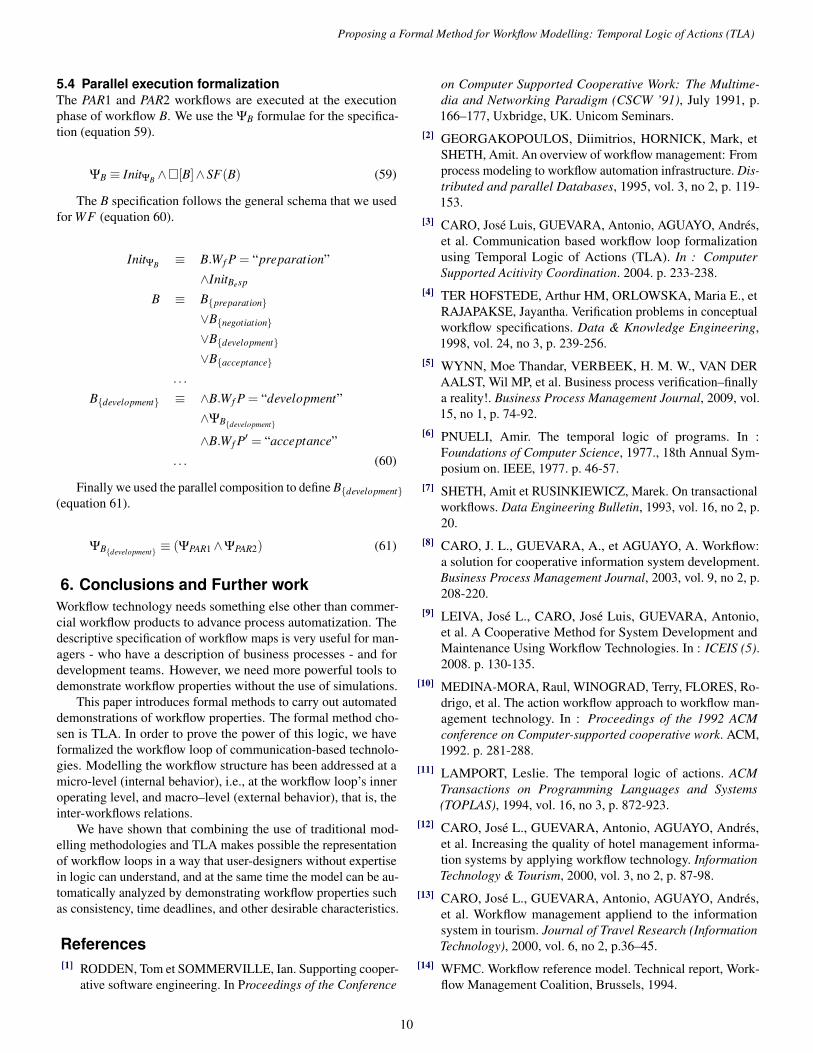
In order to carry out the action, a sequence of request andcommitment acts are established that will coordinate the action.The state diagram in figure 3 shows all possible transitions ina conversation for action. This diagrams corresponds with therepresentation at intra–workflow level. This level is how internallyworks an individual workflow.
The original theory establishes two different possibilities forinitiating the action: offering it or requesting it.
Figure 3. State diagram of a workflow loop
The diagram starts at state 1, opening the conversation, whereCli makes an initial request. This states triggers the transition tostate 2, where the server Svr has three options:
• Promise: the server commits itself to perform the work(state 3).
• Refuse it/Decline: closes the conversation without perform-ing the work and transits to the final state 8.
• Counteroffer: the terms for performing the work are nego-tiated (transition to state 6).
If Svr initiates a counteroffer (transition from state 2 to 6), Clihas three options:
• Accept the terms: Accept the counteroffer and initiate thework (transition to state 3, i.e., carrying out the work).
• Counteroffer: New terms of satisfaction are proposed (backto state 2, work evaluation).
• Refusing/Decline: The service is refused and we transit tothe final state 8.
The simplest path from the moment the task has been acceptedis to successfully conclude it; i.e., going through the followingtransitions:
• Petition: the action transits from 1 to 2.
• Promise: the task is accepted (transition from 2 to 3).
• Report: the accepted task is done (transition from 3 to 4).
• Declare: if the product or service satisfies the clients’ ex-pectations, there is a transition from 4 to 5.
3

Proposing a Formal Method for Workflow Modelling: Temporal Logic of Actions (TLA)
Another path involves transitions requiring negotiation, i.e., 3and 4 transitions. From state 3:
• Renege: Not performing the task accepted (from 3 to 7).
• Withdraw: Cli automatically withdraws the request (state3 to 9).
After Svr reporting that the work is concluded, several actionsare still possible:
• Declare: Cli declares the work has not been concludedsatisfactorily, and Svr has to do it again (stage 4 to 3).
• Withdraw: Cli automatically withdraws the petition (fromstate 4 to 9).
This complex structure makes it possible for a system tocomputationally coordinate a task.
3. Temporal Logic of ActionSince the first temporal logic was proposed by Pnueli [6] manyvariants have been developed. In this paper, we make use ofTemporal Logic of Actions (TLA) which allows us to modelstate transition diagrams in a relatively easy manner. Therefore,we now describe the basic principles described by Lamport [11]which are required to understand our work.
TLA combines two types of logic: Action logic, used torepresent relationships between states, and temporal logic, dealingwith the reasoning involved in an infinite sequence of states.
All TLA formulas are TRUE or FALSE in a behavior ( .=denotes equal to by definition). We define behavior σ as aninfinite sequence of states < s0,s1,s2, · · ·>, where each state sihas been assigned a corresponding variable.
3.1 Elements of State Logic in TLA3.1.1 VariablesAn infinite number of variable names (e.g., x or y) and a valueclass set that can be assigned to the variables are assumed. Thesevalue classes include strings, numbers, sets, and functions. If x isa variable, [[x]] is the function that semantically maps the valueof x in the states. Similarly, [[x]](s) is the function of the value ofx in the state s.
3.1.2 State and predicate functionsA state function is a non-Boolean expression built from variables,constants, and standard arithmetic operators. The semantics of[[ f ]], where f is a state function, consists of mapping states intovalues. To obtain the value of f in state s, we replace each variablexi of f with [[xi]](s).
Similarly, a predicate function or predicate P is a Booleanpredicate. [[P]] is an application of the set of states in a Booleanvalue. s fulfills P iff [[P]](s) is equal to TRUE.
3.1.3 ActionsAn action is a Boolean expression containing non-qualified primedvariables (such as x′), standard operators, and values. An actionrepresents an atomic operation of the system. Semantically, anaction A is true or false for a pair of states, and takes the primed
variables belonging to the second state. If we take an old states, a new state t, and an action A, we obtain [[A]](s, t), by firstreplacing each variable x with [[x]](s) and each variable x′ with[[x]](t) to later evaluate the expression. It is said that the state pair(s, t) is a A-step iff [[A]](s, t) is equal to TRUE.
3.1.4 Active action in a state and executionAn action A is said to be active in a state s if there is a state t suchthat (s, t) is a A-step (equation 1).
[[Enabled A]](s) .= ∃t ∈ σ : [[A]](s, t) (1)
An action A can be broken down into two logical formulae:G refers to the precondition, and B to the body of the action initself (eq. 2).
A≡ G∧B (2)
3.2 Elements of Temporal Logic in TLAIn TLA, the behavior of a system is modeled as an infinite se-quence of states, where their basic elements are actions and tem-poral logic. The actions help us in a simple and specific way tocontrol the potential next step. Temporal logic includes predicates,actions, logical operators, and temporal operators.
In order to define the semantics of temporal formulae, weneed to extend the semantic definition of the predicates whosevalue will be TRUE or FALSE in a given behavior.
A behavior satisfies the predicate P iff (eq. 3) is satisfied inthe first state.
[[P]](< s0,s1,s2, · · ·>)⇒ [[P]](s0) (3)
Similarly, a behavior satisfies the action A iff the first pair ofstates of the given behavior is an A-step (eq. 4).
[[A]](< s0,s1,s2, · · ·>)⇒ [[A]](s0,s1) (4)
3.2.1 The Always OperatorThe operator � (always) is the basic block of any temporal logic.Given a formula F , �F asserts that F is always TRUE (eq. 5):
[[�F ]](< s0,s1,s2, · · ·>).= ∀n≥ 0 : [[F ]](< sn,sn+1,sn+2, · · ·>)
(5)
From equations 3 and 4 we define a behavior σ that satisfies�P iff all the states of the behavior σ satisfy P. Similarly, abehavior σ satisfies �A iff all steps (si,si+1) are A-steps.
3.2.2 The Operator EventuallyAll temporal formulae can be constructed with traditional opera-tors of first-order logic and the operator �. However, it is usefulto define other operators such as ♦ (eventually). The formula ♦Fasserts that F is eventually TRUE (eq. 6):
[[♦F ]](< s0,s1,s2, · · ·>).= ∃n≥ 0 : [[F ]](< sn,sn+1,sn+2, · · ·>)
(6)
In other words, ♦F indicates that F is not always FALSE.Therefore:
♦F ≡ ¬�¬F (7)
4

Proposing a Formal Method for Workflow Modelling: Temporal Logic of Actions (TLA)
3.2.3 ValidityA formulae F is valid iff it is satisfied for all behaviors (eq. 8).
� F .= ∀σ ∈ S∞ : [[F ]](σ) (8)
S∞ denotes the set of all possible behaviors.
3.2.4 Specification in TLAAll previous definitions can be summed up in a single one to makea formal specification. A formal specification has the followinggeneral formula (eq. 9).
Π.= Init ∧�(A1∨A2∨·· ·∨An) (9)
A formula Π is TRUE in a behavior iff its first state satisfiesthe predicate Init and each step at least satisfies an action Ai.
Actions in TLA are allowed only if the predicate Enabled isTRUE and the context can be expressed as in equation 10.
[A]v.= A∨ v′ = v (10)
This expression indicates that a new v-step is a step whereeither A is an A-step or the values of v do not change. Bear inmind that v is a set of important variables in the action to beexecuted. The action v′ = v is usually called implicit stutteringaction.
Similarly, a non-stuttering execution can be defined:
〈A〉v.= A∨ v′ 6= v (11)
That is to say, the execution is a v–step if the step changes thevalues of some of the variables indicated in v.
3.2.5 Fairness OperatorsThe fairness operators are in charge of ensuring that ”nothingabnormal will happen”. There are two types: weak fairness (WF)and strong fairness (SF) operators.
Weak fairness. The weak fairness formula asserts that anaction has to be infinitely executed frequently if it is continuouslyenabled for an infinitely long time.
WFv(A).=�♦〈A〉v∨�♦¬Enabled〈A〉v (12)
Strong fairness. The strong fairness formula asserts that an ac-tion has to be infinitely executed frequently if it is often infinitelyenabled.
SFv(A).=�♦〈A〉v∨♦�¬Enabled〈A〉v (13)
Similarly, the following theorem can be established:
SFv(A)⇒WFv(A) (14)
3.2.6 Formal specification of a systemThe formal specification of a system is as follows (eq. 15):
Π.= Init ∧�[N]v∧L (15)
3.3 Formal approach to state diagram modellingAlthough it is possible to model any system with the structurespreviously described, it would be very useful in this case studyto establish a formal mechanism for modelling state diagramsin TLA, since this will be the basis for formalizing the lan-guage/action paradigm.
Lamport [30, 31] suggests the following formal approachto represent an action-predicate diagram. An action-predicatediagram is a diagram with a subset of nodes identified as initialnodes, where each node is labeled by a state predicate and everyedge is labeled by an action. The following notation is used:
• N: Set of nodes.
• I: Set of initial nodes.
• E(n): Set of edges originating at node n.
• d(e): Destination node of edge e.
• Pn: The predicate labeling node n.
• εe: The action labeling edge n.
The formula ∆, representing the diagram is defined as follows:
Init∆.= ∃n ∈ I : Pn
An.= ∃e ∈ E(n) : εe∧P′d(e)
∆.= Init∆∧∀n ∈ N : �[Pn⇒An]v (16)
If no specific label is attached to edge e, we take εe to beTRUE. When no set of initial nodes is explicitly specified, wetake I to be N. An is FALSE if no edges originate in node n.
From this definition, we can now represent the diagram inTLA.
4. Formalizing the language/actionparadigm
In order to formalize in TLA the state diagram introduced insection 2.4.1, its edges are labeled as ei j as shown in figure 3 inorder to follow the reference model later.
As a prior step, we will define what is understood by work.Work Wk is a quadruple expressed in the equation 17 where:
Wk.= {I,H,P,SC,V} (17)
• I: Information needed to carry out the task.
• H: Tools and methods needed for performing the task.
• P: Person, role or agent with the capacity to perform thetask.
• SC: Terms of satisfaction for the work to be consideredcompleted.
• V : Set of state variables belonging to the workflow.
5

Proposing a Formal Method for Workflow Modelling: Temporal Logic of Actions (TLA)
Each of these sub-variables is denoted as W k.I, W k.H, W k.P,W k.SC, W k.V , respectively, where W k is the work element.
The set of nodes in our diagram will be denoted by Ni, wherei is the number of the current state in the figure 3 (eq. 18).
N .= {N1,N2,N3,N4,N5,N6,N7,N8,N9} (18)
The initial state will be N1, since communication starts there.Therefore:
I .= {N1} (19)
In this way, and bearing in mind the equation to be satisfiedin the initial state, we have:
Init∆.= ∃n ∈ I : Pn (20)
Therefore, to complete the definition of the initial state wehave to give meaning to PN1 , and this has to be done in the formof equation (eq. 21).
PN1.= DetectTrigger(Type,Origine,Workflow)∧
Work f low = IDWF ∧Type ∈ TWFID∧Origine = A
(21)
This predicate indicates that the workflow will start when anevent coming from agent A is triggered and detected (DetectTrig-ger). From this point on, the agent A corresponds to the clientCli, and the event is a request for service identified as IDWF andcorresponding to the workflow.
Once the definition of the initial state N1 is completed, wecan define the next state variables belonging to the set V . Forsimplicity sake, we will not follow the notation but rather theprefix V :
• W kS: State of the work.
• W f S: Current state of the workflow.
• W f P: Current phase of the workflow.
• Wk: The variable representing the current work.
• XWk: External work proposed by A (where A is the work-flow’s client).
• W fCli: Workflow client.
• W f Svr: Workflow server.
Once the workflow has started, there is a transition to stateN2 through edge e12. This edge assigns the variables shown inequation 22.
e12.= W ′k = XWk ∧W f P′ = “preparation”∧W f S′ = “active”∧W kS′ = “feasibility study”∧W fCli′ = A
∧W f Svr′ = SelectAgent(OrgDB,B) (22)
The workflow is still in progress and the task is assigned to thevariable that records it within the system. The workflow IDWF
is now instantiated and the requested external work is assigned tothe execution model. This variable includes work XWk and theserver B (Srv), which up to this point was unknown, as well asthe initial terms of satisfaction XW k.SC.
To assign or chose the server, we will use the function Selec-tAgent(OrgDB,B) that will select an agent from the organizationamong those fulfilling B type requirements (this function willhave to access the knowledge base of the organization OrgDB).
The workflow is now at state N2. In this state, the work Bwill perform has to be evaluated. The petition and result of such anevaluation will be represented by the function EvalWork(Wk,Agent).
This function has two parameters, the work to be evaluatedWk and the agent in charge of such an evaluation. It also includesthe option for the evaluating agent to modify or make proposalsto change the response state. This response is obtained fromCounterOffer(Wk,Agent) that returns a new offer of the work Wkfrom the agent. It is possible to return: Commitment, counteroffer,Decline or cancel.
In this way PN2 will be in charge of carrying out the workevaluation.
PN2.= S = EvalWork(Wk,B)∧
(S = “Commitment”∨ S = “Counteroffer”∨ S = “Decline”) (23)
From state N2 we can advance through edges e22, e26 and e28.Edge e28 leads to state N8, which is a final state of uncom-
pleted termination of the workflow and comes from state 2 due toa decline of the offer (eq. 24).
e28.= S = “decline”∧W f P′ = “preparation”∧W f S′ = “abort”∧W kS′ = “Svr aborts” (24)
Consequently, a predicate that will abort the execution of theworkflow will be used in N8. This will trigger an exception so thatthe system can take appropriate actions (eq. 25). This possibilityis only open if the evaluation leads to “decline”.
PN8.= ExceptionWf (IDWF,“abort work”,Wk) (25)
In this state, the function ExceptionWf is used. This triggersthe exception of aborting the task, and goes back to TRUE whencompleted.
The edge e26 corresponds to a counteroffer from B after theevaluation done in PN2 . In this way the assignation of state vari-ables is as shown in equation 26.
e26.= S = “counteroffer”∧W f P′ = “negotiation”∧W f S′ = “active”∧W kS′ = “negotiation – Svr study the proposals”∧W k
′ = CounterOffer(Wk,W f Svr)
(26)
6

Proposing a Formal Method for Workflow Modelling: Temporal Logic of Actions (TLA)
In state N6 another evaluation is carried out, but this time isdone by A (PN6 . This is shown in equation 27).
PN6.= S = EvalWork(Wk,W fCli)∧
(S = “accepted”∨ S = “counteroffer”∨ S = “decline”) (27)
From state 6 we have three options: go to state 2 so that Breconsiders the offer made by the agent A (eq. 28), or it refusesit and goes to state 8, where the incomplete termination will callfor exception (eq. 29).
e62.= S = “counteroffer”∧W f P′ = “negotiation”∧W f S′ = “active”∧W kS′ = “negotiation - Cli study the proposals”∧W k
′ = ConunterOffer(Wk,W fCli)
(28)
e68.= S = “decline”∧W f P′ = “negotiation”∧W f S′ = “aborted”∧W kS′ = “Cli refuse the work” (29)
The third option open to A is to accept the current workWk, modified by B in this case, and transit to state N3 (eq. 30).Similarly, if the evaluation leads to B accepting the work, wecould directly go from state N2 to N3, (eq. 31).
e63.= S = “accept”∧W f P′ = “development”∧W f S′ = “execution”∧W kS′ = “accepted” (30)
e23.= S = “accept”∧W f P′ = “development”∧W f S′ = “execution”∧W kS′ = “accepted” (31)
Both equations are similar and do not have any effect on thevariable Wk, which represents the current work, whether this isthe original one or a counteroffer made by A or B (we assumethat the equation 10 has been applied, i.e., if the work does notchange, the variable preserves its value in the next state).
In order to define PN3 we have to use some back-up functionsthat will enable us to express the semantics of this state. Thesefunctions are :
• Trigger(ti,Wf ): trigger ti to enable the sub-workflow Wf .
• Completed(Wf ): TRUE if Wf has been satisfactorily com-pleted.
• Aborted(Wf ): TRUE if Wf has terminated as abort.
• Abort(X): TRUE if X aborts the workflow.
Let us bear in mind that in this state all subtasks have tobe run for the workflow to be completed. In addition, one ofthe following has to take place: a) all subtasks ai have to becompleted; b) the incorrect termination of some subtasks has tobe detected; or c) the client aborts the workflow.
Let W k.ai be each of the subtasks comprising the task of aworkflow Wk, then PN3 is defined as (eq. 32 and 33):
PN3.= ∀(ai ∈Wk, ti/ti = Trg(ai)) Trigger(ti,W k.ai)
∧(ExecutionPredicate) (32)
ExecutionPredicate .= �∀ai ∈Wk/Completed(W k.ai)
∨�∃ai ∈Wk/Aborted(W k.ai)
∨Abort(W kCli) (33)
It is important to bear in mind that this equation can be appliedto the states where the task to be carried out is evaluated, sincesuch evaluation can give rise to a explosion of subtasks.
Two options are possible: aborting the execution and going tostate N7 or N9 depending on who aborted or going to evaluationstate N4. These cases are expressed in equations 34, 35, and 36,respectively.
e39.= ∃ai ∈Wk/
(W k.ai.W f S = “aborted”∧W k.ai.W kS = “Svr refuses the work”)∧(W f P′ = “execution”∧W f S′ = “aborted”∧W kS′ = “Svr refuses the work”) (34)
e37.= ∃ai ∈Wk/
(W k.ai.W f S = “aborted”∧W k.ai.W kS = “Cli refuses the work”)∧(W f P′ = “execution”∧W f S′ = “aborted”∧W kS′ = “Cli refuses the work”) (35)
e34.= ∀ai ∈Wk/
(W k.ai.W f S = “accepted”∧W k.ai.W kS = “completed”)∧(W f P′ = “evaluation”∧W f S′ = “active”∧W kS′ = “Cli’s final evaluation”) (36)
State N4 consists in evaluating the final work (see equation37) using a predicate named EvalReport.
PN4.= EvalReport(Wk,B) = “correct”∨ EvalReport(Wk,B) = “incorrect”∨ ExceptionWf (IDWF,“abort work”,Wk) (37)
If the work satisfies the terms, there is a transit to a final andsuccessful state N5. On the other hand, if it does not, we go back
7

Proposing a Formal Method for Workflow Modelling: Temporal Logic of Actions (TLA)
to the subtask execution state (this path is optional) and if it isaborted, it leads to N9. These cases are expressed in equations 38,39, and 40.
e49.= W f P′ = “evaluation”∧W f S′ = “aborted”∧W kS′ = “Cli rejects the work” (38)
e45.= W f P′ = “Complete”∧W f S′ = “Completed”∧W kS′ = “work accepted for complete” (39)
e43.= W f P′ = “Execution”∧W f S′ = “Active”∧W kS′ = “work not accepted for complete :
reexecute” (40)
State N5 only has to send a completed signal (eq. 41).
PN5.= ExceptionWf (IDWF,“Completed WF successful”,Wk)
(41)
Once these definitions are completed and the model equationsare applied to formalize a state diagram (eq. 16) we obtain theformal representation.
5. Formalizing the language/actionparadigm as external behavior
As a prior step, we will define what is understood by work. Workw is a quadruple expressed in the equation w .
= {I,H,P,SC,V}where: I: Information needed to carry out the task. H: Tools andmethods needed to perform the task. P: Person, role or agent withthe capacity to perform the task. SC: Terms of satisfaction forthe work to be considered completed. V : Set of state variablesbelonging to the workflow.
Each of these sub-variables is denoted as W k.I, W k.H, W k.P,W k.SC, W k.V , respectively, where W k is the work element.
Also we define a set of workflow attributes that can be usedas control variables for its execution (these attributes are includein V ): W kS: State of the work. W f S: Current state of the work-flow. W f P: Current phase of the workflow. Wk: The variablerepresenting the current work. XWk: External work proposed byA (where A is the workflow’s client). W fCli: Workflow client.W f Svr: Workflow server.
At this point we can get the workflow behavior formalization.We use the example from figure 2 to illustrate how the mainprimitives formalize in TLA. We use the Wf P and Wf S workflowattributes for the specification. The control variable Wf P thatcontains the actual worflow phase is as follows:
Wf P ∈ {“preparation”,“negotiation”,“development”,“acceptance”,“ f inal”}
Wf S represents the internal status value for a workflow. Thisvariable is equal to “finished” when the workflows is terminated.
Also for the sub–workflows sequentiation into each phasewe use the control attribute sec. This variable stores the actualexecution position at each workflow phase. The sec type is anarray that can be noted with Wf .sec if it has only one position orWf .sec[1],Wf .sec[2], . . .Wf .sec[n] that specifies multiples waysof execution.
5.1 Workflow loop formalizationWith these elements we can formalize the case study in TLA. Forthe formalization we use the following notation:
• ΨWF a formal specification of workflow WF .
• WF the relationship with the following workflow state.
• InitΨWF initial condition for workflow execution. Thiscondition is composed by InitWF (initial condition for workvariables of workflow WF) and InitΨ or initial conditionfor WF control variables. Therefore InitΨWF = InitWF ∧InitΨ.
• WF{phase name} the equation that defines the behavior atworkflow level for each phase. WF{negotiation} correspondswith the negotiation phase specification. If the specificationdoes not exists its value will be WF{phase name} = > andtherefore always correct.
• ΨWF{phase name} corresponds with the phase specification.
• Ex(WF{phase name}) corresponds with the execution levelspecification of ΨWF{phase name} . This is an atomic sub–workflowand therefore equivalent at the definition level with the gen-eral formulae ΨWF . We use this term to nest specifications.
• f corresponds with the set of variables used by workflowboth control variables f<control> and work variables f<WF>
( f = f<control>∪ f<WF>).
To begin with the WF specification we define the generalformulae ΨWF (equation 42).
ΨWF ≡ InitΨWF ∧�[WF ] f
∧SF(WF{preparation})
∧SF(WF{negotiation})
∧SF(WF{development})
∧SF(WF{acceptance}) (42)
The initial state is the one at both control variables and workvariables of WF (to simplify we do not use this type of variable).This state indicates that the workflow is in the “preparation” phase(equation 43).
InitΨWF ≡ InitΨ∧ InitWF
InitΨ ≡ Wf P = “preparation” (43)
The workflow execution behavior consists in a sequentialexecution for each phase. Each phase executes its specification;
8

Proposing a Formal Method for Workflow Modelling: Temporal Logic of Actions (TLA)
and when it finishes then the workflow transits to the next phaseuntil the workflow has bee correctly completed (equation 44).
WF ≡ ∨WF{preparation}
∨WF{negotiation}
∨WF{development}
∨WF{acceptance} (44)
Each specification can be found in equations 45, 46, 47 and48.
WF{preparation} ≡ Wf P = “preparation”∧ΨWF{preparation}
Wf P′ = “negotiation”∧Unchg< f−{W f P}> (45)
WF{negotiation} ≡ Wf P = “negotiation”∧ΨWF{negotiation}
Wf P′ = “development”∧Unchg< f−{W f P}> (46)
WF{development} ≡ Wf P = “development”∧ΨWF{development}
Wf P′ = “acceptance”∧Unchg< f−{W f P}> (47)
WF{acceptance} ≡ Wf P = “acceptance”∧ΨWF{acceptance}
Wf P′ = “ f inal”∧Unchg< f−{W f P}> (48)
5.2 Sequential tasks formalizationContinuing with the example, we formalize tasks A and B whereexecution must be sequential. We use the sec attribute, whichnotes the actual execution sequence into each phase.
The general equation begins with a development phase ΨWF{development}(equation 49).
ΨWF{development} ≡ InitΨWF{development}
∧�[Ex(WF{development}] f
∧SF(A)
∧SF(B) (49)
The initial state variables has an effect on the sequential step(equation 50).
InitΨWF{development} ≡ WF{dev.}.sec = “A”∧InitWF{dev.} (50)
We used operator ∧ and ∨ following Lamport’s recommendation [31]Unchg is ’Unchanged operator’ in TLA
The execution is based on sub-workflow specifications A andB (equations 51, 52, 53 and .
Ex(WF{development} ≡ A∨B (51)
A ≡ ∧WF{development}.sec = “A”
∧ΨA∧WF{development}.sec′ = “B”∧Unchg< f−WF{development}.sec> (52)
B ≡ ∧WF{development}.sec = “B”
∧ΨB∧WF{development}.sec′ = “end”∧Unchg< f−WF{development}.sec> (53)
5.3 Conditional task formalizationThe tasks OP1 and OP2 are executed depending preconditionG at WF preparation phase. The equation 54 specifies how thisphase works and the fairness section specifies that both OP1 andOP2 will be executed eventually if infinitely often they are activefor its execution.
ΨWF{preparation} ≡ InitWF{preparation}
∧�[Ex(WF{preparation})] f
∧(WF(OP1)∨WF(OP2)) (54)
We used G and the predicate InitWF{preparation} to decide aboutthe execution for this sub–workflows (equation 55).
InitWF{prep.} ≡ (G→WF{prep.}.sec = “OP1”)
∨(¬G→WF{prep.}.sec = “OP2”) (55)
The execution definition, using the initialitation formulae, is(equations 56, 57 and 58):
Ex(WF{preparation}) ≡ (G→ OP1)∧(¬G→ OP2) (56)
OP1 ≡ WF{preparation}.sec = “OP1”∧ΨOP1
WF{preparation}.sec′ = “ f in”∧Unchg< f−sec> (57)
OP2 ≡ WF{preparation}.sec = “OP2”∧ΨOP2
WF{preparation}.sec′ = “ f in”∧Unchg< f−sec> (58)
9
Proposing a Formal Method for Workflow Modelling: Temporal Logic of Actions (TLA)
5.4 Parallel execution formalizationThe PAR1 and PAR2 workflows are executed at the executionphase of workflow B. We use the ΨB formulae for the specifica-tion (equation 59).
ΨB ≡ InitΨB ∧�[B]∧SF(B) (59)
The B specification follows the general schema that we usedfor WF (equation 60).
InitΨB ≡ B.Wf P = “preparation”∧InitBesp
B ≡ B{preparation}
∨B{negotiation}
∨B{development}
∨B{acceptance}
. . .
B{development} ≡ ∧B.Wf P = “development”∧ΨB{development}
∧B.Wf P′ = “acceptance”. . . (60)
Finally we used the parallel composition to define B{development}(equation 61).
ΨB{development} ≡ (ΨPAR1∧ΨPAR2) (61)
6. Conclusions and Further workWorkflow technology needs something else other than commer-cial workflow products to advance process automatization. Thedescriptive specification of workflow maps is very useful for man-agers - who have a description of business processes - and fordevelopment teams. However, we need more powerful tools todemonstrate workflow properties without the use of simulations.
This paper introduces formal methods to carry out automateddemonstrations of workflow properties. The formal method cho-sen is TLA. In order to prove the power of this logic, we haveformalized the workflow loop of communication-based technolo-gies. Modelling the workflow structure has been addressed at amicro-level (internal behavior), i.e., at the workflow loop’s inneroperating level, and macro–level (external behavior), that is, theinter-workflows relations.
We have shown that combining the use of traditional mod-elling methodologies and TLA makes possible the representationof workflow loops in a way that user-designers without expertisein logic can understand, and at the same time the model can be au-tomatically analyzed by demonstrating workflow properties suchas consistency, time deadlines, and other desirable characteristics.
References[1] RODDEN, Tom et SOMMERVILLE, Ian. Supporting cooper-
ative software engineering. In Proceedings of the Conference
on Computer Supported Cooperative Work: The Multime-dia and Networking Paradigm (CSCW ’91), July 1991, p.166–177, Uxbridge, UK. Unicom Seminars.
[2] GEORGAKOPOULOS, Diimitrios, HORNICK, Mark, etSHETH, Amit. An overview of workflow management: Fromprocess modeling to workflow automation infrastructure. Dis-tributed and parallel Databases, 1995, vol. 3, no 2, p. 119-153.
[3] CARO, Jose Luis, GUEVARA, Antonio, AGUAYO, Andres,et al. Communication based workflow loop formalizationusing Temporal Logic of Actions (TLA). In : ComputerSupported Acitivity Coordination. 2004. p. 233-238.
[4] TER HOFSTEDE, Arthur HM, ORLOWSKA, Maria E., etRAJAPAKSE, Jayantha. Verification problems in conceptualworkflow specifications. Data & Knowledge Engineering,1998, vol. 24, no 3, p. 239-256.
[5] WYNN, Moe Thandar, VERBEEK, H. M. W., VAN DERAALST, Wil MP, et al. Business process verification–finallya reality!. Business Process Management Journal, 2009, vol.15, no 1, p. 74-92.
[6] PNUELI, Amir. The temporal logic of programs. In :Foundations of Computer Science, 1977., 18th Annual Sym-posium on. IEEE, 1977. p. 46-57.
[7] SHETH, Amit et RUSINKIEWICZ, Marek. On transactionalworkflows. Data Engineering Bulletin, 1993, vol. 16, no 2, p.20.
[8] CARO, J. L., GUEVARA, A., et AGUAYO, A. Workflow:a solution for cooperative information system development.Business Process Management Journal, 2003, vol. 9, no 2, p.208-220.
[9] LEIVA, Jose L., CARO, Jose Luis, GUEVARA, Antonio,et al. A Cooperative Method for System Development andMaintenance Using Workflow Technologies. In : ICEIS (5).2008. p. 130-135.
[10] MEDINA-MORA, Raul, WINOGRAD, Terry, FLORES, Ro-drigo, et al. The action workflow approach to workflow man-agement technology. In : Proceedings of the 1992 ACMconference on Computer-supported cooperative work. ACM,1992. p. 281-288.
[11] LAMPORT, Leslie. The temporal logic of actions. ACMTransactions on Programming Languages and Systems(TOPLAS), 1994, vol. 16, no 3, p. 872-923.
[12] CARO, Jose L., GUEVARA, Antonio, AGUAYO, Andres,et al. Increasing the quality of hotel management informa-tion systems by applying workflow technology. InformationTechnology & Tourism, 2000, vol. 3, no 2, p. 87-98.
[13] CARO, Jose L., GUEVARA, Antonio, AGUAYO, Andres,et al. Workflow management appliend to the informationsystem in tourism. Journal of Travel Research (InformationTechnology), 2000, vol. 6, no 2, p.36–45.
[14] WFMC. Workflow reference model. Technical report, Work-flow Management Coalition, Brussels, 1994.
10

Proposing a Formal Method for Workflow Modelling: Temporal Logic of Actions (TLA)
[15] CARO, Jose Luis, GUEVARA, Antonio, GALVEZ, Sergio,et al. A Temporal Reasoning Approach of CommunicationBased Workflow Modelling. In: ICEIS (3). 2003. p. 245-250.
[16] SEARLE, John R. Speech acts: An essay in the philosophyof language. Cambridge university press, 1969.
[17] SEARLE, John R. A taxonomy of illocutionary acts. Lin-guistic Agency University of Trier, 1976. John R. Searle. Ataxonomy of illocutionary acts. In Keith Gunderson, editor,Language, Mind, and Knowledge. Minnesota Studies in thePhilosophy of Science, 1975., vol. 7, p. 344–369. Universityof Minnesota Press, Minneapolis, Minnesota.
[18] CASATI, Fabio, FUGINI, Mariagrazia, et MIRBEL, Isabelle.An environment for designing exceptions in workflows. In-formation systems, 1999, vol. 24, no 3, p. 255-273.
[19] DEPKE, Ralph, HECKEL, Reiko, et KUSTER, Jochen Malte.Roles in agent-oriented modeling. International Journal ofSoftware engineering and Knowledge engineering, 2001, vol.11, no 03, p. 281-302.
[20] GEPPERT, Andreas, TOMBROS, Dimitrios, et DITTRICH,Klaus R. Defining the semantics of reactive components inevent-driven workflow execution with event histories. Infor-mation Systems, 1998, vol. 23, no 3, p. 235-252.
[21] JOOSTEN, Stef. Trigger modelling for workflow analysis. In: Proceedings CON94: Workflow Management, Challenges,Paradigms and Products. 1994. p. 236-247.
[22] VAN DER AALST, W. M. P. Petri-net-based workflow man-agement software. In : Proceedings of the NFS Workshop onWorkflow and Process Automation in Information Systems.IEEE Computer Society, 1996. p. 114-118.
[23] VAN DER AALST, Wil MP et TER HOFSTEDE, ArthurHM. YAWL: yet another workflow language. Informationsystems, 2005, vol. 30, no 4, p. 245-275.
[24] SADIQ, Wasim et ORLOWSKA, Maria E. Analyzing pro-cess models using graph reduction techniques. Informationsystems, 2000, vol. 25, no 2, p. 117-134.
[25] VAN DER AALST, Wil MP. Formalization and verificationof event-driven process chains. Information and Softwaretechnology, 1999, vol. 41, no 10, p. 639-650.
[26] VAN DER AALST, Wil MP et TER HOFSTEDE, ArthurHM. Verification of workflow task structures: A petri-net-baset approach. Information systems, 2000, vol. 25, no 1, p.43-69.
[27] ZHUGE, Hai, CHEUNG, To-yat, et PUNG, Hung-Keng.A timed workflow process model. Journal of Systems andSoftware, 2001, vol. 55, no 3, p. 231-243.
[28] Terry Winograd. The language/action perspective. ACMTransactions on Office Information Systems, 1988, vol. 6,no 2, p. 83–86.
[29] John L. Austin. How to Do Things With Words. Oxford Uni-versity Press, Oxford, 1962.
[30] LAMPORT, Leslie. Tla in pictures. Technical Report 127,Digital Equipment Corporation, Systems Research Centre, 1September 1994.
[31] LAMPORT, Leslie. TLA in pictures. IEEE Transactions onSoftware Engineering, 1995, vol. 21, no 9, p. 768-775.
11