international journal of engineering science - unitn.itpiccolro/publications/ijes2012.pdf · in...
TRANSCRIPT
International Journal of Engineering Science 61 (2012) 112–128
Contents lists available at SciVerse ScienceDirect
International Journal of Engineering Science
journal homepage: www.elsevier .com/locate / i jengsci
Steady-state propagation of a Mode III crack in couple stresselastic materials
G. Mishuris a,c, A. Piccolroaz a,d,⇑, E. Radi b
a Institute of Mathematical and Physical Sciences, Aberystwyth University, Wales, UKb Dipartimento di Scienze e Metodi dell’Ingegneria, Università di Modena e Reggio Emilia, Italyc Rzeszow University of Technology, al. Powstanców Warszawy 12, 35-959, Rzeszów, Polandd Dipartimento di Ingegneria Meccanica e Strutturale, Università di Trento, Italy
a r t i c l e i n f o
Article history:Received 17 March 2012Accepted 17 April 2012Available online 24 July 2012
Keywords:Couple stress elasticityDynamic fractureSteady-state propagationMicrostructuresIntegral transform
0020-7225/$ - see front matter � 2012 Elsevier Ltdhttp://dx.doi.org/10.1016/j.ijengsci.2012.06.015
⇑ Corresponding author at: Institute of MathematE-mail address: [email protected] (A. Piccolroaz)
a b s t r a c t
This paper is concerned with the problem of a semi-infinite crack steadily propagating inan elastic solid with microstructures subject to antiplane loading applied on the crack sur-faces. The loading is moving with the same constant velocity as that of the crack tip. Weassume subsonic regime, that is the crack velocity is smaller than the shear wave velocity.The material behaviour is described by the indeterminate theory of couple stress elasticitydeveloped by Koiter. This constitutive model includes the characteristic lengths in bendingand torsion and thus it is able to account for the underlying microstructure of the materialas well as for the strong size effects arising at small scales and observed when the repre-sentative scale of the deformation field becomes comparable with the length scale of themicrostructure, such as the grain size in a polycrystalline or granular aggregate.
The present analysis confirms and extends earlier results on the static case by includingthe effects of crack velocity and rotational inertia. By adopting the criterion of maximumtotal shear stress, we discuss the effects of microstructural parameters on the stability ofcrack propagation.
� 2012 Elsevier Ltd. All rights reserved.
1. Introduction
In view of the discontinuous nature of many engineering materials, it is well known that the classical theory of elasticityis not adequate to accurately describe the stress and displacement fields at small scales (Morozov, 1984). The discrepancybetween the classical theoretical predictions and experimental results is found more pronounced for materials with acoarse-grain structure (Fleck, Muller, Ashby, & Hutchinson, 1994). The mechanical behaviour of most materials with micro-structure, like composites, cellular materials, foams, masonry, bone tissues, glassy and semicrystalline polymers, is stronglyinfluenced by the microstructural characteristic lengths, especially in the presence of large stress (or strain) gradients (Lakes,1986, 1995). These findings stimulated the development of generalized theories of continuum mechanics such as micropolarelasticity (Cosserat & Cosserat, 1909), indeterminate couple stress elasticity (Koiter, 1964) and more recently strain gradienttheories (Aifantis, 2011; Fleck & Hutchinson, 2001). An extensive review of various formats of gradient elasticity and theirperformance in static and dynamic applications can be found in Askes and Aifantis (2011).
Because of the characteristic lengths coming into play, the generalized theories predict dispersive wave propagation inmicrostructured media (Nowacki, 1985). Also the generalized theories predict different asymptotic behaviour for some com-ponents of the deformation and stress fields near singular points, compared to the classical elasticity theory (Morozov,
. All rights reserved.
ical and Physical Sciences, Aberystwyth University, Wales, UK, Tel.: +39 0461 282583..

G. Mishuris et al. / International Journal of Engineering Science 61 (2012) 112–128 113
1984). Correspondingly, the notion of energy release rate and J-integral needs to be generalized (Lubarda & Markenscoff,2000; Piccolroaz, Mishuris, & Radi, 2012). Interestingly, the relation between stress intensity factors for classic and CS elas-ticity discussed in details in Radi (2008) by means of the Wiener–Hopf technique was also found by Morozov and Nazarov(1980) and by Nazarov and Semenov (1980). The fact that microrotaions are bounded (and non-zero) at the crack tip has ledto the formulation of new fracture criteria (Morozov, 1984).
Due to the complexity of the equations of motion provided by the couple stress elastic theory with rotational inertia, onlyfew crack propagation problems have been considered in the literature, most of them have been solved numerically and veryfew closed form solution have been worked out. In particular, Parhi and Das (1970) used the couple stress theory to inves-tigate the stress distribution in a half-plane due to a moving line load on the surface. They assumed that the load is movingslower than both the longitudinal and transverse wave speeds of the elastic media (subsonic case) and found that the couplestress effect depends on the speed of the moving load, the couple-stress parameter, and the Poisson’s ratio. Han, Narasimhan,and Kennedy (1990) investigated dynamic propagation of a finite crack under mode-I loading in a micropolar elastic solid.Since the Wiener–Hopf technique can not be easily applied to finite crack problem, these authors solved numerically a pair oftwo-dimensional singular integral equations obtained by using an integral transform method. They provided solutions fordynamic stress intensity and couple stress intensity factors by using the obtained values of the strengths of the square rootsingularities in macrorotation and the gradient of microrotation at the crack tips. Itou (1981) considered the steady-statepropagation in plane strain condition for the case of vanishing rotational inertia and only one characteristic length, analysingthe influence of the crack tip speed on the asymptotics of the stress field. However, as already pointed out by Zhang, Huang,Chen, and Hwang (1998) and Radi (2008) for the static case, a simple asymptotic characterization of the crack tip fields is notsufficient to analyse the fracture behaviour of materials with microstructure. This is due to the fact that the asymptotic solu-tion is valid in a region close to the crack tip which is smaller than the characteristic lengths of the material, and thus it is ofscarce physical relevance. A full field analysis is then required in order to grasp the qualitative and quantitative behaviour ofthe solution in a larger region and to be able to judge on the stress level supported by the material.
The static full field solution obtained by Radi (2008) for a Mode III crack by using Fourier transforms and Wiener–Hopftechnique, shows that ahead of the crack tip within a zone smaller than the characteristic length in torsion, the total shearstress and reduced tractions occur with the opposite sign with respect to the classical LEFM solution, due to the relative rota-tion of the microstructural particles currently at the crack tip. However, this zone is found to have limited physical relevanceand to become vanishing small for a characteristic length in torsion of zero. In this limit case, the solution recovers the clas-sical KIII field with square root stress singularity. Outside the zone where the total shear stress is negative, the full field solu-tion exhibits a bounded maximum for the total shear stress ahead of the crack tip, whose magnitude was adopted as ameasure of the critical stress level for crack advancing. The introduction of a stress based fracture criterion thus defines acritical stress intensity factor, which increases with the characteristic length in torsion.
In this paper we analyse the steady-state propagation of a Mode III crack in couple stress elastic materials with finitecharacteristic lengths in bending and torsion. The static analysis is extended to the case of steady-state propagation inorder to study the effects of inertia and crack-tip speed on the stress and deformation fields, as well as the variationof the fracture toughness due to the presence of microstructure. The paper starts with the description of the fully dynam-ical version of the couple stress elastic model in Section 2, followed by an overview of some peculiar dynamical effectsthat this model is able to simulate. Differently from conventional elastic theories, this reasonably simple model can in-deed predict the dispersive character of shear wave propagation through elastic media with microstructures, for a specificrange of values of the microstructural parameters. Results provided in Section 2.1 concerning dispersive wave propaga-tion can thus be used to validate the characteristic length scales by comparison with atomistic and molecular dynamicssimulations (Maranganti & Sharma, 2007) or with experimental observations (Jakata & Every, 2008). Next, the problem ofsteady-state crack propagation under Mode III loading conditions applied to the crack surfaces is presented in Section 2.2.The analytical full-field solution is then addressed in Section 3, making use of Fourier transform and Wiener–Hopf tech-nique and basically following the approach introduced by Atkinson and Leppington (1977) for a plane stationary crackproblem. The crack tip is assumed to propagate at subsonic speed. Closed-form solutions are provided in Section 3.1for the special case of vanishing rotational inertia, and in Section 3.2 for an arbitrary but small value of the rotationalinertia parameter.
The stability of antiplane crack propagation is discussed in Section 4 by using the fracture criterion based on the maxi-mum shear stress hypothesis introduced by Radi (2008), which can find application in crack propagation also. It follows, in-deed, that propagation is unstable if the maximum shear stress occurring ahead of the crack tip during steady propagation isincreasing as the crack tip speed increases.
2. Problem formulation
Reference is made to a Cartesian coordinate system (0,x1,x2,x3) centred at the crack-tip at time t = 0. Under antiplaneshear deformation, the indeterminate theory of couple stress elasticity (Koiter, 1964) adopted here provides the followingkinematical compatibility conditions between the out-of-plane displacement u3, rotation vector u, strain tensor � and defor-mation curvature tensor v

114 G. Mishuris et al. / International Journal of Engineering Science 61 (2012) 112–128
�13 ¼12@u3
@x1; �23 ¼
12@u3
@x2; u1 ¼
12@u3
@x2; u2 ¼ �
12@u3
@x1; ð1Þ
v11 ¼ �v22 ¼12
@2u3
@x1@x2; v21 ¼ �
12@2u3
@x21
; v12 ¼12@2u3
@x22
: ð2Þ
Therefore, rotations are derived from displacements and the tensor field v turns out to be irrotational. According to thecouple stress theory, the non-symmetric Cauchy stress tensor t can be decomposed into a symmetric part r and a skew-sym-metric part s, namely t = r + s. In addition, the couple stress tensor l is introduced as the work-conjugated quantity of vT. Forthe antiplane problem within the couple stress theory �, r, s, v and l are purely deviatoric tensors. The reduced tractionsvector p and couple stress tractions vector q are defined as
p ¼ tT nþ 12rlnn � n; q ¼ lT n� lnnn; ð3Þ
respectively, where n denotes the outward unit normal and lnn = n � ln. The conditions of dynamic equilibrium of forces andmoments, neglecting body forces and body couples, write
@r13
@x1þ @r23
@x2þ @s13
@x1þ @s23
@x2¼ q€u3;
@l11
@x1þ @l21
@x2þ 2s23 ¼ J €u1;
@l12
@x1þ @l22
@x2� 2s13 ¼ J €u2; ð4Þ
where q is the mass density and J is the rotational inertia.Within the context of small deformations theory, the total strain � and the deformation curvature v are connected to
stress and couple stress through the following isotropic constitutive relations
r ¼ 2G�; l ¼ 2G‘2 vT þ gv� �
; ð5Þ
where G is the elastic shear modulus, ‘ and g the couple stress parameters introduced by Koiter (1964), with �1 < g < 1. Bothmaterial parameters ‘ and g depend on the microstructure and can be connected to the material characteristic lengths inbending and in torsion, namely
‘b ¼ ‘=ffiffiffi2p
; ‘t ¼ ‘ffiffiffiffiffiffiffiffiffiffiffiffi1þ g
p: ð6Þ
Typical values of ‘b and ‘t for some classes of materials with microstructure can be found in Lakes (1986, 1995). The limitvalue of g = �1 corresponds to a vanishing characteristic length in torsion, which is typical of polycrystalline metals. More-over, from the definitions (6) it follows that ‘t = ‘b for g = �0.5 and ‘t ¼ ‘ ¼
ffiffiffi2p
‘b for g = 0. The constitutive equations of theindeterminate couple stress theory do not define the skew-symmetric part s of the total stress tensor t, which instead isdetermined by the equilibrium Eq. (4)2,3. Constitutive Eq. (5) together with compatibility relations (1) and (2) give stressesand couple stresses in terms of the displacement u3:
r13 ¼ G@u3
@x1; r23 ¼ G
@u3
@x2; ð7Þ
l11 ¼ �l22 ¼ G‘2ð1þ gÞ @2u3
@x1@x2; l21 ¼ G‘2 @2u3
@x22
� g@u3
@x21
!; l12 ¼ �G‘2 @2u3
@x21
� g@2u3
@x22
!: ð8Þ
The introduction of (8) into (4)2,3 yields
s13 ¼ �G‘2
2D@u3
@x1þ J
4@€u3
@x1; s23 ¼ �
G‘2
2D@u3
@x2þ J
4@€u3
@x2; ð9Þ
where D denotes the Laplace operator. By means of (7) and (9), the equation of motion (4)1 becomes
GDu3 �G‘2
2D2u3 þ
J4
D€u3 ¼ q€u3: ð10Þ
2.1. Preliminary analysis on shear wave propagation
In this section we analyse the propagation of shear waves in a couple stress elastic material. We assume a solution of thegoverning Eq. (10) in form of a planar shear wave as follows
u3ðx1; x2; tÞ ¼ Ceiðkx�n�xtÞ; ð11Þ
where C is the amplitude, k is the wave number and x the radian frequency. A substitution of (11) into (10) yields the fol-lowing dispersive equation
k4 þ 2‘2 1�x2
h2
� �k2 � 2
‘2
x2
c2s¼ 0; ð12Þ
G. Mishuris et al. / International Journal of Engineering Science 61 (2012) 112–128 115
where cs ¼ffiffiffiffiffiffiffiffiffiG=q
pis the shear wave speed for classical elastic material and h ¼
ffiffiffiffiffiffiffiffiffiffi4G=J
p. By solving (12), we get the two equiv-
alent dispersive relations
k2 ¼ � 1‘2 1�x2h2
c2s
!þ 1‘2
ffiffiffiffiffiffiffiffiffiffiffiffiffiffiffiffiffiffiffiffiffiffiffiffiffiffiffiffiffiffiffiffiffiffiffiffiffiffiffiffiffiffiffiffiffiffiffiffiffi1�x2h2
c2s
!2
þ 2x2‘2
c2s
vuut ; x2 ¼ c2s
2k2ðk2
‘2 þ 2Þk2h2 þ 1
; ð13Þ
where h is a characteristic length given by h = cs/h. We obtain that the shear wave is dispersive and propagates with phasespeed
~c2 ¼ x2
k2 ¼c2
s
21�x2h2
0‘2
c2sþ
ffiffiffiffiffiffiffiffiffiffiffiffiffiffiffiffiffiffiffiffiffiffiffiffiffiffiffiffiffiffiffiffiffiffiffiffiffiffiffiffiffiffiffiffiffiffiffiffiffiffiffiffiffiffi1�x2h2
0‘2
c2s
!2
þ 2x2‘2
c2s
vuut264
375 ¼ c2
s
2k2‘2 þ 2
k2‘2h2
0 þ 1; ð14Þ
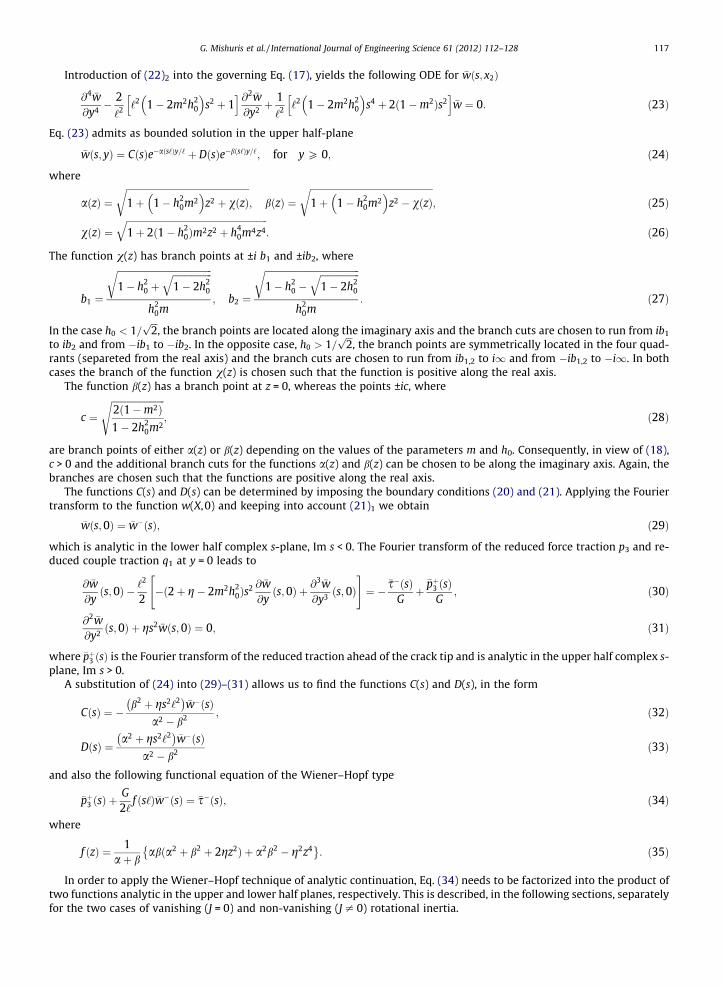
where h0 = h/‘is a dimensionless parameter. Note that the relation (14) was found by Ottosen, Ristinmaa, and Ljung (2000)for the special case of vanishing rotational inertia, h0 = 0.
The normalized shear wave speed ~c=cs as a function of the normalized frequency x‘/cs is shown in Fig. 1 for different val-ues of the parameter h0, which is a measure of the rotational inertia. In the case of vanishing rotational inertia, h0 = 0, thewave propagation is dispersive with monotonically increasing phase speed, as found by Ottosen et al. (2000) (see also Askes& Aifantis, 2011). In the presence of rotational inertia, h0 – 0, the dispersive character of the propagation is reduced until, forthe limiting case h0 ¼ 1=
ffiffiffi2p
, the wave propagation is non-dispersive as in classical elastic materials. Beyond this limit, thewave propagation is again dispersive but with decreasing phase speed. It is worth noticing that the same result was found byAskes and Aifantis (2011) in the framework of stable gradient elasticity. Similar behaviour was also reported by Georgiadisand Velgaki (2003) for Rayleigh wave propagation in CS material. In particular, they analysed the behaviour of dispersivecurves in the range 1=
ffiffiffiffiffiffi24p
< h0 <ffiffiffiffiffiffiffiffiffiffiffi10=3
pof the rotational inertia (or, in their notations, 0:25 < lh2=g < 20, where
l ¼ G; g ¼ G‘2=2 and h2 ¼ 3J=4q). However, the authors of the aforementioned papers did not discuss the limit value forthe parameter h0 separating the two essentially different regimes. Nevertheless, analysing the numerical results reportedby Georgiadis and Velgaki (Figs. 5 and 6 in their paper), one could expect that the limit value coincides with our findings.Since this value is found for two different wave problems (antiplane shear waves in the present case and plane strainRayleigh waves in their case), we believe that it may be a fundamental constant for CS materials. As it will be seen inSection 4, this limit value is also related to the stability of crack propagation.
It is also noted from Fig. 1 that, for low frequencies, x ? 0, the shear wave propagates with the same speed as in classicalelastic materials, ~c ¼ cs, because long wavelengths do not feel the microstructure. Vice versa, for high frequencies, x ?1,short wavelengths interact with the microstructure and the shear wave propagates with constant speed depending on therotational inertia, ~c ¼ cs=
ffiffiffi2p
h0. Consequently, in the range of rotational inertia 0 < h0 6 1=ffiffiffi2p
, the crack propagation is sub-sonic provided that the crack tip speed V is less than cs, whereas in the range h0 > 1=
ffiffiffi2p
, the crack propagation is subsonicsubject to the condition V < cs=
ffiffiffi2p
h0.
2.2. Steady-state crack propagation
We assume that the crack propagates with a constant velocity V straight along the x1-axis and is subjected to reducedforce traction p3 applied on the crack faces, moving with the same velocity V, whereas reduced couple traction q1 is assumedto be zero,
p3ðx1;0�; tÞ ¼ �sðx1 � VtÞ; q1ðx1;0
�; tÞ ¼ 0; for x1 � Vt < 0: ð15Þ
We also assume that the function s decays at infinity sufficiently fast and it is bounded at the crack tip. These requirementsare the same requirements for tractions as in the classical theory of elasticity.
h0 1 2
1.5
0
0.25
0.5
0.8
0 2 4 6 8 100.0
0.5
1.0
1.5
2.0
2.5
cc s
Fig. 1. Dispersive character of shear waves in couple-stress materials.

Subson ic regim e
Superson ic regim e
m 1
m1
2 h0
h01
2
0.0 0.5 1.0 1.5 2.00.0
0.5
1.0
1.5
2.0
h0
m
Fig. 2. Subsonic and supersonic regimes in the m � h0 plane.
116 G. Mishuris et al. / International Journal of Engineering Science 61 (2012) 112–128
It is convenient to introduce a moving framework X = x1 � Vt, y = x2. By assuming that the out of plane displacement fieldhas the form
u3ðx1; x2; tÞ ¼ wðX; yÞ; ð16Þ
then the equation of motion (10) writes:
1�m2� � @2w
@X2 þ@2w@y2 �
‘2
21� 2m2h2
0
� � @4w
@X4 � ‘2 1�m2h2
0
� � @4w
@X2@y2� ‘
2
2@4w@y4 ¼ 0; ð17Þ
where m = V/cs is the normalized crack velocity. We consider the subsonic regime (see Fig. 2), so that
0 6 m < min 1;1ffiffiffi2p
h0
: ð18Þ
According to (3), the non-vanishing components of the reduced force traction and reduced couple traction vectors alongthe crack line y = 0, where n = (0,±1,0), can be written as
p3 ¼ t23 þ12@l22
@X; q1 ¼ l21; ð19Þ
respectively. By using (7)2, (8)1,2, (9)2, and (19), the loading conditions (15) on the upper crack surface require the followingconditions for the function w:
@w@y� ‘
2
2@
@yð2þ g� 2m2h2
0Þ@2w
@X2 þ@2w@y2
" #¼ � 1
GsðXÞ; @2w
@y2 � g@2w
@X2 ¼ 0; for X < 0; y ¼ 0þ: ð20Þ
Ahead of the crack tip, the skew-symmetry of the Mode III crack problem requires
w ¼ 0;@2w@y2 � g
@2w
@X2 ¼ 0; for X > 0; y ¼ 0þ: ð21Þ
Note that the ratio g enters the boundary conditions (20) and (21), but it does not appear into the governing PDE (17).
3. Full field solution
In the present section the Wiener–Hopf analytic continuation technique (Noble, 1958; Freund, 1990) is used to obtain thefull field solution for a semi-infinite crack propagating in an infinite medium with constant velocity and subject to movingloading applied on the crack surfaces. Only the upper half-plane (y P 0) is considered due to the skew-symmetry of the prob-lem. Use of the Fourier transform and inverse transform is made. For the function w(X,y) they are
�wðs; yÞ ¼Z 1
�1wðX; yÞeisXdX; wðX; yÞ ¼ 1
2p
ZL
�wðs; yÞe�isXds; ð22Þ
respectively, where s is a real variable and the line of integration L will be defined later.
G. Mishuris et al. / International Journal of Engineering Science 61 (2012) 112–128 117
Introduction of (22)2 into the governing Eq. (17), yields the following ODE for �wðs; x2Þ
@4 �w@y4 �
2‘2 ‘2 1� 2m2h2
0
� �s2 þ 1
h i @2 �w@y2 þ
1‘2 ‘2 1� 2m2h2
0
� �s4 þ 2ð1�m2Þs2
h i�w ¼ 0: ð23Þ
Eq. (23) admits as bounded solution in the upper half-plane
�wðs; yÞ ¼ CðsÞe�aðs‘Þy=‘ þ DðsÞe�bðs‘Þy=‘; for y P 0; ð24Þ
where
aðzÞ ¼ffiffiffiffiffiffiffiffiffiffiffiffiffiffiffiffiffiffiffiffiffiffiffiffiffiffiffiffiffiffiffiffiffiffiffiffiffiffiffiffiffiffiffiffiffiffiffiffiffiffiffiffiffi1þ 1� h2
0m2� �
z2 þ vðzÞr
; bðzÞ ¼ffiffiffiffiffiffiffiffiffiffiffiffiffiffiffiffiffiffiffiffiffiffiffiffiffiffiffiffiffiffiffiffiffiffiffiffiffiffiffiffiffiffiffiffiffiffiffiffiffiffiffiffiffi1þ 1� h2
0m2� �
z2 � vðzÞr
; ð25Þ
vðzÞ ¼ffiffiffiffiffiffiffiffiffiffiffiffiffiffiffiffiffiffiffiffiffiffiffiffiffiffiffiffiffiffiffiffiffiffiffiffiffiffiffiffiffiffiffiffiffiffiffiffiffiffiffiffiffiffiffiffiffiffiffiffiffi1þ 2ð1� h2
0Þm2z2 þ h40m4z4
q: ð26Þ
The function v(z) has branch points at ±i b1 and ±ib2, where
b1 ¼
ffiffiffiffiffiffiffiffiffiffiffiffiffiffiffiffiffiffiffiffiffiffiffiffiffiffiffiffiffiffiffiffiffiffiffiffiffiffiffiffiffi1� h2
0 þffiffiffiffiffiffiffiffiffiffiffiffiffiffiffiffiffi1� 2h2
0
qrh2
0m; b2 ¼
ffiffiffiffiffiffiffiffiffiffiffiffiffiffiffiffiffiffiffiffiffiffiffiffiffiffiffiffiffiffiffiffiffiffiffiffiffiffiffiffiffi1� h2
0 �ffiffiffiffiffiffiffiffiffiffiffiffiffiffiffiffiffi1� 2h2
0
qrh2
0m: ð27Þ
In the case h0 < 1=ffiffiffi2p
, the branch points are located along the imaginary axis and the branch cuts are chosen to run from ib1
to ib2 and from �ib1 to �ib2. In the opposite case, h0 > 1=ffiffiffi2p
, the branch points are symmetrically located in the four quad-rants (separeted from the real axis) and the branch cuts are chosen to run from ib1,2 to i1 and from �ib1,2 to �i1. In bothcases the branch of the function v(z) is chosen such that the function is positive along the real axis.
The function b(z) has a branch point at z = 0, whereas the points ±ic, where
c ¼ffiffiffiffiffiffiffiffiffiffiffiffiffiffiffiffiffiffiffiffiffiffiffi2ð1�m2Þ1� 2h2
0m2
s; ð28Þ
are branch points of either a(z) or b(z) depending on the values of the parameters m and h0. Consequently, in view of (18),c > 0 and the additional branch cuts for the functions a(z) and b(z) can be chosen to be along the imaginary axis. Again, thebranches are chosen such that the functions are positive along the real axis.
The functions C(s) and D(s) can be determined by imposing the boundary conditions (20) and (21). Applying the Fouriertransform to the function w(X,0) and keeping into account (21)1 we obtain
�wðs;0Þ ¼ �w�ðsÞ; ð29Þ
which is analytic in the lower half complex s-plane, Im s < 0. The Fourier transform of the reduced force traction p3 and re-duced couple traction q1 at y = 0 leads to
@ �w@yðs;0Þ � ‘
2
2�ð2þ g� 2m2h2
0Þs2 @ �w@yðs;0Þ þ @
3 �w@y3 ðs;0Þ
" #¼ �
�s�ðsÞGþ
�pþ3 ðsÞG
; ð30Þ
@2 �w@y2 ðs;0Þ þ gs2 �wðs; 0Þ ¼ 0; ð31Þ
where �pþ3 ðsÞ is the Fourier transform of the reduced traction ahead of the crack tip and is analytic in the upper half complex s-plane, Im s > 0.
A substitution of (24) into (29)–(31) allows us to find the functions C(s) and D(s), in the form
CðsÞ ¼ �b2 þ gs2‘2� �
�w�ðsÞa2 � b2 ; ð32Þ
DðsÞ ¼a2 þ gs2‘2� �
�w�ðsÞa2 � b2 ð33Þ
and also the following functional equation of the Wiener–Hopf type
�pþ3 ðsÞ þG2‘
f ðs‘Þ �w�ðsÞ ¼ �s�ðsÞ; ð34Þ
where
f ðzÞ ¼ 1aþ b
abða2 þ b2 þ 2gz2Þ þ a2b2 � g2z4� �: ð35Þ
In order to apply the Wiener–Hopf technique of analytic continuation, Eq. (34) needs to be factorized into the product oftwo functions analytic in the upper and lower half planes, respectively. This is described, in the following sections, separatelyfor the two cases of vanishing (J = 0) and non-vanishing (J – 0) rotational inertia.
118 G. Mishuris et al. / International Journal of Engineering Science 61 (2012) 112–128
3.1. The case of vanishing rotational inertia J = 0
In the case of vanishig rotational inertia, we have J = 0 and consequently h0 = 0. The Wiener–Hopf Eq. (34) reduces to
�pþ3 ðsÞ þG2‘
f ðs‘Þ �w�ðsÞ ¼ �s�ðsÞ; ð36Þ
where
f ðzÞ ¼ 1aþ b
abðaþ bÞ2 � ðab� gz2Þ2n o
ð37Þ
and
aðzÞ ¼ffiffiffiffiffiffiffiffiffiffiffiffiffiffiffiffiffiffiffiffiffiffiffiffiffiffiffiffi1þ z2 þ vðzÞ
q; bðzÞ ¼
ffiffiffiffiffiffiffiffiffiffiffiffiffiffiffiffiffiffiffiffiffiffiffiffiffiffiffiffi1þ z2 � vðzÞ
q; vðzÞ ¼
ffiffiffiffiffiffiffiffiffiffiffiffiffiffiffiffiffiffiffiffiffiffi1þ 2m2z2
p: ð38Þ
The function v(z) has branch points at ±ib, where b ¼ 1=ðffiffiffi2p
mÞ, and the branch cuts are chosen to run from ± ib to ±i1 alongthe imaginary axis.
The function b(z) has a branch point at z = 0, whereas the points ±ic, where
c ¼ffiffiffiffiffiffiffiffiffiffiffiffiffiffiffiffiffiffiffiffiffiffi2ð1�m2Þ
qð39Þ
are branch points of either a(z) or b(z) depending on the values of the parameter m. Consequently, the additional branch cutsfor the functions a(z) and b(z) can be chosen to be along the imaginary axis.
It is noted that f(z) does not have any pole in the entire complex plane and has the following asymptotics at zero andinfinity along the real line
f ðzÞ ¼ 12ð1þ gÞð3� gÞjzj3 þ Oðjzj2Þ; z! �1; z 2 R; ð40Þ
f ðzÞ ¼ 2ffiffiffiffiffiffiffiffiffiffiffiffiffiffiffi1�m2p
jzj þ Oðjzj2Þ; z! 0; z 2 R: ð41Þ
Moreover, the only zero of f(z) along the real axis is at z = 0. Note that g = �1 is a special case as the behaviour of the functionf(z) at infinite differs and consequently the solution is different. We will not consider this limit case.
3.1.1. Wiener–Hopf factorizationIn order to apply the Wiener–Hopf technique of analytic continuation, Eq. (36) needs to be factorized into the product of
two functions analytic in the upper and lower half-planes, respectively.Instead of the function f(z), we will factorize the function
kðzÞ ¼ f ðzÞffiffiffiffiffiz2p
WðzÞ; ð42Þ
where
WðzÞ ¼ 12ð1þ gÞð3� gÞz2 þ 2
ffiffiffiffiffiffiffiffiffiffiffiffiffiffiffi1�m2p
: ð43Þ
It is noted that, along the real axis, the function k(z) has no zeros and has the following asymptotics at zero and infinity
kðzÞ ¼ 1þ OðjzjÞ; z! 0; z 2 R: ð44ÞkðzÞ ¼ 1þ Oðjzj�1Þ; z! �1; z 2 R; ð45Þ
Moreover, the function k(z) has two simple poles at the points ±id, where
d ¼ 2
ffiffiffiffiffiffiffiffiffiffiffiffiffiffiffi1�m24pffiffiffiffiffiffiffiffiffiffiffiffiffiffiffiffiffiffiffiffiffiffiffiffiffiffiffiffiffiffiffið1þ gÞð3� gÞ
p : ð46Þ
The function k(z) is factorized as follows
kðzÞ ¼ k�ðzÞkþðzÞ
; z 2 R; ð47Þ
where k+(z) and k�(z) are analytic in the upper and lower half-planes, respectively, and are defined as follows
kþðzÞ ¼eRðzÞ for Im z > 0;
eRðzÞffiffiffiffiffiffiffiffiffikðzÞ
p for Im z ¼ 0;
8><>: ð48Þ
G. Mishuris et al. / International Journal of Engineering Science 61 (2012) 112–128 119
k�ðzÞ ¼ eRðzÞ for Im z < 0;ffiffiffiffiffiffiffiffiffikðzÞ
peRðzÞ for Im z ¼ 0;
(ð49Þ
where
RðzÞ ¼ � 12pi
Z 1
�1
log kðtÞt � z
dt ¼ � zpi
Z 1
0
log kðtÞt2 � z2
dt ¼ � zpi
Z 1
0
log kðtÞt2 � z2
dt þZ 1
0
log kð1=tÞ1� z2t2 dt
�; ð50Þ
where use is made of the condition k(�z) = k(z). The integrals in (50) must be evaluated as the Cauchy principal value ifIm z = 0.The functions k+(z) and k�(z) have the following asymptotics at zero and infinity along the real axis
k�ðzÞ ¼ 1� z2pi
Z 1
�1
log kðtÞt2 dt þ Oðz2Þ; z! 0; z 2 R; ð51Þ
k�ðzÞ ¼ 1þ 12piz
Z 1
�1log kðtÞdt þ Oðz�2Þ; z! �1; z 2 R: ð52Þ
In the next section, we will also need to factorize the functionffiffiffiffiffiz2p
. This is accomplished by writing
ffiffiffiffiffiz2p¼ z1=2þ z1=2� ; ð53Þ
where the branch cut for z1=2� ranges from 0 to �i1. The functions z1=2
þ and z1=2� take along the real line the limit values
z1=2þ ¼ z1=2; z > 0;
ið�zÞ1=2; z < 0;
(z1=2� ¼ z1=2; z > 0;
�ið�zÞ1=2; z < 0:
(ð54Þ
3.1.2. Solution of the Wiener–Hopf equationBy making use of (42), the Wiener–Hopf Eq. (36) becomes
�pþ3 ðsÞ þG4l
ffiffiffiffiffiffiffiffiffis2‘2
pð1þ gÞð3� gÞs2‘2 þ 4
ffiffiffiffiffiffiffiffiffiffiffiffiffiffiffi1�m2ph i
kðs‘Þ �w�ðsÞ ¼ �s�ðsÞ: ð55Þ
The termffiffiffiffiffiffiffiffiffis2‘2
pis factorized as follows
ffiffiffiffiffiffiffiffiffis2‘2p
¼ ðs‘Þ1=2þ ðs‘Þ
1=2� ; ð56Þ
where the functions ðs‘Þ1=2þ and ðs‘Þ1=2
� are analytic in the upper and lower half-plane and are defined in Section 3.1.1.By using (47) and (56), Eq. (55) can be written as
kþðs‘Þ�pþ3 ðsÞðs‘Þ1=2
þþ G
4lðs‘Þ1=2
� ð1þ gÞð3� gÞs2‘2 þ 4ffiffiffiffiffiffiffiffiffiffiffiffiffiffiffi1�m2ph i
k�ðs‘Þ �w�ðsÞ ¼�s�ðsÞkþðs‘Þðs‘Þ1=2
þ: ð57Þ
We assume the following form of the loading applied on the crack faces
sðXÞ ¼ T0
LeX=L; X < 0; ð58Þ
that is, after Fourier transform,
�s�ðsÞ ¼ T0
1þ isL; ð59Þ
so that Eq. (57) becomes
kþðs‘Þ�pþ3 ðsÞðs‘Þ1=2
þþ G
4‘ðs‘Þ1=2
� ð1þ gÞð3� gÞs2‘2 þ 4ffiffiffiffiffiffiffiffiffiffiffiffiffiffiffi1�m2ph i
k�ðs‘Þ �w�ðsÞ ¼ T0kþðs‘Þðs‘Þ1=2
þ ð1þ isLÞ: ð60Þ
The right-hand side of (60) can be easily split in the sum of plus and minus functions, namely
T0kþðs‘Þðs‘Þ1=2
þ ð1þ isLÞ¼ T0
1þ isLkþðs‘Þðs‘Þ1=2
þ� N
" #þ T0N
1þ isL; ð61Þ
where
N ¼ kþði‘=LÞði‘=LÞ1=2
þ: ð62Þ
The first term of the right-hand side is no longer singular at s = i/L, and thus it is a plus function, whereas the last term is aminus function.
120 G. Mishuris et al. / International Journal of Engineering Science 61 (2012) 112–128
By using (61) and (47), Eq. (60) can be factorized as follows
kþðs‘Þ�pþ3 ðsÞðs‘Þ1=2
þ� T0
1þ isLkþðs‘Þðs‘Þ1=2
þ� N
" #¼ � G
4‘ðs‘Þ1=2
� ð1þ gÞð3� gÞs2‘2 þ 4ffiffiffiffiffiffiffiffiffiffiffiffiffiffiffi1�m2ph i
k�ðs‘Þ �w�ðsÞ þ T0N1þ isL
: ð63Þ
The left and right hand sides of (63) are analytic functions in the upper and lower half-planes, respectively, and thus definean entire function on the s-plane. The Fourier transform of the reduced force traction ahead of the crack tip and the crackopening gives �pþ3 � s1=2 and �w� � s�5=2 as s ?1.
Therefore both sides of (63) are bounded as s ? 1 and must equal a constant F in the entire s-plane, according to theLiouville’s theorem.
As a result, we obtain
�pþ3 ðsÞ ¼T0
1þ isL� T0N
ðs‘Þ1=2þ
kþðs‘Þ1� Fð1þ isLÞ
1þ isL; ð64Þ
�w�ðsÞ ¼ 2T0N‘G
1� Fð1þ isLÞðs‘Þ1=2
� ð1þ isLÞWðs‘Þk�ðs‘Þ; ð65Þ
where the function W is defined in (43).The constant F is determined by the condition that the displacement w(X) is zero at the crack tip X = 0, that is
Z 1�1�w�ðsÞds ¼ 0; ð66Þ
which leads to
F ¼
R1�1
ds
ð1þ isLÞðs‘Þ1=2� Wðs‘Þk�ðs‘ÞR1
�1ds
ðs‘Þ1=2� Wðs‘Þk�ðs‘Þ
: ð67Þ
3.1.3. Analytical representation of displacements, stresses and couple-stressesThe reduced force traction ahead of the crack tip p3(X) and the crack opening w(X) can be obtained from (64) and (65),
respectively, by inverse Fourier transform, according to (22)2. Since the integrand does not have branch cuts along the realline, the path of integration L coincides with the real s-axis. Further, we introduce the change of variable n = s‘, thusobtaining
wðXÞ ¼ T0NpG
Z 1
�1
1� Fð1þ inL=‘Þn1=2� ð1þ inL=‘ÞWðnÞkðnÞkþðnÞ
e�iXn=‘dn; X < 0; ð68Þ
p3ðXÞ ¼ �T0N2p‘
Z 1
�1
1� Fð1þ inL=‘Þ1þ inL=‘
n1=2þ
kðnÞk�ðnÞ e
�iXn=‘dn; X > 0: ð69Þ
The Fourier transform of stress (symmetric and skew-symmetric) and couple stress fields can be derived from (24), (32), (33)and (7)–(9), namely
�r23ðs;0Þ ¼ �2T0Nab� gs2‘2
aþ b1� Fð1þ isLÞ
ðs‘Þ1=2� ð1þ isLÞWðs‘Þk�ðs‘Þ
; ð70Þ
�s23ðs;0Þ ¼ �T0N1
aþ bð1þ gÞs4‘4 þ s2‘2 c2 þ 2gþ ð1þ gÞ
ffiffiffiffiffiffiffiffiffis2‘2
p ffiffiffiffiffiffiffiffiffiffiffiffiffiffiffiffiffiffiffis2‘2 þ c2
ph in o 1� Fð1þ isLÞðs‘Þ1=2
� ð1þ isLÞWðslÞk�ðs‘Þ; ð71Þ
�l22ðs;0Þ ¼ �2T0N‘ð1þ gÞðis‘Þab� gs2‘2
aþ b1� Fð1þ isLÞ
ðs‘Þ1=2� ð1þ isLÞWðs‘Þk�ðs‘Þ
; ð72Þ
The inverse Fourier transform can be performed as explained above, thus obtaining for X > 0
r23ðX;0Þ ¼ �T0Np‘
Z 1
�1
aðnÞbðnÞ � gn2
aðnÞ þ bðnÞ1� Fð1þ inL=‘Þ
n1=2� ð1þ inL=‘ÞWðnÞk�ðnÞ
e�iXn=‘dn; ð73Þ
0.9
m 0.01m 0.8m 0.99
0 1 2 3 4 50.10
0.05
0.00
0.05
0.10
0.15
t 23
T0
0
0 1 2 3 4 5
0.9
0 1 2 3 4 5
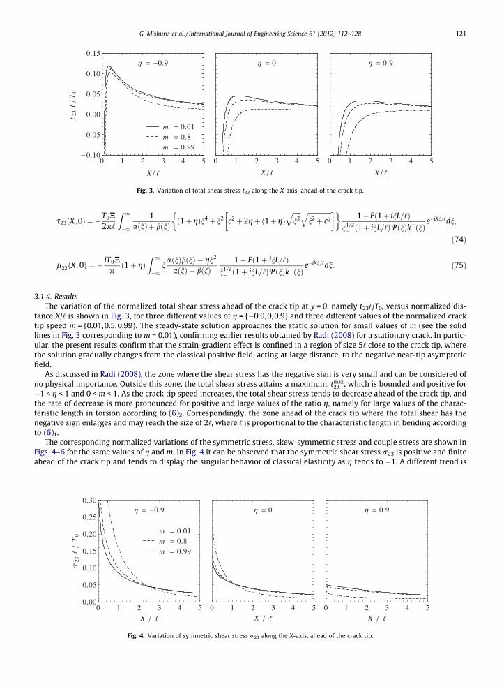
Fig. 3. Variation of total shear stress t23 along the X-axis, ahead of the crack tip.
G. Mishuris et al. / International Journal of Engineering Science 61 (2012) 112–128 121
s23ðX;0Þ ¼ �T0N2p‘
Z 1
�1
1aðnÞþ bðnÞ ð1þ gÞn4 þ n2 c2 þ 2gþ ð1þgÞ
ffiffiffiffiffin2
q ffiffiffiffiffiffiffiffiffiffiffiffiffiffiffin2 þ c2
q � 1� Fð1þ inL=‘Þ
n1=2� ð1þ inL=‘ÞWðnÞk�ðnÞ
e�iXn=‘dn;
ð74Þ
l22ðX;0Þ ¼ �iT0Npð1þ gÞ
Z 1
�1naðnÞbðnÞ � gn2
aðnÞ þ bðnÞ1� Fð1þ inL=‘Þ
n1=2� ð1þ inL=‘ÞWðnÞk�ðnÞ
e�iXn=‘dn: ð75Þ
3.1.4. ResultsThe variation of the normalized total shear stress ahead of the crack tip at y = 0, namely t23‘/T0, versus normalized dis-
tance X/‘ is shown in Fig. 3, for three different values of g = {�0.9,0,0.9} and three different values of the normalized cracktip speed m = {0.01,0.5,0.99}. The steady-state solution approaches the static solution for small values of m (see the solidlines in Fig. 3 corresponding to m = 0.01), confirming earlier results obtained by Radi (2008) for a stationary crack. In partic-ular, the present results confirm that the strain-gradient effect is confined in a region of size 5‘ close to the crack tip, wherethe solution gradually changes from the classical positive field, acting at large distance, to the negative near-tip asymptoticfield.
As discussed in Radi (2008), the zone where the shear stress has the negative sign is very small and can be considered ofno physical importance. Outside this zone, the total shear stress attains a maximum, tmax
23 , which is bounded and positive for�1 < g < 1 and 0 < m < 1. As the crack tip speed increases, the total shear stress tends to decrease ahead of the crack tip, andthe rate of decrease is more pronounced for positive and large values of the ratio g, namely for large values of the charac-teristic length in torsion according to (6)2. Correspondingly, the zone ahead of the crack tip where the total shear has thenegative sign enlarges and may reach the size of 2‘, where ‘ is proportional to the characteristic length in bending accordingto (6)1.
The corresponding normalized variations of the symmetric stress, skew-symmetric stress and couple stress are shown inFigs. 4–6 for the same values of g and m. In Fig. 4 it can be observed that the symmetric shear stress r23 is positive and finiteahead of the crack tip and tends to display the singular behavior of classical elasticity as g tends to �1. A different trend is
0.9
m 0.01m 0.8m 0.99
0 1 2 3 4 50.00
0.05
0.10
0.15
0.20
0.25
0.30
X
23T0
0
0 1 2 3 4 5X
0.9
0 1 2 3 4 5X
Fig. 4. Variation of symmetric shear stress r23 along the X-axis, ahead of the crack tip.
0.9
m 0.01m 0.8m 0.99
0 1 2 3 4 50.20
0.15
0.10
0.05
0.00
X
23T0
0
0 1 2 3 4 5
X
0.9
0 1 2 3 4 5
X
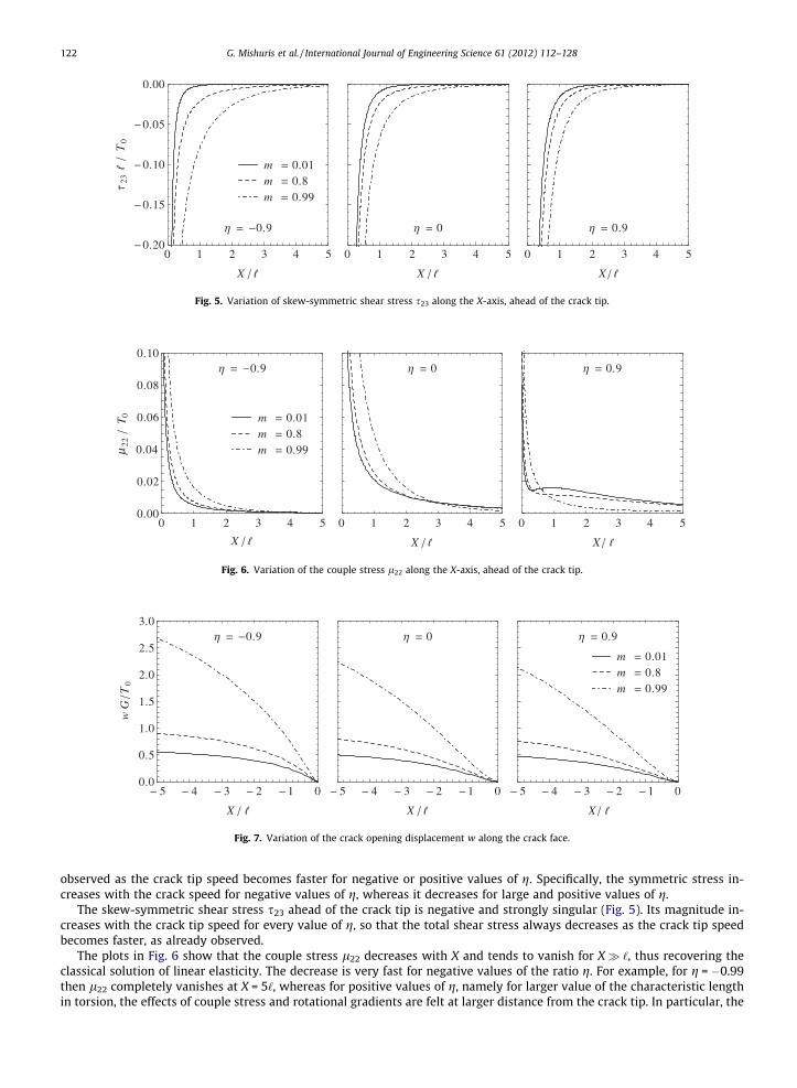
Fig. 5. Variation of skew-symmetric shear stress s23 along the X-axis, ahead of the crack tip.
0.9
m 0.01m 0.8m 0.99
0 1 2 3 4 50.00
0.02
0.04
0.06
0.08
0.10
X
22T 0
0
0 1 2 3 4 5
X
0.9
0 1 2 3 4 5
X
μ
Fig. 6. Variation of the couple stress l22 along the X-axis, ahead of the crack tip.
0.9
5 4 3 2 1 00.0
0.5
1.0
1.5
2.0
2.5
3.0
X
w G
T0
0
5 4 3 2 1 0
X
0.9
m 0.01m 0.8m 0.99
5 4 3 2 1 0
X
Fig. 7. Variation of the crack opening displacement w along the crack face.
122 G. Mishuris et al. / International Journal of Engineering Science 61 (2012) 112–128
observed as the crack tip speed becomes faster for negative or positive values of g. Specifically, the symmetric stress in-creases with the crack speed for negative values of g, whereas it decreases for large and positive values of g.
The skew-symmetric shear stress s23 ahead of the crack tip is negative and strongly singular (Fig. 5). Its magnitude in-creases with the crack tip speed for every value of g, so that the total shear stress always decreases as the crack tip speedbecomes faster, as already observed.
The plots in Fig. 6 show that the couple stress l22 decreases with X and tends to vanish for X� ‘, thus recovering theclassical solution of linear elasticity. The decrease is very fast for negative values of the ratio g. For example, for g = �0.99then l22 completely vanishes at X = 5‘, whereas for positive values of g, namely for larger value of the characteristic lengthin torsion, the effects of couple stress and rotational gradients are felt at larger distance from the crack tip. In particular, the
m 0.01m 0.8m 0.99
1.0 0.5 0.0 0.5 1.00.00
0.05
0.10
0.15
0.20t 23max
T0
1.0 0.5 0.0 0.5 1.00
1
2
3
4
5
Xmax
1.0 0.5 0.0 0.5 1.00
1
2
3
4
5
X0
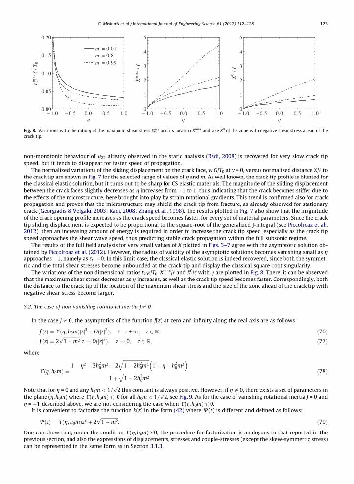
Fig. 8. Variations with the ratio g of the maximum shear stress tmax23 and its location Xmax and size X0 of the zone with negative shear stress ahead of the
crack tip.
G. Mishuris et al. / International Journal of Engineering Science 61 (2012) 112–128 123
non-monotonic behaviour of l22 already observed in the static analysis (Radi, 2008) is recovered for very slow crack tipspeed, but it tends to disappear for faster speed of propagation.
The normalized variations of the sliding displacement on the crack face, w G/T0 at y = 0, versus normalized distance X/‘ tothe crack tip are shown in Fig. 7 for the selected range of values of g and m. As well known, the crack tip profile is blunted forthe classical elastic solution, but it turns out to be sharp for CS elastic materials. The magnitude of the sliding displacementbetween the crack faces slightly decreases as g increases from �1 to 1, thus indicating that the crack becomes stiffer due tothe effects of the microstructure, here brought into play by strain rotational gradients. This trend is confirmed also for crackpropagation and proves that the microstructure may shield the crack tip from fracture, as already observed for stationarycrack (Georgiadis & Velgaki, 2003; Radi, 2008; Zhang et al., 1998). The results plotted in Fig. 7 also show that the magnitudeof the crack opening profile increases as the crack speed becomes faster, for every set of material parameters. Since the cracktip sliding displacement is expected to be proportional to the square-root of the generalized J-integral (see Piccolroaz et al.,2012), then an increasing amount of energy is required in order to increase the crack tip speed, especially as the crack tipspeed approaches the shear wave speed, thus predicting stable crack propagation within the full subsonic regime.
The results of the full field analysis for very small values of X plotted in Figs. 3–7 agree with the asymptotic solution ob-tained by Piccolroaz et al. (2012). However, the radius of validity of the asymptotic solutions becomes vanishing small as gapproaches �1, namely as ‘t ? 0. In this limit case, the classical elastic solution is indeed recovered, since both the symmet-ric and the total shear stresses become unbounded at the crack tip and display the classical square-root singularity.
The variations of the non dimensional ratios t23‘/T0, Xmax/‘ and X0/‘ with g are plotted in Fig. 8. There, it can be observedthat the maximum shear stress decreases as g increases, as well as the crack tip speed becomes faster. Correspondingly, boththe distance to the crack tip of the location of the maximum shear stress and the size of the zone ahead of the crack tip withnegative shear stress become larger.
3.2. The case of non-vanishing rotational inertia J – 0
In the case J – 0, the asymptotics of the function f(z) at zero and infinity along the real axis are as follows
f ðzÞ ¼ !ðg;h0mÞjzj3 þ Oðjzj2Þ; z! �1; z 2 R; ð76Þf ðzÞ ¼ 2
ffiffiffiffiffiffiffiffiffiffiffiffiffiffiffi1�m2p
jzj þ Oðjzj2Þ; z! 0; z 2 R; ð77Þ
where
!ðg;h0mÞ ¼1� g2 � 2h2
0m2 þ 2ffiffiffiffiffiffiffiffiffiffiffiffiffiffiffiffiffiffiffiffiffiffiffi1� 2h2
0m2q
1þ g� h20m2
� �1þ
ffiffiffiffiffiffiffiffiffiffiffiffiffiffiffiffiffiffiffiffiffiffiffi1� 2h2
0m2q : ð78Þ
Note that for g = 0 and any h0m < 1=ffiffiffi2p
this constant is always positive. However, if g – 0, there exists a set of parameters inthe plane (g,h0m) where !(g,h0m) 6 0 for all h0m < 1=
ffiffiffi2p
, see Fig. 9. As for the case of vanishing rotational inertia J = 0 andg = �1 described above, we are not considering the case when !(g,h0m) 6 0.
It is convenient to factorize the function k(z) in the form (42) where W(z) is different and defined as follows:
WðzÞ ¼ !ðg;h0mÞz2 þ 2ffiffiffiffiffiffiffiffiffiffiffiffiffiffiffi1�m2p
: ð79Þ
One can show that, under the condition !(g,h0m) > 0, the procedure for factorization is analogous to that reported in theprevious section, and also the expressions of displacements, stresses and couple-stresses (except the skew-symmetric stress)can be represented in the same form as in Section 3.1.3.
0
00
h0m 1 2
Superson ic regime
1.0 0.5 0.0 0.5 1.00.0
0.2
0.4
0.6
0.8
1.0
η
h0
m
Fig. 9. Region of ! > 0 in the g � h0m plane.
124 G. Mishuris et al. / International Journal of Engineering Science 61 (2012) 112–128
The Fourier transform of the skew-symmetric stress takes the form
�s23ðs;0Þ ¼ �T0N1
aþ ba2b2 þ ða2 þ b2 þ abÞgs2‘2 � ð1� 2h2
0m2Þs2‘2ðgs2‘2 � abÞn o 1� Fð1þ isLÞ
ðs‘Þ1=2� ð1þ isLÞWðslÞk�ðs‘Þ
; ð80Þ
which, after inversion, gives
s23ðX;0Þ
¼�T0N2p‘
Z 1
�1
1aðnÞþbðnÞ a2ðnÞb2ðnÞþða2ðnÞþb2ðnÞþaðnÞbðnÞÞgn2�ð1�2h2
0m2Þn2ðgn2�aðnÞbðnÞÞn o 1�Fð1þ inL=‘Þ
n1=2� ð1þ inL=‘ÞWðnÞk�ðnÞ
e�iXn=‘dn: ð81Þ
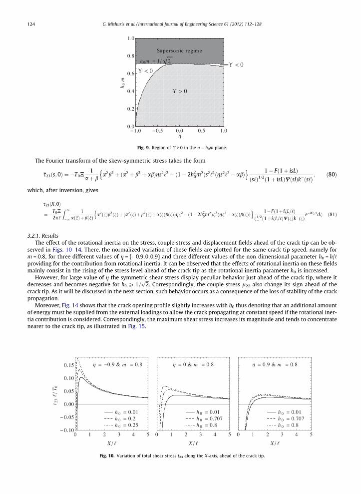
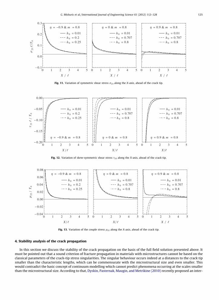
3.2.1. ResultsThe effect of the rotational inertia on the stress, couple stress and displacement fields ahead of the crack tip can be ob-
served in Figs. 10–14. There, the normalized variation of these fields are plotted for the same crack tip speed, namely form = 0.8, for three different values of g = {�0.9,0,0.9} and three different values of the non-dimensional parameter h0 = h/‘providing for the contribution from rotational inertia. It can be observed that the effects of rotational inertia on these fieldsmainly consist in the rising of the stress level ahead of the crack tip as the rotational inertia parameter h0 is increased.
However, for large value of g the symmetric shear stress display peculiar behavior just ahead of the crack tip, where itdecreases and becomes negative for h0 P 1=
ffiffiffi2p
. Correspondingly, the couple stress l22 also change its sign ahead of thecrack tip. As it will be discussed in the next section, such behavior occurs as a consequence of the loss of stability of the crackpropagation.
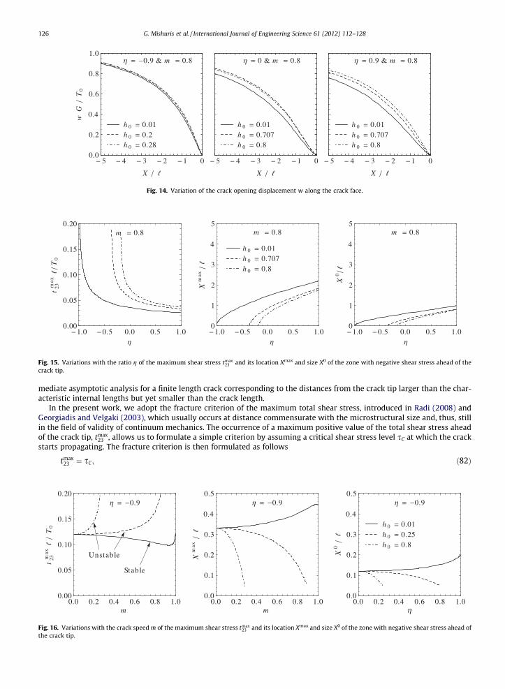
Moreover, Fig. 14 shows that the crack opening profile slightly increases with h0 thus denoting that an additional amountof energy must be supplied from the external loadings to allow the crack propagating at constant speed if the rotational iner-tia contribution is considered. Correspondingly, the maximum shear stress increases its magnitude and tends to concentratenearer to the crack tip, as illustrated in Fig. 15.
0.9 & m 0.8
h 0 0.01h 0 0.2h 0 0.25
0 1 2 3 4 50.10
0.05
0.00
0.05
0.10
0.15
X
t 23
T 0
0 & m 0.8
h 0 0.01h 0 0.707h 0 0.8
0 1 2 3 4 5
X
0.9 & m 0.8
h 0 0.01h 0 0.707h 0 0.8
0 1 2 3 4 5
X
Fig. 10. Variation of total shear stress t23 along the X-axis, ahead of the crack tip.
0.9 & m 0.8
h 0 0.01h 0 0.2h 0 0.25
0 1 2 3 4 50.20
0.15
0.10
0.05
0.00
X
23T0
0 & m 0.8
h 0 0.01h 0 0.707h 0 0.8
0 1 2 3 4 5
X
0.9 & m 0.8
h 0 0.01h 0 0.707h 0 0.8
0 1 2 3 4 5
X
Fig. 12. Variation of skew-symmetric shear stress s23 along the X-axis, ahead of the crack tip.
0.9 & m 0.8
h 0 0.01h 0 0.2h 0 0.25
0 1 2 3 4 50.04
0.02
0.00
0.02
0.04
0.06
0.08
X
22T0
0 & m 0.8
h 0 0.01h 0 0.707h 0 0.8
0 1 2 3 4 5
X
0.9 & m 0.8
h 0 0.01h 0 0.707h 0 0.8
0 1 2 3 4 5
X
Fig. 13. Variation of the couple stress l22 along the X-axis, ahead of the crack tip.
0.9 & m 0.8
h 0 0.01h 0 0.2h 0 0.25
0 1 2 3 4 50.1
0.0
0.1
0.2
0.3
X
23T0
0 & m 0.8
h 0 0.01h 0 0.707h 0 0.8
0 1 2 3 4 5
X
0.9 & m 0.8
h 0 0.01h 0 0.707h 0 0.8
0 1 2 3 4 5
X
Fig. 11. Variation of symmetric shear stress r23 along the X-axis, ahead of the crack tip.
G. Mishuris et al. / International Journal of Engineering Science 61 (2012) 112–128 125
4. Stability analysis of the crack propagation
In this section we discuss the stability of the crack propagation on the basis of the full field solution presented above. Itmust be pointed out that a sound criterion of fracture propagation in materials with microstructures cannot be based on theclassical parameters of the crack-tip stress singularities. The singular behaviour occurs indeed at a distances to the crack tipsmaller than the characteristic lengths, which can be commensurate with the microstructural size and even smaller. Thiswould contradict the basic concept of continuum modelling which cannot predict phenomena occurring at the scales smallerthan the microstructural size. According to that, Dyskin, Pasternak, Maugin, and Metrikine (2010) recently proposed an inter-
m 0.8
1.0 0.5 0.0 0.5 1.00.00
0.05
0.10
0.15
0.20
t 23max
T0
m 0.8
h 0 0.01h 0 0.707h 0 0.8
1.0 0.5 0.0 0.5 1.00
1
2
3
4
5
Xmax
m 0.8
1.0 0.5 0.0 0.5 1.00
1
2
3
4
5
X0
Fig. 15. Variations with the ratio g of the maximum shear stress tmax23 and its location Xmax and size X0 of the zone with negative shear stress ahead of the
crack tip.
0.9 & m 0.8
h 0 0.01h 0 0.2h 0 0.28
5 4 3 2 1 00.0
0.2
0.4
0.6
0.8
1.0
X
wG
T0
0 & m 0.8
h 0 0.01h 0 0.707h 0 0.8
5 4 3 2 1 0
X
0.9 & m 0.8
h 0 0.01h 0 0.707h 0 0.8
5 4 3 2 1 0
X
Fig. 14. Variation of the crack opening displacement w along the crack face.
126 G. Mishuris et al. / International Journal of Engineering Science 61 (2012) 112–128
mediate asymptotic analysis for a finite length crack corresponding to the distances from the crack tip larger than the char-acteristic internal lengths but yet smaller than the crack length.
In the present work, we adopt the fracture criterion of the maximum total shear stress, introduced in Radi (2008) andGeorgiadis and Velgaki (2003), which usually occurs at distance commensurate with the microstructural size and, thus, stillin the field of validity of continuum mechanics. The occurrence of a maximum positive value of the total shear stress aheadof the crack tip, tmax
23 , allows us to formulate a simple criterion by assuming a critical shear stress level sC at which the crackstarts propagating. The fracture criterion is then formulated as follows
t 23max
T0
Fig. 16.the cra
tmax23 ¼ sC ; ð82Þ
0.9
Stable
Unstable
0.0 0.2 0.4 0.6 0.8 1.00.00
0.05
0.10
0.15
0.20
m
0.9
0.0 0.2 0.4 0.6 0.8 1.00.0
0.1
0.2
0.3
0.4
0.5
m
Xmax
0.9
h 0 0.01h 0 0.25h 0 0.8
0.0 0.2 0.4 0.6 0.8 1.00.0
0.1
0.2
0.3
0.4
0.5
η
X0
Variations with the crack speed m of the maximum shear stress tmax23 and its location Xmax and size X0 of the zone with negative shear stress ahead of
ck tip.
0
Stable
Unstable
Init iallyunstable
0.0 0.2 0.4 0.6 0.8 1.00.00
0.02
0.04
0.06
0.08
m
t 23max
T0
0
0.0 0.2 0.4 0.6 0.8 1.00.0
0.5
1.0
1.5
2.0
2.5
3.0
m
Xmax
0
h 0 0.01h 0 0.6h 0 0.8
0.0 0.2 0.4 0.6 0.8 1.00.0
0.5
1.0
1.5
2.0
2.5
3.0
m
X0
Fig. 17. Variations with the crack speed m of the maximum shear stress tmax23 and its location Xmax and size X0 of the zone with negative shear stress ahead of
the crack tip.
0.9
Stable
Unstable
Init iallyunstable
0.0 0.2 0.4 0.6 0.8 1.00.00
0.01
0.02
0.03
0.04
0.05
m
t 23max
T0
0.9
0.0 0.2 0.4 0.6 0.8 1.00
1
2
3
4
5
m
Xmax
0.9
h 0 0.01h 0 0.707h 0 0.8
0.0 0.2 0.4 0.6 0.8 1.00
1
2
3
4
5
mX0
Fig. 18. Variations with the crack speed m of the maximum shear stress tmax23 and its location Xmax and size X0 of the zone with negative shear stress ahead of
the crack tip.
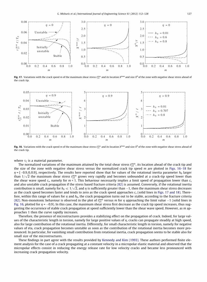
G. Mishuris et al. / International Journal of Engineering Science 61 (2012) 112–128 127
where sC is a material parameter.The normalized variations of the maximum attained by the total shear stress tmax
23 , its location ahead of the crack tip andthe size of the zone with negative shear stress versus the normalized crack tip speed m are plotted in Figs. 16–18 forg = {�0.9,0,0.9}, respectively. The results here reported show that for values of the rotational inertia parameter h0 largerthan 1=
ffiffiffi2p
the maximum shear stress tmax23 grows very rapidly and becomes unbounded at a crack-tip speed lower than
the shear wave speed cs, namely for m < 1. This behaviour necessarily implies a limit speed of propagation lower than cs
and also unstable crack propagation if the stress based fracture criteria (82) is assumed. Conversely, if the rotational inertiacontribution is small, namely for h0 1=
ffiffiffi2p
, and g is sufficiently greater than �1, then the maximum shear stress decreasesas the crack speed becomes faster and tends to zero as the crack speed approaches cs (solid lines in Figs. 17 and 18). There-fore, within this range of values for g and h0, the crack propagation turns out to be stable, according to the fracture criteria(82). Non-monotonic behaviour is observed in the plot of tmax
23 versus m for g approaching the limit value �1 (solid lines inFig. 16, plotted for g = �0.9). In this case, the maximum shear stress first decrease as the crack tip speed increases, thus sug-gesting the occurrence of stable crack propagation at speed sufficiently lower than the shear wave speed. However, as m ap-proaches 1 then the curve rapidly increases.
Therefore, the presence of microstructures provides a stabilizing effect on the propagation of crack. Indeed, for large val-ues of the characteristic length in torsion, namely for large positive values of g, cracks can propagate steadily at high speed,also for large contribution of the rotational inertia. Differently, for small characteristic length in torsion, namely for negativevalues of eta, crack propagation becomes unstable as soon as the contribution of the rotational inertia becomes more pro-nounced. In particular, for vanishing small contribution from rotational inertia, crack propagation seems to be stable also forsmall size of the microstructures.
These findings in part agree with the results provided by Kennedy and Kim (1993). These authors performed finite ele-ment analysis for the case of a crack propagating at a constant velocity in a micropolar elastic material and observed that themicropolar effects consist in reducing the energy release rate for low velocity cracks and became less pronounced withincreasing crack propagation velocity.
128 G. Mishuris et al. / International Journal of Engineering Science 61 (2012) 112–128
5. Conclusion
The full field solution for a semi-infinite crack steadily propagating in a couple stress elastic material and subject to anti-plane loading on the crack surfaces has been obtained by using Fourier transform and the Wiener–Hopf technique. The mate-rial microstructure is characterized by finite characteristic lengths in bending and torsion. The effect of rotational inertia isalso considered in the analysis.
The main conclusion is that couple stress elasticity, providing for material characteristic lengths, may provide a clearerpicture of the failure process near a rapidly moving crack tip than classical elasticity. The analysis based on classical theorydictates that the only way a Mode III crack can respond to additional influx of energy is by accelerating until it eventuallyoutruns the energy at the shear wave speed. However, phenomena such as the actual limiting crack speed under Mode IIIloading condition, which has been observed to be much lower than the shear wave speed as predicted by classical elastictheory, cannot at all be addressed by classical, linear elastic theories. Experimental investigations (Livne, Bouchbinder,Svetlizky, & Fineberg, 2010) also bring to light the influence of the fracture process on the limiting value. Since the processzone near the crack tip is strongly influenced by the microstructural parameters, such as the material characteristic lengthsand the rotational inertia, the maximum crack speed is also expected to be influenced by them. The fact that a fracture pro-cess zone has structure and dynamics associated with its evolution provides for the dependence on microstructural param-eters for the fracture energy and presents a possibility for explaining the lower observed limiting speeds and the definition ofthe range of stable crack propagation. Recently, advanced models of the fracture process have been proposed in literature,ranging from idealized atomistic and lattice models to phenomenological models to mechanism-based nucleation andgrowth models. While none of these models have advanced to the stage of providing quantitative explanation of the limitingspeed or for the dependence of the fracture energy on the crack speed, there are qualitative features of the present micro-polar model that appear promising.
Acknowledgements
G.M. acknowledges the support from European Union FP7 project under contract number PIAP-GA-2011–286110. The pa-per has been completed during the Marie Curie Fellowship of A.P. at Aberystwyth University supported by the EU FP7 projectunder contract number PIEF-GA-2009–252857. E.R. gratefully acknowledges financial support from the ‘‘Cassa di Risparmiodi Modena’’ in the framework of the International Research Project 2009–2010 ‘‘Modelling of crack propagation in complexmaterials’’.
References
Aifantis, E. C. (2011). On the gradient approach-relation to Eringen’s nonlocal theory. Int. J. Eng. Sci., 49, 1367–1377.Askes, H., & Aifantis, E. C. (2011). Gradient elasticity in statics and dynamics: An overview of formulations, length scale identification procedures, finite
element implementations and new results. Int. J. Solids Struct., 48, 1962–1990.Atkinson, C., & Leppington, F. G. (1977). The effect of couple stresses on the tip of a crack. Int. J. Solids Struct., 13, 1103–1122.Cosserat, E., & Cosserat, F. (1909). Theorie des Corps Deformables. Paris: Hermann et Fills.Dyskin, A. V., Pasternak, E., Maugin, G. A., & Metrikine, A. V. (2010). Cracks in Cosserat continuum-macroscopic modeling. In Mechanics of generalized
continua. Advances in mechanics and mathematics (Vol. 21, pp. 37–45). New York: Springer.Fleck, N. A., & Hutchinson, J. W. (2001). A reformulation of strain gradient plasticity. J. Mech. Phys. Solids, 49, 2245–2271.Fleck, N. A., Muller, G. M., Ashby, M. F., & Hutchinson, J. W. (1994). Strain gradient plasticity: Theory and experiment. Acta Metall. Mater., 42, 475–487.Freund, L. B. (1990). Dynamic Fracture Mechanics. Cambridge, UK: Cambridge University Press.Georgiadis, H. G., & Velgaki, E. G. (2003). High-frequency Rayleigh waves in materials with micro-structure and couple-stress effects. Int. J. Solids Struct., 40,
2501–2520.Han, S. Y., Narasimhan, M. N. L., & Kennedy, T. C. (1990). Dynamic propagation of a finite crack in a micropolar elastic solid. Acta Mech., 85, 179–191.Itou, S. (1981). The effect of couple-stresses on the stress concentration around a moving crack. Int. J. Math. Math. Sci., 4, 165–180.Jakata, K., & Every, A. G. (2008). Determination of the dispersive elastic constants of the cubic crystals Ge, Si, GaAs, and InSb. Phys. Rev. B, 77, 174301.Kennedy, T. C., & Kim, J. B. (1993). Dynamic analysis of cracks in micropolar elastic materials. Eng. Fract. Mech., 44, 207–216.Koiter, W. T. (1964). Couple-stresses in the theory of elasticity, I and II. Proc. Kon. Nederl. Akad. Wetensch (B), 67, 17–44.Lakes, R. S. (1986). Experimental microelasticity of two porous solids. Int. J. Solids Struct., 22, 55–63.Lakes, R. S. (1995). Experimental methods for study of Cosserat elastic solids and other generalized elastic continua. In H. Mühlhaus (Ed.), Continuum models
for materials with micro-structure (pp. 1–22). New York: John Wiley.Livne, A., Bouchbinder, E., Svetlizky, I., & Fineberg, J. (2010). The near-tip fields of fast cracks. Science, 327, 1359–1363.Lubarda, V. A., & Markenscoff, X. (2000). Conservation integrals in couple stress elasticity. J. Mech. Phys. Solids, 48, 553–564.Maranganti, R., & Sharma, P. (2007). A novel atomistic approach to determine strain-gradient elasticity constants: Tabulation and comparison for various
metals, semiconductors, silica, polymers and the (ir)relevance for nanotechnologies. J. Mech. Phys. Solids, 55, 1823–1852.Morozov, N. F. (1984). Mathematical problems of the theory of cracks. Moscow, Nauka.Morozov, N. F., & Nazarov, S. A. (1980). On the stress-strain state in a neighbourhood of a crack setting on a grain. Stud. Elasticity Plasticity, 13, 141–148.Nazarov, S. A., & Semenov, B. N. (1980). On the connection between stress intensity factors for a plane problem of the classical and couple-stress elasticity
theories. Stud. Elasticity Plasticity.Noble, B. (1958). Methods Based on the Wiener–Hopf Technique. Oxford, UK: Pergamon Press.Nowacki, W. (1985). Theory of asymmetric elasticity. Pergamon Press.Ottosen, N. S., Ristinmaa, M., & Ljung, C. (2000). Rayleigh waves obtained by the indeterminate couple-stress theory. Eur. J. Mech. A-Solids, 19, 929–947.Parhi, H. K., & Das, A. K. (1970). Note on couple-stresses in a halfplane produced by moving loads. Acta Mech., 9, 346–353.Piccolroaz, A., Mishuris, G., & Radi, E. (2012). Mode III interfacial crack in the presence of couple stress elastic materials. Eng. Fract. Mech., 80, 60–71.Radi, E. (2008). On the effects of characteristic lengths in bending and torsion on Mode III crack in couple stress elasticity. Int. J. Solids Struct., 45, 3033–3058.Zhang, L., Huang, Y., Chen, J. Y., & Hwang, K. C. (1998). The Mode III full-field solution in elastic materials with strain gradient effects. Int. J. Fract., 92,
325–348.