international journal of non-linear mechanics department of engineering science and mechanics, ......
TRANSCRIPT

Equilibria and instabilities of a Slinky: Discrete model
Douglas P. Holmes a,n, Andy D. Borumb, Billy F. Moore IIIa, Raymond H. Plaut c,David A. Dillard a
a Department of Engineering Science and Mechanics, Virginia Tech, Blacksburg, VA 24061, USAb Department of Aerospace Engineering, University of Illinois at Urbana-Champaign, Urbana, IL 61801, USAc Department of Civil and Environmental Engineering, Virginia Tech, Blacksburg, VA 24061, USA
a r t i c l e i n f o
Article history:Received 26 March 2014Received in revised form19 May 2014Accepted 26 May 2014Available online 10 June 2014
Keywords:Helical springsNon-linear deformationsStatic equilibriaDiscrete modelEnergy minimization
a b s t r a c t
The Slinky is a well-known example of a highly flexible helical spring, exhibiting large, geometricallynon-linear deformations from minimal applied forces. By considering it as a system of coils that act toresist axial, shearing, and rotational deformations, we develop a two-dimensional discretized model topredict the equilibrium configurations of a Slinky via the minimization of its potential energy. Carefulconsideration of the contact between coils enables this procedure to accurately describe the shape andstability of the Slinky under different modes of deformation. In addition, we provide simple geometricand material relations that describe a scaling of the general behavior of flexible, helical springs.
& 2014 Elsevier Ltd. All rights reserved.
1. Introduction
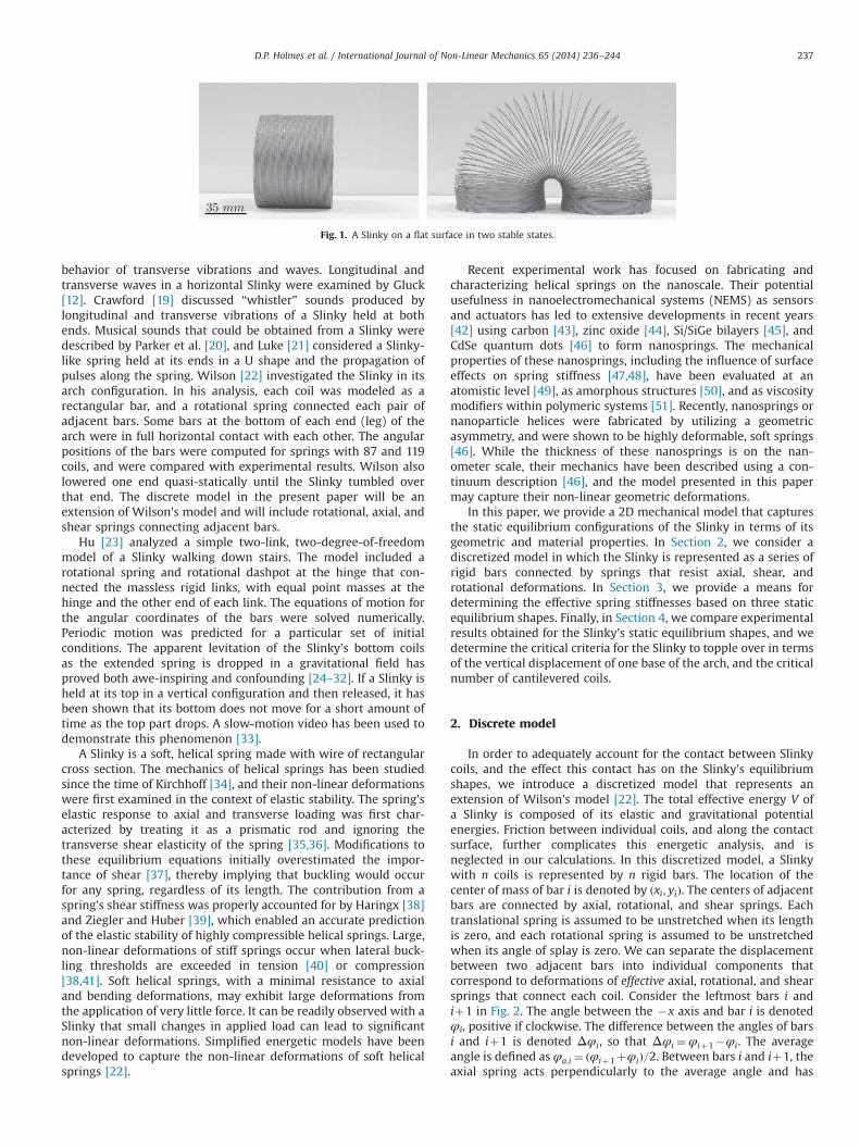
The floppy nature of a tumbling Slinky (Poof-Slinky, Inc.) hascaptivated children and adults alike for over half a century. Highlyflexible, the spring will walk down stairs, turn over in your hands,and – much to the chagrin of children everywhere – become easilyentangled and permanently deformed. The Slinky can be used asan educational tool for demonstrating standing waves, and astructural inspiration due to its ability to extend many timesbeyond its initial length without imparting plastic strain on thematerial. Engineers have scaled the iconic spring up to themacroscale as a pedestrian bridge [1], and down to the nanoscalefor use as conducting wires within flexible electronic devices [2,3],while animators have simulated its movements in a major motionpicture [4]. Yet, perhaps the most recognizable and remarkablefeatures of a Slinky are simply its ability to splay its helical coilsinto an arch (Fig. 1), and to tumble over itself down a steep incline.
A 1947 patent by Richard T. James for “Toy and process of use”[5] describes what became known as the Slinky, “a helical springtoy adapted to walk and oscillate.” The patent discusses thegeometrical features, such as a rectangular cross section with awidth-to-thickness ratio of 4:1, compressed height approximatelyequal to the diameter, almost no pretensioning but adjacent turns(coils) that touch each other in the absence of external forces, andthe ability to remain in an arch shape on a horizontal surface. In
the same year, Cunningham [6] performed some tests and analysisof a steel Slinky tumbling down steps and down an inclined plane.His steel Slinky had 78 turns, a length of 6.3 cm, and an outsidediameter of 7.3 cm. He examined the spring stiffness, the effects ofdifferent step heights and of inclinations of the plane, the timelength per tumble and the corresponding angular velocity, and thevelocity of longitudinal waves. He stated that the time period for astep height between 5 and 10 cm is almost independent of theheight and is about 0.5 s. Forty years later, he gave a furtherdescription of waves in a tumbling Slinky [7]. Longuet-Higgins [8]also studied a Slinky tumbling down stairs. His phosphor-bronzeSlinky had 89 turns, a length of 7.6 cm, and an outside diameter of6.4 cm. In his analysis, he imagined the Slinky as an elastic fluid,with one density at the end regions where coils touch and anotherfor the rest. His tests produced an average time of about 0.8 s perstep for a variety of step heights.
Heard and Newby [9] hung a Slinky-like spring vertically, heldat its top, with and without a mass attached at the bottom. Usingexperiments and analysis, they investigated the length, as didFrench [10], Sawicki [11], and Gluck [12], and they studied long-itudinal waves, as did Young [13], Bowen [14], and Gluck [12]. Inthe work by Bowen, the method of characteristics was utilized toobtain solutions of the wave equation (see also [15]), and aneffective mass of the Slinky was discussed, which was related tothe weight applied to an associated massless spring and yieldedthe same fundamental vibration period. Mak [16] defined aneffective mass with regard to the static elongation of the verticallysuspended Slinky. Blake and Smith [17] and Vandergrift et al. [18]suspended a Slinky horizontally by strings and investigated the
Contents lists available at ScienceDirect
journal homepage: www.elsevier.com/locate/nlm
International Journal of Non-Linear Mechanics
http://dx.doi.org/10.1016/j.ijnonlinmec.2014.05.0150020-7462/& 2014 Elsevier Ltd. All rights reserved.
n Corresponding author.E-mail address: [email protected] (D.P. Holmes).
International Journal of Non-Linear Mechanics 65 (2014) 236–244
behavior of transverse vibrations and waves. Longitudinal andtransverse waves in a horizontal Slinky were examined by Gluck[12]. Crawford [19] discussed “whistler” sounds produced bylongitudinal and transverse vibrations of a Slinky held at bothends. Musical sounds that could be obtained from a Slinky weredescribed by Parker et al. [20], and Luke [21] considered a Slinky-like spring held at its ends in a U shape and the propagation ofpulses along the spring. Wilson [22] investigated the Slinky in itsarch configuration. In his analysis, each coil was modeled as arectangular bar, and a rotational spring connected each pair ofadjacent bars. Some bars at the bottom of each end (leg) of thearch were in full horizontal contact with each other. The angularpositions of the bars were computed for springs with 87 and 119coils, and were compared with experimental results. Wilson alsolowered one end quasi-statically until the Slinky tumbled overthat end. The discrete model in the present paper will be anextension of Wilson's model and will include rotational, axial, andshear springs connecting adjacent bars.
Hu [23] analyzed a simple two-link, two-degree-of-freedommodel of a Slinky walking down stairs. The model included arotational spring and rotational dashpot at the hinge that con-nected the massless rigid links, with equal point masses at thehinge and the other end of each link. The equations of motion forthe angular coordinates of the bars were solved numerically.Periodic motion was predicted for a particular set of initialconditions. The apparent levitation of the Slinky's bottom coilsas the extended spring is dropped in a gravitational field hasproved both awe-inspiring and confounding [24–32]. If a Slinky isheld at its top in a vertical configuration and then released, it hasbeen shown that its bottom does not move for a short amount oftime as the top part drops. A slow-motion video has been used todemonstrate this phenomenon [33].
A Slinky is a soft, helical spring made with wire of rectangularcross section. The mechanics of helical springs has been studiedsince the time of Kirchhoff [34], and their non-linear deformationswere first examined in the context of elastic stability. The spring'selastic response to axial and transverse loading was first char-acterized by treating it as a prismatic rod and ignoring thetransverse shear elasticity of the spring [35,36]. Modifications tothese equilibrium equations initially overestimated the impor-tance of shear [37], thereby implying that buckling would occurfor any spring, regardless of its length. The contribution from aspring's shear stiffness was properly accounted for by Haringx [38]and Ziegler and Huber [39], which enabled an accurate predictionof the elastic stability of highly compressible helical springs. Large,non-linear deformations of stiff springs occur when lateral buck-ling thresholds are exceeded in tension [40] or compression[38,41]. Soft helical springs, with a minimal resistance to axialand bending deformations, may exhibit large deformations fromthe application of very little force. It can be readily observed with aSlinky that small changes in applied load can lead to significantnon-linear deformations. Simplified energetic models have beendeveloped to capture the non-linear deformations of soft helicalsprings [22].
Recent experimental work has focused on fabricating andcharacterizing helical springs on the nanoscale. Their potentialusefulness in nanoelectromechanical systems (NEMS) as sensorsand actuators has led to extensive developments in recent years[42] using carbon [43], zinc oxide [44], Si/SiGe bilayers [45], andCdSe quantum dots [46] to form nanosprings. The mechanicalproperties of these nanosprings, including the influence of surfaceeffects on spring stiffness [47,48], have been evaluated at anatomistic level [49], as amorphous structures [50], and as viscositymodifiers within polymeric systems [51]. Recently, nanosprings ornanoparticle helices were fabricated by utilizing a geometricasymmetry, and were shown to be highly deformable, soft springs[46]. While the thickness of these nanosprings is on the nan-ometer scale, their mechanics have been described using a con-tinuum description [46], and the model presented in this papermay capture their non-linear geometric deformations.
In this paper, we provide a 2D mechanical model that capturesthe static equilibrium configurations of the Slinky in terms of itsgeometric and material properties. In Section 2, we consider adiscretized model in which the Slinky is represented as a series ofrigid bars connected by springs that resist axial, shear, androtational deformations. In Section 3, we provide a means fordetermining the effective spring stiffnesses based on three staticequilibrium shapes. Finally, in Section 4, we compare experimentalresults obtained for the Slinky's static equilibrium shapes, and wedetermine the critical criteria for the Slinky to topple over in termsof the vertical displacement of one base of the arch, and the criticalnumber of cantilevered coils.
2. Discrete model
In order to adequately account for the contact between Slinkycoils, and the effect this contact has on the Slinky's equilibriumshapes, we introduce a discretized model that represents anextension of Wilson's model [22]. The total effective energy V ofa Slinky is composed of its elastic and gravitational potentialenergies. Friction between individual coils, and along the contactsurface, further complicates this energetic analysis, and isneglected in our calculations. In this discretized model, a Slinkywith n coils is represented by n rigid bars. The location of thecenter of mass of bar i is denoted by ðxi; yiÞ. The centers of adjacentbars are connected by axial, rotational, and shear springs. Eachtranslational spring is assumed to be unstretched when its lengthis zero, and each rotational spring is assumed to be unstretchedwhen its angle of splay is zero. We can separate the displacementbetween two adjacent bars into individual components thatcorrespond to deformations of effective axial, rotational, and shearsprings that connect each coil. Consider the leftmost bars i andiþ1 in Fig. 2. The angle between the �x axis and bar i is denotedφi, positive if clockwise. The difference between the angles of barsi and iþ1 is denoted Δφi, so that Δφi ¼φiþ1�φi. The averageangle is defined as φa;i ¼ ðφiþ1þφiÞ=2. Between bars i and iþ1, theaxial spring acts perpendicularly to the average angle and has
Fig. 1. A Slinky on a flat surface in two stable states.
D.P. Holmes et al. / International Journal of Non-Linear Mechanics 65 (2014) 236–244 237

extension Δξi, and the shear spring acts parallel to the averageangle and has extension Δzi (see Fig. 2). The differences inhorizontal and vertical coordinates x and y of the centers of massof bars i and iþ1 are denoted Δxi and Δyi, respectively. Then theaxial and shear deformations Δξi and Δzi can be determined fromthe geometric relationships
Δξi ¼Δxi sin ðφa;iÞþΔyi cos ðφa;iÞ; ð1aÞ
Δzi ¼Δxi cos ðφa;iÞ�Δyi sin ðφa;iÞ: ð1bÞ
The elastic energy of a Slinky is the sum of the strain energyassociated with axial, rotational, and shear deformations, withstiffnesses denoted by Ka, Kr, and Ks, respectively.
Boundary conditions can be prescribed on the variables xi, yi, orφi for some of the bars. For instance, for the splayed Slinky inFig. 1, the boundary conditions at the left end would bex1 ¼ y1 ¼φ1 ¼ 0, and at the right end they would be yn¼0,φn ¼ 1801, and xn ¼ 2Rþc0, where R is the radius of the Slinky(and half the length of each bar), and c0 is some positive constant.
Equilibrium shapes of this system of springs and masses can befound by minimizing V with respect to all unprescribed variables.The effective potential energy, including the gravitational potentialenergy (which acts in the �y direction), is written as
V ¼ 12Ka ∑
n�1
i ¼ 1Δξiþ
mgnp
Ka
� �2
þ12Ks ∑
n�1
i ¼ 1Δz2i þ
12Kr ∑
n�1
i ¼ 1Δφ2
i þmg ∑n
i ¼ 1yi;
ð2Þ
where m is the mass per coil, and g is the acceleration in the �ydirection due to gravity. We assume that pretensioning of theSlinky causes a constant precompression force Pp and, when theSlinky hangs vertically, causes np coils at the bottom to becompressed together [16]. The precompression force is approxi-mately equal to the weight of these compressed coils, i.e.,Pp¼mgnp. The axial term in Eq. (2) includes the deformationrequired to overcome Pp.
Accounting for the elastic potential energy of the springs alonewill only correspond to equilibrium shapes in the regime wherethere is no contact between Slinky coils. While we assume that thethree springs behave in a linearly elastic manner, the contactbetween coils adds a non-linearity that is not accounted for inEq. (2). Two types of contact can occur along the extended length ofthe spring. The first type, which we refer to as axial contact, occurswhen two adjacent coils are in contact around the entire circum-ference of the Slinky, as seen in the legs of the arch in Fig. 1. Thesecond type, which we refer to as rotational contact, occurs whentwo adjacent coils touch at only one point along the circumfer-ence, as seen in the coils above the legs of the arch in Fig. 1. Weaccount for this contact by introducing two penalty functions, Paand Pr, and defining the augmented total potential energy E by
E¼ VþPaþPr ð3Þ
To enforce the axial contact constraint, we must ensure that theaxial deformation is never smaller than the thickness, i.e. ΔξiZh.Pa adds a penalty when this constraint is violated, and has theform
Pa ¼ αa ∑n�1
i ¼ 1maxð0; �ðΔξi�hÞÞ2; ð4Þ
where αa controls the weight of the axial contact penalty function.To account for rotational contact, consider Fig. 2 with the lowerend of the left bar in contact with the next bar. In this configura-tion, Δξi ¼Δξmin where
Δξmin ¼ 2R sinΔφi
2þh cos
Δφi
2�Δzi tan
Δφi
2: ð5Þ
Therefore, for a given Δzi and Δφi, Δξmin is the minimumadmissible axial deformation. We can impose the constraint thatΔξi4Δξminð7Δφi;ΔziÞ with the penalty function Pr defined by
Pr ¼ αr ∑n�1
i ¼ 1maxð0; �ðΔξi�Δξminð7Δφi;ΔziÞÞÞ2; ð6Þ
where αr controls the weight of the rotational contact penaltyfunction. The local minima of E from Eq. (3) with respect to all
Fig. 2. A schematic showing the Slinky discretized into n bars, illustrating the axial,rotational, and shear springs between individual bars, and relative displacementsbetween adjacent bars.
Fig. 3. (A) An image of the Metal (L) Slinky hanging vertically suspended at its top. (B) An image of the same Slinky hanging horizontally in a gravitational field with its endcoils held at a fixed angle of 901, and separated by a distance L0. (C) An example of the experimental setup for the center loading and (D) edge loading on a single coil.(E) Force vs. displacement data for the center loaded and edge loaded coils. The slopes of these curves are used to determine Ka and Kr, respectively.
D.P. Holmes et al. / International Journal of Non-Linear Mechanics 65 (2014) 236–244238

unprescribed xi, yi, and φi yield predictions for stable equilibriumshapes of the Slinky.
3. Spring stiffnesses and equilibria
The augmented total potential energy is dependent on thestiffnesses of the springs. We will determine the relevant springstiffnesses based on simple mechanical equilibrium of the Slinkystructure in three specific configurations. The benefit of the staticequilibria method is its ease of implementation for flexible springslarge enough to have gravity be the dominant body force, whilesingle coil analysis via Castigliano's method provides a scalablemeans for determining the relevant spring stiffnesses [52].
The axial stiffness Ka can be determined by measuring theextended length of the vertically hanging Slinky suspended at itstop (Fig. 3A), and analyzing the discrete model. The compressedlength of the spring is L0 ¼ nh. The extended length of the hangingmodel is denoted L and includes the length nph of the np bars thatare compressed together at the bottom. We define N� n�np. Forthis vertical configuration we define the positions of the bars yi tobe positive if downward, with y1 ¼ 0 at the center of the bar that isheld at the top, and L¼ yNþ1þnph where yNþ1 gives the equili-brium position of the center of the top bar among the compressedbars at the bottom.
The governing equations are
Kað�yiþ1þ2yi�yi�1Þ ¼mg for i¼ 2;3;…;N; ð7aÞ
KaðyNþ1�yNÞ ¼ npmg�Pp ð7bÞ
The solution is
yi ¼ði�1Þ2Ka
2ðnpmg�PpÞþð2N� iÞmg� �
for i¼ 2;3;…;Nþ1 ð8Þ
Therefore, if Pp¼npmg, the extended length of the hanging Slinkymodel is
L¼ nphþNðN�1Þmg
2Kað9Þ
Conversely, the axial spring stiffness can be obtained from Eq. (9)as
Ka ¼NðN�1Þmg2ðL�nphÞ
ð10Þ
In the present notation, the result obtained in Mak [16] (seealso [24,30]) for a continuous spring is Ka ¼N2mg=½2ðL�nhÞ�.For the standard steel Slinky whose metrics are given inTable 1 denoted “Metal (L),” using n¼83, Eq. (10) results inKa¼64.0 N m�1. (Similar values were obtained by observing the
lowest natural frequency of axial vibration of the hanging Slinkyand comparing the measured value to the theoretical value [9].)
The shear stiffness can be determined by measuring themaximum deflection of the spring hanging horizontally in agravitational field, such that the first and the last coil are fixedwith zero displacement, y1 ¼ yn ¼ 0. To determine the shearstiffness, the end coils are held at a fixed angle of 901, andseparated by a distance L0 corresponding to the spring's com-pressed length (Fig. 3B). A very small initial separation beyond L0was imposed to reduce frictional effects. A force balance revealsthat the shear stiffness Ks to the left and right of the ith coil acts toresist gravity, such that Ksð�yiþ1þ2yi�yi�1Þ ¼mg, for i¼ 2;3;…;
n�1. The maximum deflection depends on whether the springcontains an even or odd number of coils, with ymax ¼nðn�2Þmgð8KsÞ�1 for an even number of coils, and ymax ¼ðn�1Þ2ðmgÞð8KsÞ�1 for an odd number. Therefore, the shearstiffness is given by (where j denotes a positive integer)
Ks ¼
mg8ymax
ðn�1Þ2 if n¼ 2jþ1;
mg8ymax
nðn�2Þ if n¼ 2j:
8>><>>: ð11Þ
For the Metal (L) Slinky in Table 1, with n¼83 and ymax ¼ 15:0 mm,this results in a shear stiffness Ks¼1370 N m�1. Table 1 describesthe Slinkys that were tested. The symbol L denotes long, XLdenotes extra long, M denotes medium length, and S denotesshort. Values reported in Table 1, beyond those already describedin the text, include coil thickness h, coil width b, and the mass of asingle coil m.
The axial stiffness Ka and rotational spring stiffness Kr can alsobe obtained from force (F) vs. displacement (δ) experiments on asingle coil loaded from the center by means of bails bent outwardfrom half coils (Fig. 3C) and the edge (Fig. 3D), respectively. Theslopes of the center-loaded and edge-loaded segments in Fig. 3Eare denoted Sc and Se, respectively. The curves are approximatelylinear, although they display a slight concavity, particularly withthe edge-loaded coil. A dashed line illustrates the deviation fromlinear behavior at moderate extension. Assuming that the center-loaded coil behaves like a linear spring, the force is simply theaxial spring stiffness times the vertical displacement. For the edge-loaded case, the total deflection at the edge, δ, is a superposition ofthe axial deformation, δa, and the bending deformation, δr, i.e.δ¼ δaþδr . If the angle of splay between the coils, θ, is small, thenthe moment about the center is M¼ FR¼ Krθ� KrδrR�1. There-fore, we can write δa ¼ FK �1
a and δr ¼ FR2K �1r . This leads to
δF¼ 1Se
¼ 1ScþR2
Kr; ð12Þ
and hence
Kr ¼ScSeR
2
Sc�Se: ð13Þ
We obtain values for the Metal (L) Slinky of Ka ¼ 69:9 N m�1 andKr ¼ 0:047 N m. The value of Ka obtained from the verticallyhanging Slinky is smaller than the Ka obtained from force–displacement experiments by 9%. This error may be attributed toa variation in pretension along the Slinky's length. The valuesobtained from the force–displacement experiments for the Metal(L) Slinky are used in the analysis below.
4. Experimental results
We first explored the various symmetric equilibrium shapesthat exist when the ends of a Slinky are held at a fixed angle withφ1 ¼ θ and φn ¼ π�θ, and their centers are separated by a finite
Table 1Slinky metrics.
Slinky n (#) L0(mm)
R(mm)
h(mm)
b(mm)
m (g) EA(N)
EI(10�6 N m2)
Metal (L) 82.75 54.82 34.18 0.67 2.74 2.49 0.046 3.153Metal (S) 79.50 34.45 20.16 0.49 1.87 0.61 0.023 3.241Plastic
(XL)45.50 148.13 78.50 2.88 7.40 14.44 0.099 582.2
Plastic (L) 41.00 77.58 47.47 1.39 7.77 3.02 0.019 47.16Plastic
(M1)34.00 60.27 37.31 1.78 3.18 1.59 0.027 23.71
Plastic(M2)
38.25 65.40 40.33 1.62 7.27 2.42 0.021 41.22
Plastic(M3)
37.00 61.42 38.26 1.66 3.41 1.65 0.022 19.41
Plastic (S) 31.50 46.97 31.21 0.93 6.18 1.20 0.016 11.27
D.P. Holmes et al. / International Journal of Non-Linear Mechanics 65 (2014) 236–244 239

distance (span) X ¼ xn�x1. We measured the downward deflection�yð0Þ of the center of the Slinky cross section at midspan as theends were separated horizontally. For comparison to the theore-tical models presented above, the simplest configuration to con-sider at first is when the ends are held at θ¼ 1801, as shown inFig. 4A. In this case, there is only contact between coils at theSlinky's center (if at all), and the effects of shear between coils areminimal. In Fig. 4B, we plot a graph of the vertical displacement ofthe Slinky's midpoint normalized by its radius R vs. the separationof the end coils normalized by the Slinky's unextended length L0.Even this fairly trivial configuration of a hanging Slinky leads tonon-linearities in its deflection as it is extended horizontally.These geometric non-linearities emerge from both the contactbetween the Slinky's coils and the non-linear terms due to thelarge slopes that appear in Eqs. (1a) and (1b). The discrete modelwithout consideration of contact between coils (Eq. (2)) does notoverestimate the central displacement for large values of X=L0. Itappears that maximal coil contact induces a significant non-linearity in the Slinky's central displacement. Fig. 4C shows acorresponding graph of the number of coils in contact as a
function of X=L0 for the same experiment. The contactless discretemodel is able to accurately predict yð0Þ=R when the number ofcoils in contact is approximately less than 11 (Fig. 4C-I.). As coilcontact increases, a small degree of non-linearity emerges in theexperimental data. This non-linearity is accurately captured whenthe discrete model allows for coil contact, but prevents theinterpenetration of coils, as presented in Eq. (3). We note thatadditional non-linearity is observed, and captured by our model,once the number of coils in contact reaches a fixed value, as shownby Fig. 4B-II. and C.
The lateral displacement experiment was repeated for differentangles θ, which ranged from θ¼ 01 to θ¼ 1801 in increments ofθ¼ 151. Images of a horizontally extended Metal (L) Slinky forthree different values of θ are shown in Fig. 5A. We measured themidpoint deflection as we varied the end-to-end displacementfrom X=L0 ¼ 1 to X=L0 ¼ 9 for each angle (Fig. 5B). Three distinctdeformation behaviors emerged. In the first case, which wasobserved for θ≲151, the Slinky's arch is initially concave (viz.concave down) with its midpoint above the origin, and thereis a continuous, reversible, non-linear decrease in the Slinky's
Fig. 4. (A) Images of the Metal (L) Slinky held by its ends at an angle of 1801 and separated by (i) X=L0 ¼ 2, (ii) X=L0 ¼ 5, and (iii) X=L0 ¼ 7. (B) A graph of the centraldisplacement of a Slinky yð0Þ normalized by its radius R as a function of end-to-end separation X normalized by the Slinky's unextended length L0. Along with theexperimental data, two theoretical curves are plotted – the discrete model with and without coil contact. (C) A graph of the number of coils in contact as a function of end-to-end separation.
Fig. 5. (A) Images of the Metal (L) Slinky separated by a fixed distance X ¼ 240 mm (X=L0 ¼ 4:38) and held by its ends at angles of (i) 01, (ii) 901, and (iii) 1801. (B) A graph ofthe normalized vertical midspan displacement vs. normalized horizontal span of a Slinky held at angles ranging from θ¼ 01 to θ¼ 1801. The solid lines correspond tonumerical results from the discrete model allowing for coil contact, and the dots denote experimental results.
D.P. Holmes et al. / International Journal of Non-Linear Mechanics 65 (2014) 236–244240

midpoint as the ends are separated horizontally. The significantgeometric non-linearities in this regime are due to both theamount of coil contact and the distribution of this contact alongthe Slinky's centerline. Fig. 5A-i shows coil contact at threedifferent locations along the centerline, occurring at the midspanand the ends as well as at both the lower and upper halves of thecoils. In the second case, when 301≲θ≲1201, there is a discontin-uous jump in the Slinky's midpoint as it reaches a deflection ofyð0Þ=R� �2, corresponding to an irreversible snap-throughbetween two Slinky configurations which resembles a saddle-node bifurcation. Preceding the bifurcation, the majority of coilcontact is concentrated around the Slinky's midpoint, and thisnon-uniform distribution of mass along the centerline is a factor inactivating the snap-through. In the third case, when θ41201, theSlinky hangs with an initially convex (viz. concave up) shape, andthere is very little deflection in the Slinky's midpoint as it ishorizontally extended. The subtle non-linearities in this regimewere described above for the specific case of θ¼ 1801. Theoreticalpredictions are plotted as solid lines along with the experimentalresults in Fig. 5B. These curves come from minimizing theaugmented total potential energy given by Eq. (3) using thestiffness values in Table 1. We note a very good qualitativeagreement between our experimental and theoretical results overall displacements and edge orientations. In particular, we note thatthe model captures the three deformation behaviors, including thesnap-through phenomenon.
The snap-through described above is the first example we willencounter of a large change in equilibrium shape for a smallrearrangement of the Slinky's position. Multiple bifurcationsbetween stable equilibrium shapes occur depending on thegeometrical variation in the Slinky's shape. For instance, considerhanging nH coils of a Slinky upward off the edge of a surfaceoriented at an angle θ, as shown in Fig. 6. The pretension withinthe Slinky and the shearing between coils will allow this config-uration to be stable up to a critical number of overhanging coils,n0. The discrete model is analyzed. The stability will be determinedfrom a balance of the moment acting on the cantilevered bars dueto their weight, and the moment that resists elongation from theshear stiffness and the compressive force due to pretensioningwithin the Slinky. The moment at the edge of the surface is thesum of these two contributions, and stability is lost when this total
moment is zero. The counterclockwise moment due to the weightof the coils is simply M1 ¼mg∑nH
i ¼ 1xi, where coil 1 is the furthestto the left, coil nH is the first overhanging one, the origin of thecoordinate system is at the edge of the surface, the x-axis ispositive to the left, and the y-axis is positive upward. Thissummation requires us to know the coordinates of the centers ofmass of the overhanging bars. With zi denoting the distance(positive if upward) along overhanging bar i from a leftwardextension of the surface (at angle θ with the x-axis) to the bar'scenter of mass, equilibrium along bar i yields Ksð�zi�1þ2zi�ziþ1Þ ¼ �mg cos θ for i¼ 2;3;…;nH where znH þ1 ¼ R, andKsðz1�z2Þ ¼ �mg cos θ. Then, from geometry, one can show thatthe locations of the centers of mass of the overhanging bars are
zi ¼ R�mg cos θ2Ks
ðnHþ iÞðnHþ1� iÞ ð14aÞ
xi ¼h cos θ
2ð1þ2nH�2iÞ�zi sin θ ð14bÞ
yi ¼h sin θ
2ð1þ2nH�2iÞþzi cos θ ð14cÞ
Since the pretension Pp¼mgnp acts through the center of bar nH,we can write the competing moment as M2 ¼ �mgnpznH , positiveif counterclockwise about the edge. Using Eqs. 14a–c, we find that
M1 ¼mg �nHR sin θþh2n2H cos θþmg
6KsnHð2n2
Hþ3nHþ1Þ sin θ cos θ� �
ð15aÞ
M2 ¼ �npmg R�mgKs
nH cos θ� �
ð15bÞ
The critical number of cantilevered coils is found by settingM1þM2 ¼ 0, which leads to a cubic equation for nH. The closestinteger greater than the lowest real solution nH yields the criticalvalue n0, and failure is expected (see lowest photograph in Fig. 6) ifn0 Slinky coils overhang the edge, according to the discrete model.In Fig. 6, we show a cantilevered Slinky, along with a plot of thecritical number of cantilevered coils n0 as a function of angle θ. Theequation for the critical number of cantilevered coils is plotted inFig. 6 for the Metal (L) Slinky, i.e. m¼ 0:00249 kg, h¼ 0:00067 m,np¼5, and R¼ 0:03418 m. This Slinky has a shear stiffness of
Fig. 6. Images of a Slinky cantilevered at an angle θ. We plot n0 vs. cantilever angle θ. The dashed curve is obtained from the discrete model (Eqs. (15a) and (15b)), and thedots represent experimental results.
D.P. Holmes et al. / International Journal of Non-Linear Mechanics 65 (2014) 236–244 241

Ks ¼ 1320 N m�1. There is a good agreement between our modeland experimental results denoted by dots.
With a strong correlation between our model using the Slinky'smechanical properties and the equilibrium shapes of the Slinky,we can generalize this model to a spring of any material or size bynon-dimensionalizing the relevant parameters. We normalize thetotal effective energy as V ¼ 2V=nmgR, and the axial deformationΔξi and vertical displacement yi by the coil thickness h, such thatΔξi ¼Δξi=h and yi ¼ yi=h. Due to the large separation of scalesbetween shear and either bending or axial deformation, in whichthe shear terms in Eq. (2) contribute much less than the otherterms, we neglect the shear stiffness and pretension, and write thedimensionless form of Eq. (2) as
V ¼ EAhnmgR
∑n�1
i ¼ 1Δξ2
i þEI
nmgRh∑n�1
i ¼ 1Δφ2
i þ2hnR
∑n
i ¼ 1yi; ð16Þ
where the barred quantities EA and EI represent effective axial andbending stiffnesses of the helical spring, respectively. Thesequantities are directly related to spring stiffnesses described inSection 3, with EA ¼ Kah and EI ¼ Krh. Eq. (16) provides severalnon-dimensional quantities that we can use to describe thevarious stability criteria of the Slinky. For instance, the prefactorto the first summation in Eq. (16) represents a balance betweenaxial extension and gravity, i.e. a spring with n� EAh=mgR willextend beyond L0 if held vertically from its top in a gravitationalfield. The second summation represents a balance between bend-ing stiffness and gravity, which provides a scaling of the numberof coils in a spring required for the structure to bend into astable arch,
nr � EImgRh
ð17Þ
We tested the validity of this scaling on a variety of flexible springsthat were initially stable as both arches and cylinders. Individualcoils, or fractions of coils, were removed until the Slinky wasunable to form a stable arch. We note that between the arch andthe cylinder configurations, a stable, intermediate state occurs inwhich one arch base rotates and only contacts the surface at apoint. We measured the critical number of coils nc required toform a stable arch with both bases in axial contact with ahorizontal surface (θ¼ 0) for a variety of commercially availableflexible springs (Fig. 7). Values of EA for each Slinky were obtained
as described in Section 3, while EI values were obtained usingCastigliano's method [52]. We plot nc vs. nr, given by Eq. (17), asthe horizontal axis. The dots denote experimental results corre-sponding to the Slinky examples listed in Table 1, and the dashedline represents nc¼nr. The scaling in Eq. (17) is in a goodagreement with the experimental results.
Once a Slinky is stable in the shape of an arch, stability loss canoccur if one end of the spring is lifted above a critical height,which we refer to as the step instability. Experimentally, weincrementally decreased yn relative to y1 in a quasi-static manner(where the y-axis is upward), and measured the critical displace-ment δc ¼ y1�yn as a function of the number of coils n (Fig. 8).This vertical displacement instability is similar to the onedescribed above for the number of coils required to stably forman arch. Decreasing the magnitude of yn by a height equivalent to acoil's thickness, i.e. δ¼ h, relative to y1 is analogous to removing asingle coil from the Slinky. Therefore, the effective number of coilsin the Slinky is simply neff ¼ n�δ=h. This effective coil number issimilar to the scaling in Eq. (17), however there will be axialresistance as one end of the Slinky is lowered in addition to theSlinky's rotational stiffness. By observing that all the coils in Fig. 8are in contact, we note that the Slinky satisfies the constraintdescribed by Eq. (5). If we neglect shear and assume that Δφi forall i are small, we have
Δξi ¼ 2R sinΔφi
2þh cos
Δφi
2� RΔφiþh ð18Þ
This approximation allows the non-dimensional potential energygiven in Eq. (16), leaving out terms that are constant or are linearin Δφi, to be rewritten as
V ¼ EAhnmgR
∑n�1
i ¼ 1
RΔφi
h
� �2
þ EInmgRh
∑n�1
i ¼ 1Δφ2
i þ2hnR
∑n
i ¼ 1yi
¼ EAR2þEInmgRh
!∑n�1
i ¼ 1Δφ2
i þ2hnR
∑n
i ¼ 1yi: ð19Þ
The prefactor of the first summation on the right-hand side ofthe equation essentially describes the dimensionless balancebetween axial and rotational stiffness and gravity when there isa contact between all the coils,
nar �EAR2þEImgRh
ð20Þ
Fig. 7. Images of various Slinkys in an arch shape. When the number of coils in the Slinky is below a critical value nc, it is no longer able to form an arch. We plot this criticalparameter vs. nr from Eq. (17), with dots denoting experimental results.
D.P. Holmes et al. / International Journal of Non-Linear Mechanics 65 (2014) 236–244242

We set the effective coil number neff equal to nar to solve for thecritical vertical displacement, and obtain
δc � nh�EAR2þEImgR
ð21Þ
We see in Fig. 8 that, for the Metal (L) Slinky, Eq. (21) capturesthe general trend of the data (denoted by dots). While contribu-tions from shear and pretension are much smaller than those fromaxial and rotational deformations in this configuration, the dis-crepancy with the data is likely due to these terms, which areneglected in the scaling presented in Eq. (20).
5. Conclusions
In this work, we present a discrete model to capture a Slinky'sstatic equilibria and unstable transitions. The model considers theSlinky's axial, shear, and rotational stiffnesses, and calculates theequilibrium shapes that result from a minimization of the struc-ture's total potential energy augmented by penalty functions toaccount for coil contact. We emphasize that modeling the contactbetween coils is crucial for describing its equilibrium shapes andquasi-static stability criteria. We determined the flexible spring'sstiffnesses by isolating specific static equilibrium shapes. Finally,we provide a general description of highly flexible helical springsby considering the non-dimensional potential energy of thespring, enabling the formulation of parameters that may describeand explain a Slinky's stability behavior under a variety of actions.The scaling argument for the slinkiness of a given spring should bevalid until the spring is dominated by forces other than gravity, e.g.electrostatics or magnetism. The focus of this work was onconfigurations for which the locus of the centers of the coils isplanar. Relaxing this planar configuration would be a naturalextension of the current work.
Acknowledgments
The authors acknowledge Poof–Slinky, Inc. for donating theinitial Slinkys used in this work, and Virginia Tech's Department ofEngineering Science and Mechanics for use of shared facilities. Thework of A.D. Borum was supported by the NSF-GRFP under Grantno. DGE-1144245.
References
[1] M. Schlaich, A. Goldack, M. Nier, Die mehrfeldrige Spannbandbrücke SlinkySprings to Fame in Oberhausen, Stahlbau 81 (2) (2012) 108–115.
[2] Y. Sun, W. Choi, H. Jiang, Y.Y. Huang, J.A. Rogers, Controlled buckling ofsemiconductor nanoribbons for stretchable electronics, Nat. Nanotechnol. 1(3) (2006) 201–207.
[3] F. Xu, W. Lu, Y. Zhu, Controlled 3D buckling of silicon nanowires for stretchableelectronics, ACS Nano 5 (1) (2011) 672–678.
[4] A. Lo, J. Chong, D. Ryu, Simulation-aided performance: behind the coils ofSlinky Dog in Toy Story 3, in: ACM SIGGRAPH ASIA 2010 Sketches Article no.49, 2010.
[5] R.A. James, Toy and process of use, U.S. Patent #2415012, January 28, 1947.[6] W.J. Cunningham, The physics of the tumbling spring, Am. J. Phys. 15 (4)
(1947) 348–352.[7] W.J. Cunningham, Slinky: the tumbling spring, Am. Sci. 75 (3) (1987) 289–290.[8] M.S. Longuet-Higgins, On Slinky: the dynamics of a loose, heavy spring, Math.
Proc. Camb. Philos. Soc. 50 (2) (1954) 347–351.[9] T.C. Heard, N.D. Newby, Behavior of a soft spring, Am. J. Phys. 45 (11) (1977)
1102–1106.[10] A.P. French, The suspended Slinky: a problem in static equilibrium, Phys.
Teach. 32 (4) (1994) 244–245.[11] M. Sawicki, Static elongation of a suspended Slinky, Phys. Teach. 40 (5) (2002)
276–278.[12] P. Gluck, A project on soft springs and the Slinky, Phys. Educ. 45 (2) (2010)
178–185.[13] R. Young, Longitudinal standing waves on a vertically suspended Slinky, Am. J.
Phys. 61 (4) (1993) 353–360.[14] J. M Bowen, Slinky oscillations and the notion of effective mass, Am. J. Phys. 50
(12) (1982) 1145–1148.[15] J.T. Cushing, The method of characteristics applied to the massive spring
problem, Am. J. Phys. 52 (10) (1984) 933–937.[16] S.Y. Mak, The static effectiveness mass of a slinky, Am. J. Phys. 55 (11) (1987)
994–997.[17] J. Blake, L.N. Smith, The Slinky as a model for transverse waves in a tenuous
plasma, Am. J. Phys. 47 (9) (1979) 807–808.[18] G. Vandergrift, T. Baker, J. DiGrazio, A. Dohne, A. Flori, R. Loomis, C. Steel,
D. Velat, Wave cutoff on a suspended slinky, Am. J. Phys. 57 (10) (1989)949–951.
[19] F.S. Crawford, Slinky whistlers, Am. J. Phys. 55 (2) (1987) 130–134.[20] J. Parker, H. Penttinen, S. Bilbao, J.S. Abel, Modeling methods for the highly
dispersive Slinky spring: a novel musical toy, in: Proceedings of the 13thInternational Conference on Digital Audio Effects (DAFx-10), 2010, pp. 1–4.
[21] J.C. Luke, The motion of a stretched string with zero relaxed length in agravitational field, Am. J. Phys. 60 (6) (1992) 529–532.
[22] J.F. Wilson, Energy thresholds for tumbling springs, Int. J. Non-Linear Mech. 36(8) (2001) 1179–1196.
[23] A.-P. Hu, A simple model of a Slinky walking down stairs, Am. J. Phys. 78 (1)(2010) 35–39.
[24] M.G. Calkin, Motion of a falling spring, Am. J. Phys. 61 (3) (1993) 261–264.[25] M. Gardner, A slinky problem, Phys. Teach. 38 (2) (2000) 78.[26] M. Graham, Analysis of Slinky levitation, Phys. Teach. 39 (2) (2001) 90.[27] S. Kolkowitz, The physics of a falling Slinky, ⟨http://large.stanford.edu/courses/
2007/ph210/kolkowitz1⟩, Accessed: February 2014, 2007.[28] J.M. Aguirregabiria, A. Hernández, M. Rivas, Falling elastic bars and springs,
Am. J. Phys. 75 (7) (2007) 583–587.[29] W.G. Unruh, The falling slinky, arXiv.org. (1110.4368), 2011, pp. 1–5.
Fig. 8. Images of Slinky losing stability as one edge is lowered below a critical displacement δc, and a plot of δc vs. the number of coils n.
D.P. Holmes et al. / International Journal of Non-Linear Mechanics 65 (2014) 236–244 243

[30] R.C. Cross, M.S. Wheatland, Modeling a falling slinky, Am. J. Phys. 80 (12)(2012) 1051–1060.
[31] H. Sakaguchi, Shock waves in falling coupled harmonic oscillators, J. Phys. Soc.Jpn. 82 (7) (2013) 073401.
[32] R.H. Plaut, A.D. Borum, D.P. Holmes, D.A. Dillard, Falling vertical chain ofoscillators, including collisions, damping, and pretensioning, under review.
[33] A. Shomsky, Slow motion slinky drop 1000 fps, YouTube, YouTube, December2011. Web. March 2014.
[34] I. Todhunter, K. Pearson, A History of the Theory of Elasticity and of theStrength of Materials, vol. 2, Part 2, Cambridge University Press, Cambridge,1893.
[35] E. Hurlbrink, Berechnung zylindrischer Druckfedern auf Sicherheit gegenseitliches Ausknicken, Z. Ver. Dtsch. Ing. 54 (3) (1910) 133–137.
[36] R. Grammel, Die Knickung von Schraubenfedern, Z. Angew. Math. Mech. 4 (5)(1924) 384–389.
[37] C.B. Biezeno, J.J. Koch, Knicking von Schraubenfedern, Z. Angew. Math. Mech. 5(3) (1925) 279–280.
[38] J.A. Haringx, On Highly Compressible Helical Springs and Rubber Rods, andTheir Application for Vibration-free Mountings, Philips Research Laboratories,1948.
[39] H. Ziegler, A. Huber, Zur Knickung der gedrückten und tordierten Schraubenfeder,Z. Angew. Math. Phys. 1 (3) (1950) 189–195.
[40] D.A. Kessler, Y. Rabin, Stretching instability of helical springs, Phys. Rev. Lett.90 (2) (2003) 024301.
[41] A.M. Wahl, Mechanical Springs, 2nd ed., McGraw-Hill, New York, 1963.
[42] B.A. Korgel, Nanosprings take shape, Science 309 (5741) (2005) 1683–1684.[43] M.A. Poggi, J.S. Boyles, L.A. Bottomley, A.W. McFarland, J.S. Colton, C.V. Nguyen,
R.M. Stevens, P.T. Lillehei, Measuring the compression of a carbon nanospring,Nano Lett. 4 (6) (2004) 1009–1016.
[44] P.X. Gao, Y. Ding, W. Mai, W.L. Hughes, C. Lao, Z.L. Wang, Conversion of zincoxide nanobelts into superlattice-structured nanohelices, Science 309 (5741)(2005) 1700–1704.
[45] S. Kim, W. Kim, M. Cho, Design of nanosprings using Si/SiGe bilayer thin film,Jpn. J. Appl. Phys. 50 (7) (2011) 070208.
[46] J.T. Pham, J. Lawrence, D.Y. Lee, G.M. Grason, T. Emrick, A.J. Crosby, Highlystretchable nanoparticle helices through geometric asymmetry and surfaceforces, Adv. Mater. 25 (46) (2013) 6703–6708.
[47] J.-S. Wang, Y.-H. Cui, X.-Q. Feng, G.-F. Wang, Q.-H. Qin, Surface effects on theelasticity of nanosprings, Europhys. Lett. 92 (1) (2010) 16002.
[48] D.-H. Wang, G.-F. Wang, Influence of surface energy on the stiffness ofnanosprings, Appl. Phys. Lett. 98 (8) (2011) 083112.
[49] I.-L. Chang, M.-S. Yeh, An atomistic study of nanosprings, J. Appl. Phys. 104 (2)(2008) 024305.
[50] A.F. da Fonseca, C.P. Malta, D.S. Galvao, Mechanical properties of amorphousnanosprings, Nanotechnology 17 (22) (2006) 5620–5626.
[51] J. Liu, Y.-L. Lu, M. Tian, F. Li, J. Shen, Y. Gao, L. Zhang, The interesting influenceof nanosprings on the viscoelasticity of elastomeric polymer materials,simulation and experiment, Adv. Funct. Mater. 23 (9) (2012) 1156–1163.
[52] A. Castigliano, Théorie de l’équilibre des systèmes élastiques et ses applica-tions, vol. 1, AF Negro, 1879.
D.P. Holmes et al. / International Journal of Non-Linear Mechanics 65 (2014) 236–244244