international journal of thermal sciences - lmms.xjtu.edu.cnlmms.xjtu.edu.cn/pdf/2016015.pdf ·...
TRANSCRIPT

lable at ScienceDirect
International Journal of Thermal Sciences 107 (2016) 39e55
Contents lists avai
International Journal of Thermal Sciences
journal homepage: www.elsevier .com/locate/ i j ts
Heat transfer enhancement by X-type lattice in ventilated brake disc
H.B. Yan a, b, Q.C. Zhang b, c, **, T.J. Lu b, c, *
a School of Energy and Power Engineering, Xi'an Jiaotong University, Xi'an 710049, PR Chinab MOE Key Laboratory for Multifunctional Materials and Structures, Xi'an Jiaotong University, Xi'an 710049, PR Chinac State Key Laboratory for Strength and Vibration of Mechanical Structures, Xi'an Jiaotong University, Xi'an 710049, PR China
a r t i c l e i n f o
Article history:Received 17 March 2015Received in revised form15 February 2016Accepted 31 March 2016Available online 7 April 2016
Keywords:Ventilated brake discRadial vaneX-type latticeRotating flowHeat transfer enhancement
* Corresponding author. MOE Key Laboratory for MStructures, Xi'an Jiaotong University, Xi'an 710049, PR** Corresponding author. MOE Key Laboratory for MStructures, Xi'an Jiaotong University, Xi'an 710049, PR
E-mail addresses: [email protected] (Q.Ccn (T.J. Lu).
http://dx.doi.org/10.1016/j.ijthermalsci.2016.03.0261290-0729/© 2016 Elsevier Masson SAS. All rights res
a b s t r a c t
We introduce an improved design of the X-type lattice cored ventilated brake disc proposed in a previousstudy. Several annular sector X-type lattice components are integrated into the ventilated channel.Detailed thermo-fluidic characteristics of this new brake disc are explored by experiments and numericalsimulations. Experimental results reveal that the new brake disc exhibits better thermal uniformity thanthe preliminary X-type brake disc, leading to approximately uniform reduction of rubbing surfacetemperature relative to a prevalent radial vane brake disc. Within the typical operating range of a pas-senger vehicle (i.e., 200e1000 RPM), the new brake disc provides 18e21% and 7e17% higher steady-stateoverall cooling capacity than the radial vane and preliminary X-type brake discs, respectively. Numericalresults reveal that replacement of radial vanes by the X-type lattice reduces pumping capacity byapproximately 40%, deteriorating therefore local heat transfer on the inner surface, the outer rim surface,the inner rim surface and the rubbing surface of the rubbing discs. However, the unique topology of theX-type lattice results in successive interruption and redevelopment of flow and thermal boundary layers,flow impingement on upstream surface of each ligament, and stronger flow mixing in conjunction withan enlarged core surface area. Hence, heat transfer on core surface is substantially improved, which actsas the dominant mechanism for enhanced overall cooling performance of the new brake disc.
© 2016 Elsevier Masson SAS. All rights reserved.
1. Introduction
Disc brakes as illustrated in Fig. 1 have been prevalently used incontemporary passenger vehicles. During braking, a pair of brakepads is hydraulically forced against a brake disc (BD) to establishbrake torque. Thus a large amount of kinetic and potential energy ofthe vehicle is transformed into thermal energy via sliding frictionbetween the brake disc and the pads. While heat conduction to thebrake pads is purposely minimized to prevent brake fluid vapor-ization [1], approximately 90% of frictional heat is transferred to thebrake disc [2]. During high-load braking such as repeated high-speed braking and extended downhill braking, frictional heatingcan substantially overheat the brake disc [3,4]. A multitude ofstudies have reported that such overheating can result in or
ultifunctional Materials andChina.ultifunctional Materials andChina.. Zhang), [email protected].
erved.
aggravate brake fade [5e7], increased wear of friction pair [8],brake disc coning and thermal fatigue cracking [9e13]. Further,thermal non-uniformity in the rubbing discs can results in non-uniform deformation of the brake disc and localized excessivewear of the friction pair [14]. The consequent circumferentialvariation of disc thickness in conjunctionwith the cyclicality natureof the mechanical braking load would aggravate brake judder (i.e.,forced vibration of steering wheel, brake pedal and vehicle floor)[14]. Therefore, sufficient and uniform cooling of the brake disc iscrucial to ensure brake reliability and comfort, especially for highperformance passenger vehicles.
To effectively cool the brake disc, ventilated brake discs con-sisting of two rubbing discs that sandwich various heat dissipationelements have been widely applied. Pumping action of theserotating core elements induces an internal cooling flow through theventilated channel, in addition to external flow driven by rotatingrubbing discs. Compared with a solid brake disc, substantiallyimproved cooling is achieved by additional internal forced con-vection [15].
Ever since the popular application of brake discs in the 1960s[16], considerable efforts have been devoted to improving the

Nomenclature
A surface area (m2)Aref reference surface area (m2)b1, b2 widths of an intersection point in Fig. 5(c) (m)C1, C2 coefficients defined in Eq. (9)h local heat transfer coefficient defined in Eq. (6) (W/
(m2K))he local effective heat transfer coefficient defined in Eq.
(4) (W/(m2K))Hc radial vane or X-type lattice core height (m)Hhb1, Hhb2 axial dimensions of a brake hub (m)k thermal conductivity of air (W/(mK))l length of an X-type lattice unit cell (m)Lv1, Lv2 lengths of long and short vanes (m)_m mass flow rate of cooling air (kg/s)N rotational speed of a brake disc (RPM)Nu local Nusselt number defined in Eq. (5)Nue local effective Nusselt number defined in Eq. (3)Nuoverall overall Nusselt number defined in Eq. (7)p static pressure (Pa)q” local heat flux (W/m2)Qt total power input (W)r radial coordinate (m)r1er3 fillet radii as shown in Fig. 5(d, e) (m)Re rotational Reynolds number defined in Eq. (2)Rhb1, Rhb2radial dimensions of a brake hub (m)Rri, Rro inner and outer radii of an inboard disc (m)Rv radial location of vanes (m)t time (s)tl thickness of an X-type lattice ligament (m)tr thickness of a rubbing disc (m)tv thickness of vanes (m)T wall temperature (�C)Ta ambient air temperature (�C)Tf fluid temperature (�C)
TInfrared temperature measured by the infrared camera duringthe calibration of infrared camera (�C)
TThermocouple temperature measured by the thermocoupleduring the calibration of infrared camera (�C)
V relative velocity magnitude (m/s)w width of an X-type lattice unit cell (m)wl width of an X-type lattice ligament (m)yþ dimensionless wall distancez axial coordinate (m)
Greek symbolsa, b included angles as shown in Fig. 5(d, e) (�)εc core porosity of a brake discε emissivity of a matt black painth contribution of separate mechanism to overall heat
transfer enhancement defined in Eq. (10)q azimuth coordinate (�)q0 geometrical periodic angle of a brake disc (�)m dynamic viscosity of air (Pa s)r density of air (kg/m3)rSA core surface area density (m2/m3)s StefaneBoltzmann constant (W/(m2 K4))u angular velocity magnitude (rad/s)U Vorticity magnitude (s�1)
Subscripts (lowercase) and abbreviations (capital)BD brake disccs, CS core surface of a brake discirs, IRS inner rim surface of an inboard discis, IS inner surface of an inboard discm area-averaged valueOA orientation A of an X-type lattice in Fig. 2OB orientation B of an X-type lattice in Fig. 2ors, ORS outer rim surface of an inboard discrs, RS rubbing surface of an inboard discRPM revolutions per minute
H.B. Yan et al. / International Journal of Thermal Sciences 107 (2016) 39e5540
cooling performance of ventilated brake discs bymainly optimizingthe cross-section and configuration of heat dissipation elements as
Fig. 1. Schematic illustration of a passenger vehicle disc brake.
presented in [17e25]. As a result, ventilated brake discs withvarious prismatic core elements such as vanes and pin-fins aredeveloped and commercially available [26].
Recently, based on thorough review and evaluation of previousstudies, we introduced a new concept of bi-directional ventilatedbrake disc incorporating a newly developed multifunctional peri-odic cellular material, i.e., the X-type lattice [27]. As the first step, aprototype ventilated brake disc with annular X-type lattice core asshown in Fig. 2 (i.e., the preliminary X-type brake disc) was fabri-cated and tested in [27]. This lattice corewas fabricated by cutting asingle layer of X-type lattice block into annular shape. For a givenrotational speed in the typical operating range of a passengervehicle (i.e., 200e1000 RPM), experimental results demonstratedthat this novel brake disc provides 1e14% higher overall coolingcapacity relative to a prevalent radial vane brake disc. However, thestructural anisotropy of the X-type lattice core as illustrated inFig. 2, especially along the circumferential direction, leads to cir-cumferentially anisotropic local heat transfer pattern on the rub-bing surface as indicated by the measured contour of Nusseltnumber in Fig. 2 [27]. Regions nearby orientation B (OB) of the X-type lattice core exhibits up to 30% higher overall heat transfer thanthat nearby orientation A (OA) [27].
The circumferentially anisotropic local heat transfer pattern asshown in Fig. 2 motivates the authors to propose a new design of
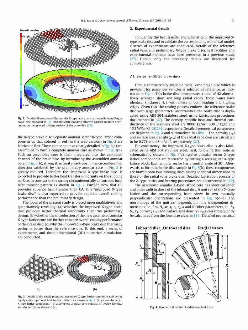
Fig. 2. Detailed illustration of the annular X-type lattice core in the preliminary X-typebrake disc proposed in [27] and the corresponding effective Nusselt number distri-bution on the inboard rubbing surface of the brake disc [27].
H.B. Yan et al. / International Journal of Thermal Sciences 107 (2016) 39e55 41
the X-type brake disc. Separate annular sector X-type lattice com-ponents as that colored in red (in the web version) in Fig. 2 arefabricated first. These components as clearly detailed in Fig. 3(a) areassembled to form a complete annular core as shown in Fig. 3(b).Such an assembled core is then integrated into the ventilatedchannel of the brake disc. By introducing the assembled annularcore in Fig. 3(b), strong structural anisotropy in the circumferentialdirection exhibited by the preliminary annular core in Fig. 2 isgreatly reduced. Therefore, the “improved X-type brake disc” isexpected to provide better heat transfer uniformity on the rubbingsurface, in contrast to the strong circumferentially anisotropic localheat transfer pattern as shown in Fig. 2. Further, now that OBprovides superior heat transfer than OA, this “improved X-typebrake disc” is also expected to provide superior overall coolingperformance than the preliminary design.
The focus of the present study is placed upon qualitatively andquantitatively revealing: (a) whether the improved X-type brakedisc provides better thermal uniformity than the preliminarydesign; (b) whether the introduction of the new assembled annularX-type lattice core can further enhance overall cooling performanceof the brake disc; (c) why the improved X-type brake disc thermallyperforms better than the reference one. To this end, a series ofexperiments and three-dimensional (3D) numerical simulationsare conducted.
Fig. 3. Details of the newly proposed assembled X-type lattice core motivated by thehighly anisotropic local heat transfer pattern as shown in Fig. 2: (a) an annular sectorX-type lattice component; (b) a complete annular core consists of twelve identicalannular sectors as shown in (a).
2. Experimental details
To quantify the heat transfer characteristics of the improved X-type brake disc and to validate the corresponding numerical model,a series of experiments are conducted. Details of the referenceradial vane and preliminary X-type brake discs, test facilities andexperimental methods have been presented in a previous study[27]. Herein, only the necessary details are described forcompleteness.
2.1. Tested ventilated brake discs
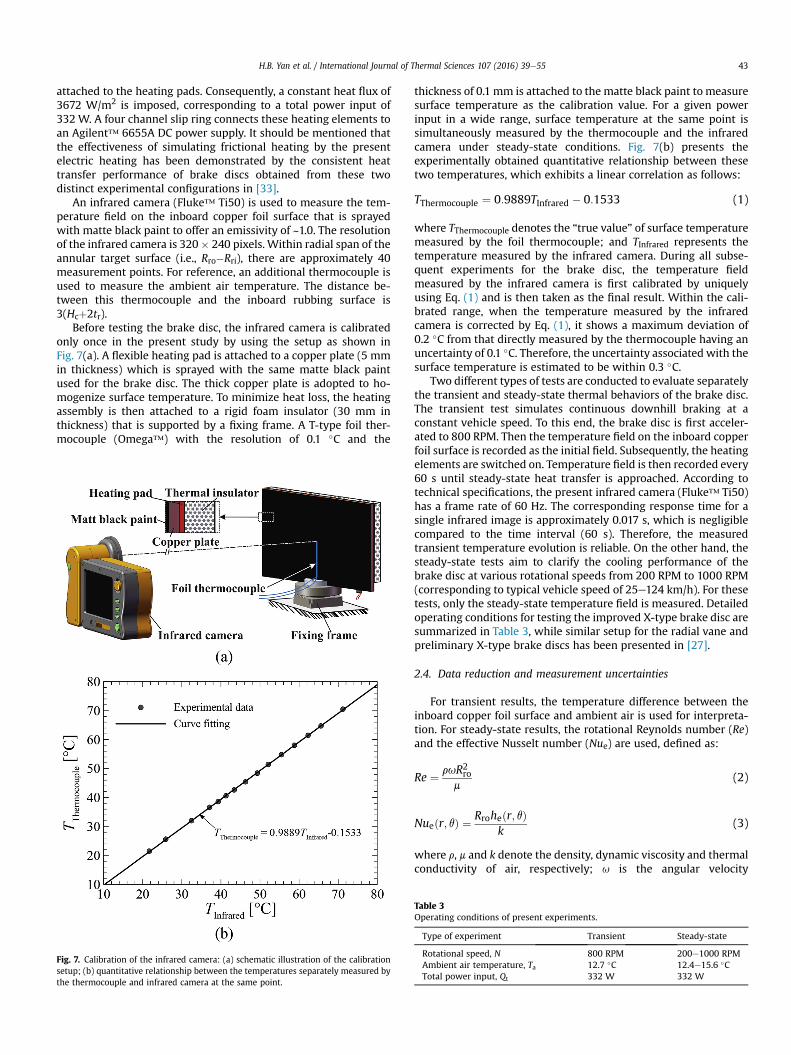
First, a commercially available radial vane brake disc which isprevalent for passenger vehicles is selected as reference, as illus-trated in Fig. 4. This brake disc incorporates a total of 42 alterna-tively arranged short and long radial vanes. These vanes haveidentical thickness (tv), with fillets at both leading and trailingedges. Given that the casting process endows the reference brakedisc with large geometrical uncertainties, the brake disc is dupli-cated using AISI 304 stainless steel, using fabrication proceduresdocumented in [27]. The density, specific heat and thermal con-ductivity of the stainless steel are 8000 kg/m3, 500 J/(kgK) and16.2W/(mK) [28,29], respectively. Detailed geometrical parametersare depicted in Fig. 4 and summarized in Table 1. The porosity (εc)and surface area density (rSA) of the radial vane core are calculatedto be 0.773 and 98 m2/m3, respectively [27].
For consistency, the improved X-type brake disc is also fabri-cated using AISI 304 stainless steel. First, following the route asschematically shown in Fig. 5(a), twelve annular sector X-typelattice components are fabricated by cutting a rectangular X-typelattice block. Each annular sector has a central angle of 30�. After-wards, to form the brake disc sample in Fig. 5(b), these componentsare brazed onto two rubbing discs having identical dimensions tothose of the radial vane brake disc. Detailed fabrication process ofthe X-type lattice and brazing procedures are documented in [30].
The assembled annular X-type lattice core has identical innerand outer radii to those of the inboard disc. A unit cell of the X-typelattice and the corresponding front views in two mutuallyperpendicular orientations are presented in Fig. 5(cee). Themorphology of the unit cell depends on nine independent di-mensions, i.e., l, w, Hc, wl, tl, r1, r2, a and b. Other parameters, i.e., b1,b2, r3, porosity (εc) and surface area density (rSA), can subsequentlybe calculated from the formulae given in [31]. Detailed geometrical
Fig. 4. Geometrical details of radial vane brake disc.

Table 1Geometrical parameters of radial vane brake disc.
Parameter Value Parameter Value
Hhb1 13.0 mm Rri 90.0 mmHhb2 21.0 mm Rro 150.0 mmHc 10.0 mm Rv 147.0 mmLv1 54.0 mm tr 9.0 mmLv2 46.0 mm tv 5.0 mmRhb1 74.0 mm εc 0.773Rhb2 82.0 mm rSA 98 m2/m3
Table 2Geometrical parameters of X-type lattice.
Parameter Value Parameter Value
b1 4.62 mm tl 0.91 mmb2 2.70 mm w 12.0 mmHc 9.66 mm wl 2.16 mml 12.0 mm a 50�
r1 0.30 mm b 42�
r2 4.30 mm εc 0.932r3 1.05 mm rSA 205 m2/m3
H.B. Yan et al. / International Journal of Thermal Sciences 107 (2016) 39e5542
parameters of the present X-type lattice are summarized in Table 2,which are identical to those presented in [27,31].
2.2. Test rig
The purposely designed rotating test rig is illustrated in Fig. 6. It
Fig. 5. Details of improved X-type brake disc: (a) an annular sector X-type latticecomponent; (b) as-fabricated brake disc; (c) unit cell of X-type lattice; (d) front view ofunit cell in OA; (e) front view of unit cell in OB.
contains a 3-phase AC motor and shafting mounted on a baseframe. The motor is connected to a shaft through a flexiblecoupling. The shaft rotates on bearings and is flanged at theopposite end to allow mounting of the brake disc sample. Anotherdismountable shaft supported by two additional bearings is boltedto the former shaft on one end. This is used to allow a cylindricalPerspex component (modeling the knuckle, with a radius of 0.4Rro)and a four-channel slip ring to be mounted. As highlighted in Fig. 6,the knuckle is flushmounted with the outboard disc. The rotationalspeed of the brake disc is controlled by an inverter connected to theAC motor and measured with a digital tachometer (from LutronElectronic Enterprise Co., Ltd., Taiwan) with a resolution of 0.1 RPM.
2.3. Heat transfer measurement
During actual braking, heat is generated by sliding friction be-tween the brake disc and pads. A majority of the heat is transferredto the brake disc and ultimately removed from the surfaces ofrubbing discs and heat dissipation elements. Since comparativeoverall cooling performance of the brake discs is of concern in thecurrent study, two identical annular heating pads having the sameinner and outer radii as those of the inboard disc are attached toboth rubbing discs by a thermally conductive double-sided tape, inorder to simulate frictional heating. The tape has a thickness of~0.1 mm and a thermal conductivity of ~1.5 W/(mK). Each heatingpad, thickness 0.2 mm, is consisted of etched Inconel heating wiressandwiched by two Kapton films. Each Kapton film has a thicknessof ~0.075 mm and a thermal conductivity of 0.12 W/(mK) [32]. Toremedy the non-uniformity of heat flux induced by the gaps be-tween heating wires, copper foils with a thickness of 0.06 mm are
Fig. 6. Three-dimensional illustration of the rotating test rig for heat transfermeasurement.
H.B. Yan et al. / International Journal of Thermal Sciences 107 (2016) 39e55 43
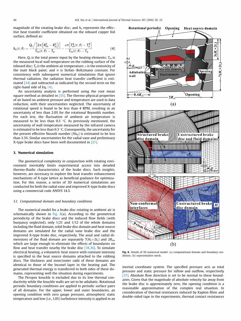
attached to the heating pads. Consequently, a constant heat flux of3672 W/m2 is imposed, corresponding to a total power input of332 W. A four channel slip ring connects these heating elements toan Agilent™ 6655A DC power supply. It should be mentioned thatthe effectiveness of simulating frictional heating by the presentelectric heating has been demonstrated by the consistent heattransfer performance of brake discs obtained from these twodistinct experimental configurations in [33].
An infrared camera (Fluke™ Ti50) is used to measure the tem-perature field on the inboard copper foil surface that is sprayedwith matte black paint to offer an emissivity of ~1.0. The resolutionof the infrared camera is 320� 240 pixels. Within radial span of theannular target surface (i.e., Rro�Rri), there are approximately 40measurement points. For reference, an additional thermocouple isused to measure the ambient air temperature. The distance be-tween this thermocouple and the inboard rubbing surface is3(Hcþ2tr).
Before testing the brake disc, the infrared camera is calibratedonly once in the present study by using the setup as shown inFig. 7(a). A flexible heating pad is attached to a copper plate (5 mmin thickness) which is sprayed with the same matte black paintused for the brake disc. The thick copper plate is adopted to ho-mogenize surface temperature. To minimize heat loss, the heatingassembly is then attached to a rigid foam insulator (30 mm inthickness) that is supported by a fixing frame. A T-type foil ther-mocouple (Omega™) with the resolution of 0.1 �C and the
Fig. 7. Calibration of the infrared camera: (a) schematic illustration of the calibrationsetup; (b) quantitative relationship between the temperatures separately measured bythe thermocouple and infrared camera at the same point.
thickness of 0.1 mm is attached to the matte black paint to measuresurface temperature as the calibration value. For a given powerinput in a wide range, surface temperature at the same point issimultaneously measured by the thermocouple and the infraredcamera under steady-state conditions. Fig. 7(b) presents theexperimentally obtained quantitative relationship between thesetwo temperatures, which exhibits a linear correlation as follows:
TThermocouple ¼ 0:9889TInfrared � 0:1533 (1)
where TThermocouple denotes the “true value” of surface temperaturemeasured by the foil thermocouple; and TInfrared represents thetemperature measured by the infrared camera. During all subse-quent experiments for the brake disc, the temperature fieldmeasured by the infrared camera is first calibrated by uniquelyusing Eq. (1) and is then taken as the final result. Within the cali-brated range, when the temperature measured by the infraredcamera is corrected by Eq. (1), it shows a maximum deviation of0.2 �C from that directly measured by the thermocouple having anuncertainty of 0.1 �C. Therefore, the uncertainty associated with thesurface temperature is estimated to be within 0.3 �C.
Two different types of tests are conducted to evaluate separatelythe transient and steady-state thermal behaviors of the brake disc.The transient test simulates continuous downhill braking at aconstant vehicle speed. To this end, the brake disc is first acceler-ated to 800 RPM. Then the temperature field on the inboard copperfoil surface is recorded as the initial field. Subsequently, the heatingelements are switched on. Temperature field is then recorded every60 s until steady-state heat transfer is approached. According totechnical specifications, the present infrared camera (Fluke™ Ti50)has a frame rate of 60 Hz. The corresponding response time for asingle infrared image is approximately 0.017 s, which is negligiblecompared to the time interval (60 s). Therefore, the measuredtransient temperature evolution is reliable. On the other hand, thesteady-state tests aim to clarify the cooling performance of thebrake disc at various rotational speeds from 200 RPM to 1000 RPM(corresponding to typical vehicle speed of 25e124 km/h). For thesetests, only the steady-state temperature field is measured. Detailedoperating conditions for testing the improved X-type brake disc aresummarized in Table 3, while similar setup for the radial vane andpreliminary X-type brake discs has been presented in [27].
2.4. Data reduction and measurement uncertainties
For transient results, the temperature difference between theinboard copper foil surface and ambient air is used for interpreta-tion. For steady-state results, the rotational Reynolds number (Re)and the effective Nusselt number (Nue) are used, defined as:
Re ¼ ruR2rom
(2)
Nueðr; qÞ ¼ Rroheðr; qÞk
(3)
where r, m and k denote the density, dynamic viscosity and thermalconductivity of air, respectively; u is the angular velocity
Table 3Operating conditions of present experiments.
Type of experiment Transient Steady-state
Rotational speed, N 800 RPM 200e1000 RPMAmbient air temperature, Ta 12.7 �C 12.4e15.6 �CTotal power input, Qt 332 W 332 W
H.B. Yan et al. / International Journal of Thermal Sciences 107 (2016) 39e5544
magnitude of the rotating brake disc; and he represents the effec-tive heat transfer coefficient obtained on the inboard copper foilsurface, defined as:
heðr; qÞ ¼Qt
.h2p
�R2ro � R2ri
�iTrsðr; qÞ � Ta
�εs
hT4rsðr; qÞ � T4a
iTrsðr; qÞ � Ta
(4)
Here, Qt is the total power input by the heating elements; Trs isthe measured local wall temperature on the rubbing surface of theinboard disc; Ta is the ambient air temperature; ε is the emissivity ofthe matt black paint; and s is StefaneBoltzmann constant. Forconsistency with subsequent numerical simulations that ignorethermal radiation, the radiation heat transfer coefficient is esti-mated [34] and subtracted as indicated by the second term on theright-hand side of Eq. (4).
An uncertainty analysis is performed using the root meansquare method as detailed in [35]. The thermo-physical propertiesof air based on ambient pressure and temperature are used in datareduction, with their uncertainties neglected. The uncertainty ofrotational speed is found to be less than 4 RPM, resulting in anuncertainty of less than 2.0% for the rotational Reynolds number.For each test, the fluctuation of ambient air temperature ismeasured to be less than 0.5 �C. As previously mentioned, theuncertainty of wall temperature measured by the infrared camerais estimated to be less than 0.3 �C. Consequently, the uncertainty forthe present effective Nusselt number (Nue) is estimated to be lessthan 3.3%. Similar uncertainties for the radial vane and preliminaryX-type brake discs have been well documented in [27].
3. Numerical simulation
The geometrical complexity in conjunction with rotating envi-ronment inevitably limits experimental access into detailedthermo-fluidic characteristics of the brake discs. Such insights,however, are necessary to explore the heat transfer enhancementmechanisms of X-type lattice as beneficial guidance for optimiza-tion. For this reason, a series of 3D numerical simulations areconducted for both the radial vane and improved X-type brake discsusing a commercial code ANSYS 14.5.
Fig. 8. Details of 3D numerical model: (a) computational domain and boundary con-ditions; (b) representative mesh.
3.1. Computational domain and boundary conditions
The numerical model for a brake disc rotating in ambient air isschematically shown in Fig. 8(a). According to the geometricalperiodicity of the brake discs and the induced flow fields (withbuoyancy neglected), only 1/21 and 1/12 of the whole domainsincluding the fluid domain, solid brake disc domain and heat sourcedomains are simulated for the radial vane brake disc and theimproved X-type brake disc, respectively. The axial and radial di-mensions of the fluid domain are separately 7(Hcþ2tr) and 2Rro,which are large enough to eliminate the effects of boundaries onflow and heat transfer nearby the brake disc [18,36]. To simulateelectrical heating, a volumetric heat source with constant intensityis specified in the heat source domains attached to the rubbingdiscs. The thickness and inner/outer radii of these domains areidentical to those of the Inconel layer in the heating pad. Thegenerated thermal energy is transferred to both sides of these do-mains, representing well the situation during experiments.
The Perspex knuckle is excluded due to its low thermal con-ductivity while the knuckle walls are set to be adiabatic. Rotationalperiodic boundary conditions are applied to periodic surface pairsof all domains. For the upper, lower and outer boundaries, anopening condition with zero gauge pressure, atmospheric statictemperature and low (i.e., 1.0%) turbulence intensity is applied in an
inertial coordinate system. The specified pressure acts as totalpressure and static pressure for inflow and outflow, respectively[37]. Absolute flow direction is set to be normal to these bound-aries. Given that the magnitude of absolute velocity far away fromthe brake disc is approximately zero, the opening condition is areasonable approximation of the complex real situation. Inconsideration of thermal resistances induced by Kapton films anddouble-sided tape in the experiments, thermal contact resistances

H.B. Yan et al. / International Journal of Thermal Sciences 107 (2016) 39e55 45
are added at interfaces between the heat source domains and otherdomains. For other interfaces between the solid and fluid domains,no-slip condition is adopted for fluid flow while conservativeinterface flux condition is used for heat transfer.
3.2. Numerical methods
A multi-block structured mesh incorporating fully hexahedralelements is generated by ANSYS ICEM CFD 14.5 in all domains of theradial vane brake disc. For the improved X-type brake disc, how-ever, a hybrid mesh as shown in Fig. 8(b) is adopted in consider-ation of its geometrical complexity. A multi-block structured meshis used to discretize the fluid domain outside the ventilated chan-nel, the brake hub and part of the rubbing discs. An unstructuredmesh with tetrahedral elements is generated in the remaining solidand fluid domains to resolve the complex geometry. Ten layers ofprism elements are generated near the solid walls of the unstruc-tured domain to resolve the boundary layers. Non-conformal in-terfaces are used to couple the structured and unstructureddomains. For both brake discs, the height of the first layer elementsadjacent to the solid walls is set to be ~0.01 mm, followed bysmooth transition to relatively coarse mesh away from the walls.One-to-one match of nodes is ensured for periodic faces.
Based on the finite volume method and the time marching al-gorithm, steady-state conjugate flow and heat transfer simulationsare performed using ANSYS CFX 14.5. The fluid (air) is assumed tobe incompressible and has constant thermo-physical propertiesbased on ambient pressure and temperature. The problem is solvedin a non-inertial reference frame that rotates at an angular velocityidentical to that of the brake disc [37]. In other words, the movingreference frame (MRF) method is adopted. The ANSYS CFX solvertakes the consequent Coriolis force and the centrifugal force in themomentum equation as source terms during iteration. To obtainturbulence viscosity, the shear stress transport (SST) turbulencemodel [38] incorporating a dimensionless wall distance (yþ) lessthan 1.0 is adopted. This model performed well for rotating flowssubjected to adverse pressure gradient as those associated withcentrifugal compressors [39] and ventilated brake discs [18,40]. Toreduce numerical error, the high resolution scheme is selected todiscretize advection terms in the governing equations.
3.3. Mesh independence test
Mesh sensitivity is examined for both brake discs at the highestrotational speed (i.e., 1000 RPM). For the radial vane brake disc,threemeshes with 2,125,347, 3,200,649 and 5,029,674 elements areconsidered. The area-averaged effective Nusselt numbers obtainedwith the last two meshes exhibit a discrepancy of 0.8%. For theimproved X-type brake disc, however, three finer meshes with12,512,533, 19,543,525 and 25,684,286 elements are used to cap-ture the largely separated internal flow induced by the X-typelattice. For this brake disc, the area-averaged effective Nusseltnumbers obtained with the last two meshes show a discrepancy of1.8%. Therefore, for effectiveness of computational cost, mesheswith 3,200,649 and 19,543,525 elements are used in subsequentsimulations for the radial vane and improved X-type brake discs,respectively.
4. Discussion of results
4.1. Improved thermal uniformity
As previously mentioned, thermal non-uniformity in the rub-bing discs would aggravate brake judder and hence should beexamined for the present brake disc. To this end, Fig. 9 presents the
measured distribution of local effective Nusselt number on theinboard rubbing surface at N ¼ 800 RPM. Details of the adoptedexperimental method are available in [27]. While the radial vanebrake disc exhibits a circumferentially isotropic heat transfer dis-tribution as shown in Fig. 9(a), a highly anisotropic local heattransfer pattern is observed for the preliminary X-type brake disc,as shown in Fig. 9(b). Two hot spots located separately at q ¼ 160�
and 340� show inferior heat transfer to that of the radial vane brakedisc, while regions nearby q ¼ 90� and 270� exhibit evidently su-perior heat transfer to that of the radial vane brake disc. However,the results of Fig. 9(c) demonstrate clearly that the introduction ofassembled annular X-type lattice core in the present study elimi-nates the hot spots, providing a circumferentially isotropic heattransfer pattern similar to that of the radial vane brake disc.
For quantitative comparison, representative profiles of effectiveNusselt number along circumferential lines I(aec) atr ¼ 0.5(Rri þ Rro) and radial lines II(bed) are extracted from Fig. 9and plotted in Fig. 10. Circumferentially, Fig. 10(a) reveals that thelocal Nusselt number for the improved X-type brake disc is onaverage ~4.0% lower than the peak Nusselt number at q ¼ 90� and270� exhibited by the preliminary X-type brake disc. Relative to theradial vane brake disc, an approximately uniform heat transferenhancement of ~24% is achieved. Radially, Fig. 10(b) also revealsthat local heat transfer for the improved X-type brake disc isslightly inferior to that at q ¼ 90� of the preliminary X-type brakedisc. Again, relative to the radial vane brake disc, local heat transferis enhanced by approximately 19%.
Profiles of effective Nusselt number from the present numericalsimulations are also plotted in Fig. 10, which show reasonableagreement with the experimental data. Circumferentially, themaximum deviations between the two data sets obtained numer-ically and experimentally are 6.1% and 3.7% for the radial vane andthe improved X-type brake discs, respectively. Within most of theradial span, the deviations are less than 9.0% and 5.0%, respectively.
4.2. Further enhanced overall cooling performance
Next, the brake discs are compared for overall cooling perfor-mance. As a result of varied braking mode, heat transfer associatedwith a brake disc can be either transient or steady-state. To char-acterize and compare the cooling performance of the brake discsexperiencing these distinctive heat transfer processes, extendeddownhill braking at a representative rotational speed of 800 RPM issimulated. Fig. 11(a) presents the measured transient evolution ofarea-averaged rubbing surface temperature for each type of brakedisc. When t < 200 s, all the brake discs operate at a similar tem-perature due to limited heat dissipation resulting from limitedtemperature difference between the brake disc and ambient air.When t > 200 s, the superiority of the improved X-type brake discrelative to both the radial vane and the preliminary X-type brakediscs becomes increasingly evident, peaking when the heat transferapproaches steady-state.
To compare the cooling performance of the considered brakediscs at selected rotational speeds, the area-averaged effectiveNusselt number (Nue, m) obtained from a series contours as those inFig. 9 is plotted in Fig. 11(b) as a function of the rotational Reynoldsnumber. The present experimental results reveal that the improvedX-type brake disc exhibits an 18e21% and 7%e17% higher steady-state overall cooling capacity than the radial vane and the pre-liminary X-type brake discs, respectively. Consequently, the oper-ating temperature of the brake disc can be further reduced byintroducing the present assembled annular X-type lattice core.
For validation of the numerical model, the Nusselt numbersobtained from numerical simulations are also presented inFig. 11(b). Both qualitatively and quantitatively, the present

Fig. 9. Measured distribution of effective Nusselt number on inboard rubbing surfaceat N ¼ 800 RPM: (a) radial vane brake disc; (b) preliminary X-type brake disc; (c)improved X-type brake disc.
θ [°]
Nu e
(I)
0 90 180 270 360600
800
1000
1200
1400Radial vane BD, I(a), ExperimentalPreliminary X-type BD, I(b), ExperimentalImproved X-type BD, I(c), ExperimentalRadial vane BD, I(a), NumericalImproved X-type BD, I(c), Numerical
r = 0.5(Rri+Rro)
(a)
r/Rro
Nu e
(II)
0.6 0.7 0.8 0.9 1600
800
1000
1200
1400
1600
1800 Radial vane BD, II(a), ExperimentalPreliminary X-type BD, II(b), ExperimentalPreliminary X-type BD, II(c), ExperimentalImproved X-type BD, II(d), ExperimentalRadial vane BD, II(a), NumericalImproved X-type BD, II(d), Numerical
r/Rro = 1r/Rro = Rri /Rro
(b) Fig. 10. Profiles of effective Nusselt number along (a) circumferential lines I(aec) and(b) radial lines II(aed) depicted in Fig. 9 at N ¼ 800 RPM.
H.B. Yan et al. / International Journal of Thermal Sciences 107 (2016) 39e5546
numerical results show reasonable agreement with thosemeasured experimentally, exhibiting a maximum deviation of 9.0%
and 9.5% at N ¼ 200 RPM for the radial vane and improved X-typebrake discs, respectively. The numerical results reveal that theimproved X-type brake disc provides 16%e18% higher Nusseltnumber than the radial vane brake disc, which is close to thatdemonstrated by the experimental data.
4.3. Heat transfer enhancement mechanisms
In view of the results shown in Fig. 11, it is important to un-derstand the underlying heat transfer enhancement mechanismsby the X-type lattice relative to the radial vane brake disc, asbeneficial guidance to further improve this new brake disc. To thisend, detailed fluid flow and heat transfer characteristics areexplored by using numerical simulations. Where possible, the re-sults presented below are for the inboard disc at a representativerotational speed of 800 RPM, analyzed in a non-inertial referenceframe rotating at an angular velocity identical to that of the brakedisc. It has been established that similar characteristics areobserved for the outboard disc and at other rotational speeds.
4.3.1. Flow and temperature fieldsAs basis of subsequent analysis, Fig. 12 first compares the
pumping capacity of the brake discs, i.e., mass flow rate of air ( _m)

t [s]
T rs,
m-T
a[°
C]
0 1000 2000 30000
5
10
15
20
25
30
Radial vane BD, ExperimentalPreliminary X-type BD, ExperimentalImproved X-type BD, Experimental
t = 200 s t = 3600 s
(a)
Re
Nu e
,m
50000 100000 150000
500
1000
1500
2000 Radial vane BD, ExperimentalPreliminary X-type BD, ExperimentalImproved X-type BD, ExperimentalRadial vane BD, NumericalImproved X-type BD, Numerical
N = 1000 RPM
N = 200 RPM
(b) Fig. 11. Comparison of overall cooling performance: (a) evolution of area-averagedtemperature on inboard rubbing surface at N ¼ 800 RPM; (b) variation of area-averaged effective Nusselt number with rotational Reynolds number.
N [RPM]
m[k
g/s]
200 400 600 800 1000
0.01
0.02
0.03
0.04
0.05
0.06
0.07Radial vane BD, NumericalImproved X-type BD, Numerical
.
N = 1000 RPM
N = 200 RPM
Fig. 12. Comparison of pumping capacity plotted as a function of rotational speed.
Fig. 13. Comparison of external flow as indicated by surface streamlines and velocitymagnitude distribution on an r-z plane at q ¼ 0�: (a) radial vane brake disc; (b)improved X-type brake disc.
H.B. Yan et al. / International Journal of Thermal Sciences 107 (2016) 39e55 47
sucked into the ventilated channel. For both brake discs, it is seenthat the pumping capacity linearly increases with increasing rota-tional speed, consistent with previous numerical and experimentalstudies [36,41e44]. Within the simulated range, the improved X-type brake disc exhibits an approximately 40% lower pumping ca-pacity than that of the radial vane brake disc.
With the aid of streamlines, velocity contours, static pressurecontours, vorticity contours and temperature contours, Figs. 13e18present comparisons of flow and temperature fields between thebrake discs. These thermo-fluidic patterns directly affect local heattransfer patterns on the brake disc surface.
Fig. 13 highlights the fluid flow behavior outside the ventilatedchannel, as indicated by surface streamlines and velocity magni-tude contours on a representative r-z plane. When both brake discsstart to rotate, the originally stationary air in the ventilated channelis driven radially outwards by centrifugal force, which lowers staticpressure at the ventilated channel inlet as evidenced by the pres-sure contours in Fig. 15. Consequently, cooling air continuouslyenters the ventilated channel due to positive pressure gradientfrom ambient to ventilated channel inlet (see Fig. 15) [45]. Suchinflow separates nearby inner rim surface (IRS) of the inboard disc,leading to a torus vortex adjacent to the cylindrical IRS. The in-tensity of this vortex is governed by pumping capacity, i.e., drivingpressure gradient as shown in Fig. 15. Higher pressure gradient due
to higher pumping capacity of the radial vane brake disc is expectedto result in a stronger torus vortex compared to the improved X-type brake disc. Due to shear effect of the jet-like outflow from theventilated channel, local static pressure at the ventilated channeloutlet is diminished as shown in Fig. 15. The corresponding positive

Fig. 14. Comparison of internal flow as indicated by surface streamlines and velocitymagnitude distribution on an r�q plane at z/Hc ¼ 0.5: (a) radial vane brake disc; (b)improved X-type brake disc. Fig. 15. Comparison of pressure distributions on representative r-z plane at q ¼ 0� and
r�q plane at z/Hc ¼ 0.5: (a) radial vane brake disc; (b) improved X-type brake disc.
H.B. Yan et al. / International Journal of Thermal Sciences 107 (2016) 39e5548
pressure gradient from outer edges of the rubbing discs to the coreof the jet-like flow drives cooling air to the outer rim surface (ORS)of the rubbing discs. Again, higher pressure gradient as shown inFig. 15 due to higher pumping capacity of the radial vane brake discleads to more rapid update of fluid nearby ORS compared to theimproved X-type brake disc. Similarly, the external flow over rub-bing surface (RS) is in general driven radially outwards by therotating disc. However, such external flow adjacent to IRS and ORSis accelerated by local pressure gradient as shown in Fig. 15. Due tolower pressure gradient, local flow velocity nearby inner and outeredges of the rubbing disc for the improved X-type brake disc islower than that for the radial vane brake disc, as revealed by ve-locity contours.
Fig. 14 details the fluid flow characteristics inside the ventilatedchannel, as indicated by surface streamlines and velocity magni-tude contours on a representative r�q plane. For the radial vanedisc, the smooth high-velocity flow nearby the pressure sides of thevanes and the low-velocity separated flow nearby the suction sides
of the vanes dominate the internal flow: detailed mechanisms arereferred to [45]. Flow and the corresponding thermal boundarylayers on the pressure sides initiate from the stagnation regions atthe leading edges of the vanes as evidenced by local peaks of staticpressure in Fig. 15, which then continuously develop till the trailingedges. For the improved X-type brake disc, however, the flow fromthe ventilated channel inlet is successively interrupted by latticeligaments. The flow first impinges on each ligament as revealed bythe local peaks of static pressure in Fig. 15 and then develops on theupstream surface of the ligament within a short distance, followedby separation nearby the downstream surface of the ligament. Incontrast to the relatively smooth flow (especially nearby the pres-sure sides), fluid entering the ventilated channel of the improved X-type brake disc follows a fairly tortuous route. At a given radiallocation, the flow velocity for the improved X-type disc is generallylower than that of the radial vane disc due to reduced pumpingcapacity in conjunction with higher core porosity as revealed by
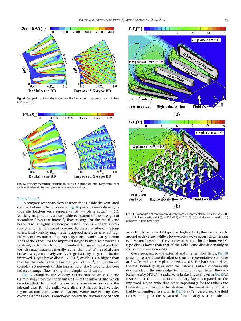
Fig. 16. Comparison of vorticity magnitude distributions on a representative r�q planeat z/Hc ¼ 0.5.
Fig. 17. Velocity magnitude distribution on an r�q plane 0.1 mm away from innersurface of inboard disc: comparison between brake discs.
Fig. 18. Comparison of temperature distributions on representative r-z plane at q ¼ 0�
and r�q plane at z/Hc ¼ 0.5 (Qt ¼ 332 W, Ta ¼ 12.7 �C): (a) radial vane brake disc; (b)improved X-type brake disc.
H.B. Yan et al. / International Journal of Thermal Sciences 107 (2016) 39e55 49
Tables 1 and 2To compare secondary flow characteristics inside the ventilated
channel between the brake discs, Fig. 16 presents vorticity magni-tude distributions on a representative r�q plane at z/Hc ¼ 0.5.Vorticity magnitude is a reasonable evaluation of the strength ofsecondary flows that intensify flow mixing. For the radial vanebrake disc, a highly anisotropic distribution is evident. Corre-sponding to the high speed flow nearby pressure sides of the longvanes, local vorticity magnitude is approximately zero, which sig-nifies poor flowmixing. High vorticity is observable nearby suctionsides of the vanes. For the improved X-type brake disc, however, arelatively uniform distribution is evident. At a given radial position,vorticity magnitude is generally higher than that of the radial vanebrake disc. Quantitatively, area-averaged voticity magnitude for theimproved X-type brake disc is 3203 s�1, which is 33% higher thanthat for the radial vane brake disc (i.e., 2413 s�1). In conclusion,complex 3D network of thin ligaments of the X-type lattice coreinduces stronger flow mixing than simple radial vanes.
Fig. 17 compares the velocity distribution on an r�q plane0.1 mm away from the inner surface (IS) of the inboard disc, whichdirectly affects local heat transfer pattern on inner surface of theinboard disc. For the radial vane disc, a U-shaped high-velocityregion around each vane is evident, while low-velocity flowcovering a small area is observable nearby the suction side of each
vane. For the improved X-type disc, high-velocity flow is observablearound each vertex, while a low-velocity wake occurs downstreameach vertex. In general, the velocity magnitude for the improved X-type disc is lower than that of the radial vane disc due mainly toreduced pumping capacity.
Corresponding to the external and internal flow fields, Fig. 18presents temperature distributions on a representative r-z planeat q ¼ 0� and an r�q plane at z/Hc ¼ 0.5. For both brake discs,thermal boundary layer over the rubbing surface continuouslydevelops from the inner edge to the outer edge. Higher flow ve-locity nearby ORS of the radial vane brake disc as shown in Fig.13(a)results in a thinner thermal boundary layer compared to theimproved X-type brake disc. More importantly, for the radial vanebrake disc, temperature distribution in the ventilated channel ishighly non-uniform as shown in Fig. 18(a). Temperature of the fluidcorresponding to the separated flow nearby suction sides is

Fig. 19. Comparison of heat transfer characteristics on inboard rubbing surface: (a)contour of Nusselt number; (b) variation of azimuthally averaged Nusselt numberalong radial direction; (c) area-averaged Nusselt number plotted as a function ofrotational Reynolds number.
H.B. Yan et al. / International Journal of Thermal Sciences 107 (2016) 39e5550
evidently higher than that corresponding to the high-velocity flowwith poor flow mixing nearby pressure sides. Most of the coolingair leaves the ventilated channel with little temperature increaseand thus doesn't get fully utilized. For the improved X-type brakedisc, however, stronger flow mixing evidenced by Fig. 16 tends tohomogenize the fluid temperature field as revealed by Fig. 18(b).Thus cooling air gets more efficiently utilized.
4.3.2. Local heat transfer characteristicsBased on the aforementioned flow and temperature fields, the
local heat transfer characteristics on selected surfaces of both brakediscs are separately compared. Henceforth, local Nusselt number(Nu) and the corresponding heat transfer coefficient (h) are used,defined as:
Nuðr; q; zÞ ¼ Rrohðr; q; zÞk
(5)
hðr; q; zÞ ¼ q00ðr; q; zÞTðr; q; zÞ � Ta
(6)
where q” and T denote the local heat flux and wall temperature,respectively.
Fig. 19 presents heat transfer characteristics on the inboardrubbing surface. Both brake disc types exhibit a circumferentiallyisotropic pattern as shown in Fig. 19(a). Nearby the inner and outerrims of the rubbing discs, evidently higher Nusselt number isachieved by the entrainment effect of inflow and outflow throughthe ventilated channel. For quantitative comparison, Fig. 19(b)presents the profiles of azimuthally averaged Nusselt number alongthe radial direction. Within the whole radial span, the Nusseltnumber for the improved X-type disc is lower than that for theradial vane disc, especially nearby the inner rim of the rubbing disc.The weaker entrainment effect by internal flow as a result ofreduced pumping capacity is responsible for the deteriorated localheat transfer. However, such heat transfer deterioration is limited.As further quantified in Fig. 19(c), the area-averaged Nusseltnumber is reduced by only 3e4% within the simulated range of therotational Reynolds number.
Fig. 20 presents heat transfer characteristics on the inner andouter rims of the inboard disc. As previously mentioned, heattransfer on the inner rim surface is dominated by a torous vortex.The higher intensity of the vortex as a result of higher pumpingcapacity can lead to more rapid transport of cold fluid from themainstream to the inner rim surface. Therefore, the radial vane dischas higher local Nusselt number on the inner rim surface than theimproved X-type disc as revealed by Fig. 20(a). Similarly, local heattransfer on the outer rim surface of the rubbing disc is governed byentrainment effect of the jet-like outflow, as previously shown inFig. 13. The stronger entrainment effect due to higher pumpingcapacity can also result in more rapid update of the hot fluid nearbythe outer rim surface. Therefore, the radial vane disc exhibits su-perior local heat transfer on its outer rim surface than the improvedX-type disc. As quantified in Fig. 20(b), the area-averaged Nusseltnumber for the improved X-type disc is approximately 17e30% and30e54% lower than that of the radial vane disc on the inner andouter rims, respectively.
Fig. 21(a) presents local heat transfer characteristics on the innersurface of the inboard disc, which exhibit a consistent pattern withthe velocity distribution of Fig. 17. For the radial vane disc, theimpingement of flow onto the leading edges of the vanes leads to ahorseshoe vortex around each vane. Therefore, a U-shaped highheat transfer region corresponding to the high-velocity flow islocated around each vane. Nearby the suction side of each vane,local heat transfer is poor due to flow recirculation. Similarly, for
the improved X-type disc, a U-shaped high heat transfer region isevident around each vertex of the lattice. However, a low heat
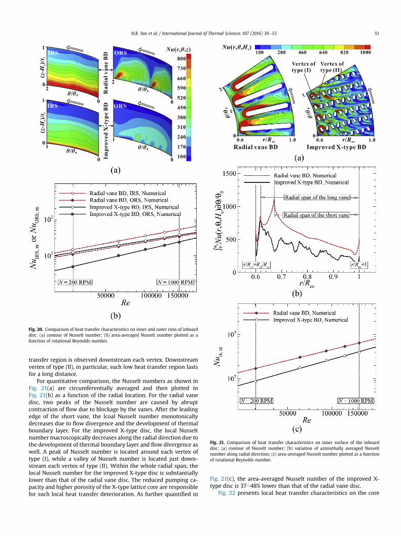
Fig. 20. Comparison of heat transfer characteristics on inner and outer rims of inboarddisc: (a) contour of Nusselt number; (b) area-averaged Nusselt number plotted as afunction of rotational Reynolds number.
Fig. 21. Comparison of heat transfer characteristics on inner surface of the inboarddisc: (a) contour of Nusselt number; (b) variation of azimuthally averaged Nusseltnumber along radial direction; (c) area-averaged Nusselt number plotted as a functionof rotational Reynolds number.
H.B. Yan et al. / International Journal of Thermal Sciences 107 (2016) 39e55 51
transfer region is observed downstream each vertex. Downstreamvertex of type (II), in particular, such low heat transfer region lastsfor a long distance.
For quantitative comparison, the Nusselt numbers as shown inFig. 21(a) are circumferentially averaged and then plotted inFig. 21(b) as a function of the radial location. For the radial vanedisc, two peaks of the Nusselt number are caused by abruptcontraction of flow due to blockage by the vanes. After the leadingedge of the short vane, the lcoal Nusselt number monotonicallydecreases due to flow divergence and the development of thermalboundary layer. For the improved X-type disc, the local Nusseltnumber macroscopically decreases along the radial direction due tothe development of thermal boundary layer and flow divergence aswell. A peak of Nusselt number is located around each vertex oftype (I), while a valley of Nusselt number is located just down-stream each vertex of type (II). Within the whole radial span, thelocal Nusselt number for the improved X-type disc is substantiallylower than that of the radial vane disc. The reduced pumping ca-pacity and higher porosity of the X-type lattice core are responsiblefor such local heat transfer deterioration. As further quantified in
Fig. 21(c), the area-averaged Nusselt number of the improved X-type disc is 37e48% lower than that of the radial vane disc.
Fig. 22 presents local heat transfer characteristics on the core
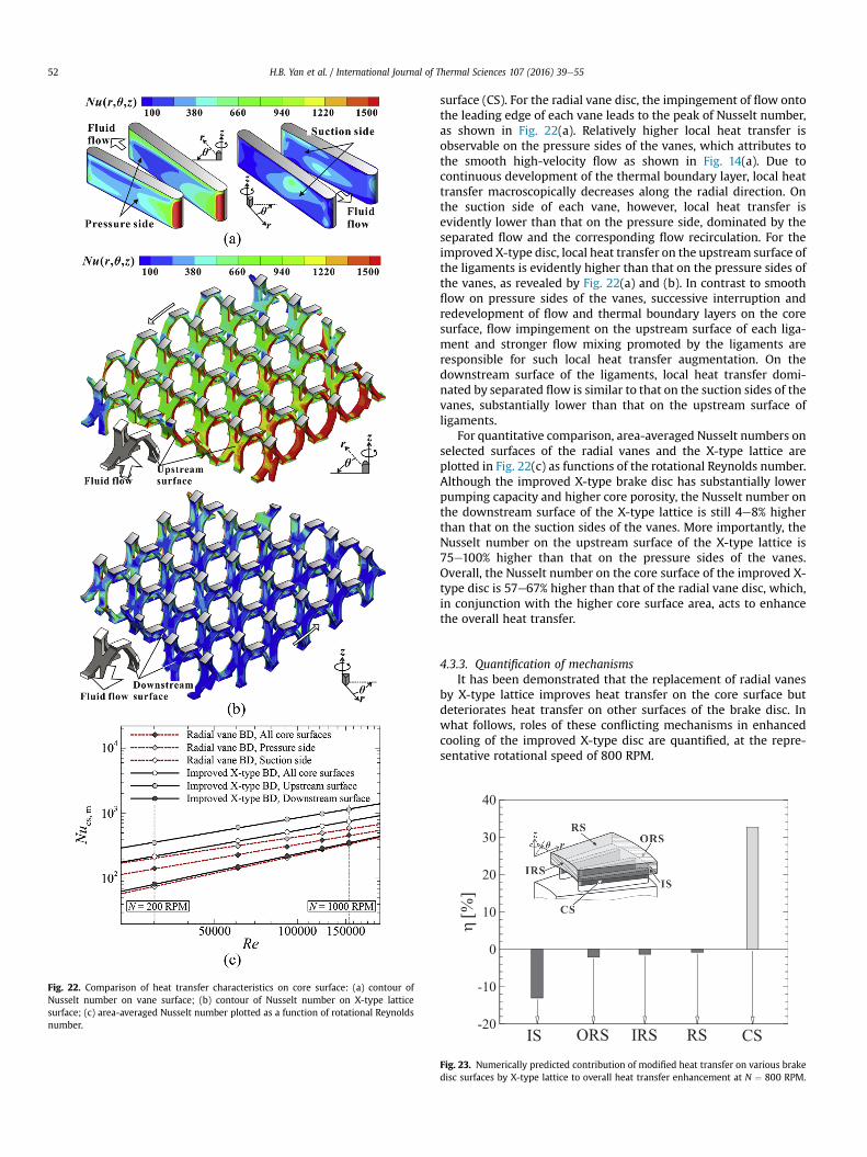
Fig. 22. Comparison of heat transfer characteristics on core surface: (a) contour ofNusselt number on vane surface; (b) contour of Nusselt number on X-type latticesurface; (c) area-averaged Nusselt number plotted as a function of rotational Reynoldsnumber.
H.B. Yan et al. / International Journal of Thermal Sciences 107 (2016) 39e5552
surface (CS). For the radial vane disc, the impingement of flow ontothe leading edge of each vane leads to the peak of Nusselt number,as shown in Fig. 22(a). Relatively higher local heat transfer isobservable on the pressure sides of the vanes, which attributes tothe smooth high-velocity flow as shown in Fig. 14(a). Due tocontinuous development of the thermal boundary layer, local heattransfer macroscopically decreases along the radial direction. Onthe suction side of each vane, however, local heat transfer isevidently lower than that on the pressure side, dominated by theseparated flow and the corresponding flow recirculation. For theimproved X-type disc, local heat transfer on the upstream surface ofthe ligaments is evidently higher than that on the pressure sides ofthe vanes, as revealed by Fig. 22(a) and (b). In contrast to smoothflow on pressure sides of the vanes, successive interruption andredevelopment of flow and thermal boundary layers on the coresurface, flow impingement on the upstream surface of each liga-ment and stronger flow mixing promoted by the ligaments areresponsible for such local heat transfer augmentation. On thedownstream surface of the ligaments, local heat transfer domi-nated by separated flow is similar to that on the suction sides of thevanes, substantially lower than that on the upstream surface ofligaments.
For quantitative comparison, area-averaged Nusselt numbers onselected surfaces of the radial vanes and the X-type lattice areplotted in Fig. 22(c) as functions of the rotational Reynolds number.Although the improved X-type brake disc has substantially lowerpumping capacity and higher core porosity, the Nusselt number onthe downstream surface of the X-type lattice is still 4e8% higherthan that on the suction sides of the vanes. More importantly, theNusselt number on the upstream surface of the X-type lattice is75e100% higher than that on the pressure sides of the vanes.Overall, the Nusselt number on the core surface of the improved X-type disc is 57e67% higher than that of the radial vane disc, which,in conjunction with the higher core surface area, acts to enhancethe overall heat transfer.
4.3.3. Quantification of mechanismsIt has been demonstrated that the replacement of radial vanes
by X-type lattice improves heat transfer on the core surface butdeteriorates heat transfer on other surfaces of the brake disc. Inwhat follows, roles of these conflicting mechanisms in enhancedcooling of the improved X-type disc are quantified, at the repre-sentative rotational speed of 800 RPM.
η[%
]
-20
-10
0
10
20
30
40
IS ORS CSIRS RS
Fig. 23. Numerically predicted contribution of modified heat transfer on various brakedisc surfaces by X-type lattice to overall heat transfer enhancement at N ¼ 800 RPM.
�Nuoverall ¼ C1;isC2;isNuis;m þ C1;orsC2;orsNuors;m þ C1;irsC2;irsNuirs;m þ C1;rsC2;rsNurs;m þ C1;csC2;csNucs;m
�Radial vane BD (8a)
�Nuoverall ¼ C1;isC2;isNuis;m þ C1;orsC2;orsNuors;m þ C1;irsC2;irsNuirs;m þ C1;rsC2;rsNurs;m þ C1;csC2;csNucs;m
�Improved X�type BD (8b)
H.B. Yan et al. / International Journal of Thermal Sciences 107 (2016) 39e55 53
The present numerical results reveal that the heat transfer ratethrough an r�q cross-section of the core at z/Hc ¼ 0.583 for theradial vane brake disc and z/Hc ¼ 0.464 for the improved X-typebrake disc is approximately zero. Henceforth, only the inboard partof each brake disc located over the “adiabatic” cross-section isconsidered. The numerical results also indicate that the area-averaged effective Nusselt number (Nue, m) as presented inFig.11(b) exhibits a quantitative deviation of less than 0.4% from theoverall Nusselt number (Nuoverall) defined as [45]:
Nuoverall ¼Rrok
ð0:5QtÞ.Aref
Trs; m � Ta(7)
where the reference area (Aref) denotes the rubbing surface area ofthe inboard disc. For convenience, the overall Nusselt numberdefined in Eq. (7) is used as an alternative in subsequent analysis.
According to energy balance of the selected system, the overallNusselt number for the radial vane disc and that for the improvedX-type disc may be separately decomposed as [45]:
where subscripts “is”, “ors”, “irs” and “rs” denote the inner surface,the outer rim surface, the inner rim surface and the rubbing surfaceof the inboard disc, respectively; subscript “cs” denotes the core
hcs¼�C1;csC2;csNucs;m
�ImprovedX�typeBD�
�C1;csC2;csNucs;m
�RadialvaneBD
ðNuoverallÞRadialvaneBD(10)
surface; and subscript “m” denotes the area-averaged value. Thecoefficients C1 and C2 for a specific surface, e.g., CS, are given by:
C1;cs ¼ Acs
.Aref (9a)
C2;cs ¼�Tcs;m�TaTrs;m � Ta
�8>>>>><>>>>>:
ZCS
½Tcsðr; q; zÞ � Ta�hcsðr; q; zÞdAZCS
½Tcsðr; q; zÞ � Ta�dA1
hcs;m
9>>>>>=>>>>>;(9b)
C1 represents the contribution of heat transfer area while C2signifies the detrimental effect of material thermal resistance. Eachterm on the right-hand side of Eq. (8) (e.g., C1, csC2, csNucs, m) rep-resents the contribution of heat transfer on a specific surface (e.g.,CS) to overall heat transfer.
Subsequently, the contribution of improved or deteriorated heattransfer on a specific surface (e.g., CS) to overall heat transferenhancement may be quantified as [45]:
The values of C1, C2 and area-averaged Nusselt number (Num) forIS, ORS, IRS and RS of the inboard disc as well as that for CS aresummarized in Table 4. Both brake discs have similar values of C2for IS, ORS, IRS and RS, respectively. However, the coefficient C2, csfor the improved X-type disc is evidently lower than that for theother disc, implying a more significant yet detrimental effect ofmaterial thermal resistance on the improved X-type disc. The su-periority of the new brake disc is hence expected to be moreevident when a highly conductive material is used.
As quantified in Fig. 23, the diminished Nusselt numbers on IS,ORS, IRS and RS reduce the overall Nusselt number by 13.1%, 2.1%,1.4% and 0.9%, respectively. However, the substantially enhancedNusselt number and more heat transfer area on the core surfaceenhance the overall Nusselt number by 32.7%; and this is thegoverning heat transfer enhancement mechanism. Eventually, theimproved X-type disc exhibits a 15.2% higher overall Nusseltnumber than the radial vane disc.
5. Conclusions
This paper introduces an improved design of the X-type lattice
cored ventilated brake disc proposed in a previous study. Twelveannular sector X-type lattice components are integrated into theventilated channel as a heat dissipation core. Its thermo-fluidiccharacteristics obtained both experimentally and numerically arepresented along with direct comparisons with those of a radialvane brake disc and the preliminary X-type brake disc. Conclusionsdrawn in this study are summarized as follows.
(1) Experimental results indicate that the improved X-typebrake disc exhibits a circumferentially isotropic heat transferpattern on its rubbing surface, which is similar to that of theradial vane brake disc, but in sharp contrast to the circum-ferentially anisotropic heat transfer pattern of the pre-liminary X-type brake disc. Hence, the operatingtemperature on the rubbing surface is uniformly reduced.
(2) Within the typical operating range of a passenger vehicle(i.e., 25e124 km/h), experimental results reveal that the
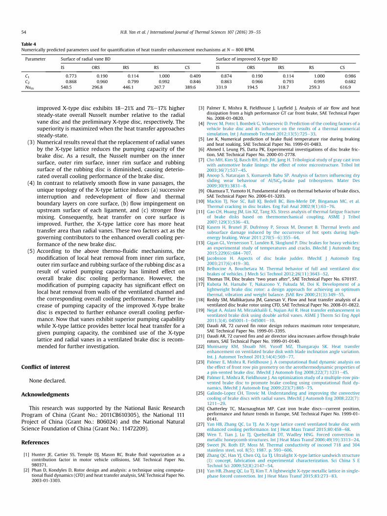
Table 4Numerically predicted parameters used for quantification of heat transfer enhancement mechanisms at N ¼ 800 RPM.
Parameter Surface of radial vane BD Surface of improved X-type BD
IS ORS IRS RS CS IS ORS IRS RS CS
C1 0.773 0.190 0.114 1.000 0.409 0.874 0.190 0.114 1.000 0.986C2 0.868 0.960 0.799 0.992 0.846 0.863 0.966 0.793 0.995 0.682Num 540.5 296.8 446.1 267.7 389.6 331.9 194.5 318.7 259.3 616.9
H.B. Yan et al. / International Journal of Thermal Sciences 107 (2016) 39e5554
improved X-type disc exhibits 18e21% and 7%e17% highersteady-state overall Nusselt number relative to the radialvane disc and the preliminary X-type disc, respectively. Thesuperiority is maximized when the heat transfer approachessteady-state.
(3) Numerical results reveal that the replacement of radial vanesby the X-type lattice reduces the pumping capacity of thebrake disc. As a result, the Nusselt number on the innersurface, outer rim surface, inner rim surface and rubbingsurface of the rubbing disc is diminished, causing deterio-rated overall cooling performance of the brake disc.
(4) In contrast to relatively smooth flow in vane passages, theunique topology of the X-type lattice induces (a) successiveinterruption and redevelopment of flow and thermalboundary layers on core surface, (b) flow impingement onupstream surface of each ligament, and (c) stronger flowmixing. Consequently, heat transfer on core surface isimproved. Further, the X-type lattice core has more heattransfer area than radial vanes. These two factors act as thegoverning contributors to the enhanced overall cooling per-formance of the new brake disc.
(5) According to the above thermo-fluidic mechanisms, themodification of local heat removal from inner rim surface,outer rim surface and rubbing surface of the rubbing disc as aresult of varied pumping capacity has limited effect onoverall brake disc cooling performance. However, themodification of pumping capacity has significant effect onlocal heat removal from walls of the ventilated channel andthe corresponding overall cooling performance. Further in-crease of pumping capacity of the improved X-type brakedisc is expected to further enhance overall cooling perfor-mance. Now that vanes exhibit superior pumping capabilitywhile X-type lattice provides better local heat transfer for agiven pumping capacity, the combined use of the X-typelattice and radial vanes in a ventilated brake disc is recom-mended for further investigation.
Conflict of interest
None declared.
Acknowledgments
This research was supported by the National Basic ResearchProgram of China (Grant No.: 2011CB610305), the National 111Project of China (Grant No.: B06024) and the National NaturalScience Foundation of China (Grant No.: 11472209).
References
[1] Hunter JE, Cartier SS, Temple DJ, Mason RC, Brake fluid vaporization as acontribution factor in motor vehicle collisions, SAE Technical Paper No.980371.
[2] Phan D, Kondyles D, Rotor design and analysis: a technique using computa-tional fluid dynamics (CFD) and heat transfer analysis, SAE Technical Paper No.2003-01-3303.
[3] Palmer E, Mishra R, Fieldhouse J, Layfield J, Analysis of air flow and heatdissipation from a high performance GT car front brake, SAE Technical PaperNo. 2008-01-0820.
[4] Pevec M, Potrc I, Bombek G, Vranesevic D. Prediction of the cooling factors of avehicle brake disc and its influence on the results of a thermal numericalsimulation. Int J Automob Technol 2012;13(5):725e33.
[5] Lee K, Numerical prediction of brake fluid temperature rise during brakingand heat soaking, SAE Technical Paper No. 1999-01-0483.
[6] Ahmed I, Leung PS, Datta PK, Experimental investigations of disc brake fric-tion, SAE Technical Paper No. 2000-01-2778.
[7] Cho MH, Kim SJ, Basch RH, Fash JW, Jang H. Tribological study of gray cast ironwith automotive brake linings: the effect of rotor microstructure. Tribol Int2003;36(7):537e45.
[8] Anoop S, Natarajan S, Kumaresh Babu SP. Analysis of factors influencing drysliding wear behaviour of Al/SiCp-brake pad tribosystem. Mater Des2009;30(9):3831e8.
[9] Okamura T, Yumoto H, Fundamental study on thermal behavior of brake discs,SAE Technical Paper No. 2006-01-3203.
[10] Mackin TJ, Noe SC, Ball KJ, Bedell BC, Bim-Merle DP, Bingaman MC, et al.Thermal cracking in disc brakes. Eng Fail Anal 2002;9(1):63e76.
[11] Gao CH, Huang JM, Lin XZ, Tang XS. Stress analysis of thermal fatigue fractureof brake disks based on thermomechanical coupling. ASME J Tribol2007;129(3):536e43.
[12] Kasem H, Brunel JF, Dufr�enoy P, Siroux M, Desmet B. Thermal levels andsubsurface damage induced by the occurrence of hot spots during high-energy braking. Wear 2011;270(5e6):355e64.
[13] Gigan GL, Vernersson T, Lund�en R, Skoglund P. Disc brakes for heavy vehicles:an experimental study of temperatures and cracks. IMechE J Automob Eng2015;229(6):684e707.
[14] Jacobsson H. Aspects of disc brake judder. IMechE J Automob Eng2003;217(6):419e30.
[15] Belhocine A, Bouchetara M. Thermal behavior of full and ventilated discbrakes of vehicles. J Mech Sci Technol 2012;26(11):3643e52.
[16] Thomas TH, Disc brakes “two years after”, SAE Technical Paper No. 670197.[17] Kubota M, Hamabe T, Nakazono Y, Fukuda M, Doi K. Development of a
lightweight brake disc rotor: a design approach for achieving an optimumthermal, vibration and weight balance. JSAE Rev 2000;21(3):349e55.
[18] Reddy SM, Mallikarjuna JM, Ganesan V, Flow and heat transfer analysis of aventilated disc brake rotor using CFD, SAE Technical Paper No. 2008-01-0822.
[19] Nejat A, Aslani M, Mirzakhalili E, Najian Asl R. Heat transfer enhancement inventilated brake disk using double airfoil vanes. ASME J Therm Sci Eng Appl2011;3(4). 045001-1e045001e10.
[20] Daudi AR, 72 curved fin rotor design reduces maximum rotor temperature,SAE Technical Paper No. 1999-01-3395.
[21] Daudi AR, 72 curved fins and air director idea increases airflow through brakerotors, SAE Technical Paper No. 1999-01-0140.
[22] Munisamy KM, Shuaib NH, Yusoff MZ, Thangaraju SK. Heat transferenhancement on ventilated brake disk with blade inclination angle variation.Int. J. Automot Technol 2013;14(4):569e77.
[23] Palmer E, Mishra R, Fieldhouse J. A computational fluid dynamic analysis onthe effect of front row pin geometry on the aerothermodynamic properties ofa pin-vented brake disc. IMechE J Automob Eng 2008;222(7):1231e45.
[24] Palmer E, Mishra R, Fieldhouse J. An optimization study of a multiple-row pin-vented brake disc to promote brake cooling using computational fluid dy-namics. IMechE J Automob Eng 2009;223(7):865e75.
[25] Galindo-Lopez CH, Tirovic M. Understanding and improving the convectivecooling of brake discs with radial vanes. IMechE J Automob Eng 2008;222(7):1211e29.
[26] Chatterley TC, Macnaughtan MP, Cast iron brake discsdcurrent position,performance and future trends in Europe, SAE Technical Paper No. 1999-01-0141.
[27] Yan HB, Zhang QC, Lu TJ. An X-type lattice cored ventilated brake disc withenhanced cooling performance. Int J Heat Mass Transf 2015;80:458e68.
[28] Wen T, Tian J, Lu TJ, Queheillalt DT, Wadley HNG. Forced convection inmetallic honeycomb structures. Int J Heat Mass Transf 2006;49(19):3313e24.
[29] Sweet JN, Roth EP, Moss M. Thermal conductivity of inconel 718 and 304stainless steel, vol. 8(5); 1987. p. 593e606.
[30] Zhang QC, Han YJ, Chen CQ, Lu TJ. Ultralight X-type lattice sandwich structure(I): concept, fabrication and experimental characterization. Sci China S ETechnol Sci 2009;52(8):2147e54.
[31] Yan HB, Zhang QC, Lu TJ, Kim T. A lightweight X-type metallic lattice in single-phase forced convection. Int J Heat Mass Transf 2015;83:273e83.

H.B. Yan et al. / International Journal of Thermal Sciences 107 (2016) 39e55 55
[32] Lyall ME. Heat transfer from low aspect ratio pin fins. Master thesis. Blacks-burg, VA: Virginia Polytechnic Institute and State University; 2006. p. 61.
[33] Yan HB, Mew T, Lee MG, Kang KJ, Lu TJ, kienh€ofer FW, et al. Thermofluidiccharacteristics of a porous ventilated brake disk. ASME J Heat Transf2015;137(2). 022601-1e022601-11.
[34] Bergman TL, Lavine AS, Incropera FP, Dewitt DP. Fundamentals of heat andmass transfer. 7th edn. Hoboken, New Jersey: John Wiley & Sons Inc.; 2011.p. 885.
[35] Coleman HW, Steele WG. Experimentation, validation, and uncertainty anal-ysis for engineers. 3rd edn. Hoboken, New Jersey: John Wiley & Sons Inc.;2009.
[36] Wallis L, Leonardi E, Milton B, Joseph P. Air flow and heat transfer in venti-lated disc brake rotors with diamond and tear-drop pillars. Numer Heat TransfA Appl 2002;41(6e7):643e55.
[37] CFX 14.5. ANSYS CFX-solver theory guide. Canonsburg, Pennsylvania: ANSYSInc.; 2012.
[38] Menter FR. Two-equation eddy-viscosity turbulence models for engineeringapplications. AIAA J 1994;32(8):1598e605.
[39] Mangani L, Casartelli E, Mauri S. Assessment of various turbulence models in ahigh pressure ratio centrifugal compressor with an object oriented CFD code.ASME J Turbomach 2012;134(6). 061033-1e061033-10.
[40] Reddy SM, Mallikarjuna JM, Ganesan V. Flow and heat transfer analysisthrough a brake discdA CFD approach. In: Proceedings of the ASME 2006International mechanical engineering congress and exposition, vol. 3. Chicago,Illinois, USA: ASME; 2006. p. 481e5.
[41] Johnson DA, Sperandei BA, Gilbert R. Analysis of the flow through a ventedautomotive brake rotor. ASME J Fluids Eng 2003;125(6):979e86.
[42] Limpert R, Cooling analysis of disc brake rotors, SAE Technical Paper No.751014.
[43] Sisson AE, Thermal analysis of vented brake rotors, SAE Technical Paper No.780352.
[44] Hudson MD, Ruhl RL, Ventilated brake rotor air flow investigation, SAETechnical Paper No. 971033.
[45] Yan HB, Feng SS, Yang XH, Lu TJ. Role of cross-drilled holes in enhancedcooling of ventilated brake discs. Appl Therm Eng 2015;91:318e33.