international unmanned aerial vehicles competition
TRANSCRIPT
INTERNATIONAL UNMANNED AERIAL VEHICLES COMPETITION
DETAILED DESIGN REPORT
TEAM NAME : CAKRA DIRGA UM
VEHICLE TYPE : FIXED WING / ROTARY WING
UNIVERSITY : Universitas Negeri Malang (UM), Indonesia
TEAM CAPTAIN : Firman Lutfi Fawzan Adhiima
UNIVERSITAS NEGERI MALANG
INDONESIA
2021
Dirga Cakra UM 2
TEAM NAME : CAKRA DIRGA UM
VEHICLE TYPE : FIXED WING / ROTARY WING
UNIVERSITY : Universitas Negeri Malang (UM), Indonesia
TEAM CAPTAIN : Firman Lutfi Fawzan Adhiima
1. PROJECT SUMMARY
1.1 Method Followed in Design
The Cakra Dirga Unmanned Aerial Vehicle (UAV) model has a good aerodynamic airframe
performance, so it can complete the missions optimally on flight mission 1 and 2. The UAV is
designed with winglets to reduce wingtip vortex that causes turbulence in which the drag could
decrease. Moreover, the vehicle is also equipped with a gyro and accelerometer, barometer,
magnetometer sensors, and additional Global Positioning System (GPS) components that
allow the UAV to carry out missions autonomously. In addition, this UAV is also equipped with
3 fail-safe systems, including: (1) excessive circuit breaker fuses, (2) arm switches on the UAV
and Ground Control system (GCS), and (3) Return to Launch (RTL) program algorithm. The
RTL will command the UAV to return to launch when the signal of the transmitter and GCS
loses.
The UAV is made from polystyrene base material with laminated outside parts to reduce
turbulence in the surface area, the All Up Weight (AUW) of the UAV is 2.1 kg. The battery has
capacity of 14.8V 4400 mAh. Therefore, the UAV is able to travel for longer than 6 minutes
with a maximum speed of 37m/s .
1.2 Team Organization
This team is led by Firman Lutfi Fawzan Adhiima, who is responsible in coordinating the
team’s performance, reporting all documents, and establishing communication with the
committee. Two lecturers are involved as the advisers that is Dr. Eng Siti Sendari and Yoyok
Adisetio L., M.Si as the technical advisor in developing the conceptual design and the
administrative advisor in managing the team performance, respectively.
The organizational structure of Cakra Dirga from Universitas Negeri Malang (UM), Indonesia,
is displayed in Figure 1.
Figure 1. Team Organization
Rif’atu Nuril Laily
Diana Elisia
R&D
Yoyok Adisetio L., M.Si
Administrative Advisor
Dr. Eng Siti Sendari,
S.T.,M.T.
Technical Advisor Captain
Firman Lutfi Fawzan
Adhiima
Rizky Ramadhan M.
Taufiqul Hakim
Design & Analyzing
Nurdin Khoirurizka
Achmad Aldi S.
Electric & Programming
M. Andi Fauzi
Mechanic Manufactur
3 DIRGA CAKRA UM
Furthermore, the team is divided into four divisions as explained on Figure 1 : (1) The
research and development (R&D) division is responsible for comparing and analyzing the data;
(2) The design and analysis division is in charge of creating the designs from the data that has
been compiled and conducting CFD tests from the 3D designs; (3) The electronics and
programming division is in responsible for selecting the components used and programming
the GCS; (4) The mechanical division is in charge of making the UAV.
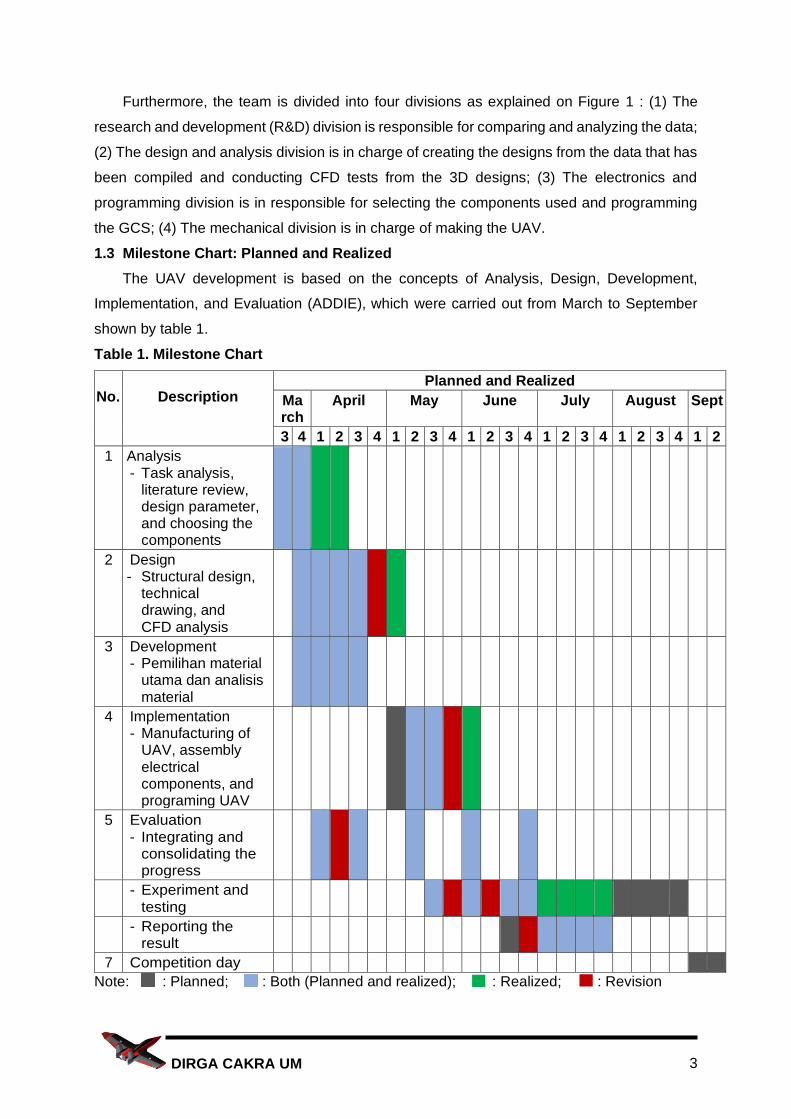
1.3 Milestone Chart: Planned and Realized
The UAV development is based on the concepts of Analysis, Design, Development,
Implementation, and Evaluation (ADDIE), which were carried out from March to September
shown by table 1.
Table 1. Milestone Chart
No. Description Planned and Realized
March
April May June July August Sept
3 4 1 2 3 4 1 2 3 4 1 2 3 4 1 2 3 4 1 2 3 4 1 2
1 Analysis - Task analysis,
literature review, design parameter, and choosing the components
2 Design - Structural design,
technical drawing, and CFD analysis
3 Development - Pemilihan material
utama dan analisis material
4 Implementation - Manufacturing of
UAV, assembly electrical components, and programing UAV
5 Evaluation - Integrating and
consolidating the progress
- Experiment and testing
- Reporting the result
7 Competition day
Note: : Planned; : Both (Planned and realized); : Realized; : Revision
4 DIRGA CAKRA UM
2. Detailed Design
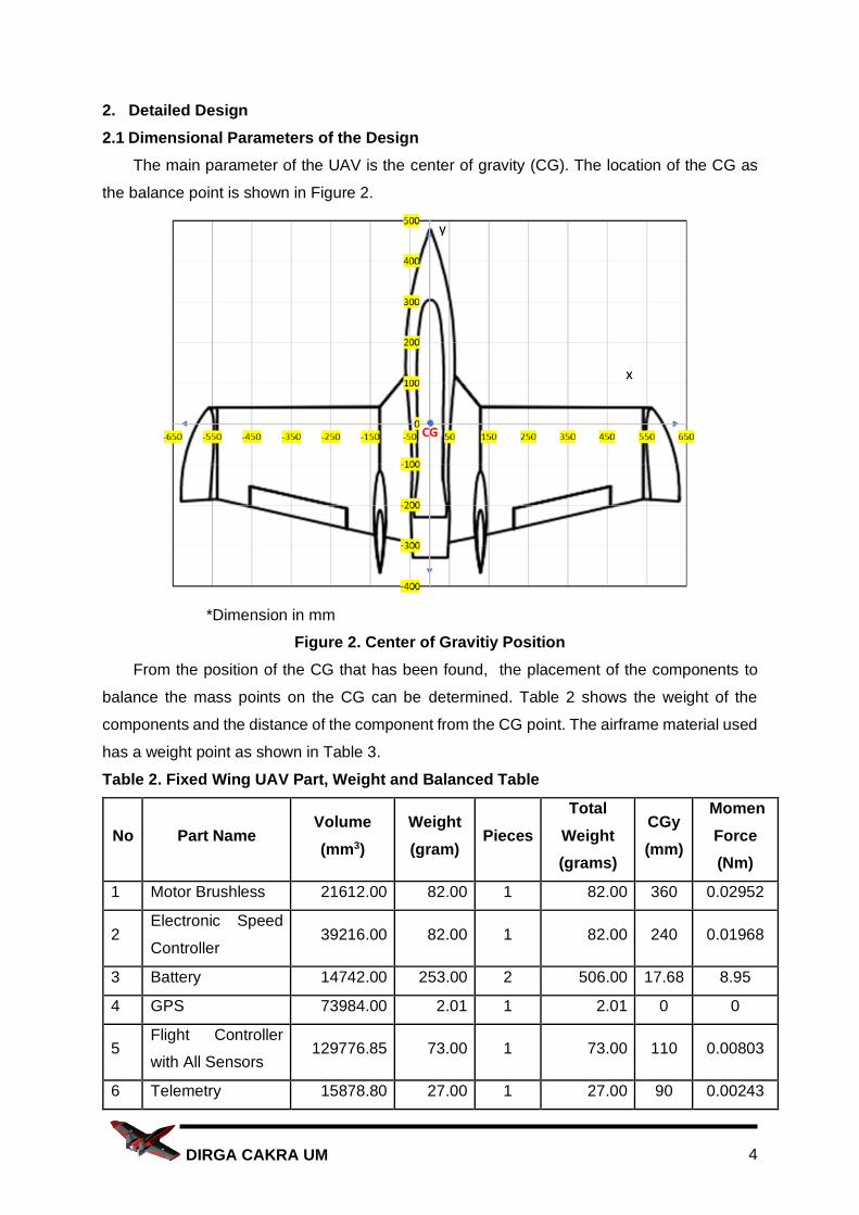
2.1 Dimensional Parameters of the Design
The main parameter of the UAV is the center of gravity (CG). The location of the CG as
the balance point is shown in Figure 2.
*Dimension in mm
Figure 2. Center of Gravitiy Position
From the position of the CG that has been found, the placement of the components to
balance the mass points on the CG can be determined. Table 2 shows the weight of the
components and the distance of the component from the CG point. The airframe material used
has a weight point as shown in Table 3.
Table 2. Fixed Wing UAV Part, Weight and Balanced Table
No Part Name Volume
(mm3)
Weight
(gram) Pieces
Total
Weight
(grams)
CGy
(mm)
Momen
Force
(Nm)
1 Motor Brushless 21612.00 82.00 1 82.00 360 0.02952
2 Electronic Speed
Controller 39216.00 82.00 1 82.00 240 0.01968
3 Battery 14742.00 253.00 2 506.00 17.68 8.95
4 GPS 73984.00 2.01 1 2.01 0 0
5 Flight Controller
with All Sensors 129776.85 73.00 1 73.00 110 0.00803
6 Telemetry 15878.80 27.00 1 27.00 90 0.00243
x
y
5 DIRGA CAKRA UM
No Part Name Volume
(mm3)
Weight
(gram) Pieces
Total
Weight
(grams)
CGy
(mm)
Momen
Force
(Nm)
7 Receiver 903.00 0.05 1 0.05 60 0.000003
8 Servo 11502.34 17.00 2 34.00 150 0.00255
9 Arm Switch 171.00 0.21 1 0.21 75 1.58x10⁻⁵
10 Power Module 13356.00 14.00 1 14.00 130 0.00182
11 FPV Camera 3136.00 0.13 1 0.13 500 0.000065
12 VTX 264.00 5.00 1 5.00 300 0.00015
13 Antenna VTX 174.00 10.00 1 10.00 200 0.0002
14 Propeller 21336.00 40.00 1 40.00 425 0.0017
15 Release payload 320098.00 100.00 1 100.00 440 0.044
16 Buzzer 36.00 2.50 1 2.50 50 0.000125
Table 3. Fixed Wing UAV Material Weight
No Part Name Weight (grams)
1 Fuselage 528
2 Wing (Both) 339
3 Vertical Stabilizer (Both) 182
4 Surface Control (Both) 27
Total 1076
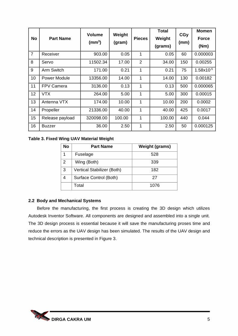
2.2 Body and Mechanical Systems
Before the manufacturing, the first process is creating the 3D design which utilizes
Autodesk Inventor Software. All components are designed and assembled into a single unit.
The 3D design process is essential because it will save the manufacturing proses time and
reduce the errors as the UAV design has been simulated. The results of the UAV design and
technical description is presented in Figure 3.
6 DIRGA CAKRA UM
Figure 3. UAV Design
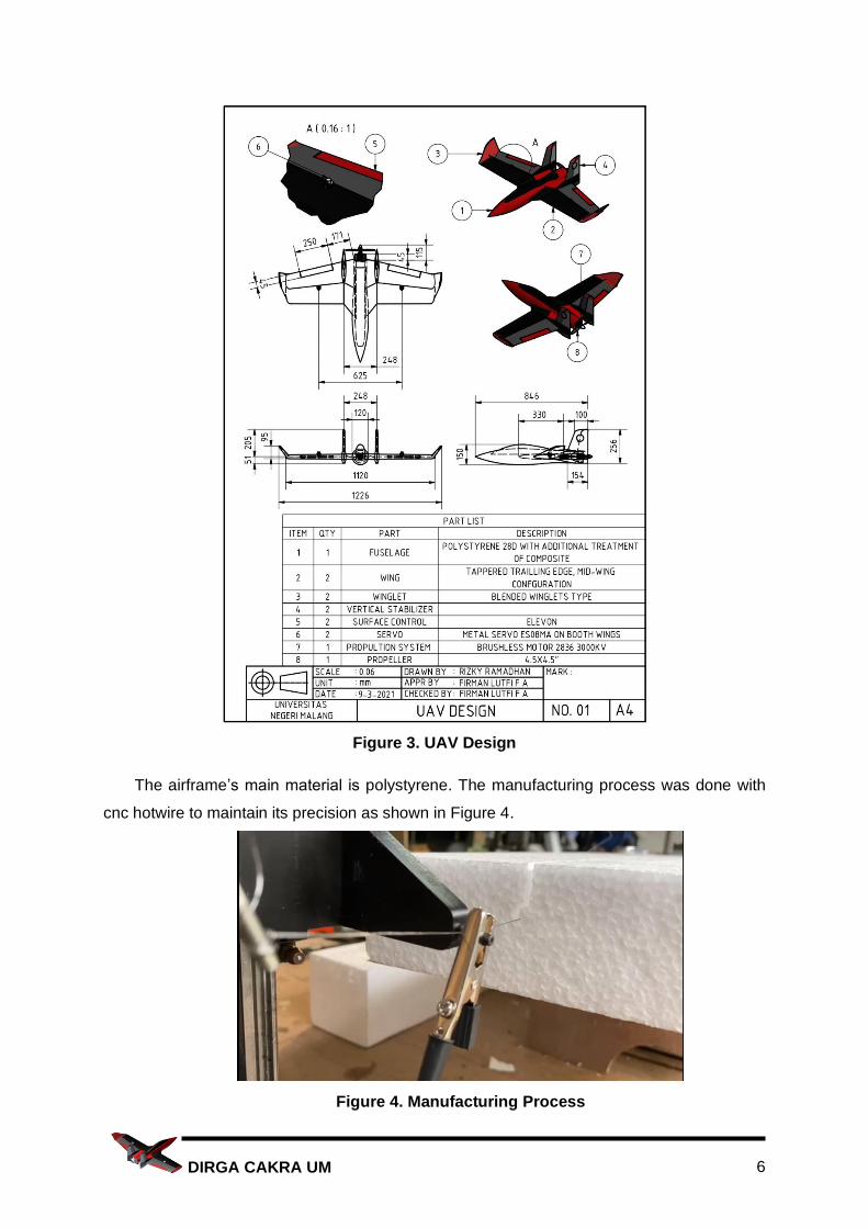
The airframe’s main material is polystyrene. The manufacturing process was done with
cnc hotwire to maintain its precision as shown in Figure 4.
Figure 4. Manufacturing Process
7 DIRGA CAKRA UM
To combine all airframe parts, special glue for polystyrene is used so that the connection
between components becomes rigid and light. After this process, all parts of the airframe of
the UAV are laminated to make the surface smoother and strengthen the structure. The carbon
tube is inserted to strengthen the wing during flying, so it will not deform when there are
additional loads or abnormal wind. Adequate material specifications will improve aircraft
performance in terms of strength and flight capability.
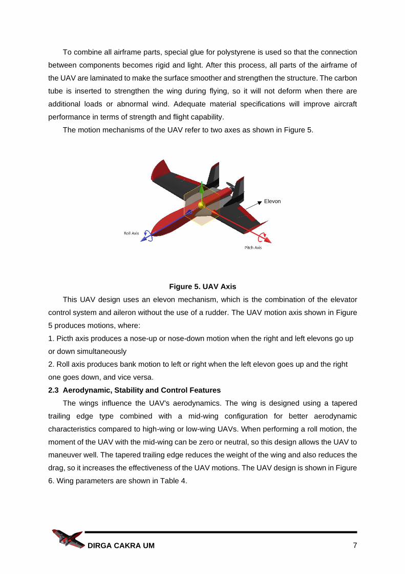
The motion mechanisms of the UAV refer to two axes as shown in Figure 5.
Figure 5. UAV Axis
This UAV design uses an elevon mechanism, which is the combination of the elevator
control system and aileron without the use of a rudder. The UAV motion axis shown in Figure
5 produces motions, where:
1. Picth axis produces a nose-up or nose-down motion when the right and left elevons go up
or down simultaneously
2. Roll axis produces bank motion to left or right when the left elevon goes up and the right
one goes down, and vice versa.
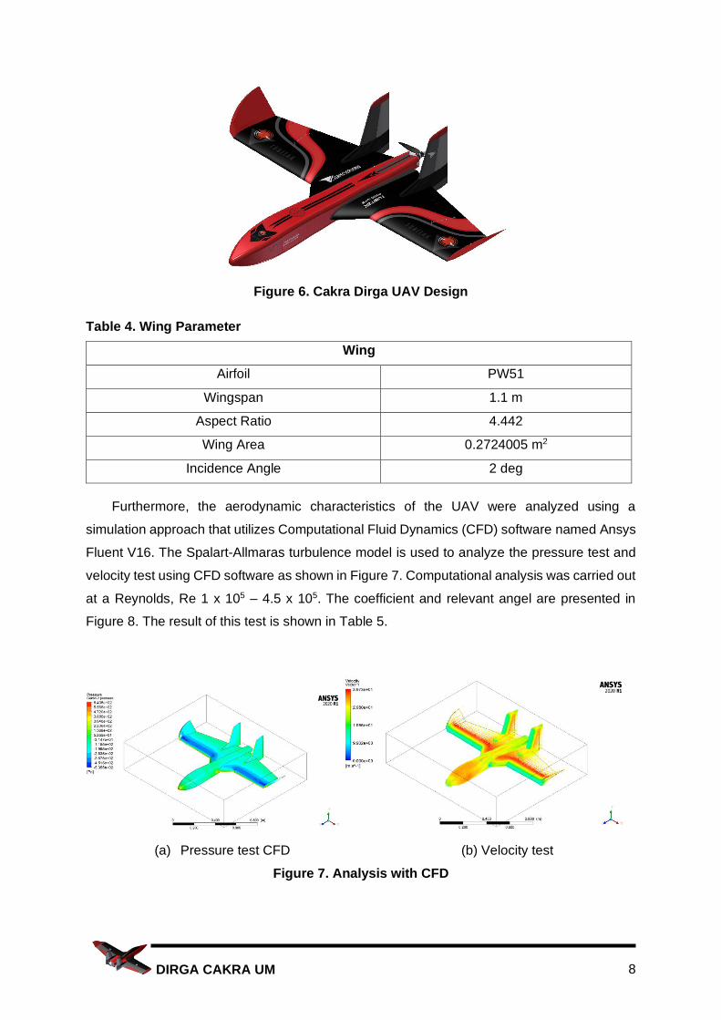
2.3 Aerodynamic, Stability and Control Features
The wings influence the UAV's aerodynamics. The wing is designed using a tapered
trailing edge type combined with a mid-wing configuration for better aerodynamic
characteristics compared to high-wing or low-wing UAVs. When performing a roll motion, the
moment of the UAV with the mid-wing can be zero or neutral, so this design allows the UAV to
maneuver well. The tapered trailing edge reduces the weight of the wing and also reduces the
drag, so it increases the effectiveness of the UAV motions. The UAV design is shown in Figure
6. Wing parameters are shown in Table 4.
Elevon
8 DIRGA CAKRA UM
Figure 6. Cakra Dirga UAV Design
Table 4. Wing Parameter
Wing
Airfoil PW51
Wingspan 1.1 m
Aspect Ratio 4.442
Wing Area 0.2724005 m2
Incidence Angle 2 deg
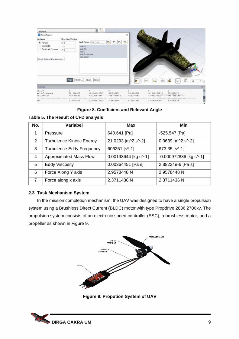
Furthermore, the aerodynamic characteristics of the UAV were analyzed using a
simulation approach that utilizes Computational Fluid Dynamics (CFD) software named Ansys
Fluent V16. The Spalart-Allmaras turbulence model is used to analyze the pressure test and
velocity test using CFD software as shown in Figure 7. Computational analysis was carried out
at a Reynolds, Re 1 x 10⁵ – 4.5 x 10⁵. The coefficient and relevant angel are presented in
Figure 8. The result of this test is shown in Table 5.
(a) Pressure test CFD (b) Velocity test
Figure 7. Analysis with CFD
9 DIRGA CAKRA UM
Figure 8. Coefficient and Relevant Angle
Table 5. The Result of CFD analysis
No. Variabel Max Min
1 Pressure 640.641 [Pa] -525.547 [Pa]
2 Turbulence Kinetic Energy 21.0293 [m^2 s^-2] 0.3639 [m^2 s^-2]
3 Turbulence Eddy Frequency 606251 [s^-1] 673.35 [s^-1]
4 Approximated Mass Flow 0.00193644 [kg s^-1] -0.000972836 [kg s^-1]
5 Eddy Viscosity 0.00364451 [Pa s] 2.88224e-6 [Pa s]
6 Force Along Y axis 2.9578448 N 2.9578448 N
7 Force along x axis 2.3711436 N 2.3711436 N
2.3 Task Mechanism System
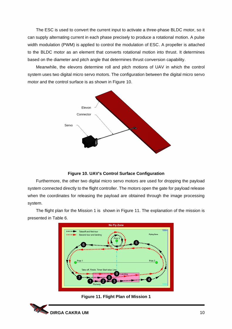
In the mission completion mechanism, the UAV was designed to have a single propulsion
system using a Brushless Direct Current (BLDC) motor with type Propdrive 2836 2700kv. The
propulsion system consists of an electronic speed controller (ESC), a brushless motor, and a
propeller as shown in Figure 9.
Figure 9. Propution System of UAV
10 DIRGA CAKRA UM
The ESC is used to convert the current input to activate a three-phase BLDC motor, so it
can supply alternating current in each phase precisely to produce a rotational motion. A pulse
width modulation (PWM) is applied to control the modulation of ESC. A propeller is attached
to the BLDC motor as an element that converts rotational motion into thrust. It determines
based on the diameter and pitch angle that determines thrust conversion capability.
Meanwhile, the elevons determine roll and pitch motions of UAV in which the control
system uses two digital micro servo motors. The configuration between the digital micro servo
motor and the control surface is as shown in Figure 10.
Figure 10. UAV's Control Surface Configuration
Furthermore, the other two digital micro servo motors are used for dropping the payload
system connected directly to the flight controller. The motors open the gate for payload release
when the coordinates for releasing the payload are obtained through the image processing
system.
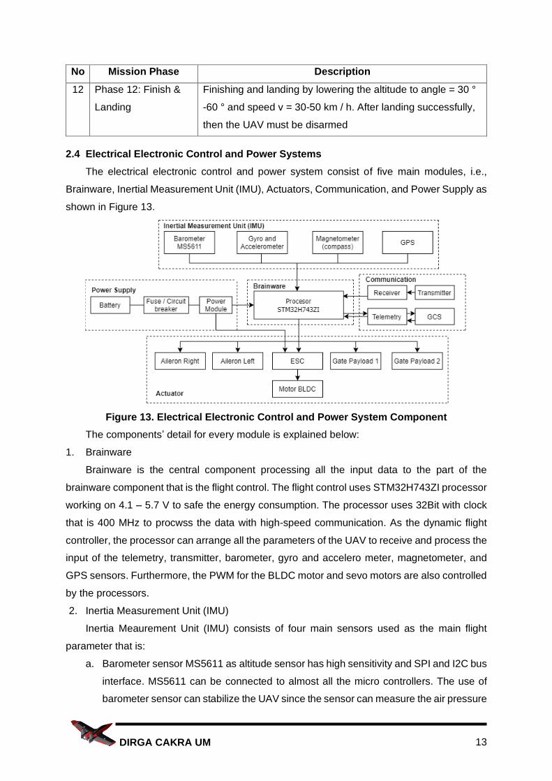
The flight plan for the Mission 1 is shown in Figure 11. The explanation of the mission is
presented in Table 6.
Figure 11. Flight Plan of Mission 1
Elevon
Connector
Servo

11 DIRGA CAKRA UM
Tabel 6. Description of the Flight Plan Mission 1
No Mission Phase Description
1 Phase 1: Start The initial condition is marked as the arming mode and it is in
stabilize mode.
2 Phase 2: Take-off The elevon goes up slightly to prepare for take-off. The
throttle is opened up to 75%. Before 5 seconds, the stabilize
mode is switched into autonomous mode
3 Phase 3: Climb and
Dash
After take-off, the UAV performs the climb by speeding up to
v = 90-130km / h; angle = 50 ° -70 ° to reach the altitude of
50 m
4 Phase 4: Maneuver 1 About 15 meters before approaching Pole 2, the vehicle
performs the Maneuver 1, and the servo at the left elevon
goes up and the servo at the right elevon goes down.
5 Phase 5: Maneuver 2 After maneuvering 1, the UAV performs the dash motion, and
the elevon is in normal condition. Up to 10-20m from Pole 3,
the UAV performs maneuver 2 by turning around Pole 3 up to
3600
6 Phase 6: Maneuver 3 From the end of maneuver 2 the UAV speeds up again and
turn left to perform maneuver 3 by passing Pole 1
7 Phase 7: Speed Up Then the UAV speeds up by passing the starting line and
make a second lap.
8 Phase 8: Second Lap Motion of the UAV on second lap is the same as in maneuver
1, 2 and 3
9 Phase 9: Landing At the end of the second lap of maneuver 3, the UAV reduces
its speed and lower the altitude to prepare for landing.
Meanwhile, the flight plan for the Mission 2 is shown in Figure 12 and the explanation is
in Table 7.
Figure 12. Flight Plan of Mission 2

12 DIRGA CAKRA UM
Tabel 7. Description of the Flight Plan Mission 2
No Mission Phase Description
1 Phase 1: Start The difference lays on the Mission 2 is that the UAV has to
carry two payloads. The initial condition is marked as the
arming mode and it is in stabilize mode.
2 Phase 2: Take-off The elevator goes up slightly to prepare for take-off. The
throttle is opened up to 75%. Before 5 seconds, the stabilize
mode is switched into autonomous mode
3 Phase 3: Climb and
Dash
After take-off, the UAV climbs up, and speeds up to v = 90-
130km / h; angle = 50 ° -70 ° to reach altitude of 50 m
4 Phase 4: Maneuver 1 About 15 meters before approaching the Pole 2, the UAV
performs maneuver 1. The servo at the left elevon goes up,
and the servo at the right elevon goes down.
5 Phase 5: Speed up
and define dropping
area
After maneuver 1, the UAV speeds up with the elevon in
normal condition, observes the dropping area and rushes to
the Pole 1
6 Phase 6: Maneuver 2 In Maneuver 2, the UAV passes by the Pole 1. After
maneuvering 2, the UAV goes toward the Pole 2 for
maneuvering 3
7 Phase 7: Maneuver 3 The UAV performs maneuver 3 on Pole 2 for the second lap
and applies the same parameters as in maneuver 1
8 Phase 8: Dropping
payload 1
After crossing the Pole 2, the UAV carries out the dropping
mission with the initial stage of reducing the speed and
altitude up to 5-10 m. After reaching, the dropping zone, the
vehicle opens the servo to release the first payload and then
the vehicle goes up to reach the initial altitude
9 Phase 9: Maneuver 4 After reaching the Pole 1 reference line, the UAV maneuvers
until it reaches the Pole 2 reference line
10 Phase 10: Maneuver
5 and Droping
payload 2
Then maneuver back to pole 2 with the same parameters as
maneuver 1. Then from the maneuver 5, the UAV performs
the same parameters as dropping payload 1 to drop the
second payload
11 Phase 11: Maneuver
6
The UAV goes to the pole 1 reference line to do maneuver 6
and goes toward the landing point
13 DIRGA CAKRA UM
No Mission Phase Description
12 Phase 12: Finish &
Landing
Finishing and landing by lowering the altitude to angle = 30 °
-60 ° and speed v = 30-50 km / h. After landing successfully,
then the UAV must be disarmed
2.4 Electrical Electronic Control and Power Systems
The electrical electronic control and power system consist of five main modules, i.e.,
Brainware, Inertial Measurement Unit (IMU), Actuators, Communication, and Power Supply as
shown in Figure 13.
Figure 13. Electrical Electronic Control and Power System Component
The components’ detail for every module is explained below:
1. Brainware
Brainware is the central component processing all the input data to the part of the
brainware component that is the flight control. The flight control uses STM32H743ZI processor
working on 4.1 – 5.7 V to safe the energy consumption. The processor uses 32Bit with clock
that is 400 MHz to procwss the data with high-speed communication. As the dynamic flight
controller, the processor can arrange all the parameters of the UAV to receive and process the
input of the telemetry, transmitter, barometer, gyro and accelero meter, magnetometer, and
GPS sensors. Furthermore, the PWM for the BLDC motor and sevo motors are also controlled
by the processors.
2. Inertia Measurement Unit (IMU)
Inertia Meaurement Unit (IMU) consists of four main sensors used as the main flight
parameter that is:
a. Barometer sensor MS5611 as altitude sensor has high sensitivity and SPI and I2C bus
interface. MS5611 can be connected to almost all the micro controllers. The use of
barometer sensor can stabilize the UAV since the sensor can measure the air pressure
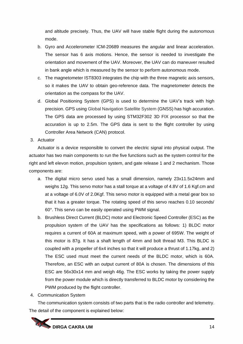
14 DIRGA CAKRA UM
and altitude precisely. Thus, the UAV will have stable flight during the autonomous
mode.
b. Gyro and Accelerometer ICM-20689 measures the angular and linear acceleration.
The sensor has 6 axis motions. Hence, the sensor is needed to investigate the
orientation and movement of the UAV. Moreover, the UAV can do maneuver resulted
in bank angle which is measured by the sensor to perform autonomous mode.
c. The magnetometer IST8303 integrates the chip with the three magnetic axis sensors,
so it makes the UAV to obtain geo-reference data. The magnetometer detects the
orientation as the compass for the UAV.
d. Global Positioning System (GPS) is used to determine the UAV’s track with high
precision. GPS using Global Navigation Satellite System (GNSS) has high accuration.
The GPS data are processed by using STM32F302 3D FIX processor so that the
accuration is up to 2.5m. The GPS data is sent to the flight controller by using
Controller Area Network (CAN) protocol.
3. Actuator
Actuator is a device responsible to convert the electric signal into physical output. The
actuator has two main components to run the five functions such as the system control for the
right and left elevon motion, propulsion system, and gate release 1 and 2 mechanism. Those
components are:
a. The digital micro servo used has a small dimension, namely 23x11.5x24mm and
weighs 12g. This servo motor has a stall torque at a voltage of 4.8V of 1.6 Kgf.cm and
at a voltage of 6.0V of 2.0Kgf. This servo motor is equipped with a metal gear box so
that it has a greater torque. The rotating speed of this servo reaches 0.10 seconds/
60°. This servo can be easily operated using PWM signal.
b. Brushless Direct Current (BLDC) motor and Electronic Speed Controller (ESC) as the
propulsion system of the UAV has the specifications as follows: 1) BLDC motor
requires a current of 60A at maximum speed, with a power of 695W. The weight of
this motor is 87g. It has a shaft length of 4mm and bolt thread M3. This BLDC is
coupled with a propeller of 6x4 inches so that it will produce a thrust of 1.17kg, and 2)
The ESC used must meet the current needs of the BLDC motor, which is 60A.
Therefore, an ESC with an output current of 80A is chosen. The dimensions of this
ESC are 56x30x14 mm and weigh 46g. The ESC works by taking the power supply
from the power module which is directly transferred to BLDC motor by considering the
PWM produced by the flight controller.
4. Communication System
The communication system consists of two parts that is the radio controller and telemetry.
The detail of the component is explained below:

15 DIRGA CAKRA UM
a. The radio control is built by the transmitter and receiver. The transmitter used is FrSky
Taranis QX7. This transmitter features the best in full telemetry capabilities, as well as
RSSI signal strength feedback. The Taranis QX7 transmitter will be paired with the
Crossfire receiver. This receiver has a fairly small dimension of 40x14x9.5mm, but has
a signal range that is quite far up to 3km. This receiver weighs 3.32g making placement
on the UAV easy.The function of the transmitter and receiver is to control the UAV
manually, and to switch the flight mode.
b. The telemetry used in this UAV requires an output power of 500mW and a reception
sensitivity of -117 dBm. This telemetry beam method uses two way full-duplex
communication with a TDM UART interface. The telemetry can send and receive the
data between the GCS and processor properly to complete the flying missions.
5. Power Supply
The power supply can provide the power for the UAV’s devices with three components
that is:
a. The battery used as the UAV power storage has a capacity of 4400mAh. Since the
dimensions of the battery is 145x45x22mm and the total weight of 291g, it requires
CG settings to obtain the right balance. Batteries with nano technology have the
advantage of not being too big and tend to be lighter than other batteries with the
same capacity.
b. Fuse or circuit breaker is the electronic safety device to cut the current circuit to
protect the overcurrent so that it will not damage the other components.
c. Power module transmits the power needs from the battery to the processor. This
power is used to supply the BLDC motor via ESC. In the power module, there are
voltage and current sensors to measure the power consumed which is sent to the
processor.
When the autonomous mode is actived, the UAV will fly according to the flight plan by
utilizing the parameter of IMU. The processor will make a use of the parameter to determine
the PWM received by the actuators as the motion, propulsion, and release mechanism.
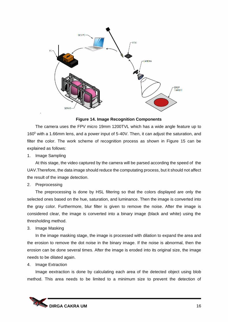
2.5Target Detection and Recognition System
The target detection and recognition system on this UAV use camera images that are
sent to GCS via telemetry. The GCS process the data to get the coordinates and altitude to
determine the dropping zone. When the dropping zone is detected, the task to release payload
will be sent from GCS to the UAV. The following component of this system is shown in Figure
14.
16 DIRGA CAKRA UM
.
Figure 14. Image Recognition Components
The camera uses the FPV micro 19mm 1200TVL which has a wide angle feature up to
1600 with a 1.66mm lens, and a power input of 5-40V. Then, it can adjust the saturation, and
filter the color. The work scheme of recognition process as shown in Figure 15 can be
explained as follows:
1. Image Sampling
At this stage, the video captured by the camera will be parsed according the speed of the
UAV.Therefore, the data image should reduce the computating process, but it should not affect
the result of the image detection.
2. Preprocessing
The preprocessing is done by HSL filtering so that the colors displayed are only the
selected ones based on the hue, saturation, and luminance. Then the image is converted into
the gray color. Furthermore, blur filter is given to remove the noise. After the image is
considered clear, the image is converted into a binary image (black and white) using the
thresholding method.
3. Image Masking
In the image masking stage, the image is processed with dilation to expand the area and
the erosion to remove the dot noise in the binary image. If the noise is abnormal, then the
erosion can be done several times. After the image is eroded into its original size, the image
needs to be dilated again.
4. Image Extraction
Image eextraction is done by calculating each area of the detected object using blob
method. This area needs to be limited to a minimum size to prevent the detection of

17 DIRGA CAKRA UM
unexpected objects. Furthermore, the area will be sorted so that the biggest area value can be
obtained to be declared as a target.
5. Matching Templates
Template matching is done to increase the degree of certainty in objects that are detected
as dropping payload targets.
6. Determining the Target position
When the UAV detects the dropping zone, the GCS gets and saves the coordinates from
the GPS and determines the payload release position. Then, the GCS sends the payload
release coordinates to the UAV.
Figure 15. Work Scheme System
2.6 Flight Performance Parameters
2.6.1 Power
The power required for the UAV is calculated from the total vehicle weight and power
loading data. Data on the total weight of the vehicle is obtained by adding up all components
and the airframe reaches less than 2.5 kg. Meanwhile, the power loading value on our UAV is
273 Watt/Kg to achieve optimal speed and maneuverability on the UAV. Thus, the required
power is calculated using equation 1. Produces a power of 628.5 Watts.
𝑃𝑜𝑤𝑒𝑟 = 𝐴𝑈𝑊 × 𝑃𝑜𝑤𝑒𝑟 𝑙𝑜𝑎𝑑𝑖𝑛𝑔 ................................................ (1)
2.6.2 Battery Capacity
The battery capacity is determined accordingly so that there is no shortage of power. To
determine the capacity of the battery used, it is based on the UAV flight period. If the average
flying speed reaches 30 m/s, the mission can be completed in 247 and it obtained 682.5 Watt.

18 DIRGA CAKRA UM
Then choose a battery that has a voltage of 14.8 Volts so that the current flowing is calculated
by equation 2. Produces a current of 46.11 A
𝐶𝑢𝑟𝑟𝑒𝑛𝑡 =𝐷𝑎𝑦𝑎
𝑉𝑜𝑙𝑡𝑎𝑔𝑒 ........................................................ (2)
Then the minimum required battery capacity is calculated using equation 3, and resulted
in the minimum battery capacity is 3,164 Ah.
𝐾𝑎𝑝𝑎𝑠𝑖𝑡𝑎𝑠 𝑀𝑖𝑛𝑖𝑚𝑢𝑚 𝐵𝑎𝑡𝑒𝑟𝑎𝑖 = 𝐴𝑟𝑢𝑠 × 𝑊𝑎𝑘𝑡𝑢 𝑇𝑒𝑟𝑏𝑎𝑛𝑔 ......................... (3)
2.6.3 Stall Speed
Stall is a condition where the UAV loses its lift so that it can cause the UAV to drop in
altitude drastically. The stall speed is obtained from the Equation 4
𝑉𝑆𝑡𝑎𝑙𝑙 = √2𝑊
𝜌 𝐴 𝐶𝐿 .......................................................... (4)
The total weight of the vehicle (W) is less than 2.5 Kg, with air density (…..) 1.2 Kg/m3,
Surface area (A) 0.2724005 m2, and the wing lift coefficient of type PW51 (CL) is 1.30, then
the stall speed is 3.43 m/s.
2.6.4 Maximum Speed
The maximum speed is the speed that can cause the UAV to lose thrust due to the drag
force. Drag force itself is caused by the pressure difference between the front and rear of the
airfoil, changes in air speed, or due to air friction. The maximum speed that can be achieved
by the UAV is obtained from Equation 5:
𝑉𝑀𝑎𝑥 = √2 𝑇𝑚
𝜌 𝐴𝐷 𝐶𝐷 ......................................................... (5)
The maximum thrust of the The motor is 1.31, with an air density of 1.2 Kg/m3, the UAV
impact area (AD) is 0.00622 m2, and the PW51 (CD) wing lift coefficient is 0.025. Hence, the
maximum speed that can be applied to this UAV is 37.47 m/s.
2.6.5 Turning Radius
Turning radius is the radius needed by a UAV to make a turn. Turning radius is
calculated by Equation 6
𝑅 =𝑉2
𝑔 tan ∅ .............................................................. (6)
So the turning radius of the UAV if it turns at a speed of 30 m/s and a tilt angle of 60° is
29.39 m.
2.7 UAV Cost Distribution
In the manufacturing of this UAV, Cakra Dirga spent funds as shown on the purchase
invoice in Figure 16.
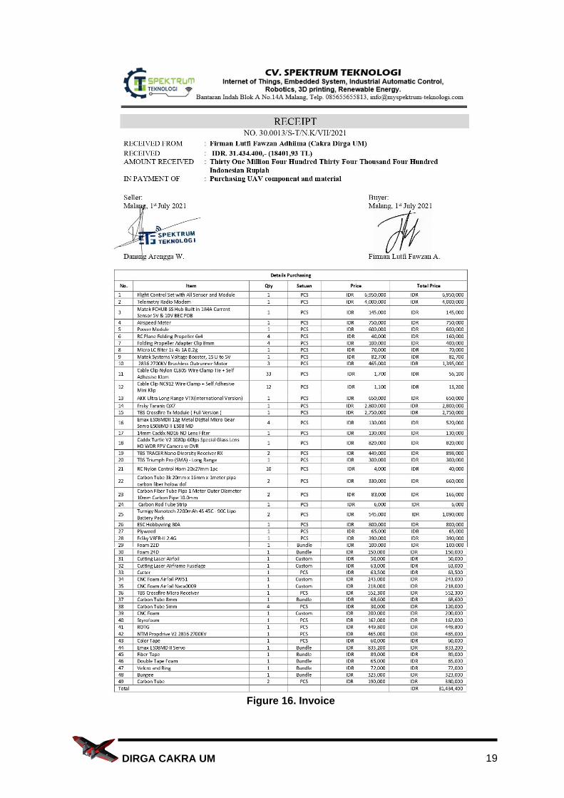
19 DIRGA CAKRA UM
Figure 16. Invoice
20 DIRGA CAKRA UM
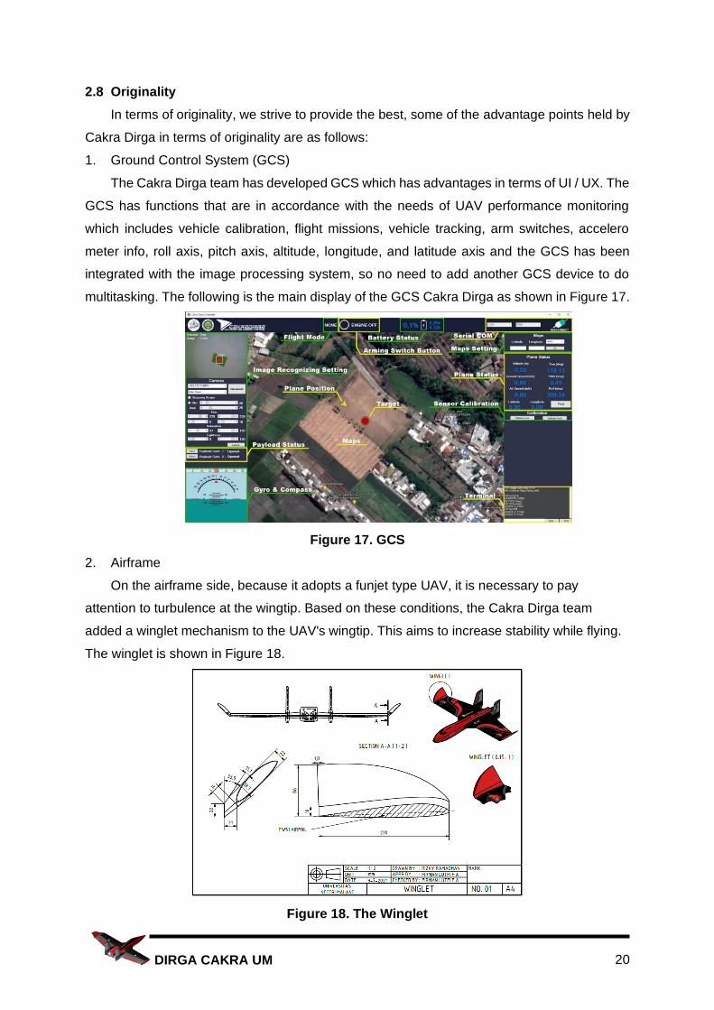
2.8 Originality
In terms of originality, we strive to provide the best, some of the advantage points held by
Cakra Dirga in terms of originality are as follows:
1. Ground Control System (GCS)
The Cakra Dirga team has developed GCS which has advantages in terms of UI / UX. The
GCS has functions that are in accordance with the needs of UAV performance monitoring
which includes vehicle calibration, flight missions, vehicle tracking, arm switches, accelero
meter info, roll axis, pitch axis, altitude, longitude, and latitude axis and the GCS has been
integrated with the image processing system, so no need to add another GCS device to do
multitasking. The following is the main display of the GCS Cakra Dirga as shown in Figure 17.
Figure 17. GCS
2. Airframe
On the airframe side, because it adopts a funjet type UAV, it is necessary to pay
attention to turbulence at the wingtip. Based on these conditions, the Cakra Dirga team
added a winglet mechanism to the UAV's wingtip. This aims to increase stability while flying.
The winglet is shown in Figure 18.
Figure 18. The Winglet