international workshop on interlocking concrete pavements
TRANSCRIPT

International Workshop on Interlocking Concrete Pavements
Session 7: Design for Heavy Duty Applications
International Workshop on Interlocking Concrete Pavements
THE STRUCTURAL DESIGN OF HEAVY DUTY CONCRETE BLOCK PAVEMENTS
J. Knapton, Nigel Dixon, Knapton & Partners, U.K.
See also papers by B. Shackel in Session 3 and R.S. Rollings in Session 5.

WORKSHOP ON INTERLOCKING CONCRETE PAVEMENTS 187
THE STRUCTURAL DESIGN OF HEAVY DUTY CONCRETE BLOCK PAVEMENTS
J. KNAPTON, B.Sc., Ph.D., MICE, MIHE, FFB, C.Eng., Nigel Dixon, Knapton and Partners, England.
ABSTRACT
This paper presents the background to the British Ports Association (BPA) industrial pavement design manual as it relates to concrete block paving. The paper describes the method of analysis used in the manual and the design criteria adopted. The range of pavements that can be designed and the material properties of these pavements ore described. The way in which industrial pavement loading is assessed is described and the concepts of the Port Area Wheel Load (PAWL) and Load Classification Index (LCI) are defined. The design of overlays is explained and material conversion factors are tabulated for all commonly used U.K. pavement construction materials. Design examples are presented for both new pavements and pavement strengthening. Conclusions are drawn regarding the advances in pavement design brought about by the development of the BPA pavement design method.
INTRODUCTION
In 1982 the British Ports Association (BPA) published the first manual directed towards the design of pavements subjected to very heavy industrial loading (Knapton 1982 and 1983). In 1983 the manual was enlarged to include a chapter dealing with pavement strengthening. The manual was produced in response to a concern felt by many that other pavement design methods, principally the Road Note 29 method (TRRL 1970), did not reflect the increasingly common use of very heavy cargo handling plant. Most of the procedures in Road Note 29 relate to a 'standard axle' of 8.2 t load, although one section does allow for extrapolation to 18 t axle loads.
In recent years, cargo handling plant has grown more sophisticated, more powerful and heavier, so that axle loads of 90 t are common and the dynamic magnification factors are significant. Although aircraft pavement design manuals (e.g. U.K. Department of the Environment 1971; U.S. Department of Transportation 1978) deal with heavy loads, patterns of aircraft movement and aircraft dynamics are considered to be sufficiently different from those of industrial plant to render those manuals inappropriate for use by the industrial pavement designer on a day-to-day basis.
However, it was considered that some features of the U.K. aircraft pavement design manual could be applied in the BPA publication. In particular, the Load Classification Number (LCN) concept, which assigns a numeric value to the pavement damaging effects of all types of aircraft, was considered to be transferrable to industrial pavements. Consequently, the BPA method classifies all industrial handling plant according to a Load Classification Index (LCI) system so that any plant item, or any system of cargo storage, can be assigned a letter between A, indicating light traffic, to H, indicating particularly severe loading. In the industrial paving context, LCI=A equates with highway loading, so it can be seen that the manual is concerned principally with a spectrum of loading ranging from highway loads (8.2 t axles) to 100 t axle loads.
This paper explains the background to the BPA manual, shows the properties of materials adopted and gives examples of pavement course thickness selection. Examples are shown both for new pavement design and for strengthening existing paving.
The particular relevance of the BPA manual to concrete block paving is that, for the first time, a design method is available which considers concrete block paving alongside other pavement surfacing materials. The manual was

188 WORKSHOP ON INTERLOCKING CONCRETE PAVEMENTS
produced by a trade association of pavement users rather than an organisation whose income is derived from concrete blocks. Also, it can deal with very heavy loads and it shows how to upgrade pavements under high load conditions. Concrete block paving has become a major material in heavy duty industrial paving throughout Europe and is now being also used in the U.S. and Australia.
CATEGORIES OF PAVEMENT INCLUDED
The manual has design charts for the four categories of pavement shown in Fig. I. There are two flexible pavements and two rigid pavements. The former are surfaced in either concrete paving blocks or bituminous material and both have lean concrete as the base. It will often be the case,
however, that the base will comprise a material other than lean concrete, and the manual shows how to deal with various base materials. The two rigid pavements comprise lightly-reinforced concrete and precast concrete rafts bedded in sand. Unsurfaced pavements are not considered, although it is recognised that such pavements frequently constitute a cost-effective solution requiring some regular maintenance. It is felt that the design of such pavements requires knowledge of local materials and is outside the scope of the manual.
Only scant attention is paid to surfacing material properties because the manual is concerned principally with structural design and not with material specification. In heavy duty paving, the surfacing contributes relatively little to the overall strength of the pavement, since the base is very thick and provides most of the pavement's strength.
MI - •z-7-:-..,-.;';°'..- idi
law Oils/ .
al t k 1 arr. ili i s
at Ai 0
Precast concrete rafts bedded in sand
Granular sub-base material
Subgrade
Precast concrete blocks bedded in sand
Lean concrete
Granular sub-base
Subgrade
Rigid pavement quality concrete
Granular sub-base
Subgrade
Asphalt
Lean concrete
Granular sub-base
Subgrade
Fig. I - Four categories of pavement

WORKSHOP ON INTERLOCKING CONCRETE PAVEMENTS 189
DESIGN PRINCIPLES
The fundamental design principle is to ensure that the designed pavement remains servicable while a specified loading regime is applied. Servicability failure in a heavy duty pavement occurs either by the development of excessive vertical compressive strain in the subgrade or by the development of excessive horizontal tensile strain in the base. Fig. 2 shows the location of these critical strains in each of the four categories of pavement. The allowable subgrade vertical compressive strain (Ev) adopted is given by:
EV = 1 2 600/N 0.28
where Ev is in microstrain and N is the number of repetitions of applied load.
For example, if the pavement were subjected to one load repetition, a strain of 21,600 microstrain, or 0.0216 strain, would be the maximum allowable, but if there were 10,000 repetitions, then the allowable strain would be only 1638 microstrain. This strain criterion is based upon a back-analysis of Road Note 29 designs undertaken by Brown (1974) and is more conservative than relationships proposed by Edwards and Valkering (1974) and Dorman and Metcalf (1978). Fig. 3 illustrates the relationship adopted, together with the two less conservative relationships.
Tensile strain
Compressive strain
Tensile strain
Compressive strain
Tensile strain
Compressive strain
Tensile strain
Compressive strain
Fig. 2 - Strains in four categories of pavement

300
Vertical Subgrade Strain 500
(x 10-6 ) 400
Dorman and Metcalf
fc characteristic compressive strength of base 1 - V2
material (MPa), and
190
WORKSHOP ON INTERLOCKING CONCRETE PAVEMENTS
1600-
1000 Edwards and Valkering
Brown (RN29) and BPA Manual
200
1 00 105 106 107
108
Number of Load Repetitions (allowable subgrade strain)
Fig. 3 - Allowable subgrade strain relationships
The maximum permitted horizontal tensile strain is given by the following equation, which was first proposed by Odemark (1977) and used as a design criterion in the Shell (1978) Pavement Design Manual:
fc
x 993,500
Eh =
6 x Eb1022
x N0.0502
where:
Eh = allowable base horizontal radial strain (microstrain),
the two critical locations when subjected to surface loading. The actual strains are determined by an analysis technique in which each course within the pavement is transformed into an equivalent thickness of the pavement's subgrade material. This transformation is based upon the concept that if an actual pavement course is replaced by a course of a different material and different thickness, then provided that the actual course and the transformed course have similar flexural stiffness, an accurate pavement analysis can be performed (see Ullidtz and Peattie 1980). For two courses of material to have similar flexural stiffness, the following term must be similar for each course:
h3 x E
N number of repetitions of applied load. where E is the elastic modulus, h is the course thickness and V is the Poisson's ratio.
When fc is less than 7 MPa, Eb = 4000 x fc, and
when fc is greater than 7 MPa, Eb = 16,800 x fc0•25.
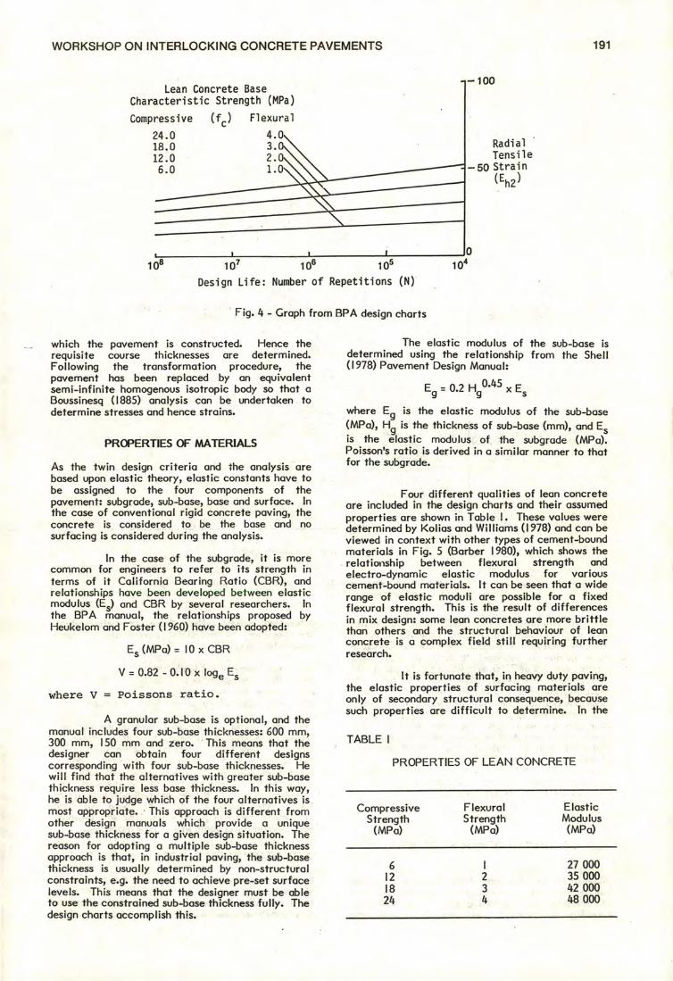
Fig. 4 shows the ralationship between Eh and N for four values of fc. This Figure is included
in each of the BPA design charts and is used in the examples presented later in this paper.
ANALYSIS TECHNIQUE
In order to determine whether a proposed pavement meets the two servicability criteria, it is necessary to determine the actual strains in the pavement at
Thus a course of thickness hi, elastic modulus E1 and Poisson's ratio V 1 can, in analytical terms, be replaced by a thickness h2 of a different material of elastic modulus E2 and Poisson's ratio V2 by:
3 x (1 - V2 2 )
2 x (1 - V
12 )
When each course of the pavement has been transformed, strains are calculated at the boundary of each course and these strains are compared with the limiting strains for the actual material from
(fc) Flexural
4.0 3.0 2.0 1.0
Compressive
24.0 18.0 12.0 6.0
Radial Tensile
—50 Strain
(Eh2 )
Lean Concrete Base Characteristic Strength (MPa)
—100
0
WORKSHOP ON INTERLOCKING CONCRETE PAVEMENTS 191
108 107 106 105
io4 Design Life: Number of Repetitions (N)
Fig. 4 - Graph from BPA design charts
which the pavement is constructed. Hence the requisite course thicknesses are determined. Following the transformation procedure, the pavement has been replaced by an equivalent semi-infinite homogenous isotropic body so that a Boussinesq (1885) analysis can be undertaken to determine stresses and hence strains.
PROPERTIES OF MATERIALS
As the twin design criteria and the analysis are based upon elastic theory, elastic constants have to be assigned to the four components of the pavement: subgrade, sub-base, base and surface. In the case of conventional rigid concrete paving, the concrete is considered to be the base and no surfacing is considered during the analysis.
In the case of the subgrade, it is more common for engineers to refer to its strength in terms of it California Bearing Ratio (CBR), and relationships have been developed between elastic modulus (Es) and CBR by several researchers. In the BPA manual, the relationships proposed by Heukelom and Foster (1960) have been adopted:
Es (MPa) = 10 x CBR
V = 0.82 - 0.10 x loge Es
where V = Poissons ratio.
A granular sub-base is optional, and the manual includes four sub-base thicknesses: 600 mm, 300 mm, 150 mm and zero. This means that the designer can obtain four different designs corresponding with four sub-base thicknesses. He will find that the alternatives with greater sub-base thickness require less base thickness. In this way, he is able to judge which of the four alternatives is most appropriate. This approach is different from other design manuals which provide a unique sub-base thickness for a given design situation. The reason for adopting a multiple sub-base thickness approach is that, in industrial paving, the sub-base thickness is usually determined by non-structural constraints, e.g. the need to achieve pre-set surface levels. This means that the designer must be able to use the constrained sub-base thickness fully. The design charts accomplish this.
The elastic modulus of the sub-base is determined using the relationship from the Shell (1978) Pavement Design Manual:
Eg = 0.2 H /145 x Es
where E is the elastic modulus of the sub-base
(MPa), Hg is the thickness of sub-base (mm), and Es is the elastic modulus of the subgrade (MPa). Poisson's ratio is derived in a similar manner to that for the subgrade.
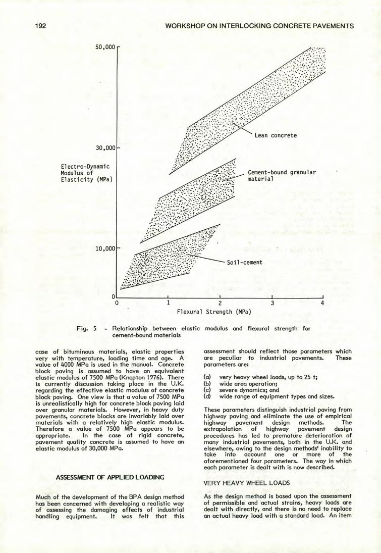
Four different qualities of lean concrete are included in the design charts and their assumed properties are shown in Table I. These values were determined by Kolias and Williams (1978) and can be viewed in context with other types of cement-bound materials in Fig. 5 (Barber 1980), which shows the relationship between flexural strength and electro-dynamic elastic modulus for various cement-bound materials. It can be seen that a wide range of elastic moduli are possible for a fixed flexural strength. This is the result of differences in mix design: some lean concretes are more brittle than others and the structural behaviour of lean concrete is a complex field still requiring further research.
It is fortunate that, in heavy duty paving, the elastic properties of surfacing materials are only of secondary structural consequence, because such properties are difficult to determine. In the
TABLE I
PROPERTIES OF LEAN CONCRETE
Compressive Strength
(MPa)
6
27 000
12
2
35 000
18
3
42 000
24
4
48 000
Flexural
Elastic Strength
Modulus (MPa)
(MPa)
Electro-Dynamic Modulus of Elasticity (MPa)
Cement-bound granular material
0 0
I I 3 4 1 2
Flexural Strength (MPa)
50,000
Lean concrete
30,000
10,000
Soil-cement
192 WORKSHOP ON INTERLOCKING CONCRETE PAVEMENTS
Fig. 5 - Relationship between elastic modulus and flexural strength for cement-bound materials
case of bituminous materials, elastic properties very with temperature, loading time and age. A value of 4000 MPa is used in the manual. Concrete block paving is assumed to have an equivalent elastic modulus of 7500 MPa (Knapton 1976). There is currently discussion taking place in the U.K. regarding the effective elastic modulus of concrete block paving. One view is that a value of 7500 MPa is unrealistically high for concrete block paving laid over granular materials. However, in heavy duty pavements, concrete blocks are invariably laid over materials with a relatively high elastic modulus. Therefore a value of 7500 MPa appears to be appropriate. In the case of rigid concrete, pavement quality concrete is assumed to have an elastic modulus of 30,000 MPa.
ASSESSMENT OF APPLIED LOADING
Much of the development of the BPA design method has been concerned with developing a realistic way of assessing the damaging effects of industrial handling equipment. It was felt that this
assessment should reflect those parameters which are peculiar to industrial pavements. These parameters are:
(a) very heavy wheel loads, up to 25 t; (b) wide area operation; (c) severe dynamics; and (d) wide range of equipment types and sizes.
These parameters distinguish industrial paving from highway paving and eliminate the use of empirical highway pavement design methods. The extrapolation of highway pavement design procedures has led to premature deterioration of many industrial pavements, both in the U.K. and elsewhere, owing to the design methods' inability to take into account one or more of the aforementioned four parameters. The way in which each parameter is dealt with is now described.
VERY HEAVY WHEEL LOADS
As the design method is based upon the assessment of permissible and actual strains, heavy loads are dealt with directly, and there is no need to replace an actual heavy load with a standard load. An item

WORKSHOP ON INTERLOCKING CONCRETE PAVEMENTS 193
of plant is assigned a damage rating in the following way. For each wheel on one side of the plant, the damaging effect is calculated using the equation:
) 3.75 ( p ) 1.25
D= x — (2,000 0.8
where D is the pavement damage, W is the wheel load (kg), and P is the tyre pressure (MPa).
This equation employs the fourth power damage rule proposed by Odemark (1949), which is a statement of the relative sensitivity of pavement damage to applied load, applied pressure and the number of repetitions of the load and the pressure. The equation gives pavement damage, D, in units which were devised during the development of the BPA design manual. This unit is the Port Area Wheel Load (PAWL), and the damaging effect of one PAWL is defined as the damage inflicted on a pavement by one repetition of a 12 t wheel load applying a contact pressure of 0.8 MPa (800 kPa). For each wheel on one side of the plant (some items of plant have different wheel loads on each side, in which case use the heavier side), the PAWLs are assessed and the plant is assigned a Load Classification Index (LCI) according to the relationship shown in Table 2. An LCI of A indicates a relatively undamaging item of plant; conventional highway vehicles fall into this category. The LCI boundaries have been chosen so that the heaviest materials-handling plant in current use fall within categories F, G and H, depending on how they are operated.
TABLE 2
RELATIONSHIP BETWEEN PORT AREA WHEEL LOAD (PAWL) VALUES
AND LOAD CLASSIFICATION INDEX (LCI)
PAWL Value LCI
Less than 2
A 2-4
B 4-8
C 8-16
D 16-32
E 32-64
F 64-128 128-256
H
WIDE AREA OPERATION
The relationship between vehicle track width and the effective lane width within which it operates governs the number of repetitions to which an isolated point in a pavement is subjected. Therefore, when assessing the number of repetitions for which a pavement should be designed, a reduction of total lane movements is undertaken as follows.
(a) When the effective lane width is greater than 5.5 times the track width, only one-third of movements are considered to occur over one point.
(b) When the effective lane width is between 5.5 and 3 times the track width, one-half of the movements are taken for design.
(c) When the effective lane width is less than 3 times the track width, the number of design repetitions is equal to the number of movements.
These reductions are based upon observations of the lateral distribution of moving plant in lanes of different width.
SEVERE DYNAMICS
In assessing the PAWL value for each wheel, it is necessary to assume a wheel load, W (kg). This load should take into account the effect of mass transfer induced by dynamics. Dynamic factors have been defined and static wheel loads are multiplied by these factors prior to PAWL calculations. Table 3 shows the dynamic factors adopted for various generic types of plant and for various operating conditions. Where two or three operating conditions apply simultaneously, the dynamic factors should be multiplied together prior to static load multipication.
It should be noted that the effect of dynamics is particularly severe and the factors should be applied simultaneously only where there is specific reason to do so. Dynamic factors can affect thickness by up to 50 per cent. Where vehicle movements can be pre-determined, it will be possible to design substantial areas of the pavement with dynamic effects.
The values in Table 3 were determined from three sources. Manufacturers of handling equipment supplied values for front lift trucks, straddle carriers and side loaders. In the case of tractor and trailer systems, there were no reliable data available. The problem was discussed at five meetings of U.K. port engineers during the development of the design procedure and the values are concensus ones. A third source was the manufacturers of industrial vehicle tyres.
The way in which tyres deform under transient loading has a major influence on the damage sustained by the upper courses of a pavement. Two extremes are a totally flexible tyre and a fully rigid one. In the flexible case, a transient load increase deforms the tyre in such a way that the contact stress remains constant and the contact area increases. With a rigid tyre, a transient load increase has no effect on tyre shape, but increases the contact stress. All tyres fall between these two extremes but vary considerably in their stiffness. Dynamic effects are olso influenced by tread pattern, wheel alignment and steering geometry, and all are difficult to quanitify.
It is felt that an investigation into handling equipment dynamics would constitute a worthwhile research project which may lead to minor changes in the figures in Table 3. The design method has been formulated in such a way that such changes can be easily implemented.

194 WORKSHOP ON INTERLOCKING CONCRETE PAVEMENTS
TABLE 3
DYNAMIC FACTORS FOR DIFFERENT CATEGORIES OF PLANT
Type of Plant Type of Operation
Braking
Cornering Accelerating Uneven Surface
Front lift trucks 1.3 1.4 1.1 1.2 Straddle carriers 1.5 1.6 1.1 1.2 Side lift trucks 1.2 1.3 1.1 1.2 Tractors & trailers 1.1 1.3 1.1 1.2
EQUIPMENT TYPES AND SIZES
Because the design method is based upon fatigue-oriented elastic analysis, it is not limited to any particular class of plant. Even equipment which has yet to be developed could be classified relatively easily. A factor that is also taken into account is wheel proximity. The addition of strains attributed to closely-spaced wheels produces a significant increase in pavement thickness for certain types of plant, e.g. front lift trucks with two or three wheels at each end of their front axle. For wheels bolted side by side, the two or three wheels are considered to be a single wheel of load equal to their sum. For wheels in tandem, Table 4 shows proximity factors by which PAWL values for individual wheels are multiplied prior to addition to determine the LCI. The factors in Table 4 are dependent both on longitudinal wheel spacing and, to a lesser sensitivity, on the plant's PAWL value.
The author has undertaken a study of the superposition of strains at critical depths beneath pavements and has found this approach to be satisfactory, producing errors no greater than 5 per cent.
OVERLAY DESIGN
In many industrial situations, a particularly relevant problem is that of strengthening an existing
TABLE 4
pavement. An existing pavement may be showing signs of distress, or the operator may purchase new and more damaging plant that the existing pavement will not support. In these situations, the engineer will require a pavement design method which takes account of the residual strength of the existing pavement and which allows him to design an overlay comprising one or more courses of a new material. The strengthened pavement should act as a coherent structure if full advantage of the residual strength of the existing pavement is to be gained.
Overlying distressed pavements is of particular relevance to concrete block paving since concrete blocks can frequently be used to overlay badly cracked or deformed rigid and flexible paving, whereas other overlay materials can be used only when the existing pavement is still in reasonably good condition.
It is important to recognise a difference in approach between highway authorities and industrial pavement managers with respect to deciding when to overlay pavements. In the case of highway authorities, a monitoring system, usually involving the measurement of pavement deflection, is used to assess the appropriate time to overlay so as to avoid damaging the roadbase. The industrial pavement manager waits until potholes have formed or reinforcement is exposed and has become a hazard to pedestrians or tyres. For this reason, concrete block paving finds wide application in overlying industrial pavements.
PROXIMITY FACTORS FOR VARIOUS LONGITUDINAL WHEEL SPACINGS AND VARIOUS PAWL VALUES
Longitudinal Wheel
Spacing (mm)
Proximity Factors for Various Damaging Effects
2 4 8 16 32 64 128 256 PAWL PAWL PAWL PAWL PAWL PAWAL PAWL PAWL
500 1.94 1.95 1.96 1.96 1.97 1.98 1.98 1.98
1000 1.80 I.84 1.85 1.86 1.87 1.89 1.92 1.93
2000 1.40 1.45 1.51 1.58 1.62 1.64 1.72 1.75
4000 1.00 1.01 1.05 1.09 1.14 1.21 1.28 1.33

As new 1.0 Slight cracking 0.8 Substantial cracking 0.5 Fully cracked or
crazed and spoiled 0.2
0 to 10
1.0 II to 20
0.9 21 to 40
0.6 40 +
0.3
WORKSHOP ON INTERLOCKING CONCRETE PAVEMENTS 195
The first stage in the design of an overlay is to assess the strength of the existing pavement. To do this, information should be obtained from construction records supplemented by taking cores throughout the area. The thickness and condition of each existing course is transformed into an equivalent thickness of 12 MPa lean concrete. The actual thickness of each course is multiplied by a constant taken from Table 5. The factors in Table 5 are a measure of the ratio of the strength of the material concerned to the strength of lean concrete.
Account must also be taken of the less than perfect condition of each course of the existing pavement. This is assomplished by multiplying Ilie equivalent thickness by two condition factors, CFI and CF2. Factor CFI applies an equivalent thickness reduction for
TABLE 5
cracked areas. The values of CFI and CF2 are shown in Tables 6 and 7.
When the factors in Tables 5, 6 and 7 have been applied to each course of the pavement, the result is a thickness of 12 MPa lean concrete to which the existing pavement is equivalent. Secondly, the BPA charts can be used to determine how much 12 MPa lean concrete is required for strengthened pavements. The difference between that required and that currently existing is the amount to be provided. This does not constrain the designer to use 12 MPa lean concrete as the strengthening material, since when he has evaluated the thickness of this material required, he can return to Table 6 and determine the thickness of any of the other bound materials he may prefer to use.
MATERIAL CONVERSION FACTORS FOR COMPONENT ANALYSIS METHOD
Type of Material
Material Conversion
Factor
12 MPa lean concrete
1.0 18 MPa lean concrete
1.3
30 MPa pavement quality concrete
1.7 Cement-bound granular material
0.7
Soil cement
0.5 130 mm concrete block paving including 50 mm sand
Concrete raft units (2 m x 2 m)
1.5 Open-textured bituminous material stiffened with latex slurry
1.5
Dense bituminous macadam
1.0 Rolled asphalt
0.8 Wetmix macadam
0.4 Dry-bound macadam
0.4 Type I sub-base material over
subgrades with CBR > 5%
0.3 Type I sub-base material over
subgrades with CBR -5 5%
0.2 Type 2 sub-base material over
subgrades with CBR > 5%
0.2 Type 2 sub-base material over
subgrades with CBR < 5%
0.1 Subgrade
0.0
TABLE 6
CONDITION FACTORS FOR CRACKING AND SPALLING
Condition of Material CFI
TABLE 7
CONDITION FACTORS FOR MAXIMUM DEGREE RUTTING
AND SETTLEMENT
Degree of Localised CF2 Rutting or Settlement (mm)

196 WORKSHOP ON INTERLOCKING CONCRETE PAVEMENTS
NEW PAVEMENT DESIGN EXAMPLE
Assume a front lift truck (FLT) is handling 40 ft (12.2 m) laden containers and connering has to be considered.
Unladen weight of FLT: 50.5 t Contact stress (assumed to be
working tyre pressure): 700 kPa Dynamic factor: 1.4 Critical container weight: 23 t Lane width: 5 m Plant track width: 3.3 m
LCI calculations show this item of plant to have a LCI of G.
CBR of subgrade: Cumulative number of load
repetitions: Lane width factor:
The relevant design charts can be used to obtain the solutions shown in Table 8. Three types of pavement are designed: asphalt, concrete blocks and rigid concrete. For each type, three thicknesses of sub-base are shown. As already mentioned, one of the features of the design method is that it provides three sub-base thicknesses, so that the engineer can select the appropriate sub-base thickness and use the corresponding base thickness.
OVERLAY DESIGN
An existing pavement comprises the materials shown in Fig. 6a. It was originally designed to withstand straddle carriers of LCI value B. The pavement is in good condition except for 15 mm ruts, which occur only in the asphalt surface course. It is proposed to replace the straddle carrier with a front lift truck (FLT) of LCI value G. The most severely trafficked part of the pavement will carry 200 passes per day of the laden FLT and the strengthened pavement is required to last a further 12 years, each with 300 working days.
Number of FLT repetitions = 200 x 300 x 12 = 720,000 cumulative passes.
TABLE 8
Using the relevant BPA chart for 5 per cent subgrade CBR and a 300 mm thick sub-base with asphalt surface, the pavement shown in Fig. 6b is shown to be required, i.e. if a new pavement were being designed for the FLT, it would be as shown in Fig. 6b. The residual effective thickness of the existing rutted pavement is 397 mm of 12 MPa lean concrete. Table 9 shows how Tables 5, 6 and 7 are used to determine this thickness. Therefore the thickness of 12 MPa lean concrete required in the overlay is 500 mm - 397 mm = 103 mm, say 100 mm.
The strengthened pavement is shown in Fig. 6u, in wliiuli 12 MPu leuu Lunt,' ete is uctually used as the overlay structural material. If required, an alternative material could be used in which the material conversion factors shown in Table 5 are used to determine the thickness of the alternative material required. For example, if wetmix macadam was used, the required thickness would be 103/0.4, i.e. 257 mm (0.4 is the material conversion factor for wetmix macadam in Table 5).
CONCLUSIONS
For both new pavement design and overlay design, the British Ports Association pavement design method represents a significant contribution to the design of industrial pavements. It is the first structured design method to take into account many of the factors involved in industrial handling situations which contribute to pavement deterioration. In particular, it ensures that loading is considered in a realistic way in that actual loads, including dynamic effects, are used rather than standard loads. It is also unique in that it provides designs with alternative sub-base thicknesses so that the most appropriate combination of base and sub-base thickness can be selected to ensure a cost-effective solution.
Possibly the most valuable aspect of the design method is its ability to deal with pavement strengthening situations. Hitherto, the problem of strengthening an existing, possibly dilapidated pavement subjected to loads substantially greater than highway loading, has been a major problem.
7%
1.5 x 10⁶
1.0
DESIGN SOLUTIONS FOR LARGE FLT TRANSPORTING LADEN 40 ft (12.2 m) CONTAINERS; PAVEMENT CONSTRUCTED
OVER 7% CBR SUBGRADE
Type of Base Thickness (mm)
Sub-base Pavement (18 MPa lean concrete)
Thickness (mm)
Asphalt 410 150 390 300 370 600
Concrete 400 150 blocks 380 300
360 600
Rigid 390 150 concrete 370 300
350 600

(a) EXISTING PAVEMENT
Blocks
Lean concrete (12 MPa)
Type 1 granular sub-base
130
T
500
• • 4 4 .',4 ', •
300
\z/
WORKSHOP ON INTERLOCKING CONCRETE PAVEMENTS 197
:117)03%;Wkimolk.irierAeg Asphalt
Lean concrete (18 MPa)
Type 1 granular sub-base
5% CBR subgrade
100
250
300
5% CBR subgrade (b) REQUIRED PAVEMENT
I •L I I- i T 1 . :. -.51,..*.p.,,,,;:tiv;.,i,
- e..?•,,,,i, 'V; -xi*.Srt '`.01.04.&1:±AV;;;.
A: :• ••4.1.:--* • . ' .'§: -:.....7,<S;',
nti 0 r--7/ / /—\L -C
130••
100 10D*
250
300
Blocks
Lean concrete (12 MPa)
Asphalt
Lean concrete (18 MPa)
Type 1 granular sub-base
5% CBR subgrade
(c) STRENGTHENED PAVEMENT
All dimensions in mm
Fig. 6 - Pavement section for overlay design example
TABLE 9
EFFECTIVE THICKNESS OF EXISTING PAVEMENT IN OVERLAY DESIGN EXAMPLE
Course
Actual
Material
Condition Factor Equivalent Thickness
Conversion
Thickness of
(mm)
Factor
12 MPa Lean CFI CF2 Concrete (mm)
Asphalt 100 0.8 1.0 0.9 72
18 MPa lean concrete
250 1.3 1.0 1.0 325
397
WORKSHOP ON INTERLOCKING CONCRETE PAVEMENTS 198
REFERENCES
BARBER, S.D. (1980). Pavement design for port areas. Ph.D. Thesis, Univ. Newcastle Upon Tyne.
BOUSSINESQ, J. (1885). Application det potentiels a l'etude de equilibre et du movement de solides elastique. Gauthier-Villars, Paris.
BROWN, S.F. (1974). A simplified fundamental design procedure for bituminous pavements. Highw. Eng. XXI(8/9), pp. 14-23.
DORMAN, G.M. and METCALF, C.T. (1978). Design curves for flexible pavements based on layered system theory. Highw. Res. Rec. 71.
EDWARDS, J.M. and VALKERING, C.P. (1974). Structural design of asphalt pavements for road vehicles - the influence of high temperature. Highw. Road Constr. 42, pp. 4-9.
HEUKELOM, V. and FOSTER,C.R. (1960). Dynamic testing of pavements. J. Soil Mech. Found. End. Div. Proc. ASCE 86(5M1), Paper 2368, pp. 1-28.
KNAPTON, J. (1976). The design of concrete block roads. Cement Conc. Assoc. U.K. Pub. 42.515.
(1982 and 1983). The structural design of heavy duty pavements for ports and other industries. British Ports Assoc., London.
KOLIAS, S. and WILLIAMS, R.I.T. (1978). Cement bound road materiels: strength and elastic properties measured in the laboratory. Transp. Road Res. Lab. (U.K.) TRRL Supp. Rep. SR 344.
ODEMARK, N. (1949). Undersokning av elasticitesegenskaperna has olika jordarter samp teori for berakning av belagningar enlight elasticitersteorien. Satens Vaqinstitut, Meddelande 77.
SHELL INTERNATIONAL PETROLEUM COMPANY LIMITED (1978). Pavement design manual.
TRANSPORT AND ROAD RESEARCH LABORATORY (1970). A guide to the structural design of pavements for new roads. Road Note 29.
ULLIDTZ, P. and PEATTIE, K.R. ( I 980). Pavement analysis by programmable calculator. Transp. Eng. J., September.
UNITED KINGDOM. DEPARTMENT OF THE ENVIRONMENT (1971). Design and evaluation of aircraft pavements. (HMSO: London.)
UNITED STATES. DEPARTMENT OF TRANSPORTATION (1978). Airport pavement design and evaluation. Fed. Aviation Admin., Washington DC.
John Knapton's practice, Nigel Nixon, Knapton & Partners of Newcastle upon Tyne and London specialises in heavy duty pavement design and concrete block paving. The practice was founded in 1980 after he left the University of Newcastle upon Tyne where he initiated the First International Conference on Concrete Block Paving in September 1980. He first became interested in concrete block paving in 1973 whilst working as a Research Engineer at the Cement and Concrete Association. He published the worlds first concrete block pavement design guide in 1976 and is the author of the British Ports Association design manual on heavy duty paving. He has published over 40 papers in the related fields of concrete block paving and heavy duty paving. In recent years, he has developed concrete block pavement projects for:
Port of London Authority, U.K. Port of Sunderland Authority, U.K. Dover Harbour Board, U.K. Portsmouth Harbour Commissioners, U.K. Forth Ports Authority, U.K. Thai Port Authority, Thailand Mina Sulman Port Authority, Bahrein San Fransisco Port Authority, U.S.A. Port of Portland, U.S.A. St. Johns Harbour Board, Canada Cork Harbour Board, Ireland British Transport Docks Board, Immingham, U.K.
He is a Chartered Civil Engineer and is a member of the Institution of Civil Engineers and the Institution of Highways and Transportation, having graduated from the University of Newcastle upon Tyne with a B.Sc. and a Ph.D. in Civil Engineering.