internet-draft taxonomy of coding techniques march 2018 · taxonomy of coding techniques for...
TRANSCRIPT

NWCRG B. AdamsonInternet-Draft NRLIntended status: Informational C. AdjihExpires: September 19, 2018 INRIA J. Bilbao Ikerlan V. Firoiu BAE Systems F. Fitzek TU Dresden S. Ghanem Independant E. Lochin ISAE - Supaero A. Masucci Orange M-J. Montpetit Independant M. Pedersen Aalborg University G. Peralta Ikerlan V. Roca, Ed. INRIA P. Saxena AnsuR Technologies S. Sivakumar Cisco March 18, 2018
Taxonomy of Coding Techniques for Efficient Network Communications draft-irtf-nwcrg-network-coding-taxonomy-08
Abstract
This document is the product of the Network Coding Research Group (NWCRG). It summarizes a recommended terminology for Network Coding concepts and constructs. It provides a comprehensive set of terms in order to avoid ambiguities in future IRTF and IETF documents on Network Coding. This document is in-line with the terminology used by the RFCs produced by the Reliable Multicast Transport (RMT) and FEC Framework (FECFRAME) IETF working groups.
Adamson, et al. Expires September 19, 2018 [Page 1]

Internet-Draft Taxonomy of Coding Techniques March 2018
Status of This Memo
This Internet-Draft is submitted in full conformance with the provisions of BCP 78 and BCP 79.
Internet-Drafts are working documents of the Internet Engineering Task Force (IETF). Note that other groups may also distribute working documents as Internet-Drafts. The list of current Internet- Drafts is at https://datatracker.ietf.org/drafts/current/.
Internet-Drafts are draft documents valid for a maximum of six months and may be updated, replaced, or obsoleted by other documents at any time. It is inappropriate to use Internet-Drafts as reference material or to cite them other than as "work in progress."
This Internet-Draft will expire on September 19, 2018.
Copyright Notice
Copyright (c) 2018 IETF Trust and the persons identified as the document authors. All rights reserved.
This document is subject to BCP 78 and the IETF Trust’s Legal Provisions Relating to IETF Documents (https://trustee.ietf.org/license-info) in effect on the date of publication of this document. Please review these documents carefully, as they describe your rights and restrictions with respect to this document. Code Components extracted from this document must include Simplified BSD License text as described in Section 4.e of the Trust Legal Provisions and are provided without warranty as described in the Simplified BSD License.
Table of Contents
1. Introduction . . . . . . . . . . . . . . . . . . . . . . . . 3 1.1. Requirements Language . . . . . . . . . . . . . . . . . . 4 2. General definitions and concepts . . . . . . . . . . . . . . 4 3. Taxonomy of Code Uses . . . . . . . . . . . . . . . . . . . . 7 4. Coding Details . . . . . . . . . . . . . . . . . . . . . . . 9 4.1. Coding Types . . . . . . . . . . . . . . . . . . . . . . 9 4.2. Coding Basics . . . . . . . . . . . . . . . . . . . . . . 10 4.3. Coding In Practice . . . . . . . . . . . . . . . . . . . 12 5. IANA Considerations . . . . . . . . . . . . . . . . . . . . . 13 6. Security Considerations . . . . . . . . . . . . . . . . . . . 13 7. References . . . . . . . . . . . . . . . . . . . . . . . . . 13 7.1. Normative References . . . . . . . . . . . . . . . . . . 13 7.2. Informative References . . . . . . . . . . . . . . . . . 13 Appendix A. Additional references . . . . . . . . . . . . . . . 14
Adamson, et al. Expires September 19, 2018 [Page 2]

Internet-Draft Taxonomy of Coding Techniques March 2018
Appendix B. Authors and Contributors . . . . . . . . . . . . . . 14 Authors’ Addresses . . . . . . . . . . . . . . . . . . . . . . . 14
1. Introduction
This document is not an IETF product and is not a standard. This document is the product and represents the consensus of the Network Coding Research Group (NWCRG). In 2017, it has been discussed during three audio conferences, each of them gathering 6 to 8 key experts, it has been co-edited, and finally subject to a RG Last Call. The general feeling was that the document was ready for the next step.
The literature on Network Coding research and system design, IETF included, led to a rich set of concepts and constructs. This document collects terminology used in the domain, both outside and inside IETF, provides concise definitions, and introduces a high- level taxonomy. Its primary goal is to be useful to IETF and IRTF activities. It is also in-line with the terminology already used by the RFCs produced by the Reliable Multicast Transport (RMT) and FEC Framework (FECFRAME) IETF working groups, in particular [RFC5052] [RFC5740] [RFC5775] [RFC6363] [RFC6726]. Note that in the definitions, the "(IETF)" tag indicates that the associated term is already used in IETF documents.
This document focuses on packet transmissions and packet losses. These losses will typically be triggered by various types of networking issues and/or impairments (e.g., congested routers or intermittent wireless connectivity). The notion of "packet" itself is multiform, depending on the target use-case and the notion of network (e.g., in which layer of the protocol stack does the coding middleware operate?). For instance, a "packet" may be a data unit to be carried as a UDP payload because the coding middleware is located between the application and UDP. In another configuration, coding may be applied within an overlay network and the notion of "packet" will be totally different. In any case the goals of Network Coding can be to improve the network throughput, efficiency, latency, and scalability, as well as providing resilience to partition, attacks, and eavesdropping (NWCRG charter). Both End-to-End Coding and systems that also perform re-coding within intermediate forwarding nodes are considered in this document.
This document does not consider physical layer transmission issues, nor physical layer codes, nor error detection: if low layer error codes detect but fail to correct bit errors, or if an upper layer checksum (e.g., within IP or UDP) identifies a corrupted packet, then this packet is supposed to be dropped.
Adamson, et al. Expires September 19, 2018 [Page 3]

Internet-Draft Taxonomy of Coding Techniques March 2018
1.1. Requirements Language
The keywords "MUST", "MUST NOT", "REQUIRED", "SHALL", "SHALL NOT", "SHOULD", "SHOULD NOT", "RECOMMENDED", "MAY", and "OPTIONAL" in this document are to be interpreted as described in RFC 2119 [RFC2119].
2. General definitions and concepts
This section gathers general definitions and concepts that are used throughout this document.
Packet Erasure Channel: A communication path where packets are either dropped or received without any error. This type of packet drop is referred to as an "erasure" or "loss". The term "channel" must be understood as a generic term for any type of communication technology (e.g., an Ethernet link, a WiFi network, or a full path between two nodes over the Internet). The "Erasure" channels are opposed to "Error" channels where one or multiple bit errors may happen during a packet transmission. These "Error" channels are out of scope.
Erasure Correcting Code (ECC), or (IETF) Forward Erasure Code (FEC):
A code for the Packet Erasure Channel (only). These codes are also called "Application-Level FEC" to highlight that they have been designed to be used within the higher layers of the protocol stack, to protect against packet losses. These codes are opposed to "Error" correction codes that are capable of identifying the presence and/or correcting bit errors. The "Error" correction codes are out of scope.
End-to-End Coding: A system where coding is performed at the source or (coding) middlebox, and decoding at the destination(s) or (decoding) middlebox. There is no re- coding operation at intermediate nodes. This is the approach followed in the FLUTE/ALC [RFC6726][RFC5775], NORM [RFC5740] and FECFRAME [RFC6363] protocols.
Network Coding: A system where coding can be performed at the source as well as at intermediate forwarding nodes (all or a subset of them). End-to-End Coding is regarded as a special case of Network Coding. Depending on the use case, additional assumptions can be made: for instance the knowledge by the destination of the coding nodes topology and coding operations can help during decoding operations.
Adamson, et al. Expires September 19, 2018 [Page 4]

Internet-Draft Taxonomy of Coding Techniques March 2018
Packet versus Symbol: Generally speaking, a Packet is the unit of data that is sent in the Packet Erasure Channel, while a Symbol is the unit of data that is manipulated during the encoding and decoding operations.
Original Payload, or Uncoded Payload, or Systematic Symbol, or (IETF) Source Symbol: A unit of data originating from the source that is used as input to encoding operations. When there is a single Source Symbol per Source Packet, an Original Payload corresponds to a Source Packet.
Coded Payload, Coded Symbol, or (IETF) Repair Symbol: A unit of data that is the result of a coding operation, applied either to Source Symbols or (in case of recoding) Source and/or Repair Symbols. When there is a single Repair Symbol per Repair Packet, a Coded Payload corresponds to a Repair Packet.
Input Symbol and Output Symbol: A unit of data that is used as input to an encoding operation or that is generated as output of an encoding operation. At a re-coding node, Repair Symbols are also part of the Input Symbols. With Systematic Coding, Source Symbols are also part of the Output Symbols.
(IETF) Encoding Symbol: A Source or a Repair Symbol.
(En)coding versus Recoding versus Decoding: (En)coding is an operation that takes Source Symbols as input and produces Encoding Symbols as output. Recoding is an operation that takes Encoding Symbols as input and produces Encoding Symbols as output. Decoding is an operation takes Encoding Symbols as input and produces Source Symbols as output.
(IETF) Source Packet: A packet originating from the source which contributes to one or more Source Symbols. For instance, an RTP packet as a whole can constitute a Source Symbol. In other situations (e.g, to address variable size packets) a single RTP packet may contribute to various Source Symbols.
(IETF) Repair Packet: A packet containing one or more Repair Symbols.
Figure 1 illustrates the relationships between packets (what is sent in the Packet Erasure Channel) and symbols (what is manipulated
Adamson, et al. Expires September 19, 2018 [Page 5]

Internet-Draft Taxonomy of Coding Techniques March 2018
during encoding and decoding operations) in case of FEC encoding, at a Coding Node that performs Encoding (rather than Recoding). FEC decoding procedures are similarly performed in the reverse order.
source packet | | source packet to source symbols transform | (one or more symbols per packet) v source symbols | v input symbols +----------------------+ | FEC encoding | +----------------------+ | output symbols | v v source symbols repair symbols | | | | symbol to packet transform | | (one or more symbols per packet) v v source packet repair packet
Figure 1: Packet and symbol relationships at a Coding Node that performs Encoding (rather than Recoding).
Source Node: A node that generates one or more Source Flows.
Coding Node: A node that performs FEC Encoding or Recoding operations. It may be an end-host or a middlebox (Encoding case), or a forwarding node (Recoding case).
(IETF) Flow: A stream of packets logically grouped.
(IETF) Source Flow: A flow of Source Packets coming from an application on a given host, and to which FEC encoding is to be applied, potentially along with other Source Flows. Depending on the use case, Source Flows may come from the same application, from different applications on the same host, or from different applications on different hosts.
(IETF) Repair flow: A flow containing Repair Packets, after FEC encoding.
Adamson, et al. Expires September 19, 2018 [Page 6]

Internet-Draft Taxonomy of Coding Techniques March 2018
3. Taxonomy of Code Uses
This section discusses the various ways of using coding, without going into coding details.
Source Coding versus Channel Coding: (see Figure 2) When both terms are opposed, "Source Coding" usually refers to compression techniques (e.g., audio and video compression) within the upper application that generates the source flow. On the opposite, "Channel Coding" refers to FEC encoding in order to improve transmission robustness, for instance within the lower physical layer (out of scope of this document) or as part of Network Coding. These terms should not be confused with respectively "FEC coding within the Source Node" and "FEC re-coding within an intermediate Coding Node".
Adamson, et al. Expires September 19, 2018 [Page 7]

Internet-Draft Taxonomy of Coding Techniques March 2018
raw data flow from camera ^ video flow display | | ^ v | upper | +-----------------------+ | +-----------------------+ | source coding | | applica- | source (de)coding | |(e.g. mpeg compression)| | tion |(eg. mpg decompression)| +-----------------------+ v +-----------------------+ | ^ v | +-----------------------+ ^ +-----------------------+ | network/AL-FEC coding | | middle- | network/AL-FEC coding | | (e.g. RLC encoding) | | ware | (e.g. RLC decoding) | +-----------------------+ v +-----------------------+ | ^ v | +-----------------------+ ^ +-----------------------+ | packetization | | | depacketization | | (e.g. UDP/IP) | | communi- | (e.g. UDP/IP) | +-----------------------+ | cation +-----------------------+ | | ^ v | layers | +-----------------------+ | +-----------------------+ | PHY layer | | | PHY layer | | (channel coding) | | | (channel decoding) | +-----------------------+ v +-----------------------+ | ^ | source + repair traffic | +-------------------------------------------+
Figure 2: Example of end-to-end flow manipulation with Network Coding between the application and UDP layers (as with RMT or FECFRAME architectures). Other architectures are possible, for instance with network coding below the transport layer in order to allow re-coding within the network.
Intra-Flow Coding, or Single Source Network Coding: Process where incoming packets to the Coding Node belong to the same flow.
Inter-Flow Coding, or Multi-Source Network Coding: Process where incoming packets to the Coding Node belong to different flows.
Single-Path Coding: Network Coding over a route that has a single path from the source to each destination(s). In case of multicast or broadcast traffic, this route is a tree. Coding may be done end-to-end and/or at intermediate forwarding nodes.
Adamson, et al. Expires September 19, 2018 [Page 8]

Internet-Draft Taxonomy of Coding Techniques March 2018
Multi-Path Coding: Network Coding over a route that has multiple (at least partially) disjoint paths from the source to each given destination. Coding may be done end-to-end and/or at intermediate forwarding nodes.
4. Coding Details
4.1. Coding Types
This section provides a high-level taxonomy of coding techniques. Technical details are left for the following sections.
Linear Coding: Linear combination of a set of input symbols (i.e., Source and/or Repair Symbols) using a given set of coefficients and resulting in a Repair Symbol. Many linear codes exist that differ from the way coding coefficients are drawn from a Finite Field of a given size.
Random Linear Coding (RLC): Particular case of Linear Coding using a set of random coding coefficients.
Adaptive Linear Coding: Linear Coding that utilizes cross layer adaptation. For instance, an adaptive coding scheme may adapt the generation and transmission of Repair Packets according to the channel variations over time, accounting for the predictive loss of degrees of freedom due to erasures.
Block Coding: Coding technique where the input Flow(s) must be first segmented into a sequence of blocks, FEC encoding and decoding being performed independently on a per-block basis. The term "Chunk Coding" is sometimes used, where a "Chunk" denotes a block.
Sliding Window Coding, or Convolutional Coding: General class of coding techniques that rely on a sliding encoding window. This is an alternative solution to Block Coding.
Fixed or Elastic Sliding Window Coding: Coding technique that generates Repair Symbol(s) on-the-fly, from the set of Source Symbols present in the sliding encoding window at that time, usually by using Linear Coding. The sliding window may be either of fixed size or of variable size over the time (also known as "elastic sliding window"). For instance, this size may depend on acknowledgments sent by the receiver(s) for a particular Source Symbol or Source Packet (received, decoded, or decodable).
Adamson, et al. Expires September 19, 2018 [Page 9]

Internet-Draft Taxonomy of Coding Techniques March 2018
Systematic Coding: A coding technique where Source Symbols are part of the output Flow generated by a Coding Node.
Rateless and Non-Rateless Coding: Rateless Coding can generate an unlimited number of Repair Symbols (in practice this number can be limited by practical considerations or because of use- case requirements) from a given set of Source Symbols, meaning that the code rate is null. RLC codes are an example of Rateless Codes. On the opposite, Non-Rateless Coding usually has a predefined maximum number of Repair Symbols that can be generated from a given set of Source Symbols.
4.2. Coding Basics
This section discusses and defines low level coding aspects.
Code Rate: In case of a Block Code, the Code Rate is the k/n ratio between the number of Source Symbols, k, and the number of Source plus Repair Symbols, n. With a Sliding Window Code, the Code Rate is defined similarly over a certain time interval, since the Code Rate may change dynamically. By definition, the Code Rate is such that: 0 < Code Rate <= 1. A Code Rate close to 1 indicates that a small number of Repair Symbols have been produced during the encoding process and vice-versa.
(En)coding Window: A set of Source (and Repair in the case of re- coding) Symbols used as input to the coding operations. The set of symbols will typically change over the time, as the Coding Window slides over the input Flow(s).
(En)coding Window Size: The number of Source (and Repair in case of re-coding) Symbols in the current Encoding Window. This size may change over the time.
Payload Set: The set of Source and Repair Symbols available (i.e., received or previously decoded) at the receiver and used during FEC decoding operations.
Decoding window: The set of Source Symbols (only) that are considered in the current linear system of a receiver, independently of the fact these Source Symbols have been received, decoded, or lost. The Decoding Window will typically change over the time, as transmissions and decoding progress, and may be different for different receivers of a session where content is multicast or broadcast.
Adamson, et al. Expires September 19, 2018 [Page 10]

Internet-Draft Taxonomy of Coding Techniques March 2018
Decoding Window Size: The number of Source Symbols (only) in the current Decoding Window. This size may change over the time.
Rank of a Payload Set, or (IETF) Rank of the Linear System: At a rec eiver, number of linearly independent members of a Payload Set, or equivalently the number of linearly independent equations of the linear system. It is also known as "Degrees of Freedom". The system may be of "full rank" and decoding is possible, or "partial rank", and only partial decoding is possible.
Seen Payload, or Seen Symbol: A Source Symbol is Seen when the receiver can compute a linear combination with this symbol and Source Symbols that are strictly more recent (i.e., with logically higher Encoding Symbol Identifiers). Otherwise the Source Symbol is considered as "unseen".
Generation, or (IETF) Block: With Block Codes, the set of Source Symbols of the input Flow(s) that are logically grouped into a Block, before doing encoding.
Generation Size, or Code Dimension, or (IETF) Block Size: With Block Codes, the number k of Source Symbols belonging to a Block.
Coding Matrix, or Generator Matrix: A matrix G that transforms the set of Input Symbols X into a set of Repair Symbols: Y = X * G. Defining a Generator Matrix is usual with Block Codes. The set of Input Symbols X can consist only of Source Symbols (e.g., with End-to-End Coding) or can consist of Source and Repair Symbols (e.g., with re-coding in an intermediate node).
Coding Coefficient: With Linear Coding, this is a coefficient in a certain Finite Field. This coefficient may be chosen in different ways: randomly, or in a pre-defined table, or using a pre-defined algorithm plus a seed.
Coding Vector: A set of Coding Coefficients used to generate a certain Repair Symbol through Linear Coding. The number of nonzero coefficients in the Coding Vector defines its density.
Finite Field, or Galois Field, or Coding Field: Finite fields, used in Linear Codes, have the desired property of having all elements (except zero) invertible for + and * and all operations over any elements do not result in an overflow or underflow. Examples of Finite Fields are prime fields {0..p^m-1}, where p is prime. Most used fields use p=2 and
Adamson, et al. Expires September 19, 2018 [Page 11]

Internet-Draft Taxonomy of Coding Techniques March 2018
are called binary extension fields {0..2^m-1}, where m often equals 1, 4 or 8 for practical reasons.
Finite Field size, or Coding Field size: The number of elements in a finite field. For example the binary extension field {0..2^m-1} has size q=2^m.
Feedback: Feedback information sent by a decoding node to a Coding Node (or from a receiver to a source in case of End-to-End Coding). The nature of information contained in a feedback packet varies, depending on the use-case. It can provide reception and/or FEC decoding statistics, or the list of available Source Packets received or decoded (acknowledgement), or the list of lost Source Packets that should be retransmitted (negative acknowledgement), or a number of additional Repair Symbols needed to have a Full Rank Linear System.
4.3. Coding In Practice
This section discusses practical aspects. Indeed, a practical solution must specify the exact manner encoding and decoding is performed but also all the peripheral aspects, for instance how an encoder informs a decoder about the parameters used to generate a certain Repair Packet (signaling).
(IETF) FEC Scheme: A specification that defines the additional protocol aspects required to use a particular FEC code. In particular the FEC Scheme defines in band (e.g., information contained in Source and Repair Packet header or trailers) and out of band (e.g., information contained in an SDP description) signaling needed to synchronize encoders and decoders.
Payload Indices, or (IETF) Encoding Symbol Identifiers (ESI): An ide ntifier of a Source or Repair Symbol. If conceptually, each symbol is identified by a unique ESI value, in practice, with a continuous flow and a limited field size to hold the ESI, wrapping to zero in unavoidable and the same integer value will be re-used several times.
(IETF) FEC Payload ID: Information that identifies the contents of a packet with respect to the FEC Scheme. The FEC Payload ID of a packet containing Source Symbol(s) is usually different from that of a packet containing Repair Symbol(s). The FEC Payload ID typically contains at least an ESI.
Adamson, et al. Expires September 19, 2018 [Page 12]
Internet-Draft Taxonomy of Coding Techniques March 2018
Coding Vector and Encoding Window Signaling: With Sliding Window Codes, the FEC Payload ID of a Repair Packet contains information needed and sufficient to identify the Coding Vector and Coding Window. Concerning the Coding Vector, this may consist of a full list of Coding Coefficients (that may be compressed or not), or a piece of information (e.g., a seed) that can be used to generate the list of Coding Coefficients thanks to a predefined algorithm known by encoders and decoders (e.g., a Pseudo Random Number Generator, or PRNG), or an ESI that points to a given entry in a Generator Matrix in case of a Block Code. Concerning the Coding Window, this may consist of the full list of ESI of symbols in the Coding Window (that may be compressed or not), or the ESI of the first Source Symbol along with their number (assuming there is no gap).
5. IANA Considerations
This document is not subject to IANA registration.
6. Security Considerations
This document introduces a recommended terminology for network coding and therefore does not contain any security consideration. This does not mean that network coding systems do not have any security implication.
7. References
7.1. Normative References
[RFC2119] Bradner, S., "Key words for use in RFCs to Indicate Requirement Levels", BCP 14, RFC 2119, DOI 10.17487/RFC2119, March 1997, <https://www.rfc-editor.org/info/rfc2119>.
7.2. Informative References
[RFC5052] Watson, M., Luby, M., and L. Vicisano, "Forward Error Correction (FEC) Building Block", RFC 5052, DOI 10.17487/RFC5052, August 2007, <https://www.rfc-editor.org/info/rfc5052>.
[RFC5740] Adamson, B., Bormann, C., Handley, M., and J. Macker, "NACK-Oriented Reliable Multicast (NORM) Transport Protocol", RFC 5740, DOI 10.17487/RFC5740, November 2009, <https://www.rfc-editor.org/info/rfc5740>.
Adamson, et al. Expires September 19, 2018 [Page 13]

Internet-Draft Taxonomy of Coding Techniques March 2018
[RFC5775] Luby, M., Watson, M., and L. Vicisano, "Asynchronous Layered Coding (ALC) Protocol Instantiation", RFC 5775, DOI 10.17487/RFC5775, April 2010, <https://www.rfc-editor.org/info/rfc5775>.
[RFC6363] Watson, M., Begen, A., and V. Roca, "Forward Error Correction (FEC) Framework", RFC 6363, DOI 10.17487/RFC6363, October 2011, <https://www.rfc-editor.org/info/rfc6363>.
[RFC6726] Paila, T., Walsh, R., Luby, M., Roca, V., and R. Lehtonen, "FLUTE - File Delivery over Unidirectional Transport", RFC 6726, DOI 10.17487/RFC6726, November 2012, <https://www.rfc-editor.org/info/rfc6726>.
Appendix A. Additional references
Additional references on network coding are available in the NWCRG research web site: https://irtf.org/nwcrg
Appendix B. Authors and Contributors
This document is the result of a collaborative work that involved many authors and contributors from the IRTF NWCRG. They are listed in alphabetical order in this document.
Authors’ Addresses
Brian Adamson NRL USA
Email: [email protected]
Cedric Adjih INRIA France
Email: [email protected]
Josu Bilbao Ikerlan Spain
Email: [email protected]
Adamson, et al. Expires September 19, 2018 [Page 14]

Internet-Draft Taxonomy of Coding Techniques March 2018
Victor Firoiu BAE Systems USA
Email: [email protected]
Frank Fitzek TU Dresden Germany
Email: [email protected]
Samah A. M. Ghanem Independant
Email: [email protected]
Emmanuel Lochin ISAE - Supaero France
Email: [email protected]
Antonia Masucci Orange France
Email: [email protected]
Marie-Jose Montpetit Independant USA
Email: [email protected]
Morten V. Pedersen Aalborg University Denmark
Email: [email protected]
Adamson, et al. Expires September 19, 2018 [Page 15]

Internet-Draft Taxonomy of Coding Techniques March 2018
Goiuri Peralta Ikerlan Spain
Email: [email protected]
Vincent Roca (editor) INRIA France
Email: [email protected]
Paresh Saxena AnsuR Technologies Norway
Email: [email protected]
Senthil Sivakumar Cisco USA
Email: [email protected]
Adamson, et al. Expires September 19, 2018 [Page 16]

TSVWG V. RocaInternet-Draft INRIAObsoletes: 6363 (if approved) A. BegenIntended status: Standards Track Networked MediaExpires: April 9, 2017 October 6, 2016
Forward Error Correction (FEC) Framework version 2 draft-roca-tsvwg-fecframev2-02
Abstract
This document describes a framework for using Forward Error Correction (FEC) codes with applications in public and private IP networks to provide protection against packet loss. The framework supports applying FEC to arbitrary packet flows over unreliable transport and is primarily intended for real-time, or streaming, media. This framework can be used to define Content Delivery Protocols that provide FEC for streaming media delivery or other packet flows. Content Delivery Protocols defined using this framework can support any FEC scheme (and associated FEC codes) that is compliant with various requirements defined in this document. Thus, Content Delivery Protocols can be defined that are not specific to a particular FEC scheme, and FEC schemes can be defined that are not specific to a particular Content Delivery Protocol. The first version of FECFRAME defined in RFC 6363 was restricted to block FEC codes. The FECFRAME version 2 defined in this document adds the possibility to use Convolutional FEC Codes in addition to Block FEC Codes. It obsoltes RFC 6363.
Status of This Memo
This Internet-Draft is submitted in full conformance with the provisions of BCP 78 and BCP 79.
Internet-Drafts are working documents of the Internet Engineering Task Force (IETF). Note that other groups may also distribute working documents as Internet-Drafts. The list of current Internet- Drafts is at http://datatracker.ietf.org/drafts/current/.
Internet-Drafts are draft documents valid for a maximum of six months and may be updated, replaced, or obsoleted by other documents at any time. It is inappropriate to use Internet-Drafts as reference material or to cite them other than as "work in progress."
This Internet-Draft will expire on April 9, 2017.
Roca & Begen Expires April 9, 2017 [Page 1]

Internet-Draft FEC Framework version 2 October 2016
Copyright Notice
Copyright (c) 2016 IETF Trust and the persons identified as the document authors. All rights reserved.
This document is subject to BCP 78 and the IETF Trust’s Legal Provisions Relating to IETF Documents (http://trustee.ietf.org/license-info) in effect on the date of publication of this document. Please review these documents carefully, as they describe your rights and restrictions with respect to this document. Code Components extracted from this document must include Simplified BSD License text as described in Section 4.e of the Trust Legal Provisions and are provided without warranty as described in the Simplified BSD License.
Table of Contents
1. Introduction . . . . . . . . . . . . . . . . . . . . . . . . 3 2. Definitions and Abbreviations . . . . . . . . . . . . . . . . 6 3. Architecture Overview . . . . . . . . . . . . . . . . . . . . 8 4. Procedural Overview . . . . . . . . . . . . . . . . . . . . . 12 4.1. General . . . . . . . . . . . . . . . . . . . . . . . . . 12 4.2. Sender Operation with Block FEC Codes . . . . . . . . . . 14 4.3. Receiver Operation with Block FEC Codes . . . . . . . . 16 4.4. Sender Operation with Convolutional FEC Codes . . . . . . 19 4.5. Receiver Operation with Convolutional FEC Codes . . . . . 22 5. Protocol Specification . . . . . . . . . . . . . . . . . . . 23 5.1. General . . . . . . . . . . . . . . . . . . . . . . . . . 23 5.2. Structure of the Source Block with Block FEC Codes . . . 24 5.3. Packet Format for FEC Source Packets . . . . . . . . . . 24 5.3.1. Generic Explicit Source FEC Payload ID . . . . . . . 25 5.4. Packet Format for FEC Repair Packets . . . . . . . . . . 26 5.4.1. Packet Format for FEC Repair Packets over RTP . . . . 26 5.5. FEC Framework Configuration Information . . . . . . . . . 27 5.6. FEC Scheme Requirements . . . . . . . . . . . . . . . . . 29 6. Feedback . . . . . . . . . . . . . . . . . . . . . . . . . . 31 7. Transport Protocols . . . . . . . . . . . . . . . . . . . . . 32 8. Congestion Control . . . . . . . . . . . . . . . . . . . . . 32 8.1. Motivation . . . . . . . . . . . . . . . . . . . . . . . 32 8.2. Normative Requirements . . . . . . . . . . . . . . . . . 33 9. Implementation Status . . . . . . . . . . . . . . . . . . . . 34 10. Security Considerations . . . . . . . . . . . . . . . . . . . 35 10.1. Problem Statement . . . . . . . . . . . . . . . . . . . 35 10.2. Attacks against the Data Flows . . . . . . . . . . . . . 36 10.2.1. Access to Confidential Content . . . . . . . . . . . 36 10.2.2. Content Corruption . . . . . . . . . . . . . . . . . 37 10.3. Attacks against the FEC Parameters . . . . . . . . . . . 38 10.4. When Several Source Flows Are to Be Protected Together . 39
Roca & Begen Expires April 9, 2017 [Page 2]

Internet-Draft FEC Framework version 2 October 2016
10.5. Baseline Secure FEC Framework Operation . . . . . . . . 39 11. Operations and Management Considerations . . . . . . . . . . 40 11.1. What Are the Key Aspects to Consider? . . . . . . . . . 41 11.2. Operational and Management Recommendations . . . . . . . 42 12. IANA Considerations . . . . . . . . . . . . . . . . . . . . . 45 13. Acknowledgments . . . . . . . . . . . . . . . . . . . . . . . 45 14. References . . . . . . . . . . . . . . . . . . . . . . . . . 45 14.1. Normative References . . . . . . . . . . . . . . . . . . 45 14.2. Informative References . . . . . . . . . . . . . . . . . 46 Appendix A. Possible management within a FEC Scheme of the Encoding Window with Convolutional FEC Codes (non Normative) . . . . . . . . . . . . . . . . . . . . . 49 Appendix B. Changes with Respect to RFC 6363 . . . . . . . . . . 50 Authors’ Addresses . . . . . . . . . . . . . . . . . . . . . . . 51
1. Introduction
Many applications have a requirement to transport a continuous stream of packetized data from a source (sender) to one or more destinations (receivers) over networks that do not provide guaranteed packet delivery. Primary examples are real-time, or streaming, media applications such as broadcast, multicast, or on-demand forms of audio, video, or multimedia.
Forward Error Correction (FEC) is a well-known technique for improving the reliability of packet transmission over networks that do not provide guaranteed packet delivery, especially in multicast and broadcast applications. The FEC Building Block, defined in [RFC5052], provides a framework for the definition of Content Delivery Protocols (CDPs) for object delivery (including, primarily, file delivery) that make use of separately defined FEC schemes. Any CDP defined according to the requirements of the FEC Building Block can then easily be used with any FEC scheme that is also defined according to the requirements of the FEC Building Block. However [RFC5052] is restricted to block FEC codes, which means that the input flow(s) MUST be segmented into a sequence of blocks: FEC encoding (at a sender/coding node) must be performed on a per-block basis, and decoding (at a receiver/decoding node) MUST be performed independently on a per-block basis. This approach has a major impact on coding and decoding delays when used with block FEC codes (e.g., [RFC6681], [RFC6816] or [RFC6865]) since encoding requires that all the source symbols be known at the encoder. In case of continuous input flow(s), even if source symbols can be sent immediately, repair symbols are naturally delayed by the block creation time, that directly depends on the block size (i.e., the number of source symbols in this block, k). This block creation time is also the minimum decoding latency any receiver will experience in case of erasures, since no repair symbol for the current block can be
Roca & Begen Expires April 9, 2017 [Page 3]

Internet-Draft FEC Framework version 2 October 2016
received before. A good value for the block size is necessarily a good balance between the minimum decoding latency at the receivers (which must be in line with the most stringent real-time requirement of the flow(s)) and the desired robustness against long erasure bursts (which depends on the block size).
On the opposite, a convolutional code associated to a sliding encoding window (of fixed size) or a sliding elastic encoding window (of variable size) removes this minimum decoding delay, since repair symbols can be generated and sent on-the-fly, at any time, from the source symbols present in the current coding window. Using a sliding encoding window mode is therefore highly beneficial to real-time flows, one of the primary targets of FECFRAME. [FECFRAMEv2-Motivations] discusses more in detail the motivations behind this document.
Note that the term "Forward Erasure Correction" is sometimes used, erasures being a type of error in which data is lost and this loss can be detected, rather than being received in corrupted form. The focus of this document is strictly on erasures, and the term "Forward Error Correction" is more widely used.
This document defines a framework for the definition of CDPs that provide for FEC protection for arbitrary packet flows over unreliable transports such as UDP, using either block FEC codes as in [RFC6363] (i.e., the original FECFRAME, also called FECFRAME version 1 in this document), or convolutional FEC codes that is specific to FECFRAME version 2 described in this document. As such, when used with block FEC codes, this document complements the FEC Building Block of [RFC5052], by providing for the case of arbitrary packet flows over unreliable transport, the same kind of framework as that document provides for object delivery. This document does not define a complete CDP; rather, it defines only those aspects that are expected to be common to all CDPs based on this framework.
This framework does not define how the flows to be protected are determined, nor does it define how the details of the protected flows and the FEC streams that protect them are communicated from sender to receiver. It is expected that any complete CDP specification that makes use of this framework will address these signaling requirements. However, this document does specify the information that is required by the FEC Framework at the sender and receiver, e.g., details of the flows to be FEC protected, the flow(s) that will carry the FEC protection data, and an opaque container for FEC- Scheme-Specific Information.
FEC schemes designed for use with this framework must fulfill a number of requirements defined in this document. These requirements
Roca & Begen Expires April 9, 2017 [Page 4]

Internet-Draft FEC Framework version 2 October 2016
are different from those defined in [RFC5052] for FEC schemes for object delivery. However, there is a great deal of commonality, and FEC schemes defined for object delivery may be easily adapted for use with the framework defined in this document.
Since RTP [RFC3550] is (often) used over UDP, this framework can be applied to RTP flows as well. FEC repair packets may be sent directly over UDP or RTP. The latter approach has the advantage that RTP instrumentation, based on the RTP Control Protocol (RTCP), can be used for the repair flow. Additionally, the post-repair RTCP extended reports [RFC5725] may be used to obtain information about the loss rate after FEC recovery.
The use of RTP for repair flows is defined for each FEC scheme by defining an RTP payload format for that particular FEC scheme (possibly in the same document).
Editor’s notes:
o FECFRAME does not define any header/trailer (but FEC Schemes do) and there is no "version" field that could be used to signal this is FECFRAME version 2 and not version 1. Therefore the notion of "version" is purely abstract and could be removed altogether without affecting FECFRAME interoperability at all. Indeed, a receiver that only supports FECFRAME "version 1" FEC Schemes will not join a session for which the SDP file indicates an unsupported (e.g., Convolutional) FEC Scheme, since this receiver will be able to process neither the FEC Source Packets nor FEC Repair Packets. This is exactly the same behavior when a receiver wants to join a FECFRAME version 1 session with an unsupported Block FEC Scheme. From this point of view, FECFRAME version 2 extends the applicability of FECFRAME to new types of FEC codes in a fully backward compatible way. However, supporting these new FEC codes does impact the FECFRAME software: implementation is seriously impacted due to different working modes, the notion of sliding encoding/decoding window being added to that of source block. From this point of view, adding the notion of version to FECFRAME makes sense to easily identify some of the capabilities of a FECFRAME implementation. The current document uses the notion of version for the sake of clarity only.
o Writing an I-D equivalent to [RFC5052] and focused on convolutional FEC codes remains to be done.
Roca & Begen Expires April 9, 2017 [Page 5]

Internet-Draft FEC Framework version 2 October 2016
2. Definitions and Abbreviations
Application Data Unit (ADU): The unit of source data provided as payload to the transport layer.
ADU Flow: A sequence of ADUs associated with a transport-layer flow identifier (such as the standard 5-tuple {source IP address, source port, destination IP address, destination port, transport protocol}).
AL-FEC: Application-layer Forward Error Correction.
Application Protocol: Control protocol used to establish and control the source flow being protected, e.g., the Real-Time Streaming Protocol (RTSP).
Content Delivery Protocol (CDP): A complete application protocol specification that, through the use of the framework defined in this document, is able to make use of FEC schemes to provide FEC capabilities.
FEC Code: An algorithm for encoding data such that the encoded data flow is resilient to data loss. Note that, in general, FEC codes may also be used to make a data flow resilient to corruption, but that is not considered in this document.
Block FEC Code: FEC Code that operate in a block manner, i.e., for which the input flow MUST be segmented into a sequence of blocks, FEC encoding and decoding being performed independently on a per- block basis.
Convolutional FEC Code: FEC Code that can generate repair symbols on-the-fly, at any time, from the source symbols present in the current encoding window.
FEC Framework: A protocol framework for the definition of Content Delivery Protocols using FEC, such as the framework defined in this document.
FEC Framework Configuration Information: Information that controls the operation of the FEC Framework.
FEC Payload ID: Information that identifies the contents of a packet with respect to the FEC scheme.
FEC Repair Packet: At a sender (respectively, at a receiver), a payload submitted to (respectively, received from) the transport
Roca & Begen Expires April 9, 2017 [Page 6]

Internet-Draft FEC Framework version 2 October 2016
protocol containing one or more repair symbols along with a Repair FEC Payload ID and possibly an RTP header.
FEC Scheme: A specification that defines the additional protocol aspects required to use a particular FEC code with the FEC Framework.
FEC Source Packet: At a sender (respectively, at a receiver), a payload submitted to (respectively, received from) the transport protocol containing an ADU along with an optional Explicit Source FEC Payload ID.
Protection Amount: The relative increase in data sent due to the use of FEC.
Repair Flow: The packet flow carrying FEC data.
Repair FEC Payload ID: A FEC Payload ID specifically for use with repair packets.
Source Flow: The packet flow to which FEC protection is to be applied. A source flow consists of ADUs.
Source FEC Payload ID: A FEC Payload ID specifically for use with source packets.
Source Protocol: A protocol used for the source flow being protected, e.g., RTP.
Transport Protocol: The protocol used for the transport of the source and repair flows, e.g., UDP and the Datagram Congestion Control Protocol (DCCP).
Encoding Window: Set of Source Symbols available at the sender/ coding node that are used to generate a repair symbol, with a Convolutional FEC Code.
Decoding Window: Set of received or decoded source and repair symbols available at a receiver that are used to decode erased source symbols, with a Convolutional FEC Code.
The following definitions are aligned with [RFC5052]. Unless otherwise mentioned, they apply both to Block and Convolutional FEC Codes:
Code Rate: The ratio between the number of source symbols and the number of encoding symbols. By definition, the code rate is such that 0 < code rate <= 1. A code rate close to 1 indicates that a
Roca & Begen Expires April 9, 2017 [Page 7]
Internet-Draft FEC Framework version 2 October 2016
small number of repair symbols have been produced during the encoding process.
Encoding Symbol: Unit of data generated by the encoding process. With systematic codes, source symbols are part of the encoding symbols.
Packet Erasure Channel: A communication path where packets are either dropped (e.g., by a congested router, or because the number of transmission errors exceeds the correction capabilities of the physical-layer codes) or received. When a packet is received, it is assumed that this packet is not corrupted.
Repair Symbol: Encoding symbol that is not a source symbol.
Source Block: Group of ADUs that are to be FEC protected as a single block. This notion is restricted to Block FEC Codes.
Source Symbol: Unit of data used during the encoding process.
Systematic Code: FEC code in which the source symbols are part of the encoding symbols.
The key words "MUST", "MUST NOT", "REQUIRED", "SHALL", "SHALL NOT", "SHOULD", "SHOULD NOT", "RECOMMENDED", "MAY", and "OPTIONAL" in this document are to be interpreted as described in [RFC2119].
3. Architecture Overview
The FEC Framework is described in terms of an additional layer between the transport layer (e.g., UDP or DCCP) and protocols running over this transport layer. As such, the data path interface between the FEC Framework and both underlying and overlying layers can be thought of as being the same as the standard interface to the transport layer; i.e., the data exchanged consists of datagram payloads each associated with a single ADU flow identified by the standard 5-tuple {source IP address, source port, destination IP address, destination port, transport protocol}. In the case that RTP is used for the repair flows, the source and repair data can be multiplexed using RTP onto a single UDP flow and needs to be consequently demultiplexed at the receiver. There are various ways in which this multiplexing can be done (for example, as described in [RFC4588]).
It is important to understand that the main purpose of the FEC Framework architecture is to allocate functional responsibilities to separately documented components in such a way that specific
Roca & Begen Expires April 9, 2017 [Page 8]

Internet-Draft FEC Framework version 2 October 2016
instances of the components can be combined in different ways to describe different protocols.
The FEC Framework makes use of a FEC scheme, in a similar sense to that defined in [RFC5052] in case of Block FEC Codes, and uses the terminology of that document. The FEC scheme defines the FEC encoding and decoding, and it defines the protocol fields and procedures used to identify packet payload data in the context of the FEC scheme. The interface between the FEC Framework and a FEC scheme, which is described in this document, is a logical one that exists for specification purposes only. At an encoder, the FEC Framework passes ADUs to the FEC scheme for FEC encoding. The FEC scheme returns repair symbols with their associated Repair FEC Payload IDs and, in some cases, Source FEC Payload IDs, depending on the FEC scheme. At a decoder, the FEC Framework passes transport packet payloads (source and repair) to the FEC scheme, and the FEC scheme returns additional recovered source packet payloads.
This document defines certain FEC Framework Configuration Information that MUST be available to both sender and receiver(s). For example, this information includes the specification of the ADU flows that are to be FEC protected, specification of the ADU flow(s) that will carry the FEC protection (repair) data, and the relationship(s) between these source and repair flows (i.e., which source flow(s) are protected by repair flow(s)). The FEC Framework Configuration Information also includes information fields that are specific to the FEC scheme. This information is analogous to the FEC Object Transmission Information defined in [RFC5052].
The FEC Framework does not define how the FEC Framework Configuration Information for the stream is communicated from sender to receiver. This has to be defined by any CDP specification, as described in the following sections.
In this architecture, we assume that the interface to the transport layer supports the concepts of data units (referred to here as Application Data Units (ADUs)) to be transported and identification of ADU flows on which those data units are transported. Since this is an interface internal to the architecture, we do not specify this interface explicitly. We do require that ADU flows that are distinct from the transport layer point of view (for example, distinct UDP flows as identified by the UDP source/destination addresses/ports) are also distinct on the interface between the transport layer and the FEC Framework.
As noted above, RTP flows are a specific example of ADU flows that might be protected by the FEC Framework. From the FEC Framework
Roca & Begen Expires April 9, 2017 [Page 9]

Internet-Draft FEC Framework version 2 October 2016
point of view, RTP source flows are ADU flows like any other, with the RTP header included within the ADU.
Depending on the FEC scheme, RTP can also be used as a transport for repair packet flows. In this case, a FEC scheme has to define an RTP payload format for the repair data.
The architecture outlined above is illustrated in Figure 1. In this architecture, two (optional) RTP instances are shown, for the source and repair data, respectively. This is because the use of RTP for the source data is separate from, and independent of, the use of RTP for the repair data. The appearance of two RTP instances is more natural when one considers that in many FEC codes, the repair payload contains repair data calculated across the RTP headers of the source packets. Thus, a repair packet carried over RTP starts with an RTP header of its own, which is followed (after the Repair Payload ID) by repair data containing bytes that protect the source RTP headers (as well as repair data for the source RTP payloads).
Roca & Begen Expires April 9, 2017 [Page 10]

Internet-Draft FEC Framework version 2 October 2016
+--------------------------------------------+ | Application | +--------------------------------------------+ | | | + - - - - - - - - - - - - - - - - - - - - - - - -+ | +--------------------------------------------+ | | Application Layer | | +--------------------------------------------+ | | | | + -- -- -- -- -- -- -- -- -- -- --+ | | | RTP (Optional) | | | | | |- Configuration/ +- -- -- -- -- -- -- -- -- -- -- -+ | Coordination | | | | | ADU flows | | | v | +--------------------------------------------+ +------------+ | | FEC Framework (This document) |<--->| FEC Scheme | +--------------------------------------------+ +------------+ | | | | Source | Repair | | | | | +-- -- -- -- --|-- --+ -- -- -- -- -- + -- --+ | | RTP Layer | | RTP Processing | | | | (Optional) | +-- -- -- |- -- -+ | | | +-- -- -- -- -- -- -- |--+ | | | | RTP (De)multiplexing | | | +-- -- -- --- -- -- -- -- -- -- -- -- -- -- -+ | | | +--------------------------------------------+ | | Transport Layer (e.g., UDP) | | +--------------------------------------------+ | | | +--------------------------------------------+ | | IP | | +--------------------------------------------+ |
| Content Delivery Protocol | + - - - - - - - - - - - - - - - - - - - - - - - +
Figure 1: FEC Framework Architecture
The content of the transport payload for repair packets is fully defined by the FEC scheme. For a specific FEC scheme, a means MAY be defined for repair data to be carried over RTP, in which case, the repair packet payload format starts with the RTP header. This
Roca & Begen Expires April 9, 2017 [Page 11]

Internet-Draft FEC Framework version 2 October 2016
corresponds to defining an RTP payload format for the specific FEC scheme.
The use of RTP for repair packets is independent of the protocols used for source packets: if RTP is used for source packets, repair packets may or may not use RTP and vice versa (although it is unlikely that there are useful scenarios where non-RTP source flows are protected by RTP repair flows). FEC schemes are expected to recover entire transport payloads for recovered source packets in all cases. For example, if RTP is used for source flows, the FEC scheme is expected to recover the entire UDP payload, including the RTP header.
4. Procedural Overview
4.1. General
The mechanism defined in this document does not place any restrictions on the ADUs that can be protected together, except that the ADU be carried over a supported transport protocol (see Section 7). The data can be from multiple source flows that are protected jointly. For instance, with a Block FEC Code, the FEC Framework handles the source flows as a sequence of source blocks each consisting of a set of ADUs, possibly from multiple source flows that are to be protected together. For example, each source block can be constructed from those ADUs related to a particular segment in time of the flow.
At the sender, with a Block FEC Code, the FEC Framework passes the payloads for a given block to the FEC scheme for FEC encoding. With a Convolutional FEC Code, the FEC Framework passes the payloads currently present in the Encoding Window to the FEC scheme for FEC encoding. Then the FEC scheme performs the FEC encoding operation and returns the following information:
o Optionally, FEC Payload IDs for each of the source payloads (encoded according to a FEC-Scheme-Specific format).
o One or more FEC repair packet payloads.
o FEC Payload IDs for each of the repair packet payloads (encoded according to a FEC-Scheme-Specific format).
The FEC Framework then performs two operations. First, it appends the Source FEC Payload IDs, if provided, to each of the ADUs, and sends the resulting packets, known as "FEC source packets", to the receiver. Second, it places the provided FEC repair packet payloads
Roca & Begen Expires April 9, 2017 [Page 12]

Internet-Draft FEC Framework version 2 October 2016
and corresponding Repair FEC Payload IDs appropriately to construct FEC repair packets and send them to the receiver.
This document does not define how the sender determines which ADUs are included in which source blocks (in case of a Block FEC Code) or in the Encoding Window (in case of a Convolutional FEC Code), or the sending order and timing of FEC source and repair packets. A specific CDP MAY define this mapping, or it MAY be left as implementation dependent at the sender. However, a CDP specification MUST define how a receiver determines a minimum length of time that it needs to wait to receive FEC repair packets for any given source block. FEC schemes MAY define limitations on this mapping (such as maximum size of source blocks with a Block FEC Code), but they SHOULD NOT attempt to define specific mappings. The sequence of operations at the sender is described in more detail in Section 4.2.
At the receiver, original ADUs are recovered by the FEC Framework directly from any FEC source packets received simply by removing the Source FEC Payload ID, if present. The receiver also passes the contents of the received ADUs, plus their FEC Payload IDs, to the FEC scheme for possible decoding.
If any ADUs have been lost, then the FEC scheme can perform FEC decoding to recover the missing ADUs (assuming sufficient FEC source and repair packets related to that source block have been received).
Note that the receiver might need to buffer received source packets to allow time for the FEC repair packets to arrive and FEC decoding to be performed before some or all of the received or recovered packets are passed to the application. If such a buffer is not provided, then the application has to be able to deal with the severe re-ordering of packets that can occur. However, such buffering is CDP- and/or implementation-specific and is not specified here. The receiver operation is described in more detail in Section 4.3.
With a Block FEC Code, the FEC source packets MUST contain information that identifies the source block and the position within the source block (in terms specific to the FEC scheme) occupied by the ADU. Similarly, with a Convolutional FEC Code, the FEC source packet MUST contain information to identify the position within the source flow (in terms specific to the FEC scheme) occupied by the ADU. In both cases this information is known as the Source FEC Payload ID. The FEC scheme is responsible for defining and interpreting this information. This information MAY be encoded into a specific field within the FEC source packet format defined in this specification, called the Explicit Source FEC Payload ID field. The exact contents and format of the Explicit Source FEC Payload ID field are defined by the FEC schemes. Alternatively, the FEC scheme MAY
Roca & Begen Expires April 9, 2017 [Page 13]

Internet-Draft FEC Framework version 2 October 2016
define how the Source FEC Payload ID is derived from other fields within the source packets. This document defines the way that the Explicit Source FEC Payload ID field is appended to source packets to form FEC source packets.
With a Block FEC Code, the FEC repair packets MUST contain information that identifies the source block and the relationship between the contained repair payloads and the original source block. Similarly, with a Convolutional FEC Code, the FEC repair packets MUST contain information that identifies the relationship between the contained repair payloads and the original source symbols used during encoding. In both cases this is known as the Repair FEC Payload ID. This information MUST be encoded into a specific field, the Repair FEC Payload ID field, the contents and format of which are defined by the FEC schemes.
The FEC scheme MAY use different FEC Payload ID field formats for source and repair packets.
4.2. Sender Operation with Block FEC Codes
It is assumed that the sender has constructed or received original data packets for the session. These could be carrying any type of data. The following operations, illustrated in Figure 2 for the case of UDP repair flows and in Figure 3 for the case of RTP repair flows, describe a possible way to generate compliant source and repair flows:
1. ADUs are provided by the application.
2. A source block is constructed as specified in Section 5.2.
3. The source block is passed to the FEC scheme for FEC encoding. The Source FEC Payload ID information of each source packet is determined by the FEC scheme. If required by the FEC scheme, the Source FEC Payload ID is encoded into the Explicit Source FEC Payload ID field.
4. The FEC scheme performs FEC encoding, generating repair packet payloads from a source block and a Repair FEC Payload ID field for each repair payload.
5. The Explicit Source FEC Payload IDs (if used), Repair FEC Payload IDs, and repair packet payloads are provided back from the FEC scheme to the FEC Framework.
6. The FEC Framework constructs FEC source packets according to Section 5.3, and FEC repair packets according to Section 5.4,
Roca & Begen Expires April 9, 2017 [Page 14]

Internet-Draft FEC Framework version 2 October 2016
using the FEC Payload IDs and repair packet payloads provided by the FEC scheme.
7. The FEC source and repair packets are sent using normal transport-layer procedures. The port(s) and multicast group(s) to be used for FEC repair packets are defined in the FEC Framework Configuration Information. The FEC source packets are sent using the same ADU flow identification information as would have been used for the original source packets if the FEC Framework were not present (for example, in the UDP case, the UDP source and destination addresses and ports on the IP datagram carrying the source packet will be the same whether or not the FEC Framework is applied).
+----------------------+ | Application | +----------------------+ | |(1) ADUs | v +----------------------+ +----------------+ | FEC Framework | | | | |-------------------------->| FEC Scheme | |(2) Construct source |(3) Source Block | | | blocks | |(4) FEC Encoding| |(6) Construct FEC |<--------------------------| | | source and repair | | | | packets |(5) Explicit Source FEC | | +----------------------+ Payload IDs +----------------+ | Repair FEC Payload IDs | Repair symbols | |(7) FEC source and repair packets v +----------------------+ | Transport Layer | | (e.g., UDP) | +----------------------+
Figure 2: Sender Operation with Block FEC Codes
Roca & Begen Expires April 9, 2017 [Page 15]

Internet-Draft FEC Framework version 2 October 2016
+----------------------+ | Application | +----------------------+ | |(1) ADUs | v +----------------------+ +----------------+ | FEC Framework | | | | |-------------------------->| FEC Scheme | |(2) Construct source |(3) Source Block | | | blocks | |(4) FEC Encoding| |(6) Construct FEC |<--------------------------| | | source packets and| | | | repair payloads |(5) Explicit Source FEC | | +----------------------+ Payload IDs +----------------+ | | Repair FEC Payload IDs | | Repair symbols | | |(7) Source |(7’) Repair payloads | packets | | | | + -- -- -- -- -+ | | RTP | | +-- -- -- -- --+ v v +----------------------+ | Transport Layer | | (e.g., UDP) | +----------------------+
Figure 3: Sender Operation with RTP Repair Flows with Block FEC Codes
4.3. Receiver Operation with Block FEC Codes
The following describes a possible receiver algorithm, illustrated in Figures 4 and 5 for the case of UDP and RTP repair flows, respectively, when receiving a FEC source or repair packet:
1. FEC source packets and FEC repair packets are received and passed to the FEC Framework. The type of packet (source or repair) and the source flow to which it belongs (in the case of source packets) are indicated by the ADU flow information, which identifies the flow at the transport layer.
In the special case that RTP is used for repair packets, and source and repair packets are multiplexed onto the same UDP flow, then RTP demultiplexing is required to demultiplex source and
Roca & Begen Expires April 9, 2017 [Page 16]

Internet-Draft FEC Framework version 2 October 2016
repair flows. However, RTP processing is applied only to the repair packets at this stage; source packets continue to be handled as UDP payloads (i.e., including their RTP headers).
2. The FEC Framework extracts the Explicit Source FEC Payload ID field (if present) from the source packets and the Repair FEC Payload ID from the repair packets.
3. The Explicit Source FEC Payload IDs (if present), Repair FEC Payload IDs, and FEC source and repair payloads are passed to the FEC scheme.
4. The FEC scheme uses the received FEC Payload IDs (and derived FEC Source Payload IDs in the case that the Explicit Source FEC Payload ID field is not used) to group source and repair packets into source blocks. If at least one source packet is missing from a source block, and at least one repair packet has been received for the same source block, then FEC decoding can be performed in order to recover missing source payloads. The FEC scheme determines whether source packets have been lost and whether enough data for decoding of any or all of the missing source payloads in the source block has been received.
5. The FEC scheme returns the ADUs to the FEC Framework in the form of source blocks containing received and decoded ADUs and indications of any ADUs that were missing and could not be decoded.
6. The FEC Framework passes the received and recovered ADUs to the application.
The description above defines functionality responsibilities but does not imply a specific set of timing relationships. Source packets that are correctly received and those that are reconstructed MAY be delivered to the application out of order and in a different order from the order of arrival at the receiver. Alternatively, buffering and packet re-ordering MAY be applied to re-order received and reconstructed source packets into the order they were placed into the source block, if that is necessary according to the application.
Roca & Begen Expires April 9, 2017 [Page 17]

Internet-Draft FEC Framework version 2 October 2016
+----------------------+ | Application | +----------------------+ ^ | |(6) ADUs | +----------------------+ +----------------+ | FEC Framework | | | | |<--------------------------| FEC Scheme | |(2)Extract FEC Payload|(5) ADUs | | | IDs and pass IDs & | |(4) FEC Decoding| | payloads to FEC |-------------------------->| | | scheme |(3) Explicit Source FEC | | +----------------------+ Payload IDs +----------------+ ^ Repair FEC Payload IDs | Source payloads | Repair payloads | |(1) FEC source and repair packets | +----------------------+ | Transport Layer | | (e.g., UDP) | +----------------------+
Figure 4: Receiver Operation with Block FEC Codes or Convolutional FEC Codes
Roca & Begen Expires April 9, 2017 [Page 18]
Internet-Draft FEC Framework version 2 October 2016
+----------------------+ | Application | +----------------------+ ^ | |(6) ADUs | +----------------------+ +----------------+ | FEC Framework | | | | |<--------------------------| FEC Scheme | |(2)Extract FEC Payload|(5) ADUs | | | IDs and pass IDs & | |(4) FEC Decoding| | payloads to FEC |-------------------------->| | | scheme |(3) Explicit Source FEC | | +----------------------+ Payload IDs +----------------+ ^ ^ Repair FEC Payload IDs | | Source payloads | | Repair payloads | | |Source |Repair payloads |packets | | | +-- |- -- -- -- -- -- -+ |RTP| | RTP Processing | | | +-- -- -- --|-- -+ | +-- -- -- -- -- |--+ | | | RTP Demux | | +-- -- -- -- -- -- -- -+ ^ |(1) FEC source and repair packets | +----------------------+ | Transport Layer | | (e.g., UDP) | +----------------------+
Figure 5: Receiver Operation with RTP Repair Flows with Block FEC Codes or Convolutional FEC Codes
Note that the above procedure might result in a situation in which not all ADUs are recovered.
4.4. Sender Operation with Convolutional FEC Codes
Let us now consider FECFRAME version 2 using a Convolutional FEC Code. The following operations, illustrated in Figure 6 for the case of UDP repair flows and in Figure 7 for the case of RTP repair flows,
Roca & Begen Expires April 9, 2017 [Page 19]

Internet-Draft FEC Framework version 2 October 2016
describe a possible way to generate compliant source and repair flows:
1. A new ADU is provided by the application.
2. The FEC Framework communicates this ADU to the FEC scheme.
3. The (sliding) encoding window is updated by the FEC scheme. The ADU to source symbols mapping as well as the encoding window management details are the responsibility of the FEC scheme. However Appendix A provide some hints on the way it might be performed.
4. The Source FEC Payload ID information of the source packet is determined by the FEC scheme. If required by the FEC scheme, the Source FEC Payload ID is encoded into the Explicit Source FEC Payload ID field and returned to the FEC Framework.
5. The FEC Framework constructs the FEC source packet according to Section 5.3, using the Explicit Source FEC Payload ID provided by the FEC scheme if applicable.
6. The FEC source packet is sent using normal transport-layer procedures. This packet is sent using the same ADU flow identification information as would have been used for the original source packet if the FEC Framework were not present (for example, in the UDP case, the UDP source and destination addresses and ports on the IP datagram carrying the source packet will be the same whether or not the FEC Framework is applied).
7. When the FEC Framework needs to send one or several FEC repair packets (e.g., according to the target Code Rate), it asks the FEC scheme to create one or several repair packet payloads from the current sliding encoding window along with their Repair FEC Payload ID.
8. The Repair FEC Payload IDs and repair packet payloads are provided back from the FEC scheme to the FEC Framework.
9. The FEC Framework constructs FEC repair packets according to Section 5.4, using the FEC Payload IDs and repair packet payloads provided by the FEC scheme.
10. The FEC repair packets are sent using normal transport-layer procedures. The port(s) and multicast group(s) to be used for FEC repair packets are defined in the FEC Framework Configuration Information.
Roca & Begen Expires April 9, 2017 [Page 20]

Internet-Draft FEC Framework version 2 October 2016
+----------------------+ | Application | +----------------------+ | | (1) New Application Data Unit (ADU) v +---------------------+ +----------------+ | FEC Framework ver.2 | | FEC Scheme | | |-------------------------->| | | | (2) New ADU |(3) Update of | | | | encoding | | |<--------------------------| window | |(5) Construct FEC | (4) Explicit Source | | | source packet | FEC Payload ID(s) |(7) FEC | | |<--------------------------| encoding | |(9) Construct FEC | (8) Repair FEC Payload ID | | | repair packet(s) | + Repair symbol(s) | | +---------------------+ +----------------+ | | (6) FEC source packet | | (10) FEC repair packets v +----------------------+ | Transport Layer | | (e.g., UDP) | +----------------------+
Figure 6: Sender Operation with Convolutional FEC Codes
Roca & Begen Expires April 9, 2017 [Page 21]

Internet-Draft FEC Framework version 2 October 2016
+----------------------+ | Application | +----------------------+ | | (1) New Application Data Unit (ADU) v +---------------------+ +----------------+ | FEC Framework ver.2 | | FEC Scheme | | |-------------------------->| | | | (2) New ADU |(3) Update of | | | | encoding | | |<--------------------------| window | |(5) Construct FEC | (4) Explicit Source | | | source packet | FEC Payload ID(s) |(7) FEC | | |<--------------------------| encoding | |(9) Construct FEC | (8) Repair FEC Payload ID | | | repair packet(s) | + Repair symbol(s) | | +---------------------+ +----------------+ | | |(6) Source |(10) Repair payloads | packets | | | | + -- -- -- -- -+ | | RTP | | +-- -- -- -- --+ v v +----------------------+ | Transport Layer | | (e.g., UDP) | +----------------------+
Figure 7: Sender Operation with RTP Repair Flows with Convolutional FEC Codes
4.5. Receiver Operation with Convolutional FEC Codes
The following describes a possible receiver algorithm in the case of Convolutional FEC Code. Figures 4 and 5 for the case of UDP and RTP repair flows, respectively, when receiving a FEC source or repair packet also apply here. The only difference lies in step (4):
4. The FEC scheme uses the received FEC Payload IDs (and derived FEC Source Payload IDs in the case that the Explicit Source FEC Payload ID field is not used) to insert source and repair packets into the decoding window in the right way. If at least one source packet is missing and at least one repair packet has been received and the rank of the associated linear system permits it, then FEC decoding can be performed in order to recover missing source
Roca & Begen Expires April 9, 2017 [Page 22]
Internet-Draft FEC Framework version 2 October 2016
payloads. The FEC scheme determines whether source packets have been lost and whether enough data for decoding of any or all of the missing source payloads in the decoding window has been received.
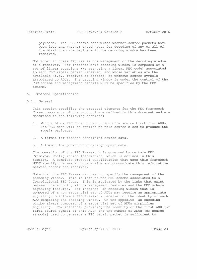
Not shown in these Figures is the management of the decoding window at a receiver. For instance this decoding window is composed of a set of linear equations (we are using a linear FEC code) associated to each FEC repair packet received, and whose variables are the available (i.e., received or decoded) or unknown source symbols associated to ADUs. The decoding window is under the control of the FEC scheme and management details MUST be specified by the FEC scheme.
5. Protocol Specification
5.1. General
This section specifies the protocol elements for the FEC Framework. Three components of the protocol are defined in this document and are described in the following sections:
1. With a Block FEC Code, construction of a source block from ADUs. The FEC code will be applied to this source block to produce the repair payloads.
2. A format for packets containing source data.
3. A format for packets containing repair data.
The operation of the FEC Framework is governed by certain FEC Framework Configuration Information, which is defined in this section. A complete protocol specification that uses this framework MUST specify the means to determine and communicate this information between sender and receiver.
Note that the FEC Framework does not specify the management of the encoding window. This is left to the FEC scheme associated to a Convolutional FEC Code. This is motivated by the links that exist between the encoding window management features and the FEC scheme signaling features. For instance, an encoding window that is composed of a non sequential set of ADUs may require an appropriate signaling to inform a FEC Framework receiver of the identity of each ADU composing the encoding window. On the opposite, an encoding window always composed of a sequential set of ADUs simplifies signaling. For instance, providing the identity of the first ADU (or first source symbol of this ADU) and the number of ADUs (or source symbols) used to generate a FEC repair packet is sufficient to
Roca & Begen Expires April 9, 2017 [Page 23]

Internet-Draft FEC Framework version 2 October 2016
identify all the ADUs (or source symbols) present in the encoding window. Appendix A gives an example of encoding window management (non normative text).
Similarly the FEC Framework does not specify the management of the decoding window which is also left to the FEC scheme associated to a Convolutional FEC Code.
Note that the FEC Framework does not specify the ADU to source symbol mapping, neither for Block FEC Codes nor for Convolutional FEC Codes.
5.2. Structure of the Source Block with Block FEC Codes
The FEC Framework and FEC scheme exchange ADUs in the form of source blocks. A source block is generated by the FEC Framework from an ordered sequence of ADUs. The allocation of ADUs to blocks is dependent on the application. Note that some ADUs may not be included in any block. Each source block provided to the FEC scheme consists of an ordered sequence of ADUs where the following information is provided for each ADU:
o A description of the source flow with which the ADU is associated.
o The ADU itself.
o The length of the ADU.
5.3. Packet Format for FEC Source Packets
The packet format for FEC source packets MUST be used to transport the payload of an original source packet. As depicted in Figure 8, it consists of the original packet, optionally followed by the Explicit Source FEC Payload ID field. The FEC scheme determines whether the Explicit Source FEC Payload ID field is required. This determination is specific to each ADU flow.
+------------------------------------+ | IP Header | +------------------------------------+ | Transport Header | +------------------------------------+ | Application Data Unit | +------------------------------------+ | Explicit Source FEC Payload ID | +------------------------------------+
Figure 8: Structure of the FEC Packet Format for FEC Source Packets
Roca & Begen Expires April 9, 2017 [Page 24]

Internet-Draft FEC Framework version 2 October 2016
The FEC source packets MUST be sent using the same ADU flow as would have been used for the original source packets if the FEC Framework were not present. The transport payload of the FEC source packet MUST consist of the ADU followed by the Explicit Source FEC Payload ID field, if required.
The Explicit Source FEC Payload ID field contains information required to associate the source packet with a source block (in case of Block FEC Code) or to the source flow (in case of Convolutional FEC code) and for the operation of the FEC algorithm, and is defined by the FEC scheme. The format of the Source FEC Payload ID field is defined by the FEC scheme. In the case that the FEC scheme or CDP defines a means to derive the Source FEC Payload ID from other information in the packet (for example, a sequence number used by the application protocol), then the Source FEC Payload ID field is not included in the packet. In this case, the original source packet and FEC source packet are identical.
In applications where avoidance of IP packet fragmentation is a goal, CDPs SHOULD consider the Explicit Source FEC Payload ID size when determining the size of ADUs that will be delivered using the FEC Framework. This is because the addition of the Explicit Source FEC Payload ID increases the packet length.
The Explicit Source FEC Payload ID is placed at the end of the packet, so that in the case that Robust Header Compression (ROHC) [RFC3095] or other header compression mechanisms are used, and in the case that a ROHC profile is defined for the protocol carried within the transport payload (for example, RTP), then ROHC will still be applied for the FEC source packets. Applications that are used with this framework need to consider that FEC schemes can add this Explicit Source FEC Payload ID and thereby increase the packet size.
In many applications, support for FEC is added to a pre-existing protocol, and in this case, use of the Explicit Source FEC Payload ID can break backward compatibility, since source packets are modified.
5.3.1. Generic Explicit Source FEC Payload ID
In order to apply FEC protection using multiple FEC schemes to a single source flow, all schemes have to use the same Explicit Source FEC Payload ID format. In order to enable this, it is RECOMMENDED that FEC schemes support the Generic Explicit Source FEC Payload ID format described below.
The Generic Explicit Source FEC Payload ID has a length of two octets and consists of an unsigned packet sequence number in network-byte order. The allocation of sequence numbers to packets is independent
Roca & Begen Expires April 9, 2017 [Page 25]

Internet-Draft FEC Framework version 2 October 2016
of any FEC scheme and of the source block construction or encoding window management, except that the use of this sequence number places a constraint on source block construction or encoding window management. Source packets within a given source block or encoding window MUST have consecutive sequence numbers (where consecutive includes wrap-around from the maximum value that can be represented in two octets (65535) to 0). Sequence numbers SHOULD NOT be reused until all values in the sequence number space have been used.
Note that if the original packets of the source flow are already carrying a packet sequence number that is at least two bytes long, there is no need to add the generic Explicit Source FEC Payload ID and modify the packets.
5.4. Packet Format for FEC Repair Packets
The packet format for FEC repair packets is shown in Figure 9. The transport payload consists of a Repair FEC Payload ID field followed by repair data generated in the FEC encoding process.
+------------------------------------+ | IP Header | +------------------------------------+ | Transport Header | +------------------------------------+ | Repair FEC Payload ID | +------------------------------------+ | Repair Symbols | +------------------------------------+
Figure 9: Packet Format for FEC Repair Packets
The Repair FEC Payload ID field contains information required for the operation of the FEC algorithm at the receiver. This information is defined by the FEC scheme. The format of the Repair FEC Payload ID field is defined by the FEC scheme.
5.4.1. Packet Format for FEC Repair Packets over RTP
For FEC schemes that specify the use of RTP for repair packets, the packet format for repair packets includes an RTP header as shown in Figure 10.
Roca & Begen Expires April 9, 2017 [Page 26]

Internet-Draft FEC Framework version 2 October 2016
+------------------------------------+ | IP Header | +------------------------------------+ | Transport Header (UDP) | +------------------------------------+ | RTP Header | +------------------------------------+ | Repair FEC Payload ID | +------------------------------------+ | Repair Symbols | +------------------------------------+
Figure 10: Packet Format for FEC Repair Packets over RTP
5.5. FEC Framework Configuration Information
The FEC Framework Configuration Information is information that the FEC Framework needs in order to apply FEC protection to the ADU flows. A complete CDP specification that uses the framework specified here MUST include details of how this information is derived and communicated between sender and receiver.
The FEC Framework Configuration Information includes identification of the set of source flows. For example, in the case of UDP, each source flow is uniquely identified by a tuple {source IP address, source UDP port, destination IP address, destination UDP port}. In some applications, some of these fields can contain wildcards, so that the flow is identified by a subset of the fields. In particular, in many applications the limited tuple {destination IP address, destination UDP port} is sufficient.
A single instance of the FEC Framework provides FEC protection for packets of the specified set of source flows, by means of one or more packet flows consisting of repair packets. The FEC Framework Configuration Information includes, for each instance of the FEC Framework:
1. Identification of the repair flows.
2. For each source flow protected by the repair flow(s):
A. Definition of the source flow.
B. An integer identifier for this flow definition (i.e., tuple). This identifier MUST be unique among all source flows that are protected by the same FEC repair flow. Integer identifiers can be allocated starting from zero and increasing by one for each flow. However, any random (but
Roca & Begen Expires April 9, 2017 [Page 27]

Internet-Draft FEC Framework version 2 October 2016
still unique) allocation is also possible. A source flow identifier need not be carried in source packets, since source packets are directly associated with a flow by virtue of their packet headers.
3. The FEC Encoding ID, identifying the FEC scheme.
4. The length of the Explicit Source FEC Payload ID (in octets).
5. Zero or more FEC-Scheme-Specific Information (FSSI) elements, each consisting of a name and a value where the valid element names and value ranges are defined by the FEC scheme.
Multiple instances of the FEC Framework, with separate and independent FEC Framework Configuration Information, can be present at a sender or receiver. A single instance of the FEC Framework protects packets of the source flows identified in (2) above; i.e., all packets sent on those flows MUST be FEC source packets as defined in Section 5.3. A single source flow can be protected by multiple instances of the FEC Framework.
The integer flow identifier identified in (2B) above is a shorthand to identify source flows between the FEC Framework and the FEC scheme. The reason for defining this as an integer, and including it in the FEC Framework Configuration Information, is so that the FEC scheme at the sender and receiver can use it to identify the source flow with which a recovered packet is associated. The integer flow identifier can therefore take the place of the complete flow description (e.g., UDP 4-tuple).
Whether and how this flow identifier is used is defined by the FEC scheme. Since repair packets can provide protection for multiple source flows, repair packets either would not carry the identifier at all or can carry multiple identifiers. However, in any case, the flow identifier associated with a particular source packet can be recovered from the repair packets as part of a FEC decoding operation.
A single FEC repair flow provides repair packets for a single instance of the FEC Framework. Other packets MUST NOT be sent within this flow; i.e., all packets in the FEC repair flow MUST be FEC repair packets as defined in Section 5.4 and MUST relate to the same FEC Framework instance.
In the case that RTP is used for repair packets, the identification of the repair packet flow can also include the RTP payload type to be used for repair packets.
Roca & Begen Expires April 9, 2017 [Page 28]

Internet-Draft FEC Framework version 2 October 2016
FSSI includes the information that is specific to the FEC scheme used by the CDP. FSSI is used to communicate the information that cannot be adequately represented otherwise and is essential for proper FEC encoding and decoding operations. The motivation behind separating the FSSI required only by the sender (which is carried in a Sender- Side FEC-Scheme-Specific Information (SS-FSSI) container) from the rest of the FSSI is to provide the receiver or the third-party entities a means of controlling the FEC operations at the sender. Any FSSI other than the one solely required by the sender MUST be communicated via the FSSI container.
The variable-length SS-FSSI and FSSI containers transmit the information in textual representation and contain zero or more distinct elements, whose descriptions are provided by the fully specified FEC schemes.
For the CDPs that choose the Session Description Protocol (SDP) [RFC4566] for their multimedia sessions, the ABNF [RFC5234] syntax for the SS-FSSI and FSSI containers is provided in Section 4.5 of [RFC6364].
5.6. FEC Scheme Requirements
In order to be used with this framework, a FEC scheme MUST be capable of processing data either arranged into blocks of ADUs (source blocks) in case of a Block FEC Code, or arranged as a continuous flow of ADUs in case of a Convolutional FEC Code.
A specification for a new FEC scheme MUST include the following:
1. The FEC Encoding ID value that uniquely identifies the FEC scheme. This value MUST be registered with IANA, as described in Section 12.
2. The type, semantics, and encoding format of the Repair FEC Payload ID.
3. The name, type, semantics, and text value encoding rules for zero or more FEC-Scheme-Specific Information elements.
4. A full specification of the FEC code.
This specification MUST precisely define the valid FEC-Scheme- Specific Information values, the valid FEC Payload ID values, and the valid packet payload sizes (where packet payload refers to the space within a packet dedicated to carrying encoding symbols).
Roca & Begen Expires April 9, 2017 [Page 29]

Internet-Draft FEC Framework version 2 October 2016
Furthermore, given valid values of the FEC-Scheme-Specific Information, a valid Repair FEC Payload ID value, a valid packet payload size and in case of a Block FEC Code a source block as defined in Section 5.2, the specification MUST uniquely define the values of the encoding symbols to be included in the repair packet payload of a packet with the given Repair FEC Payload ID value.
A common and simple way to specify the FEC code to the required level of detail is to provide a precise specification of an encoding algorithm that -- given valid values of the FEC-Scheme- Specific Information, a valid Repair FEC Payload ID value, a valid packet payload size, and in case of a Block FEC Code a source block as input -- produces the exact value of the encoding symbols as output.
5. A description of practical encoding and decoding algorithms.
This description need not be to the same level of detail as for the encoding above; however, it has to be sufficient to demonstrate that encoding and decoding of the code are both possible and practical.
FEC scheme specifications MAY additionally define the following:
Type, semantics, and encoding format of an Explicit Source FEC Payload ID.
Whenever a FEC scheme specification defines an ’encoding format’ for an element, this has to be defined in terms of a sequence of bytes that can be embedded within a protocol. The length of the encoding format either MUST be fixed or it MUST be possible to derive the length from examining the encoded bytes themselves. For example, the initial bytes can include some kind of length indication.
FEC scheme specifications SHOULD use the terminology defined in this document and SHOULD follow the following format:
1. Introduction <Describe the use cases addressed by this FEC scheme>
2. Formats and Codes
2.1. Source FEC Payload ID(s) <Either define the type and format of the Explicit Source FEC Payload ID or define how Source FEC Payload ID information is derived from source packets>
Roca & Begen Expires April 9, 2017 [Page 30]

Internet-Draft FEC Framework version 2 October 2016
2.2. Repair FEC Payload ID <Define the type and format of the Repair FEC Payload ID>
2.3. FEC Framework Configuration Information <Define the names, types, and text value encoding formats of the FEC-Scheme- Specific Information elements>
3. Procedures <Describe any procedures that are specific to this FEC scheme, in particular derivation and interpretation of the fields in the FEC Payload IDs and FEC-Scheme-Specific Information>
4. FEC Code Specification <Provide a complete specification of the FEC Code>
Specifications can include additional sections including examples.
Each FEC scheme MUST be specified independently of all other FEC schemes, for example, in a separate specification or a completely independent section of a larger specification (except, of course, a specification of one FEC scheme can include portions of another by reference). Where an RTP payload format is defined for repair data for a specific FEC scheme, the RTP payload format and the FEC scheme can be specified within the same document.
6. Feedback
Many applications require some kind of feedback on transport performance, e.g., how much data arrived at the receiver, at what rate, and when? When FEC is added to such applications, feedback mechanisms may also need to be enhanced to report on the performance of the FEC, e.g., how much lost data was recovered by the FEC?
When used to provide instrumentation for engineering purposes, it is important to remember that FEC is generally applied to relatively small sets of data (in the sense that each block or symbols of an encoding window is transmitted over a relatively small period of time). Thus, feedback information that is averaged over longer periods of time will likely not provide sufficient information for engineering purposes. More detailed feedback over shorter time scales might be preferred. For example, for applications using RTP transport, see [RFC5725].
Applications that use feedback for congestion control purposes MUST calculate such feedback on the basis of packets received before FEC recovery is applied. If this requirement conflicts with other uses of the feedback information, then the application MUST be enhanced to support information calculated both pre- and post-FEC recovery. This
Roca & Begen Expires April 9, 2017 [Page 31]
Internet-Draft FEC Framework version 2 October 2016
is to ensure that congestion control mechanisms operate correctly based on congestion indications received from the network, rather than on post-FEC recovery information that would give an inaccurate picture of congestion conditions.
New applications that require such feedback SHOULD use RTP/RTCP [RFC3550].
7. Transport Protocols
This framework is intended to be used to define CDPs that operate over transport protocols providing an unreliable datagram service, including in particular the User Datagram Protocol (UDP) and the Datagram Congestion Control Protocol (DCCP).
8. Congestion Control
This section starts with some informative background on the motivation of the normative requirements for congestion control, which are spelled out in Section 8.2.
8.1. Motivation
o The enforcement of congestion control principles has gained a lot of momentum in the IETF over recent years. While the need for congestion control over the open Internet is unquestioned, and the goal of TCP friendliness is generally agreed upon for most (but not all) applications, the problem of congestion detection and measurement in heterogeneous networks can hardly be considered solved. Most congestion control algorithms detect and measure congestion by taking (primarily or exclusively) the packet loss rate into account. This appears to be inappropriate in environments where a large percentage of the packet losses are the result of link-layer errors and independent of the network load.
o The authors of this document are primarily interested in applications where the application reliability requirements and end-to-end reliability of the network differ, such that it warrants higher-layer protection of the packet stream, e.g., due to the presence of unreliable links in the end-to-end path and where real-time, scalability, or other constraints prohibit the use of higher-layer (transport or application) feedback. A typical example for such applications is multicast and broadcast streaming or multimedia transmission over heterogeneous networks. In other cases, application reliability requirements can be so high that the required end-to-end reliability will be difficult to achieve. Furthermore, the end-to-end network reliability is not necessarily known in advance.
Roca & Begen Expires April 9, 2017 [Page 32]

Internet-Draft FEC Framework version 2 October 2016
o This FEC Framework is not defined as, nor is it intended to be, a quality-of-service (QoS) enhancement tool to combat losses resulting from highly congested networks. It should not be used for such purposes.
o In order to prevent such misuse, one approach is to leave standardization to bodies most concerned with the problem described above. However, the IETF defines base standards used by several bodies, including the Digital Video Broadcasting (DVB) Project, the Third Generation Partnership Project (3GPP), and 3GPP2, all of which appear to share the environment and the problem described.
o Another approach is to write a clear applicability statement. For example, one could restrict the use of this framework to networks with certain loss characteristics (e.g., wireless links). However, there can be applications where the use of FEC is justified to combat congestion-induced packet losses -- particularly in lightly loaded networks, where congestion is the result of relatively rare random peaks in instantaneous traffic load -- thereby intentionally violating congestion control principles. One possible example for such an application could be a no-matter-what, brute-force FEC protection of traffic generated as an emergency signal.
o A third approach is to require, at a minimum, that the use of this framework with any given application, in any given environment, does not cause congestion issues that the application alone would not itself cause; i.e., the use of this framework must not make things worse.
o Taking the above considerations into account, Section 8.2 specifies a small set of constraints for FEC; these constraints are mandatory for all senders compliant with this FEC Framework. Further restrictions can be imposed by certain CDPs.
8.2. Normative Requirements
o The bandwidth of FEC repair data MUST NOT exceed the bandwidth of the original source data being protected (without the possible addition of an Explicit Source FEC Payload ID). This disallows the (static or dynamic) use of excessively strong FEC to combat high packet loss rates, which can otherwise be chosen by naively implemented dynamic FEC-strength selection mechanisms. We acknowledge that there are a few exotic applications, e.g., IP traffic from space-based senders, or senders in certain hardened military devices, that could warrant a higher FEC strength.
Roca & Begen Expires April 9, 2017 [Page 33]

Internet-Draft FEC Framework version 2 October 2016
However, in this specification, we give preference to the overall stability and network friendliness of average applications.
o Whenever the source data rate is adapted due to the operation of congestion control mechanisms, the FEC repair data rate MUST be similarly adapted.
9. Implementation Status
Editor’s notes:
o RFC Editor, please remove this section motivated by RFC 7942 before publishing the RFC. Thanks.
An implementation of FECFRAME version 2 exists:
o Organisation: Inria
o Description: This is an implementation of FECFRAME version 2, using the (convolutional) RLC FEC Scheme (see "RLC FEC Scheme I-D" when available). It is based on:
* an implementation of FECFRAME, made by Inria and commercialized by Expway (http://www.expway.com/), for which interoperability tests have been conducted;
* a proprietary implementation of RLC Convolutional FEC Codes.
o Maturity: the FECFRAME version 1 maturity is "production", the FECFRAME version 2 extension maturity is "under progress".
o Coverage: the software implements a subset of [RFC6363], as specialized by the 3GPP eMBMS standard [MBMSTS]. This software also covers the additional features of FECFRAME version 2 for convolutional codes, relying on the RLC FEC Scheme.
o Lincensing: proprietary.
o Implementation experience: maximum.
o Information update date: October 2016.
o Contact: [email protected]
Roca & Begen Expires April 9, 2017 [Page 34]

Internet-Draft FEC Framework version 2 October 2016
10. Security Considerations
First of all, it must be clear that the application of FEC protection to a stream does not provide any kind of security. On the contrary, the FEC Framework itself could be subject to attacks or could pose new security risks. The goals of this section are to state the problem, discuss the risks, and identify solutions when feasible. It also defines a mandatory-to-implement (but not mandatory-to-use) security scheme.
10.1. Problem Statement
A content delivery system is potentially subject to many attacks. Attacks can target the content, the CDP, or the network itself, with completely different consequences, particularly in terms of the number of impacted nodes.
Attacks can have several goals:
o They can try to give access to confidential content (e.g., in the case of non-free content).
o They can try to corrupt the source flows (e.g., to prevent a receiver from using them), which is a form of denial-of-service (DoS) attack.
o They can try to compromise the receiver’s behavior (e.g., by making the decoding of an object computationally expensive), which is another form of DoS attack.
o They can try to compromise the network’s behavior (e.g., by causing congestion within the network), which potentially impacts a large number of nodes.
These attacks can be launched either against the source and/or repair flows (e.g., by sending fake FEC source and/or repair packets) or against the FEC parameters that are sent either in-band (e.g., in the Repair FEC Payload ID or in the Explicit Source FEC Payload ID) or out-of-band (e.g., in the FEC Framework Configuration Information).
Several dimensions to the problem need to be considered. The first one is the way the FEC Framework is used. The FEC Framework can be used end-to-end, i.e., it can be included in the final end-device where the upper application runs, or the FEC Framework can be used in middleboxes, for instance, to globally protect several source flows exchanged between two or more distant sites.
Roca & Begen Expires April 9, 2017 [Page 35]

Internet-Draft FEC Framework version 2 October 2016
A second dimension is the threat model. When the FEC Framework operates in the end-device, this device (e.g., a personal computer) might be subject to attacks. Here, the attacker is either the end- user (who might want to access confidential content) or somebody else. In all cases, the attacker has access to the end-device but does not necessarily fully control this end-device (a secure domain can exist). Similarly, when the FEC Framework operates in a middlebox, this middlebox can be subject to attacks or the attacker can gain access to it. The threats can also concern the end-to-end transport (e.g., through the Internet). Here, examples of threats include the transmission of fake FEC source or repair packets; the replay of valid packets; the drop, delay, or misordering of packets; and, of course, traffic eavesdropping.
The third dimension consists in the desired security services. Among them, the content integrity and sender authentication services are probably the most important features. We can also mention DoS mitigation, anti-replay protection, or content confidentiality.
Finally, the fourth dimension consists in the security tools available. This is the case of the various Digital Rights Management (DRM) systems, defined outside of the context of the IETF, that can be proprietary solutions. Otherwise, the Secure Real-Time Transport Protocol (SRTP) [RFC3711] and IPsec/Encapsulating Security Payload (IPsec/ESP) [RFC4303] are two tools that can turn out to be useful in the context of the FEC Framework. Note that using SRTP requires that the application generate RTP source flows and, when applied below the FEC Framework, that both the FEC source and repair packets be regular RTP packets. Therefore, SRTP is not considered to be a universal solution applicable in all use cases.
In the following sections, we further discuss security aspects related to the use of the FEC Framework.
10.2. Attacks against the Data Flows
10.2.1. Access to Confidential Content
Access control to the source flow being transmitted is typically provided by means of encryption. This encryption can be done by the content provider itself, or within the application (for instance, by using SRTP [RFC3711]), or at the network layer on a per-packet basis when IPsec/ESP is used [RFC4303]. If confidentiality is a concern, it is RECOMMENDED that one of these solutions be used. Even if we mention these attacks here, they are neither related to nor facilitated by the use of FEC.
Roca & Begen Expires April 9, 2017 [Page 36]

Internet-Draft FEC Framework version 2 October 2016
Note that when encryption is applied, this encryption MUST be applied either on the source data before the FEC protection or, if done after the FEC protection, on both the FEC source packets and repair packets (and an encryption at least as cryptographically secure as the encryption applied on the FEC source packets MUST be used for the FEC repair packets). Otherwise, if encryption were to be performed only on the FEC source packets after FEC encoding, a non-authorized receiver could be able to recover the source data after decoding the FEC repair packets, provided that a sufficient number of such packets were available.
The following considerations apply when choosing where to apply encryption (and more generally where to apply security services beyond encryption). Once decryption has taken place, the source data is in plaintext. The full path between the output of the deciphering module and the final destination (e.g., the TV display in the case of a video) MUST be secured, in order to prevent any unauthorized access to the source data.
When the FEC Framework endpoint is the end-system (i.e., where the upper application runs) and if the threat model includes the possibility that an attacker has access to this end-system, then the end-system architecture is very important. More precisely, in order to prevent an attacker from getting hold of the plaintext, all processing, once deciphering has taken place, MUST occur in a protected environment. If encryption is applied after FEC protection at the sending side (i.e., below the FEC Framework), it means that FEC decoding MUST take place in the protected environment. With certain use cases, this MAY be complicated or even impossible. In such cases, applying encryption before FEC protection is preferred.
When the FEC Framework endpoint is a middlebox, the recovered source flow, after FEC decoding, SHOULD NOT be sent in plaintext to the final destination(s) if the threat model includes the possibility that an attacker eavesdrops on the traffic. In that case, it is preferable to apply encryption before FEC protection.
In some cases, encryption could be applied both before and after the FEC protection. The considerations described above still apply in such cases.
10.2.2. Content Corruption
Protection against corruptions (e.g., against forged FEC source/ repair packets) is achieved by means of a content integrity verification/source authentication scheme. This service is usually provided at the packet level. In this case, after removing all the forged packets, the source flow might sometimes be recovered.
Roca & Begen Expires April 9, 2017 [Page 37]

Internet-Draft FEC Framework version 2 October 2016
Several techniques can provide this content integrity/source authentication service:
o At the application layer, SRTP [RFC3711] provides several solutions to check the integrity and authenticate the source of RTP and RTCP messages, among other services. For instance, when associated with the Timed Efficient Stream Loss-Tolerant Authentication (TESLA) [RFC4383], SRTP is an attractive solution that is robust to losses, provides a true authentication/integrity service, and does not create any prohibitive processing load or transmission overhead. Yet, with TESLA, checking a packet requires a small delay (a second or more) after its reception. Whether or not this extra delay, both in terms of startup delay at the client and end-to-end delay, is appropriate depends on the target use case. In some situations, this might degrade the user experience. In other situations, this will not be an issue. Other building blocks can be used within SRTP to provide content integrity/authentication services.
o At the network layer, IPsec/ESP [RFC4303] offers (among other services) an integrity verification mechanism that can be used to provide authentication/content integrity services.
It is up to the developer and the person in charge of deployment, who know the security requirements and features of the target application area, to define which solution is the most appropriate. Nonetheless, it is RECOMMENDED that at least one of these techniques be used.
Note that when integrity protection is applied, it is RECOMMENDED that it take place on both FEC source and repair packets. The motivation is to keep corrupted packets from being considered during decoding, as such packets would often lead to a decoding failure or result in a corrupted decoded source flow.
10.3. Attacks against the FEC Parameters
Attacks on these FEC parameters can prevent the decoding of the associated object. For instance, modifying the finite field size of a Reed-Solomon FEC scheme (when applicable) will lead a receiver to consider a different FEC code.
Therefore, it is RECOMMENDED that security measures be taken to guarantee the integrity of the FEC Framework Configuration Information. Since the FEC Framework does not define how the FEC Framework Configuration Information is communicated from sender to receiver, we cannot provide further recommendations on how to guarantee its integrity. However, any complete CDP specification MUST give recommendations on how to achieve it. When the FEC
Roca & Begen Expires April 9, 2017 [Page 38]

Internet-Draft FEC Framework version 2 October 2016
Framework Configuration Information is sent out-of-band, e.g., in a session description, it SHOULD be protected, for instance, by digitally signing it.
Attacks are also possible against some FEC parameters included in the Explicit Source FEC Payload ID and Repair FEC Payload ID. For instance, with a Block FEC Code, modifying the Source Block Number of a FEC source or repair packet will lead a receiver to assign this packet to a wrong block.
Therefore, it is RECOMMENDED that security measures be taken to guarantee the integrity of the Explicit Source FEC Payload ID and Repair FEC Payload ID. To that purpose, one of the packet-level source authentication/content integrity techniques described in Section 10.2.2 can be used.
10.4. When Several Source Flows Are to Be Protected Together
When several source flows, with different security requirements, need to be FEC protected jointly, within a single FEC Framework instance, then each flow MAY be processed appropriately, before the protection. For instance, source flows that require access control MAY be encrypted before they are FEC protected.
There are also situations where the only insecure domain is the one over which the FEC Framework operates. In that case, this situation MAY be addressed at the network layer, using IPsec/ESP (see Section 10.5), even if only a subset of the source flows has strict security requirements.
Since the use of the FEC Framework should not add any additional threat, it is RECOMMENDED that the FEC Framework aggregate flow be in line with the maximum security requirements of the individual source flows. For instance, if denial-of-service (DoS) protection is required, an integrity protection SHOULD be provided below the FEC Framework, using, for instance, IPsec/ESP.
Generally speaking, whenever feasible, it is RECOMMENDED that FEC protecting flows with totally different security requirements be avoided. Otherwise, significant processing overhead would be added to protect source flows that do not need it.
10.5. Baseline Secure FEC Framework Operation
The FEC Framework has been defined in such a way to be independent from the application that generates source flows. Some applications might use purely unidirectional flows, while other applications might
Roca & Begen Expires April 9, 2017 [Page 39]

Internet-Draft FEC Framework version 2 October 2016
also use unicast feedback from the receivers. For instance, this is the case when considering RTP/RTCP-based source flows.
This section describes a baseline mode of secure FEC Framework operation based on the application of the IPsec protocol, which is one possible solution to solve or mitigate the security threats introduced by the use of the FEC Framework.
Two related documents are of interest. First, Section 5.1 of [RFC5775] defines a baseline secure Asynchronous Layered Coding (ALC) operation for sender-to-group transmissions, assuming the presence of a single sender and a source-specific multicast (SSM) or SSM-like operation. The proposed solution, based on IPsec/ESP, can be used to provide a baseline FEC Framework secure operation, for the downstream source flow.
Second, Section 7.1 of [RFC5740] defines a baseline secure NACK- Oriented Reliable Multicast (NORM) operation, for sender-to-group transmissions as well as unicast feedback from receivers. Here, it is also assumed there is a single sender. The proposed solution is also based on IPsec/ESP. However, the difference with respect to [RFC5775] relies on the management of IPsec Security Associations (SAs) and corresponding Security Policy Database (SPD) entries, since NORM requires a second set of SAs and SPD entries to be defined to protect unicast feedback from receivers.
Note that the IPsec/ESP requirement profiles outlined in [RFC5775] and [RFC5740] are commonly available on many potential hosts. They can form the basis of a secure mode of operation. Configuration and operation of IPsec typically require privileged user authorization. Automated key management implementations are typically configured with the privileges necessary to allow the needed system IPsec configuration.
11. Operations and Management Considerations
The question of operating and managing the FEC Framework and the associated FEC scheme(s) is of high practical importance. The goals of this section are to discuss aspects and recommendations related to specific deployments and solutions.
In particular, this section discusses the questions of interoperability across vendors/use cases and whether defining mandatory-to-implement (but not mandatory-to-use) solutions is beneficial.
Roca & Begen Expires April 9, 2017 [Page 40]

Internet-Draft FEC Framework version 2 October 2016
11.1. What Are the Key Aspects to Consider?
Several aspects need to be considered, since they will directly impact the way the FEC Framework and the associated FEC schemes can be operated and managed.
This section lists them as follows:
1. A Single Small Generic Component within a Larger (and Often Legacy) Solution: The FEC Framework is one component within a larger solution that includes one or several upper-layer applications (that generate one or several ADU flows) and an underlying protocol stack. A key design principle is that the FEC Framework should be able to work without making any assumption with respect to either the upper-layer application(s) or the underlying protocol stack, even if there are special cases where assumptions are made.
2. One-to-One with Feedback vs. One-to-Many with Feedback vs. One- to-Many without Feedback Scenarios: The FEC Framework can be used in use cases that completely differ from one another. Some use cases are one-way (e.g., in broadcast networks), with either a one-to-one, one-to-many, or many-to-many transmission model, and the receiver(s) cannot send any feedback to the sender(s). Other use cases follow a bidirectional one-to-one, one-to-many, or many-to-many scenario, and the receiver(s) can send feedback to the sender(s).
3. Non-FEC Framework Capable Receivers: With the one-to-many and many-to-many use cases, the receiver population might have different capabilities with respect to the FEC Framework itself and the supported FEC schemes. Some receivers might not be capable of decoding the repair packets belonging to a particular FEC scheme, while some other receivers might not support the FEC Framework at all.
4. Internet vs. Non-Internet Networks: The FEC Framework can be useful in many use cases that use a transport network that is not the public Internet (e.g., with IPTV or Mobile TV). In such networks, the operational and management considerations can be achieved through an open or proprietary solution, which is specified outside of the IETF.
5. Congestion Control Considerations: See Section 8 for a discussion on whether or not congestion control is needed, and its relationships with the FEC Framework.
Roca & Begen Expires April 9, 2017 [Page 41]

Internet-Draft FEC Framework version 2 October 2016
6. Within End-Systems vs. within Middleboxes: The FEC Framework can be used within end-systems, very close to the upper-layer application, or within dedicated middleboxes (for instance, when it is desired to protect one or several flows while they cross a lossy channel between two or more remote sites).
7. Protecting a Single Flow vs. Several Flows Globally: The FEC Framework can be used to protect a single flow or several flows globally.
11.2. Operational and Management Recommendations
Overall, from the discussion in Section 11.1, it is clear that the CDPs and FEC schemes compatible with the FEC Framework differ widely in their capabilities, application, and deployment scenarios such that a common operation and management method or protocol that works well for all of them would be too complex to define. Thus, as a design choice, the FEC Framework does not dictate the use of any particular technology or protocol for transporting FEC data, managing the hosts, signaling the configuration information, or encoding the configuration information. This provides flexibility and is one of the main goals of the FEC Framework. However, this section gives some RECOMMENDED guidelines.
1. A Single Small Generic Component within a Larger (and Often Legacy) Solution: It is anticipated that the FEC Framework will often be used to protect one or several RTP streams. Therefore, implementations SHOULD make feedback information accessible via RTCP to enable users to take advantage of the tools using (or used by) RTCP to operate and manage the FEC Framework instance along with the associated FEC schemes.
2. One-to-One with Feedback vs. One-to-Many with Feedback vs. One- to-Many without Feedback Scenarios: With use cases that are one- way, the FEC Framework sender does not have any way to gather feedback from receivers. With use cases that are bidirectional, the FEC Framework sender can collect detailed feedback (e.g., in the case of a one-to-one scenario) or at least occasional feedback (e.g., in the case of a multicast, one-to-many scenario). All these applications have naturally different operational and management aspects. They also have different requirements or features, if any, for collecting feedback, processing it, and acting on it. The data structures for carrying the feedback also vary.
Implementers SHOULD make feedback available using either an in- band or out-of-band asynchronous reporting mechanism. When an out-of-band solution is preferred, a standardized reporting
Roca & Begen Expires April 9, 2017 [Page 42]

Internet-Draft FEC Framework version 2 October 2016
mechanism, such as Syslog [RFC5424] or Simple Network Management Protocol (SNMP) notifications [RFC3411], is RECOMMENDED. When required, a mapping mechanism between the Syslog and SNMP reporting mechanisms could be used, as described in [RFC5675] and [RFC5676].
3. Non-FEC Framework Capable Receivers: Section 5.3 gives recommendations on how to provide backward compatibility in the presence of receivers that cannot support the FEC scheme being used or the FEC Framework itself: basically, the use of Explicit Source FEC Payload ID is banned. Additionally, a non-FEC Framework capable receiver MUST also have a means not to receive the repair packets that it will not be able to decode in the first place or a means to identify and discard them appropriately upon receiving them. This SHOULD be achieved by sending repair packets on a different transport-layer flow. In the case of RTP transport, and if both source and repair packets will be sent on the same transport-layer flow, this SHOULD be achieved by using an RTP framing for FEC repair packets with a different payload type. It is the responsibility of the sender to select the appropriate mechanism when needed.
4. Within End-Systems vs. within Middleboxes: When the FEC Framework is used within middleboxes, it is RECOMMENDED that the paths between the hosts where the sending applications run and the middlebox that performs FEC encoding be as reliable as possible, i.e., not be prone to packet loss, packet reordering, or varying delays in delivering packets.
Similarly, when the FEC Framework is used within middleboxes, it is RECOMMENDED that the paths be as reliable as possible between the middleboxes that perform FEC decoding and the end-systems where the receiving applications operate.
5. Management of Communication Issues before Reaching the Sending FECFRAME Instance: Let us consider situations where the FEC Framework is used within middleboxes. At the sending side, the general reliability recommendation for the path between the sending applications and the middlebox is important, but it may not guarantee that a loss, reordering, or long delivery delay cannot happen, for whatever reason. If such a rare event happens, this event SHOULD NOT compromise the operation of the FECFRAME instances, at either the sending side or the receiving side. This is particularly important with FEC schemes that do not modify the ADU for backward-compatibility purposes (i.e., do not use any Explicit Source FEC Payload ID) and rely on, for instance, the RTP sequence number field to identify FEC source
Roca & Begen Expires April 9, 2017 [Page 43]
Internet-Draft FEC Framework version 2 October 2016
packets within their source block (Block FEC Code) or source flow (Convolutional FEC Code). In this case, packet loss or packet reordering leads to a gap in the RTP sequence number space seen by the FECFRAME instance. Similarly, varying delay in delivering packets over this path can lead to significant timing issues. With FEC schemes for a Block FEC Code that indicate in the Repair FEC Payload ID, for each source block, the base RTP sequence number and number of consecutive RTP packets that belong to this source block, a missing ADU or an ADU delivered out of order could cause the FECFRAME sender to switch to a new source block. However, some FEC schemes and/or receivers may not necessarily handle such varying source block sizes. In this case, one could consider duplicating the last ADU received before the loss, or inserting zeroed ADU(s), depending on the nature of the ADU flow. Implementers SHOULD consider the consequences of such alternative approaches, based on their use cases.
6. Protecting a Single Flow vs. Several Flows Globally: In the general case, the various ADU flows that are globally protected can have different features, and in particular different real- time requirements (in the case of real-time flows). The process of globally protecting these flows SHOULD take into account the requirements of each individual flow. In particular, it would be counterproductive to add repair traffic to a real-time flow for which the FEC decoding delay at a receiver makes decoded ADUs for this flow useless because they do not satisfy the associated real-time constraints. From a practical point of view, this means that the source block creation process (Block FEC Code) or encoding window management process (Convolutional FEC Code) at the sending FEC Framework instance SHOULD consider the most stringent real-time requirements of the ADU flows being globally protected.
7. ADU Flow Bundle Definition and Flow Delivery: By design, a repair flow might enable a receiver to recover the ADU flow(s) that it protects even if none of the associated FEC source packets are received. Therefore, when defining the bundle of ADU flows that are globally protected and when defining which receiver receives which flow, the sender SHOULD make sure that the ADU flow(s) and repair flow(s) of that bundle will only be received by receivers that are authorized to receive all the ADU flows of that bundle. See Section 10.4 for additional recommendations for situations where strict access control for ADU flows is needed.
Additionally, when multiple ADU flows are globally protected, a receiver that wants to benefit from FECFRAME loss protection SHOULD receive all the ADU flows of the bundle. Otherwise, the
Roca & Begen Expires April 9, 2017 [Page 44]
Internet-Draft FEC Framework version 2 October 2016
missing FEC source packets would be considered lost, which might significantly reduce the efficiency of the FEC scheme.
12. IANA Considerations
FEC schemes for use with this framework are identified in protocols using FEC Encoding IDs. Values of FEC Encoding IDs are subject to IANA registration. For this purpose, this document reuses the registry called the "FEC Framework (FECFRAME) FEC Encoding IDs".
The values that can be assigned within the "FEC Framework (FECFRAME) FEC Encoding IDs" registry are numeric indexes in the range (0, 255). Values of 0 and 255 are reserved. Assignment requests are granted on an IETF Review basis as defined in [RFC5226]. Section 5.6 defines explicit requirements that documents defining new FEC Encoding IDs should meet.
13. Acknowledgments
This document is based on [RFC6363] that was initiated and mostly written by Mark Watson. Great thanks are due to you, Mark.
This document is based in part on [FEC-SF], and so thanks are due to the additional authors of that document: Mike Luby, Magnus Westerlund, and Stephan Wenger. That document was in turn based on the FEC Streaming Protocol defined by 3GPP in [MBMSTS], and thus, thanks are also due to the participants in 3GPP SA Working Group 4. Further thanks are due to the members of the FECFRAME Working Group for their comments and reviews.
14. References
14.1. Normative References
[RFC2119] Bradner, S., "Key words for use in RFCs to Indicate Requirement Levels", BCP 14, RFC 2119, DOI 10.17487/RFC2119, March 1997, <http://www.rfc-editor.org/info/rfc2119>.
[RFC3411] Harrington, D., Presuhn, R., and B. Wijnen, "An Architecture for Describing Simple Network Management Protocol (SNMP) Management Frameworks", STD 62, RFC 3411, DOI 10.17487/RFC3411, December 2002, <http://www.rfc-editor.org/info/rfc3411>.
Roca & Begen Expires April 9, 2017 [Page 45]

Internet-Draft FEC Framework version 2 October 2016
[RFC5052] Watson, M., Luby, M., and L. Vicisano, "Forward Error Correction (FEC) Building Block", RFC 5052, DOI 10.17487/RFC5052, August 2007, <http://www.rfc-editor.org/info/rfc5052>.
[RFC5226] Narten, T. and H. Alvestrand, "Guidelines for Writing an IANA Considerations Section in RFCs", BCP 26, RFC 5226, DOI 10.17487/RFC5226, May 2008, <http://www.rfc-editor.org/info/rfc5226>.
[RFC5234] Crocker, D., Ed. and P. Overell, "Augmented BNF for Syntax Specifications: ABNF", STD 68, RFC 5234, January 2008.
[RFC5424] Gerhards, R., "The Syslog Protocol", RFC 5424, DOI 10.17487/RFC5424, March 2009, <http://www.rfc-editor.org/info/rfc5424>.
[RFC6363] Watson, M., Begen, A., and V. Roca, "Forward Error Correction (FEC) Framework", RFC 6363, DOI 10.17487/RFC6363, October 2011, <http://www.rfc-editor.org/info/rfc6363>.
14.2. Informative References
[FEC-SF] Watson, M., Luby, M., Westerlund, M., and S. Wenger, "Forward Error Correction (FEC) Streaming Framework", Work in Progress, July 2005.
[FECFRAMEv2-Motivations] IRTF NetWork Coding Research Group (NWCRG), "FECFRAMEv2: Adding Sliding Encoding Window Capabilities to the FEC Framework: Problem Position", May 2016, <https://tools.ietf.org/html/draft-roca-nwcrg-fecframev2- problem-position-02>.
[MBMSTS] 3GPP, "Multimedia Broadcast/Multicast Service (MBMS); Protocols and codecs", 3GPP TS 26.346, March 2009, <http://ftp.3gpp.org/specs/html-info/26346.htm>.
[RFC3095] Bormann, C., Burmeister, C., Degermark, M., Fukushima, H., Hannu, H., Jonsson, L-E., Hakenberg, R., Koren, T., Le, K., Liu, Z., Martensson, A., Miyazaki, A., Svanbro, K., Wiebke, T., Yoshimura, T., and H. Zheng, "RObust Header Compression (ROHC): Framework and four profiles: RTP, UDP, ESP, and uncompressed", RFC 3095, DOI 10.17487/RFC3095, July 2001, <http://www.rfc-editor.org/info/rfc3095>.
Roca & Begen Expires April 9, 2017 [Page 46]

Internet-Draft FEC Framework version 2 October 2016
[RFC3550] Schulzrinne, H., Casner, S., Frederick, R., and V. Jacobson, "RTP: A Transport Protocol for Real-Time Applications", STD 64, RFC 3550, DOI 10.17487/RFC3550, July 2003, <http://www.rfc-editor.org/info/rfc3550>.
[RFC3711] Baugher, M., McGrew, D., Naslund, M., Carrara, E., and K. Norrman, "The Secure Real-time Transport Protocol (SRTP)", RFC 3711, DOI 10.17487/RFC3711, March 2004, <http://www.rfc-editor.org/info/rfc3711>.
[RFC4303] Kent, S., "IP Encapsulating Security Payload (ESP)", RFC 4303, DOI 10.17487/RFC4303, December 2005, <http://www.rfc-editor.org/info/rfc4303>.
[RFC4383] Baugher, M. and E. Carrara, "The Use of Timed Efficient Stream Loss-Tolerant Authentication (TESLA) in the Secure Real-time Transport Protocol (SRTP)", RFC 4383, DOI 10.17487/RFC4383, February 2006, <http://www.rfc-editor.org/info/rfc4383>.
[RFC4566] Handley, M., Jacobson, V., and C. Perkins, "SDP: Session Description Protocol", RFC 4566, DOI 10.17487/RFC4566, July 2006, <http://www.rfc-editor.org/info/rfc4566>.
[RFC4588] Rey, J., Leon, D., Miyazaki, A., Varsa, V., and R. Hakenberg, "RTP Retransmission Payload Format", RFC 4588, DOI 10.17487/RFC4588, July 2006, <http://www.rfc-editor.org/info/rfc4588>.
[RFC5675] Marinov, V. and J. Schoenwaelder, "Mapping Simple Network Management Protocol (SNMP) Notifications to SYSLOG Messages", RFC 5675, DOI 10.17487/RFC5675, October 2009, <http://www.rfc-editor.org/info/rfc5675>.
[RFC5676] Schoenwaelder, J., Clemm, A., and A. Karmakar, "Definitions of Managed Objects for Mapping SYSLOG Messages to Simple Network Management Protocol (SNMP) Notifications", RFC 5676, DOI 10.17487/RFC5676, October 2009, <http://www.rfc-editor.org/info/rfc5676>.
[RFC5725] Begen, A., Hsu, D., and M. Lague, "Post-Repair Loss RLE Report Block Type for RTP Control Protocol (RTCP) Extended Reports (XRs)", RFC 5725, DOI 10.17487/RFC5725, February 2010, <http://www.rfc-editor.org/info/rfc5725>.
Roca & Begen Expires April 9, 2017 [Page 47]

Internet-Draft FEC Framework version 2 October 2016
[RFC5740] Adamson, B., Bormann, C., Handley, M., and J. Macker, "NACK-Oriented Reliable Multicast (NORM) Transport Protocol", RFC 5740, DOI 10.17487/RFC5740, November 2009, <http://www.rfc-editor.org/info/rfc5740>.
[RFC5775] Luby, M., Watson, M., and L. Vicisano, "Asynchronous Layered Coding (ALC) Protocol Instantiation", RFC 5775, DOI 10.17487/RFC5775, April 2010, <http://www.rfc-editor.org/info/rfc5775>.
[RFC6364] Begen, A., "Session Description Protocol Elements for FEC Framework", RFC 6364, October 2011.
[RFC6681] Watson, M., Stockhammer, T., and M. Luby, "Raptor Forward Error Correction (FEC) Schemes for FECFRAME", RFC 6681, DOI 10.17487/RFC6681, August 2012, <http://www.rfc-editor.org/info/rfc6681>.
[RFC6816] Roca, V., Cunche, M., and J. Lacan, "Simple Low-Density Parity Check (LDPC) Staircase Forward Error Correction (FEC) Scheme for FECFRAME", RFC 6816, DOI 10.17487/RFC6816, December 2012, <http://www.rfc-editor.org/info/rfc6816>.
[RFC6865] Roca, V., Cunche, M., Lacan, J., Bouabdallah, A., and K. Matsuzono, "Simple Reed-Solomon Forward Error Correction (FEC) Scheme for FECFRAME", RFC 6865, DOI 10.17487/RFC6865, February 2013, <http://www.rfc-editor.org/info/rfc6865>.
Roca & Begen Expires April 9, 2017 [Page 48]

Internet-Draft FEC Framework version 2 October 2016
Appendix A. Possible management within a FEC Scheme of the Encoding Window with Convolutional FEC Codes (non Normative)
The FEC Framework does not specify the management of the encoding window, which is left to the FEC scheme associated to a Convolutional FEC Code. This section is therefore non normative. On the opposite, the FEC scheme associated to a Convolutional FEC Code:
o MUST define an encoding window that slides over the set of ADUs and its management;
o MUST define the relationships between ADUs and the associated source symbols (as with Block FEC Codes).
Source symbols are added to the sliding encoding window each time a new ADU arrives, where the following information is provided for this ADU by the FEC Framework:
o A description of the source flow with which the ADU is associated;
o The ADU itself;
o The length of the ADU.
Source symbols and the corresponding ADUs are removed from the sliding encoding window, for instance:
o after a certain delay, for situations where the sliding encoding window is managed on a time basis. The motivation is that an old ADU of a real-time flow becomes useless after a certain delay. The ADU retention delay in the sliding encoding window is therefore initialized according to the real-time features of incoming flow(s). Note that because of possible inter- dependancies between source symbols (and potentially between ADUs), this strategy may prove to be sub-optimum if applied in a very strict way;
o once the sliding encoding window has reached its maximum size (there is usually an upper limit to the sliding encoding window size), the oldest symbol is removed each time a new symbol is added;
o when the sliding encoding window is of fixed size or has reached its maximum size, the oldest symbol is removed each time a new symbol is added.
Limitations MAY exist that impact the encoding window management. For instance:
Roca & Begen Expires April 9, 2017 [Page 49]

Internet-Draft FEC Framework version 2 October 2016
o at the FEC Framework level: the source flows can have real-time constraints that limit the number of ADUs in the encoding window;
o at the FEC scheme level: there may be theoretical or practical limitations (e.g., because of computational complexity aspect or field size limits in the signaling headers) that limit the number of ADUs in the encoding window.
The most stringent limitation defines the maximum encoding window size, either in terms of number of source symbols or number of ADUs, whichever applies.
Appendix B. Changes with Respect to RFC 6363
This annex summarizes the changes made with respect to [RFC6363]:
o Section 1 includes a discussion on the limits of block FEC codes in the context of real-time flows (the main target of FECFRAME) as well as motivates for the addition of convolutional FEC codes.
o definitions specific to Convolutional FEC Codes are added to Section 2 and clarifications are made when definitions are restricted to Block FEC Codes.
o Section 4.1 is updated to distinguish the procedures related to Block FEC Codes from those related to Convolutional FEC Codes.
o Section 4.4 is added to specify the sender operations when Convolutional FEC Codes are used. This section is structured in a similar way as that of Block FEC Codes. It also clarify operations that have to be specified in the associated FEC Scheme rather than the FECFRAME version 2 document.
o Section 4.5 is added to specify the receiver operations when Convolutional FEC Codes are used. This section is structured in a similar way as that of Block FEC Codes. It also clarify operations that have to be specified in the associated FEC Scheme rather than the FECFRAME version 2 document.
o Section 5.1 clarifies and motivates operations (i.e., the management of the encoding window and decoding window, and the ADU to source mapping) that are the responsibility of the FEC Scheme.
o minor modifications in Section 5.6 to distinguish the case of Block versus Convolutional specific information.
Roca & Begen Expires April 9, 2017 [Page 50]

Internet-Draft FEC Framework version 2 October 2016
o Section 9 is added to give insights on the implementation status of FECFRAME version 2. It will be removed from the final document as well as this item.
o minor modifications in Section 10.3 to distinguish the case of Block versus Convolutional specific information.
o minor modifications in Section 11.2 to distinguish the case of Block versus Convolutional specific information.
o clarification in Section 12 that the registry created for the needs of FECFRAME version 1 has to be reused for FECFRAME version 2.
o added non normative appendix Appendix A for clarification and illustration purposes.
o authors list update (at his demand Mark Watson has been removed).
Authors’ Addresses
Vincent Roca INRIA 655, av. de l’Europe Inovallee; Montbonnot ST ISMIER cedex 38334 France
EMail: [email protected]
Ali Begen Networked Media Konya Turkey
EMail: [email protected]
Roca & Begen Expires April 9, 2017 [Page 51]

TSVWG V. RocaInternet-Draft INRIAIntended status: Standards Track A. BegenExpires: December 29, 2017 Networked Media June 27, 2017
Forward Error Correction (FEC) Framework Extension to Sliding Window Codes draft-roca-tsvwg-fecframev2-04
Abstract
RFC 6363 describes a framework for using Forward Error Correction (FEC) codes with applications in public and private IP networks to provide protection against packet loss. The framework supports applying FEC to arbitrary packet flows over unreliable transport and is primarily intended for real-time, or streaming, media. However FECFRAME as per RFC 6363 is restricted to block FEC codes. The present document extends FECFRAME to support FEC Codes based on a sliding encoding window, in addition to Block FEC Codes, in a backward compatible way. During multicast/broadcast real-time content delivery, the use of sliding window codes significantly improves robustness in harsh environments, with less repair traffic and lower FEC-related added latency.
Status of This Memo
This Internet-Draft is submitted in full conformance with the provisions of BCP 78 and BCP 79.
Internet-Drafts are working documents of the Internet Engineering Task Force (IETF). Note that other groups may also distribute working documents as Internet-Drafts. The list of current Internet- Drafts is at http://datatracker.ietf.org/drafts/current/.
Internet-Drafts are draft documents valid for a maximum of six months and may be updated, replaced, or obsoleted by other documents at any time. It is inappropriate to use Internet-Drafts as reference material or to cite them other than as "work in progress."
This Internet-Draft will expire on December 29, 2017.
Copyright Notice
Copyright (c) 2017 IETF Trust and the persons identified as the document authors. All rights reserved.
Roca & Begen Expires December 29, 2017 [Page 1]

Internet-Draft FEC Framework Extension June 2017
This document is subject to BCP 78 and the IETF Trust’s Legal Provisions Relating to IETF Documents (http://trustee.ietf.org/license-info) in effect on the date of publication of this document. Please review these documents carefully, as they describe your rights and restrictions with respect to this document. Code Components extracted from this document must include Simplified BSD License text as described in Section 4.e of the Trust Legal Provisions and are provided without warranty as described in the Simplified BSD License.
Table of Contents
1. Introduction . . . . . . . . . . . . . . . . . . . . . . . . 2 2. Definitions and Abbreviations . . . . . . . . . . . . . . . . 4 3. Architecture Overview . . . . . . . . . . . . . . . . . . . . 7 4. Procedural Overview . . . . . . . . . . . . . . . . . . . . . 9 4.1. General . . . . . . . . . . . . . . . . . . . . . . . . . 9 4.2. Sender Operation with Sliding Window FEC Codes . . . . . 9 4.3. Receiver Operation with Sliding Window FEC Codes . . . . 12 5. Protocol Specification . . . . . . . . . . . . . . . . . . . 14 5.1. General . . . . . . . . . . . . . . . . . . . . . . . . . 14 5.2. FEC Framework Configuration Information . . . . . . . . . 15 5.3. FEC Scheme Requirements . . . . . . . . . . . . . . . . . 15 6. Feedback . . . . . . . . . . . . . . . . . . . . . . . . . . 15 7. Transport Protocols . . . . . . . . . . . . . . . . . . . . . 16 8. Congestion Control . . . . . . . . . . . . . . . . . . . . . 16 9. Implementation Status . . . . . . . . . . . . . . . . . . . . 16 10. Security Considerations . . . . . . . . . . . . . . . . . . . 16 11. Operations and Management Considerations . . . . . . . . . . 17 12. IANA Considerations . . . . . . . . . . . . . . . . . . . . . 17 13. Acknowledgments . . . . . . . . . . . . . . . . . . . . . . . 17 14. References . . . . . . . . . . . . . . . . . . . . . . . . . 17 14.1. Normative References . . . . . . . . . . . . . . . . . . 17 14.2. Informative References . . . . . . . . . . . . . . . . . 17 Appendix A. About Sliding Encoding Window Management (non Normative) . . . . . . . . . . . . . . . . . . . . . 19
1. Introduction
Many applications need to transport a continuous stream of packetized data from a source (sender) to one or more destinations (receivers) over networks that do not provide guaranteed packet delivery. In particular packets may be lost, which is strictly the focus of this document: we assume that transmitted packets are either received without any corruption or totally lost (e.g., because of a congested router, of a poor signal-to-noise ratio in a wireless network, or because the number of bit errors exceeds the correction capabilities of a low-layer error correcting code).
Roca & Begen Expires December 29, 2017 [Page 2]

Internet-Draft FEC Framework Extension June 2017
For these use-cases, Forward Error Correction (FEC) applied within the transport or application layer, is an efficient technique to improve packet transmission robustness in presence of packet losses (or "erasures"), without going through packet retransmissions that create a delay often incompatible with real-time constraints. The FEC Building Block defined in [RFC5052] provides a framework for the definition of Content Delivery Protocols (CDPs) that make use of separately defined FEC schemes. Any CDP defined according to the requirements of the FEC Building Block can then easily be used with any FEC scheme that is also defined according to the requirements of the FEC Building Block.
Then FECFRAME [RFC6363] provides a framework to define Content Delivery Protocols (CDPs) that provide FEC protection for arbitrary packet flows over unreliable transports such as UDP. It is primarily intended for real-time or streaming media applications, using broadcast, multicast, or on-demand delivery.
However [RFC6363] only considers block FEC schemes defined in accordance with the FEC Building Block [RFC5052] (e.g., [RFC6681], [RFC6816] or [RFC6865]). These codes require the input flow(s) to be segmented into a sequence of blocks. Then FEC encoding (at a sender or an encoding middlebox) and decoding (at a receiver or a decoding middlebox) are both performed on a per-block basis. This approach has major impacts on FEC encoding and decoding delays. The data packets of continuous media flow(s) can be sent immediately, without delay. But the block creation time, that depends on the number k of source symbols in this block, impacts the FEC encoding delay since encoding requires that all source symbols be known. This block creation time also impacts the decoding delay a receiver will experience in case of erasures, since no repair symbol for the current block can be received before. Therefore a good value for the block size is necessarily a balance between the maximum decoding latency at the receivers (which must be in line with the most stringent real-time requirement of the protected flow(s), hence an incentive to reduce the block size), and the desired robustness against long loss bursts (which increases with the block size, hence an incentive to increase this size).
This document extends [RFC6363] in order to also support FEC codes based on a sliding encoding window (A.K.A. convolutional codes). This encoding window, either of fixed or variable size, slides over the set of source symbols. FEC encoding is launched whenever needed, from the set of source symbols present in the sliding encoding window at that time. This approach significantly reduces FEC-related latency, since repair symbols can be generated and sent on-the-fly, at any time, and can be regularly received by receivers to quickly recover packet losses. Using sliding window FEC codes is therefore
Roca & Begen Expires December 29, 2017 [Page 3]

Internet-Draft FEC Framework Extension June 2017
highly beneficial to real-time flows, one of the primary targets of FECFRAME. [RLC-ID] provides an example of such FEC Scheme for FECFRAME, built upon the simple sliding window Random Linear Codes (RLC).
This document is fully backward compatible with [RFC6363] that it extends but does not replace. Indeed:
o this extension does not prevent nor compromize in any way the support of block FEC codes. Both types of codes can nicely co- exist, just like different block FEC schemes can co-exist;
o any receiver, for instance a legacy receiver that only supports block FEC schemes, can easily identify the FEC scheme used in a FECFRAME session thanks to the associated SDP file and its FEC Encoding ID information (i.e., the "encoding-id=" parameter of a "fec-repair-flow" attribute, [RFC6364]). This mechanism is not specific to this extension but is the basic approach for a FECFRAME receiver to determine whether or not it supports the FEC scheme used in a given FECFRAME session;
This document leverages on [RFC6363] and re-uses its structure. It proposes new sections specific to sliding window FEC codes whenever required. The only exception is Section Section 3 that provides a quick summary of FECFRAME in order to facilitate the understanding of this document to readers not familiar with the concepts and terminology.
2. Definitions and Abbreviations
The following list of definitions and abbreviations is copied from [RFC6363], adding only the Block/sliding window FEC Code and Encoding/Decoding Window definitions:
Application Data Unit (ADU): The unit of source data provided as payload to the transport layer.
ADU Flow: A sequence of ADUs associated with a transport-layer flow identifier (such as the standard 5-tuple {source IP address, source port, destination IP address, destination port, transport protocol}).
AL-FEC: Application-layer Forward Error Correction.
Application Protocol: Control protocol used to establish and control the source flow being protected, e.g., the Real-Time Streaming Protocol (RTSP).
Roca & Begen Expires December 29, 2017 [Page 4]

Internet-Draft FEC Framework Extension June 2017
Content Delivery Protocol (CDP): A complete application protocol specification that, through the use of the framework defined in this document, is able to make use of FEC schemes to provide FEC capabilities.
FEC Code: An algorithm for encoding data such that the encoded data flow is resilient to data loss. Note that, in general, FEC codes may also be used to make a data flow resilient to corruption, but that is not considered in this document.
Block FEC Code: An FEC Code that operates in a block manner, i.e., for which the input flow MUST be segmented into a sequence of blocks, FEC encoding and decoding being performed independently on a per-block basis.
Sliding Window (or Convolutional) FEC Code: An FEC Code that can generate repair symbols on-the-fly, at any time, from the set of source symbols present in the sliding encoding window at that time.
FEC Framework: A protocol framework for the definition of Content Delivery Protocols using FEC, such as the framework defined in this document.
FEC Framework Configuration Information: Information that controls the operation of the FEC Framework.
FEC Payload ID: Information that identifies the contents of a packet with respect to the FEC scheme.
FEC Repair Packet: At a sender (respectively, at a receiver), a payload submitted to (respectively, received from) the transport protocol containing one or more repair symbols along with a Repair FEC Payload ID and possibly an RTP header.
FEC Scheme: A specification that defines the additional protocol aspects required to use a particular FEC code with the FEC Framework.
FEC Source Packet: At a sender (respectively, at a receiver), a payload submitted to (respectively, received from) the transport protocol containing an ADU along with an optional Explicit Source FEC Payload ID.
Protection Amount: The relative increase in data sent due to the use of FEC.
Repair Flow: The packet flow carrying FEC data.
Roca & Begen Expires December 29, 2017 [Page 5]

Internet-Draft FEC Framework Extension June 2017
Repair FEC Payload ID: A FEC Payload ID specifically for use with repair packets.
Source Flow: The packet flow to which FEC protection is to be applied. A source flow consists of ADUs.
Source FEC Payload ID: A FEC Payload ID specifically for use with source packets.
Source Protocol: A protocol used for the source flow being protected, e.g., RTP.
Transport Protocol: The protocol used for the transport of the source and repair flows, e.g., UDP and the Datagram Congestion Control Protocol (DCCP).
Encoding Window: Set of Source Symbols available at the sender/ coding node that are used to generate a repair symbol, with a Sliding Window FEC Code.
Decoding Window: Set of received or decoded source and repair symbols available at a receiver that are used to decode erased source symbols, with a Sliding Window FEC Code.
Code Rate: The ratio between the number of source symbols and the number of encoding symbols. By definition, the code rate is such that 0 < code rate <= 1. A code rate close to 1 indicates that a small number of repair symbols have been produced during the encoding process.
Encoding Symbol: Unit of data generated by the encoding process. With systematic codes, source symbols are part of the encoding symbols.
Packet Erasure Channel: A communication path where packets are either lost (e.g., by a congested router, or because the number of transmission errors exceeds the correction capabilities of the physical-layer codes) or received. When a packet is received, it is assumed that this packet is not corrupted.
Repair Symbol: Encoding symbol that is not a source symbol.
Source Block: Group of ADUs that are to be FEC protected as a single block. This notion is restricted to Block FEC Codes.
Source Symbol: Unit of data used during the encoding process.
Roca & Begen Expires December 29, 2017 [Page 6]

Internet-Draft FEC Framework Extension June 2017
Systematic Code: FEC code in which the source symbols are part of the encoding symbols.
The key words "MUST", "MUST NOT", "REQUIRED", "SHALL", "SHALL NOT", "SHOULD", "SHOULD NOT", "RECOMMENDED", "MAY", and "OPTIONAL" in this document are to be interpreted as described in [RFC2119].
3. Architecture Overview
The architecture of [RFC6363], Section 3, equally applies to this FECFRAME extension and is not repeated here. However we provide hereafter a quick summary to facilitate the understanding of this document to readers not familiar with the concepts and terminology.
+----------------------+ | Application | +----------------------+ | | (1) Application Data Units (ADUs) | v +----------------------+ +----------------+ | FEC Framework | | | | |-------------------------->| FEC Scheme | |(2) Construct source |(3) Source Block | | | blocks | |(4) FEC Encoding| |(6) Construct FEC |<--------------------------| | | source and repair | | | | packets |(5) Explicit Source FEC | | +----------------------+ Payload IDs +----------------+ | Repair FEC Payload IDs | Repair symbols | |(7) FEC source and repair packets v +----------------------+ | Transport Layer | | (e.g., UDP) | +----------------------+
Figure 1: FECFRAME architecture at a sender.
The FECFRAME architecture is illustrated in Figure 1 from the sender’s point of view, in case of a block FEC Scheme. It shows an application generating an ADU flow (other flows, from other applications, may co-exist). These ADUs, of variable size, must be somehow mapped to source symbols of fixed size. This is the goal of an ADU to symbols mapping process that is FEC Scheme specific (see
Roca & Begen Expires December 29, 2017 [Page 7]

Internet-Draft FEC Framework Extension June 2017
below). Once the source block is built, taking into account both the FEC Scheme constraints (e.g., in terms of maximum source block size) and the application’s flow constraints (e.g., real-time constraints), the associated source symbols are handed to the FEC Scheme in order to produce an appropriate number of repair symbols. FEC Source Packets (containing ADUs) and FEC Repair Packets (containing one or more repair symbols each) are then generated and sent using UDP (more precisely [RFC6363], Section 7, requires a transport protocol providing an unreliable datagram service, like UDP or DCCP). In practice FEC Source Packets can be sent as soon as available, without having to wait for FEC encoding to take place. In that case a copy of the associated source symbols need to be kept within FECFRAME for future FEC encoding purposes.
At a receiver (not shown), FECFRAME processing operates in a similar way, taking as input the incoming FEC source and repair packets received. In case of FEC source packet losses, when the FEC decoding of the associated block recovers all the missing source symbols, the lost ADUs are recovered and assigned to their respective flow (see below). ADUs are then returned to the application(s), either in order or not depending on the application requirements.
FECFRAME features two subtle mechanisms:
o ADUs to source symbols mapping: in order to manage variable size ADUs, FECFRAME and FEC Schemes can use small, fixed size, symbols and create a mapping between ADUs and symbols. To each ADU this mechanism prepends a length field (plus a flow identifier, see below) and pads the result to a multiple of the symbol size. A small ADU may be mapped to a single source symbol while a large one may be mapped to multiple symbols. The mapping details are FEC Scheme dependant and must be defined there.
o Assignment of decoded ADUs to flows in multi-flow configurations: when multiple flows are multiplexed over the same FECFRAME instance, a problem is to assign a decoded ADU to the right flow (UDP port numbers/IP addresses traditionally used to map incoming ADUs to flows are not recovered during FEC decoding). To make it possible, at the FECFRAME sending instance, each ADU is prepended with a flow identifier (1 byte) before doing the mapping to source symbols (see above). This (flow ID + length + application payload + padding), called ADUI, is then FEC protected. Therefore a decoded ADUI contains enough information to assign the ADU to the right flow.
A few aspects are not considered by FECFRAME, namely:
Roca & Begen Expires December 29, 2017 [Page 8]

Internet-Draft FEC Framework Extension June 2017
o congestion control (see [RFC6363], section 8 for a more detailed discussion);
o feedbacks from receiver(s) (although they may exist within the application, e.g., through RCTP control messages);
o flow adaptation at a FECFRAME sender (e.g., by adjusting the FEC code rate based on channel conditions, since there is no feedback mechanism within FECFRAME);
4. Procedural Overview
4.1. General
The general considerations of [RFC6363], Section 4.1, that are specific to block FEC codes are not repeated here.
With a Sliding Window FEC Code, the FEC source packet MUST contain information to identify the position occupied by the ADU within the source flow, in terms specific to the FEC scheme. This information is known as the Source FEC Payload ID, and the FEC scheme is responsible for defining and interpreting it.
With a Sliding Window FEC Code, the FEC repair packets MUST contain information that identifies the relationship between the contained repair payloads and the original source symbols used during encoding. This information is known as the Repair FEC Payload ID, and the FEC scheme is responsible for defining and interpreting it.
The Sender Operation ([RFC6363], Section 4.2.) and Receiver Operation ([RFC6363], Section 4.3) are both specific to block FEC codes and therefore omitted below. The following two sections detail similar operations for Sliding Window FEC codes.
4.2. Sender Operation with Sliding Window FEC Codes
With a Sliding Window FEC scheme, the following operations, illustrated in Figure 2 for the case of UDP repair flows, and in Figure 3 for the case of RTP repair flows, describe a possible way to generate compliant source and repair flows:
1. A new ADU is provided by the application.
2. The FEC Framework communicates this ADU to the FEC scheme.
3. The sliding encoding window is updated by the FEC scheme. The ADU to source symbols mapping as well as the encoding window management details are both the responsibility of the FEC scheme
Roca & Begen Expires December 29, 2017 [Page 9]

Internet-Draft FEC Framework Extension June 2017
and MUST be detailed there. Appendix A provides some hints on the way it might be performed.
4. The Source FEC Payload ID information of the source packet is determined by the FEC scheme. If required by the FEC scheme, the Source FEC Payload ID is encoded into the Explicit Source FEC Payload ID field and returned to the FEC Framework.
5. The FEC Framework constructs the FEC source packet according to [RFC6363] Figure 6, using the Explicit Source FEC Payload ID provided by the FEC scheme if applicable.
6. The FEC source packet is sent using normal transport-layer procedures. This packet is sent using the same ADU flow identification information as would have been used for the original source packet if the FEC Framework were not present (for example, in the UDP case, the UDP source and destination addresses and ports on the IP datagram carrying the source packet will be the same whether or not the FEC Framework is applied).
7. When the FEC Framework needs to send one or several FEC repair packets (e.g., according to the target Code Rate), it asks the FEC scheme to create one or several repair packet payloads from the current sliding encoding window along with their Repair FEC Payload ID.
8. The Repair FEC Payload IDs and repair packet payloads are provided back by the FEC scheme to the FEC Framework.
9. The FEC Framework constructs FEC repair packets according to [RFC6363] Figure 7, using the FEC Payload IDs and repair packet payloads provided by the FEC scheme.
10. The FEC repair packets are sent using normal transport-layer procedures. The port(s) and multicast group(s) to be used for FEC repair packets are defined in the FEC Framework Configuration Information.
Roca & Begen Expires December 29, 2017 [Page 10]

Internet-Draft FEC Framework Extension June 2017
+----------------------+ | Application | +----------------------+ | | (1) New Application Data Unit (ADU) v +---------------------+ +----------------+ | FEC Framework | | FEC Scheme | | |-------------------------->| | | | (2) New ADU |(3) Update of | | | | encoding | | |<--------------------------| window | |(5) Construct FEC | (4) Explicit Source | | | source packet | FEC Payload ID(s) |(7) FEC | | |<--------------------------| encoding | |(9) Construct FEC | (8) Repair FEC Payload ID | | | repair packet(s) | + Repair symbol(s) +----------------+ +---------------------+ | | (6) FEC source packet | (10) FEC repair packets v +----------------------+ | Transport Layer | | (e.g., UDP) | +----------------------+
Figure 2: Sender Operation with Convolutional FEC Codes
Roca & Begen Expires December 29, 2017 [Page 11]

Internet-Draft FEC Framework Extension June 2017
+----------------------+ | Application | +----------------------+ | | (1) New Application Data Unit (ADU) v +---------------------+ +----------------+ | FEC Framework | | FEC Scheme | | |-------------------------->| | | | (2) New ADU |(3) Update of | | | | encoding | | |<--------------------------| window | |(5) Construct FEC | (4) Explicit Source | | | source packet | FEC Payload ID(s) |(7) FEC | | |<--------------------------| encoding | |(9) Construct FEC | (8) Repair FEC Payload ID | | | repair packet(s) | + Repair symbol(s) +----------------+ +---------------------+ | | |(6) Source |(10) Repair payloads | packets | | + -- -- -- -- -+ | | RTP | | +-- -- -- -- --+ v v +----------------------+ | Transport Layer | | (e.g., UDP) | +----------------------+
Figure 3: Sender Operation with RTP Repair Flows
4.3. Receiver Operation with Sliding Window FEC Codes
With a Sliding Window FEC scheme, the following operations, illustrated in Figure 4 for the case of UDP repair flows, and in Figure 5 for the case of RTP repair flows. The only differences with respect to block FEC codes lie in steps (4) and (5). Therefore this section does not repeat the other steps of [RFC6363], Section 4.3, "Receiver Operation". The new steps (4) and (5) are:
4. The FEC scheme uses the received FEC Payload IDs (and derived FEC Source Payload IDs when the Explicit Source FEC Payload ID field is not used) to insert source and repair packets into the decoding window in the right way. If at least one source packet is missing and at least one repair packet has been received and the rank of the associated linear system permits it, then FEC decoding can be performed in order to recover missing source
Roca & Begen Expires December 29, 2017 [Page 12]

Internet-Draft FEC Framework Extension June 2017
payloads. The FEC scheme determines whether source packets have been lost and whether enough repair packets have been received to decode any or all of the missing source payloads.
5. The FEC scheme returns the received and decoded ADUs to the FEC Framework, along with indications of any ADUs that were missing and could not be decoded.
+----------------------+ | Application | +----------------------+ ^ |(6) ADUs | +----------------------+ +----------------+ | FEC Framework | | FEC Scheme | | |<--------------------------| | |(2)Extract FEC Payload|(5) ADUs |(4) FEC Decoding | IDs and pass IDs & |-------------------------->| | | payloads to FEC |(3) Explicit Source FEC +----------------+ | scheme | Payload IDs +----------------------+ Repair FEC Payload IDs ^ Source payloads | Repair payloads |(1) FEC source | and repair packets +----------------------+ | Transport Layer | | (e.g., UDP) | +----------------------+
Figure 4: Receiver Operation with Sliding Window FEC Codes
Roca & Begen Expires December 29, 2017 [Page 13]

Internet-Draft FEC Framework Extension June 2017
+----------------------+ | Application | +----------------------+ ^ |(6) ADUs | +----------------------+ +----------------+ | FEC Framework | | FEC Scheme | | |<--------------------------| | |(2)Extract FEC Payload|(5) ADUs |(4) FEC Decoding| | IDs and pass IDs & |-------------------------->| | | payloads to FEC |(3) Explicit Source FEC +----------------+ | scheme | Payload IDs +----------------------+ Repair FEC Payload IDs ^ ^ Source payloads | | Repair payloads |Source pkts |Repair payloads | | +-- |- -- -- -- -- -- -+ |RTP| | RTP Processing | | | +-- -- -- --|-- -+ | +-- -- -- -- -- |--+ | | | RTP Demux | | +-- -- -- -- -- -- -- -+ ^ |(1) FEC source and repair packets | +----------------------+ | Transport Layer | | (e.g., UDP) | +----------------------+
Figure 5: Receiver Operation with RTP Repair Flows
5. Protocol Specification
5.1. General
This section discusses the protocol elements for the FEC Framework specific to Sliding Window FEC schemes. The global formats of source data packets (i.e., [RFC6363], Figure 6) and repair data packets (i.e., [RFC6363], Figures 7 and 8) remain the same with Sliding Window FEC codes. They are not repeated here.
Roca & Begen Expires December 29, 2017 [Page 14]

Internet-Draft FEC Framework Extension June 2017
5.2. FEC Framework Configuration Information
The FEC Framework Configuration Information considerations of [RFC6363], Section 5.5, equally applies to this FECFRAME extension and is not repeated here.
5.3. FEC Scheme Requirements
The FEC scheme requirements of [RFC6363], Section 5.6, mostly apply to this FECFRAME extension and are not repeated here. An exception though is the "full specification of the FEC code", item (4), that is specific to block FEC codes. The following item (4) applies instead:
4. A full specification of the Sliding Window FEC code
This specification MUST precisely define the valid FEC-Scheme- Specific Information values, the valid FEC Payload ID values, and the valid packet payload sizes (where packet payload refers to the space within a packet dedicated to carrying encoding symbols).
Furthermore, given valid values of the FEC-Scheme-Specific Information, a valid Repair FEC Payload ID value, a valid packet payload size, and a valid encoding window (i.e., a set of source symbols), the specification MUST uniquely define the values of the encoding symbols to be included in the repair packet payload with the given Repair FEC Payload ID value.
Additionally, the FEC scheme associated to a Sliding Window FEC Code:
o MUST define the relationships between ADUs and the associated source symbols (mapping);
o MUST define the management of the encoding window that slides over the set of ADUs. Appendix A provides a non normative example;
o MUST define the management of the decoding window, consisting of a system of linear equations (in case of a linear FEC code);
6. Feedback
The discussion of [RFC6363], Section 6, equally applies to this FECFRAME extension and is not repeated here.
Roca & Begen Expires December 29, 2017 [Page 15]

Internet-Draft FEC Framework Extension June 2017
7. Transport Protocols
The discussion of [RFC6363], Section 7, equally applies to this FECFRAME extension and is not repeated here.
8. Congestion Control
The discussion of [RFC6363], Section 8, equally applies to this FECFRAME extension and is not repeated here.
9. Implementation Status
Editor’s notes: RFC Editor, please remove this section motivated by RFC 7942 before publishing the RFC. Thanks!
An implementation of FECFRAME extended to Sliding Window codes exists:
o Organisation: Inria
o Description: This is an implementation of FECFRAME extended to Sliding Window codes and supporting the RLC FEC Scheme [RLC-ID]. It is based on: (1) a proprietary implementation of FECFRAME, made by Inria and Expway for which interoperability tests have been conducted; and (2) a proprietary implementation of RLC Sliding Window FEC Codes.
o Maturity: the basic FECFRAME maturity is "production", the FECFRAME extension maturity is "under progress".
o Coverage: the software implements a subset of [RFC6363], as specialized by the 3GPP eMBMS standard [MBMSTS]. This software also covers the additional features of FECFRAME extended to Sliding Window codes, in particular the RLC FEC Scheme.
o Lincensing: proprietary.
o Implementation experience: maximum.
o Information update date: March 2017.
o Contact: [email protected]
10. Security Considerations
This FECFRAME extension does not add any new security consideration. All the considerations of [RFC6363], Section 9, apply to this document as well.
Roca & Begen Expires December 29, 2017 [Page 16]

Internet-Draft FEC Framework Extension June 2017
11. Operations and Management Considerations
This FECFRAME extension does not add any new Operations and Management Consideration. All the considerations of [RFC6363], Section 10, apply to this document as well.
12. IANA Considerations
A FEC scheme for use with this FEC Framework is identified via its FEC Encoding ID. It is subject to IANA registration in the "FEC Framework (FECFRAME) FEC Encoding IDs" registry. All the rules of [RFC6363], Section 11, apply and are not repeated here.
13. Acknowledgments
TBD
14. References
14.1. Normative References
[RFC2119] Bradner, S., "Key words for use in RFCs to Indicate Requirement Levels", BCP 14, RFC 2119, DOI 10.17487/ RFC2119, March 1997, <http://www.rfc-editor.org/info/rfc2119>.
[RFC6363] Watson, M., Begen, A., and V. Roca, "Forward Error Correction (FEC) Framework", RFC 6363, DOI 10.17487/ RFC6363, October 2011, <http://www.rfc-editor.org/info/rfc6363>.
14.2. Informative References
[MBMSTS] 3GPP, "Multimedia Broadcast/Multicast Service (MBMS); Protocols and codecs", 3GPP TS 26.346, March 2009, <http://ftp.3gpp.org/specs/html-info/26346.htm>.
[RFC5052] Watson, M., Luby, M., and L. Vicisano, "Forward Error Correction (FEC) Building Block", RFC 5052, DOI 10.17487/ RFC5052, August 2007, <http://www.rfc-editor.org/info/rfc5052>.
[RFC6364] Begen, A., "Session Description Protocol Elements for the Forward Error Correction (FEC) Framework", RFC 6364, DOI 10.17487/RFC6364, October 2011, <http://www.rfc-editor.org/info/rfc6364>.
Roca & Begen Expires December 29, 2017 [Page 17]

Internet-Draft FEC Framework Extension June 2017
[RFC6681] Watson, M., Stockhammer, T., and M. Luby, "Raptor Forward Error Correction (FEC) Schemes for FECFRAME", RFC 6681, DOI 10.17487/RFC6681, August 2012, <http://www.rfc-editor.org/info/rfc6681>.
[RFC6816] Roca, V., Cunche, M., and J. Lacan, "Simple Low-Density Parity Check (LDPC) Staircase Forward Error Correction (FEC) Scheme for FECFRAME", RFC 6816, DOI 10.17487/ RFC6816, December 2012, <http://www.rfc-editor.org/info/rfc6816>.
[RFC6865] Roca, V., Cunche, M., Lacan, J., Bouabdallah, A., and K. Matsuzono, "Simple Reed-Solomon Forward Error Correction (FEC) Scheme for FECFRAME", RFC 6865, DOI 10.17487/ RFC6865, February 2013, <http://www.rfc-editor.org/info/rfc6865>.
[RLC-ID] Roca, V., "The Sliding Window Random Linear Code (RLC) Forward Erasure Correction (FEC) Scheme for FECFRAME", Work in Progress, Transport Area Working Group (TSVWG) draft-roca-tsvwg-rlc-fec-scheme (Work in Progress), June 2017, <https://tools.ietf.org/html/draft-roca-tsvwg-rlc- fec-scheme>.
Roca & Begen Expires December 29, 2017 [Page 18]

Internet-Draft FEC Framework Extension June 2017
Appendix A. About Sliding Encoding Window Management (non Normative)
The FEC Framework does not specify the management of the sliding encoding window which is the responsibility of the FEC Scheme. This annex provides a few hints with respect to the management of this encoding window.
Source symbols are added to the sliding encoding window each time a new ADU arrives, where the following information is provided for this ADU by the FEC Framework: a description of the source flow with which the ADU is associated, the ADU itself, and the length of the ADU. This information is sufficient for the FEC scheme to map the ADU to the corresponding source symbols.
Source symbols and the corresponding ADUs are removed from the sliding encoding window, for instance:
o after a certain delay, when an "old" ADU of a real-time flow times out. The source symbol retention delay in the sliding encoding window should therefore be initialized according to the real-time features of incoming flow(s).
o once the sliding encoding window has reached its maximum size (there is usually an upper limit to the sliding encoding window size). In that case the oldest symbol is removed each time a new source symbol is added.
Several aspects exist that can impact the sliding encoding window management:
o at the source flows level: real-time constraints can limit the total time source symbols can remain in the encoding window;
o at the FEC code level: there may be theoretical or practical limitations (e.g., because of computational complexity) that limit the number of source symbols in the encoding window.
o at the FEC scheme level: signaling and window management are intrinsically related. For instance, an encoding window composed of a non sequential set of source symbols requires an appropriate signaling to inform a receiver of the composition of the encoding window. On the opposite, an encoding window always composed of a sequential set of source symbols simplifies signaling: providing the identity of the first source symbol plus their number is sufficient.
Roca & Begen Expires December 29, 2017 [Page 19]

Internet-Draft FEC Framework Extension June 2017
Authors’ Addresses
Vincent Roca INRIA Grenoble France
EMail: [email protected]
Ali Begen Networked Media Konya Turkey
EMail: [email protected]
Roca & Begen Expires December 29, 2017 [Page 20]

NFVRG M. A. Vazquez-CastroInternet-Draft T. Do-DuyIntended status: Informational UABExpires: May 20, 2018 S. P. Romano A. M. Tulino Unina November 16, 2017
Network Coding Function Virtualization draft-vazquez-nfvrg-netcod-function-virtualization-02
Abstract
This document describes network coding as a network function. It also describes how a network coding function can be virtualized and integrated with virtual network functions architectures. The network coding function is not a traditionally implemented network function in dedicated hardware as those that have triggered network function virtualization. It refers to a novel network functionality that generalizes classic packet-level end-to-end coding. Classic packet- level end-to-end coding helps in the provision of quality of service by trading off delay and reliability. Network coding goes beyond that by enabling in-network optimized re-encoding, which can provide both throughput gains and diverse network-controlled degrees of reliability. Consequently, a virtualized network coding function can serve as a flow engineering tool over virtualized networks (e.g. over network slices).
Status of This Memo
This Internet-Draft is submitted in full conformance with the provisions of BCP 78 and BCP 79.
Internet-Drafts are working documents of the Internet Engineering Task Force (IETF). Note that other groups may also distribute working documents as Internet-Drafts. The list of current Internet- Drafts is at https://datatracker.ietf.org/drafts/current/.
Internet-Drafts are draft documents valid for a maximum of six months and may be updated, replaced, or obsoleted by other documents at any time. It is inappropriate to use Internet-Drafts as reference material or to cite them other than as "work in progress."
This Internet-Draft will expire on May 20, 2018.
A. Vazquez-Castro, et al. Expires May 20, 2018 [Page 1]

Internet-Draft Network Coding Function Virtualization November 2017
Copyright Notice
Copyright (c) 2017 IETF Trust and the persons identified as the document authors. All rights reserved.
This document is subject to BCP 78 and the IETF Trust’s Legal Provisions Relating to IETF Documents (https://trustee.ietf.org/license-info) in effect on the date of publication of this document. Please review these documents carefully, as they describe your rights and restrictions with respect to this document. Code Components extracted from this document must include Simplified BSD License text as described in Section 4.e of the Trust Legal Provisions and are provided without warranty as described in the Simplified BSD License.
Table of Contents
1. Introduction . . . . . . . . . . . . . . . . . . . . . . . . 3 2. Conventions used in this document . . . . . . . . . . . . . . 4 3. Network coding as a network function . . . . . . . . . . . . 5 3.1. Design domains of the network coding function . . . . . . 6 3.1.1. Coding domain . . . . . . . . . . . . . . . . . . . . 6 3.1.2. Functional domain . . . . . . . . . . . . . . . . . . 6 3.1.3. Protocol domain . . . . . . . . . . . . . . . . . . . 7 3.2. Flexible modular design via sets of subfunctions . . . . 7 3.2.1. Coding/Re-encoding/Decoding Functionalities (CRDF) . 7 3.2.2. Flow Engineering Functionalities (FEF) . . . . . . . 7 3.2.3. Physical/Abstraction Functionalities (PAF) . . . . . 7 4. Virtual Network Coding Function . . . . . . . . . . . . . . . 7 4.1. Virtualization of flows . . . . . . . . . . . . . . . . . 7 4.2. Integration with ETSI NFV architecture . . . . . . . . . 8 4.3. Example . . . . . . . . . . . . . . . . . . . . . . . . . 9 4.3.1. The SHINE use case . . . . . . . . . . . . . . . . . 10 5. Conclusions . . . . . . . . . . . . . . . . . . . . . . . . . 14 6. Differences with respect to version -01 . . . . . . . . . . . 14 7. Acknowledgements . . . . . . . . . . . . . . . . . . . . . . 14 8. IANA Considerations . . . . . . . . . . . . . . . . . . . . . 14 9. Security Considerations . . . . . . . . . . . . . . . . . . . 15 10. References . . . . . . . . . . . . . . . . . . . . . . . . . 15 10.1. Normative Information References . . . . . . . . . . . . 15 10.2. Conceptual ground basis . . . . . . . . . . . . . . . . 15 10.3. Application references . . . . . . . . . . . . . . . . . 15 Authors’ Addresses . . . . . . . . . . . . . . . . . . . . . . . 17
A. Vazquez-Castro, et al. Expires May 20, 2018 [Page 2]

Internet-Draft Network Coding Function Virtualization November 2017
1. Introduction
Network coding(NC) is a novel technology that can be seen as the generalization of classic point to point coding to coding for network flows. As with classic coding, both information theoretical and algebraic codes literature provide the conceptual solid basis of NC. Such conceptual basis has clarified NC benefits and corresponding tradeoffs, which need to be considered in practical implementations of the technology.
NC does not replace end-to-end (packet-level block) coding, which is a well-established technology for the per-flow provision of quality of service by trading off delay and reliability. Instead, NC provides coding within and across network flows relying on in-network re-encoding based on service-intent-oriented policy strategies. By means of such policy strategies, the provision of quality of service that NC can offer can be tailored according to desired network service intent.
For its operation, NC relies on having access to network, computation and storage resources throughout the network. Such novel networking, computational and storage ingredients of a coding technology calls for novel practical design approaches to truly exploit the potential capabilities of NC.
On the other hand, Network Function Virtualization (NFV) and NC can be seen as different ways to address different challenges in the design of upcoming network technologies. Moreover, NC is not a traditionally implemented network function in dedicated hardware, which are the network functions that have triggered the design of NFV architectures. However, in this document we show the feasibility and benefits of virtualizing the network coding function.
The objective of this document is not to explain network coding technology. The interested reader should find this information outside this document.
The objective of this document is fundamentally two fold. First, we show that NC can be designed as a (modular) network function. The modularity is convenient for the user and is given as sets of elementary functionalities (toolboxes) that are defined independent of the physical network. Second, we show that the NC function requirements of connectivity, computation and storage resources find a natural practical design solution in the integration of the NC function with available NFV architectural frameworks. Such solution is described here and it combines network protocol-driven and system modular-driven design approaches.
A. Vazquez-Castro, et al. Expires May 20, 2018 [Page 3]

Internet-Draft Network Coding Function Virtualization November 2017
The resulting Virtual Network Coding Function (VNCF) can be useful for upcoming networking needs derived from network virtualization.
In order to provide the readers with a flavor of how the ideas presented in this draft might be applied to real-world communication scenarios, we will describe an interesting use case related to the creation of a hybrid satellite-terrestrial infrastructure for the effective delivery of multimedia contents to end-users. The architecture in question envisages a combination of multicast, simulcast and unicast communication scenarios where satellite links are exploited to support local in-network caching. The satellite acts as the interconnection link between distributed in-network caches and terrestrial CDN (Cotent Delivery Network) and/or feeds edge-network caches at micro-centre locations.
The example architecture will be orchestrated through an enhanced NFV management framework exposing Network Coding functionality as a Virtual Network Function (VNF). Such a function will in our case implement a novel "combined coding" technique targeting the optimization of multicast-enabled transmissions in the presence of caching. More precisely, it will leverage cutting-edge solutions for decentralized random caching which, combined with an original content distribution technique based on coded multicast, will allow us to abtain "order-optimal" performance.
In a nutshell, the above mentioned technique allows us to somehow multiplex multiple transmission chunks on a single packet, thus enabling us to meet the twofold objective of optimizing the use of the broadcast communication medium while at the same time dramatically increasing the security level of satellite-enabled transmissions, by making them resilient to network attacks like snooping and eavesdropping.
2. Conventions used in this document
The following terms defined in this document can be found in the ETSI NFV [etsi_gs_nfv_002_v1.2.1] and the IETF [I-D.irtf-nwcrg-network- coding-taxonomy].
Coherent Network Coding: Source and destination nodes know network topology and coding operations at intermediate nodes.
Noncoherent Network Coding: Source and destination nodes do not know network topology and intermediate coding operations. In this case, random network coding can be applied.
Flow: A stream of physical packets logically grouped from the network coding perspective. These packets may come from the same application
A. Vazquez-Castro, et al. Expires May 20, 2018 [Page 4]

Internet-Draft Network Coding Function Virtualization November 2017
(in that case they are identified by the five-tuple: source and destination IP address, transport protocol ID, and source and destination port of the transport protocol), or come from the same source host (in which case they are identified by the 3-tuple source and destination IP address, Type of Service (TOS) or Diffserv code point(DSCP)). This distinction depends on the use-case where network coding is applied.
Intra-flow coding: Network coding over payloads belonging to the same flow.
Inter-flow coding: Network coding over payloads belonging to multiple flows.
End-to-end coding : Transport stream is coded and decoded at end- points.
Coding node: Node performing coding operations.
Virtualized Infrastructure Manager (VIM): functional block that is responsible for controlling and managing the NFVI compute, storage and network resources, usually within one operator’s Infrastructure Domain.
Virtualized Network Function (VNF): implementation of a Network Function that can be deployed on a Network Function Virtualization Infrastructure (NFVI).
Virtualized Network Function Manager (VNFM): functional block that is responsible for the lifecycle management of VNF.
NFV Infrastructure (NFVI): totality of all hardware and software components which build up the environment in which VNFs are deployed.
NFV Orchestrator (NFVO): functional block that manages the Network Service (NS) lifecycle and coordinates the management of NS lifecycle, VNF lifecycle (supported by the VNFM) and NFVI resources (supported by the VIM) to ensure an optimized allocation of the necessary resources and connectivity.
NFV Management and Orchestration (NFV-MANO): functions collectively provided by NFVO, VNFM, and VIM.
3. Network coding as a network function
A. Vazquez-Castro, et al. Expires May 20, 2018 [Page 5]

Internet-Draft Network Coding Function Virtualization November 2017
3.1. Design domains of the network coding function
NC design involves different domains. There are three reasons to identify such different domains for the design of network coding functions.
First, network coding is intrinsically multidisciplinary involving at least dealing with the design of codes and networking using codes. Therefore development of solutions can benefit from a clear distinction of in which domain experts are contributing.
Second, a network coding function is a transversal network function that can be used to provide solutions to different types of problems such as congestion problems, bottleneck problems, losses problems, security problems, etc. Therefore, there should be more design domains other than purely protocol domain as it is the case with standard protocols.
Finally, a network coding function that will operate over softwarised networks with cloud storage and computational resources, needs to be designed in a way that is close to a functional software architecture.
We identify at least the three domains, as illustrated in the following subsections.
3.1.1. Coding domain
This is th domain for the design of network coding codebooks, coherent or noncoherent encoding/decoding schemes, performance benchmarks, appropriate mathematical-to-logic maps, etc. This is a domain fundamentally designed by coding theorists.
[Editor’s note] To be completed...
3.1.2. Functional domain
This is the domain for the design of the different sub-functions for network coding to achieve the desired design objectives upon abstractions of networks and systems.
This domain jointly requires to consider physical-logical abstraction, identification of network coding application to either inter-flow or intra-flow network coding, service intent and related networking for the provision of quality of service.
[Editor’s note] To be completed...
A. Vazquez-Castro, et al. Expires May 20, 2018 [Page 6]

Internet-Draft Network Coding Function Virtualization November 2017
3.1.3. Protocol domain
This is the domain for the design of headers, initial settings, etc for the physical transporting of the network coded information flow as one way or interactive protocols.
[Editor’s note] To be completed...
3.2. Flexible modular design via sets of subfunctions
In order to provide the designer with sufficient flexibility, NC elementary sub-functionalities can be grouped in the functional domain as a set of toolboxes that the designer can use.
We define the three toolboxes described in the following subsections.
3.2.1. Coding/Re-encoding/Decoding Functionalities (CRDF)
[Editor’s note] To be completed...
3.2.2. Flow Engineering Functionalities (FEF)
These subfunctionalities perform optimization of available network resources to optimally perform NC to meet the service design targets depending on the (statistical) status of the networks (congestion, link failures, etc).
[Editor’s note] To be completed...
3.2.3. Physical/Abstraction Functionalities (PAF)
These subfunctionalities performing interaction with available storage and computation physical resources that are abstracted by the other toolboxes.
[Editor’s note] To be completed...
4. Virtual Network Coding Function
4.1. Virtualization of flows
An important differentiating aspect of NC with respect to traditional networking technologies is the following. A network flow for a NC network function is understood as a stream of physical packets logically grouped from the network coding perspective.
NC can optimize the NC operation abstracting such physical flow as a mathematical model, which can be subject of computational
A. Vazquez-Castro, et al. Expires May 20, 2018 [Page 7]

Internet-Draft Network Coding Function Virtualization November 2017
manipulation. This makes NC to be naturally integrated into a virtualized framework of abstract entities such as virtual network or network slices. This is because in the NC case, not only the network and resources are abstracted, but also the stream of packets is abstracted.
Consequently, when interpreting NC as a functionality provided to the network, NC function virtualization simply consists of integrating the NC functional toolboxes described in the previous section into existing architectural NFV frameworks. The virtualization of the network flow is managed by the NC function (CRDF toolbox), and the virtualization of all the functionalities described in Section 3 has no difference with respect to any other network function.
4.2. Integration with ETSI NFV architecture
Figure 1 shows our proposed virtual NC network function (VNCF). It is integrated with the ETSI NFV architecture given the abstracted underlying physical system/network as part of NFVI.
The integration naturally includes too exchanges between VNCF and NFV-MANO over reference points.
Clearly, the functionalities of the FEF toolbox need to interact with the NFVO, VNFM, and VIM. Note that the NFVO two main responsibilities of orchestration of NFVI resources across VIMs and the life-cycle management of network services, fit perfectly the needs of the FEF and PAF toolboxes. Specifically, the FEF can obtain available network, connectivity and computation resources, geo- statistical status of the networks such as congestion, link failures, etc. With these, NC operation can be optimized to meet the service design targets given the service-specific design constraints. The optimization may result into manipulation of the (non-physical) flows and other flow engineering policies. On the other hand, the FEF can interact with the VIM to obtain the allocation, upgrade, release, etc of NFVI resources.
A. Vazquez-Castro, et al. Expires May 20, 2018 [Page 8]

Internet-Draft Network Coding Function Virtualization November 2017
+-------------------------------------------+ +---------------+ | Virtualized Network Functions (VNFs) | | | | ------- ------- ------- ------- | | | | | | | | | | | | | | | | | VNF | | VNF | |VNCF | | VNF | | | | | | | | | | | | | | | | | ------- ------- ------- ------- | | | +-------------------------------------------+ | |
+-------------------------------------------+ | | | NFV Infrastructure (NFVI) | | NFV | | ----------- ----------- ----------- | | Management | | | Virtual | | Virtual | | Virtual | | | and | | | Compute | | Storage | | Network | | | Orchestration | | ----------- ----------- ----------- | | | | +---------------------------------------+ | | | | | Virtualization Layer | | | | | +---------------------------------------+ | | | | +---------------------------------------+ | | | | | ----------- ----------- ----------- | | | | | | | Compute | | Storage | | Network | | | | | | | ----------- ----------- ----------- | | | | | | Hardware resources | | | | | +---------------------------------------+ | | | +-------------------------------------------+ +---------------+
Figure 1: ETSI NFV framework with one VNCF box as part of the set of available VNFs
4.3. Example
We describe here a high-level example of a general procedure of interaction between the VNCF and the NFV-MANO. The NFV-MANO has repositories that hold different information regarding network services (NSs) and VNFs (VNCF is part of VNFs). There are four types of repositories as follows:
o VNF catalogue represents the repository of all usable VNF packages, supporting the creation and management of the VNF packages.
o NS catalogue represents the repository of all usable NSs.
o NFV instances is the repository that holds details of all VNF instances and NS instances, represented by either a VNF record or a NS record, respectively, during the execution of VNF/NS life- cycle management operations.
A. Vazquez-Castro, et al. Expires May 20, 2018 [Page 9]

Internet-Draft Network Coding Function Virtualization November 2017
o NFVI resources is the repository that holds information about NFVI resources utilized for the establishment of NS and VNF instances.
Assume a network abstracted as a set of N coding nodes, each with encoding/re-encoding/decoding and (possibly) multi-link connectivity. A user of the VNCF wants to provide an ultra-reliable service (e.g. mission-critical communications) to the N nodes. The performance objectives are given as a set of N reliability and delay objective performance metrics, which are geo-location dependent. We call this VNCF instantiation as a virtual geo-network coding function (VGNCF), which is activated and its management and orchestration take place.
A detailed interaction with the architectural blocks (some under definition) is as follows.
o TBD
The next section will briefly introduce a real-world application scenario associated woth the effective deivery of multimedia content in a hybrid satellite-terrestrial network.
4.3.1. The SHINE use case
SHINE stands for "Secure Hybrid In Network caching Environment". It has two main distinctive features, associated with, respectively, the broadcast-enabled satellite core and the edge distribution networks. Within the former part of the network, we rely on network coding in order to define a coded multicast technique allowing us to improve both performance and security of communications. At the edges of the distribution network, which also act as in-network caches, we instead leverage cutting-edge streaming technologies (namely, MPEG-DASH and/ or WebRTC) in order to optimize content distribution towards the end users of the network.
A high-level view of the SHINE architecture is reported in Figure 2. The picture highlights the main logical components of the architecture, in terms of macro-blocks and related functionality. Namely, we identify the following elements:
1. a source encoder block, taking on the responsibility of properly encoding the original content in order to allow for the subsequent coded multicast transmission over the satellite network;
2. the core satellite-enabled communication infrastructure, looking after DVB-enabled transmission of coded multicast frames from the content provider to the edge caches, both during the cache
A. Vazquez-Castro, et al. Expires May 20, 2018 [Page 10]

Internet-Draft Network Coding Function Virtualization November 2017
population phase and during the steady-state operation of the CDN;
3. two different "flavors"" of edge access networks: (i) a WebRTC- enabled access network, included in the architecture in order to demonstrate SHINE’s operation in the presence of this novel real- time communication infrastructure at the edges of the overall content delivery architecture; (ii) an MPEG-DASH enabled access network, included in the architecture in order to demonstrate SHINE’s capability of leveraging such a well-assessed web-based distribution approach.
A. Vazquez-Castro, et al. Expires May 20, 2018 [Page 11]
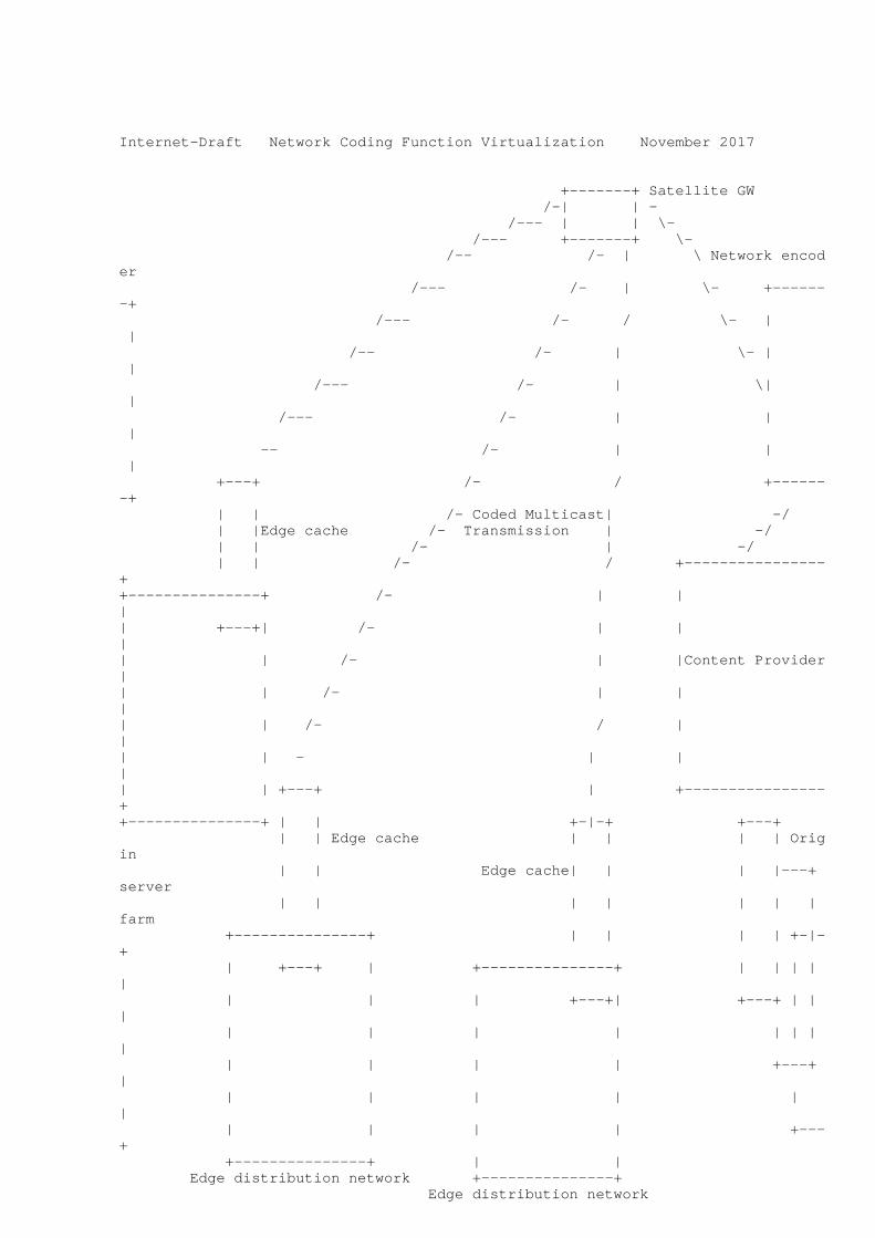
Internet-Draft Network Coding Function Virtualization November 2017
+-------+ Satellite GW /-| | - /--- | | \- /--- +-------+ \- /-- /- | \ Network encoder /--- /- | \- +-------+ /--- /- / \- | | /-- /- | \- | | /--- /- | \| | /--- /- | | | -- /- | | | +---+ /- / +-------+ | | /- Coded Multicast| -/ | |Edge cache /- Transmission | -/ | | /- | -/ | | /- / +----------------++---------------+ /- | | || +---+| /- | | || | /- | |Content Provider|| | /- | | || | /- / | || | - | | || | +---+ | +----------------++---------------+ | | +-|-+ +---+ | | Edge cache | | | | Origin | | Edge cache| | | |---+ server | | | | | | | farm +---------------+ | | | | +-|-+ | +---+ | +---------------+ | | | | | | | | +---+| +---+ | | | | | | | | | | | | | | | +---+ | | | | | | | | | | | +---+ +---------------+ | | Edge distribution network +---------------+ Edge distribution network

Figure 2: The SHINE use case
The system components which are of uttermost importance in this document, in view of the observation that they can highly benefit from the effective utilization of Network Coding as a Virtual Network Function are analyzed in further detail in the following.
The source encoder is a software module implementing the main logic behind the proposed coded multicast technique. It is in charge of
A. Vazquez-Castro, et al. Expires May 20, 2018 [Page 12]

Internet-Draft Network Coding Function Virtualization November 2017
transforming the original content and applying the required transformations in order to arrive at a representation format that is suitable for the subsequent coded multicast transmission. The component in question has indeed to look after both the cache population phase and the actual content delivery phase. The cache population phase envisages that the edge caches pre-fetch some content, based on appropriate functions of the content library, as well as on information about estimated future users’ demand for content. During the delivery phase, on the other hand, the source forms a multicast "codeword" to be transmitted over the shared link in order to meet the actual users’ content demands. As already stated, we envisage that the cache population phase is carried out through transmission (over the satellite core network connecting source node with edge caches) of content chunks. As to the content delivery phase, it takes place through DVB-encapsulated transmission, over the satellite network, of coded multicast frames.
Satellite Core Network is the network segment that basically interconnects the Source Encoder, which produces and processes multimedia contents, and several Edge Networks, where the in-network caches represent the boundary network elements. The satellite network trunk leverages standard DVB-S or DVB-S2 broadcast
The delivery phase hence occurs after the placement phase, when traffic is high and network resources are scarce and expensive (e.g., in the evening). At the beginning of this phase, each user reveals its request for one of the m files. The server is informed of these K requested files. In response, the server sends RF bits (or the equivalent of R files) over the shared link. The number R is called the rate of the server transmission or equivalently load of the satellite link. From the server transmission and its local cache content, each user needs to be able to recover their requested files. As already anticipated, SHINE looks after both the content placement and delivery phases. The objective is to minimize the rate R with which every possible set of user demands can be satisfied. The constraints are the storage limit during content placement and the recovery requirement during content delivery. Both phases are generic for both coded and uncoded schemes, but naively performed in the uncoded case. In fact, when relying on uncoded or naive multicasting during the delivery phase, it is well known that the optimal caching strategy is to cache the top M most popular files at each user cache. Though, this is in general far from optimal when coding can be used in the delivery phase. Thanks to the adoption of the dynamically provided Virtual Network Coding Function, SHINE discloses the potential of caching-aided code design and illustrates its major advantages compared to the optimal caching policy under uncoded (naive) multicasting. In a nutshell, the designed architecture shows how the combined use of edge caching and coded
A. Vazquez-Castro, et al. Expires May 20, 2018 [Page 13]

Internet-Draft Network Coding Function Virtualization November 2017
multicasting represents a promising approach to simultaneously serve multiple unicast demands via coded multicast transmissions, leading to order-of-magnitude bandwidth efficiency gains.
5. Conclusions
This memo presents a preliminary version of proposal for the design of NC as a network function. It is also discussed that it can be virtualized and integrated into a NFV architecture.
6. Differences with respect to version -01
Major restructuring of section 3.
7. Acknowledgements
The authors want to thank Dr. Harald Skinnemoen for useful comments and discussions. The first author wants to thank Dr. Carlos J. Bernardos and Luis M. Contreras for useful discussions.
The authors also want to acknowledge the following ongoing projects.
1. GEO-VISION - GNSS driven EO and Verifiable Image and Sensor Integration for mission-critical Operational Networks. EU funded project under the call H2020-GALILEO-2014-1 by the European Global Navigation Satellite Systems Agency (project reference 641451).
2. SatNetCode - Satellite Network-Coding for high performance, semantic-aware mission-critical visual communications. This project is funded by the European Space Agency, under contract No. 4000115046/15/NL/US.
3. HENCSAT - Highly Efficient Network Coding for Satellite Applications Test-bed. This project is funded by the European Space Agency, under contract No. 4000118143/16/NL/EM.
4. SHINE - Secure Hybrid In Network caching Environment. This project is funded by the European Space Agency, under Contract No. 4000118273/16/NL/CLP.
8. IANA Considerations
This memo includes no request to IANA.
A. Vazquez-Castro, et al. Expires May 20, 2018 [Page 14]

Internet-Draft Network Coding Function Virtualization November 2017
9. Security Considerations
This memo includes no Network Coding Function Virtualization - specific security definitions yet.
10. References
10.1. Normative Information References
[etsi_gs_nfv_002_v1.2.1] "Network Function Virtualisation (NFV); Architectural Framework", 2014.
[etsi_nvf_whitepaper] "Network Functions Virtualisation (NFV). White Paper 2", 2014.
[I-D.irtf-nwcrg-network-coding-taxonomy] Firoiu, V., Adamson, B., Roca, V., Adjih, C., Bilbao, J., Fitzek, F., Masucci, A., and M. Montpetit, "Network Coding Taxonomy", draft-irtf-nwcrg-network-coding-taxonomy-01 (work in progress), October 2016.
[RFC6363] Watson, M., Begen, A., and V. Roca, "Forward Error Correction (FEC) Framework", RFC 6363, 2011.
10.2. Conceptual ground basis
[AHL00] Ahlswede, R., Cai, N., Y. R. Li, S., and R. W. Yeung, "Network information flow", in IEEE Trans. Inform. Theory, vol. 46, pp. 1204-1216, July 2000.
[KOE03] Koetter, R. and M. Medard, "An algebraic approach to network coding", in IEEE/ACM Trans. on Networking, vol. 11, n. 5., pp. 782-795, October 2003.
[LI03] Y.R.Li, S., W. Yeung, R., and N. Cai, "Linear network coding", in IEEE Trans. Inform. Theory, vol. 49, n. 2., pp. 371-381, February 2003.
10.3. Application references
[ALE13] Alegre-Godoy, R. and M. A. Vazquez-Castro, "Spatial Diversity with Network Coding for ON/OFF Satellite Channels", in IEEE Communications Letters, vol. 17, No. 8, pp. 1612-1615, August 2013.
A. Vazquez-Castro, et al. Expires May 20, 2018 [Page 15]

Internet-Draft Network Coding Function Virtualization November 2017
[ALE15] Alegre-Godoy, R. and M. A. Vazquez-Castro, "Network Coded Multicast over Multi-beam Satellite Systems", in Mathematical Problems in Engineering, vol. 2015, Article ID 364234, May 2015.
[DO16.1] Do-Duy, T. and M. A. Vazquez-Castro, "Design of Virtualized Network Coding Functionality foR Reliability Control of Communication Services over Satellite", submitted to Special Issue on Network Coding. International Journal of Satellite Communications and Networking, 2016.
[Do16.2] Do-Duy, T. and M. A. Vazquez-Castro, "Network coding function virtualization", in IEEE 17th International Workshop on Signal Processing Advances in Wireless Communications (SPAWC), September 2016, INVIED PAPER.
[HAN15] Hansen, J., E. Lucani, D., Krigslund, J., Medard, M., and F. H. P. Fitzek, "Network coded software defined networking: enabling 5G transmission and storage networks", in IEEE Communications Magazine, 2015.
[HEI09] Heide, J., V. Pedersen, M., H. P. Fitzek, F., and T. Larsen, "Network Coding for Mobile Devices - Systematic Binary Random Rateless Codes", in ICC Workshops, 2009.
[SAX15] Saxena, P. and M. A. Vazquez-Castro, "DARE: DoF-Aided Random Encoding for Network Coding over Lossy Line Networks", in IEEE Communications Letters, vol. 19, No. 8, pp. 1374-1377, August 2015.
[SZA15] Szabo, D., Nemeth, F., Sonkoly, B., Gulyas, A., and F. H. P. Fitzek, "Towards the 5G revolution: A software defined network architecture exploiting network coding as a service", in SIGCOMM Comput. Commun, 2015.
[VAZ15.1] A. Vazquez-Castro, M., "A Geometric Approach to Dynamic Network Coding", in Information Theory Workshop, Jeju, Korea, October 2015.
[VAZ15.2] A. Vazquez-Castro, M., "Subspace coding over Fq-linear erasure satellite channels", in 12th International Symposium on Wireless Communication Systems, pp. 216-220, August 2015.
A. Vazquez-Castro, et al. Expires May 20, 2018 [Page 16]

Internet-Draft Network Coding Function Virtualization November 2017
[VAZ15.3] A. Vazquez-Castro, M. and P. Saxena, "Network Coding over Satellite: From Theory to Design and Performance", in Volume 154 of the series Lecture Notes of the Institute for Computer Sciences, Social Informatics and Telecommunications Engineering, pp. 315-327, September 2015, INVITED PAPER.
Authors’ Addresses
M.A. Vazquez-Castro Autonomus University of Barcelona Campus de Bellaterra Barcelona, 08391 Spain
Email: [email protected]
Tan Do-Duy Autonomus University of Barcelona Campus de Bellaterra Barcelona, 08391 Spain
Email: [email protected]
Simon Pietro Romano University of Napoli Federico II Via Claudio 21 Napoli, 80125 Italy
Email: [email protected]
Antonia Maria Tulino University of Napoli Federico II Via Claudio 21 Napoli, 80125 Italy
Email: [email protected]
A. Vazquez-Castro, et al. Expires May 20, 2018 [Page 17]