internship report at fatima fertilizer company limited -3-
TRANSCRIPT

Internship
Report at Fatima Fertilizer Company Limited(FFCL)
OFFSITE & UTILITIES(FFCL) By: Muhammad Mudasser

Internship Report
OFFSITE AND UTILITIES (FFCL) Page 2
Internship at Fatima Fertilizer Company Limited
Department: Production Department (Offsite and Utilities)
Mentor: Mr. Waheed Ashraf (Senior Engineer)
Duration:7-25 July, 2014
Submitted to: Chemical Engineering Department CIIT
Lahore
Submitted by: Name: Muhammad Mudasser
Reg #:SP11-BEC-051
Course: B.Sc. Chemical Engineering
Institute: COMSATS Institute of Information Technology
Lahore
Email: [email protected]
Contact #: 03316634393
Internship Report
OFFSITE AND UTILITIES (FFCL) Page 3
Acknowledgement
First and foremost I would like to express my thanks to Almighty ALLAH
because of His love and strength I was able to complete my internship report.
Completion of this report was a daunting task. However, it would not have been
possible without the kind support and help of many individuals. I would like to
extend my sincere thanks to all of them.
I am highly indebted to Mr. Rehman Hanif (Production Manager) for assigning
me Offsite and Utilities unit for my internship and providing me his valuable
guidance. I would also like to thank Mr. Ahsan Sarfraz (Unit Manager). A
special gratitude I give to my mentor Mr. Waheed Ashraf for his constant
supervision as well as for providing me information regarding the internship
plan. His support and encouragement helped me a lot. Furthermore I would also like to acknowledge with much appreciation the crucial
role ofthe staff of O&Uunit for giving me an opportunity to learn in a nice and pr
ofessionalenvironment.
My thanks and appreciations also go to my parents who have always helped me
and prayedfor my success and sincere friends who have willingly helped me ou
t with their abilities.
Internship Report
OFFSITE AND UTILITIES (FFCL) Page 4
Table of Contents
Company Overview 7 Main Products 7 Intermediate Products 7 Vision and mission 8 SAFETY ORIENTATION 9 FFCL HSE POLICY 10
To Protect 10
To Comply 10
To Strive For 10
HSE MISSION 10 IMS POLICY 11
OFFSITE AND UTILITIES (O & U) 12 Abstract 13
UTILITY STEAM GENERATOR (USG) 14 Boiler 16 Types of boilers 16
Fire tube boilers 16
Water tube boilers 17
FFCL Boiler 18 D-type Water tube Boiler 18 Main components of a Boiler 19 Energy Saving Devices 21
Economizers 21
Air pre-heaters 21
Oxygen Trim Controls 22
Boiler Feed Water (BFW) 22 De-aerator 22 De-aeration Purpose 22 De-aeration types 23
Mechanical De-aeration 23
Chemical De-aeration 23 Chemicals Added 24
Hydrazine 24
Ammine 24
Phosphate 24
Steam Generation 24 Thermosyphenoning 24
Continuous Blow Down 25
Intermittent Blow Down 25
Block Flow Diagram of Boiler 26 Different Analysis and their Ranges 27 Unburned Fuel Analyzer 27

Internship Report
OFFSITE AND UTILITIES (FFCL) Page 5
BMS TIMERS 28 Boiler Tripping Factors 28
Power Generation 29 Gas Turbine 29 FFCL Gas Turbine Model 29 Sections of Gas Turbine Generator 30 Basic Operation 32 Gas Turbine Working 32 Brayton Cycle 34 FFCL Turbine Description 35
Operation 35
Operating Mode 36
Control System 36
V-PRO (Protection Guard) 36
Lube Oil 37
Generator winding cooling system 37
Auxiliary and other compartment cooling System 37
Diesel Engine cooling 37
Vibration 37 Types 37
Radial vibration range 37
Axial Vibration Range 38
Seismic vibration range 38
ELMS 38 Factors affecting the gas turbine efficiency 39 Gas turbine Protection System 39 Difference b/w gas turbine and steam turbine 40 Causes of turbine Tripping 40
Heat Recovery Steam Generator 41 Major parts of HRSG and their Function 42 Chemical Dosing 44 Flue gases by pass System 44 Lab Analysis and their Ranges 44 Tripping Factors of HRSG 44
Cooling Towers 45
Introduction 46 Cooling Tower Types 46
Natural Draft 46 Mechanical Draft 46
Forced Draft 46
Induced Draft 47

Internship Report
OFFSITE AND UTILITIES (FFCL) Page 6
Fatima Fertilizer Cooling Tower 48 Pumps 48 Components of Cooling Tower 48 Working Principle 49 Water Losses 49 Make-up Line 49 Side Stream Filters 49 Cooling Tower Performance 49 Factors affecting Cooling Tower Performance 50 Problems occurs in Cooling Tower 50
References 52

Internship Report
OFFSITE AND UTILITIES (FFCL) Page 7
Company Overview
The Fatima Fertilizer company Limited was incorporated on December 24,
2003, as a joint venture between two major business groups in Pakistan
namely, Fatima Group and Arif Habib Group
The Complex has a 56MW captive power Plant in addition to off-sites and
utilities. The Complex has been allocated 110 MMCFD of gas from the
dedicated Mari Gas fields.
Foundation stone was laid on April 26, 2006 by the then Prime Minister of
Pakistan. The construction of the Complex commenced in March 2007 and is
housed on 950 acres of land.
The Complex, during its construction phase engaged over 4,000 engineers and
technicians from Pakistan, China, USA, Japan and Europe.
The Complex provides modern housing for its employees with all necessary
facilities. This includes a school for children of employees and the local
community, a medical centre and sports facilities.
Main Products
The complex main products are Urea, Calcium Ammonium Nitrate (CAN) &
Nitro phosphate (NP), intermediate products are Ammonia & Nitric Acid.
These products are divided into two parts, North side and South side products.
The production of complex is listed below:
Products Production(TPD) Percentage Urea 1500 40%
Calcium Ammonium Nitrate
1400 32%
Nitro Phosphate 1200 28%
Intermediate Products
Products Production(TPD) Ammonia 1500 Nitric Acid 1400
Internship Report
OFFSITE AND UTILITIES (FFCL) Page 8
Vision and mission Vision:
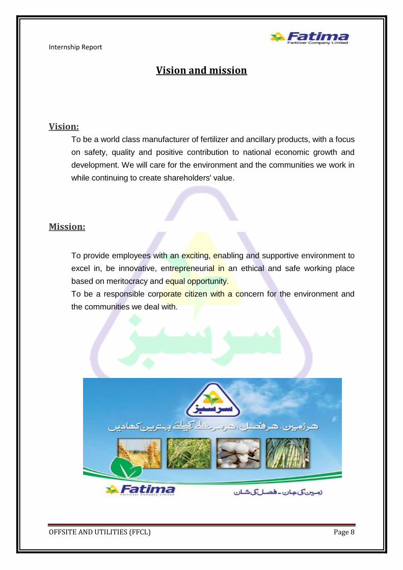
To be a world class manufacturer of fertilizer and ancillary products, with a focus
on safety, quality and positive contribution to national economic growth and
development. We will care for the environment and the communities we work in
while continuing to create shareholders' value.
Mission:
To provide employees with an exciting, enabling and supportive environment to
excel in, be innovative, entrepreneurial in an ethical and safe working place
based on meritocracy and equal opportunity.
To be a responsible corporate citizen with a concern for the environment and
the communities we deal with.

Internship Report
OFFSITE AND UTILITIES (FFCL) Page 9
SAFETY ORIENTATION Safety awareness is taught from the first moment you step into a plant. At the
start of our training program we were given a Safety Orientation. We were made
aware of all the hazards and safety issues. And I also participated in D level
talks on each Tuesday.
Some safety terms and equipment’s are as follows:
1. PPE (Personal Protection Equipments):
Helmet
Ear Plugs
Safety Shoes
Safety Glasses
2. Emergency Sirens: Level 1
Level 2
3. Assembly Point 4. Wind Socks 5. Masks 6. Fire Extinguishers 7. Caution Tapes 8. Safety Showers 9. Fire Hydrants 10. Emergency Drills 11. Medical Aid / First Aid 12. Permit system 13. Environmental awareness

Internship Report
OFFSITE AND UTILITIES (FFCL) Page 10
FFCL HSE POLICY
Human safety and Environmental conservation is our priority and shall not be
compromised as a result of business pressures. Our goal is to achieve
excellence in Health Safety and
Environment and become a benchmark for industry.
In pursuit of this goal we are committed:
To Protect:
All persons involved in our activities, employees, customers, suppliers and
community.Environment in which we operate.Business assets and reputation of
Fatima Fertilizer Company Limited.
To Comply:
Fully with all relevant HSE laws and regulations of the country.
To Strive For:
Annual improvements in our HSE performance.
The 'well-being' and Safety of our employees
Reducing and minimizing the production of waste
Social acceptance of our business.
HSE MISSION "Raise and maintain HSE standards at Fatima - in lines with International
recognized and Industry-Best Practices that prevent serious accident, minimize
harm and exposure to people, promote environment sustainability and protects
plant & equipment. To further develop and achieve a recognized Quality
Management Systems (QMS) Accreditation to ISO Health, Safety &
Environment & Process Safety Management standards with a culture of
Responsible Care and Behavioral Based Safety approach."

Internship Report
OFFSITE AND UTILITIES (FFCL) Page 11
IMS POLICY
Fatima Fertilizer Company Limited (FFCL) is committed to enhance country’s
agricultural growth and economy by manufacturing quality fertilizer products and
attaining excellence in all areas of its functions. We are also committed to
maintain safe and pollution free environment in the area.In order to achieve our
objectives the management and the employees of the company are dedicated
to comply with all applicable national and international standards, laws
regulation on Quality, Health, Safety & Environment.We further commit
ourselves to achieve full customer satisfaction and meet legal and moral
obligations through coordinated efforts and continual improvement in the
system.

Internship Report
OFFSITE AND UTILITIES (FFCL) Page 12
OFFSITE AND UTILITIES (O & U)

Internship Report
OFFSITE AND UTILITIES (FFCL) Page 13
Abstract
The objective of utility unit includes:
To provide desired quantity and quality of certain utilities to the ammonia,
urea, Nitric Acid, Nitro phosphate and CAN units for smooth functioning.
These utilities include electricity, cooling water, instrument air, fuel gas
and steam network.
Water, air and natural gas are the basic utility raw materials, which are
processed and improved in order to meet the plants’ criterion of quality and
ensure a longer life and safety of equipment.
Water Air Natural gas
Cooling water Instrument air Process stream
Steam Utility/service air Fuel stream
Drinking water Process air
Utility/service water
Utilities unit is a pre-requisite for other units because their smooth running
depends upon the utilities supplied by it. In case of utility failure plant has to face
an emergency shutdown.
O&Uinvolve many different sections, here we will discuss only following
sections:
1. USG (Utility Steam Generator)
2. GTG(Gas turbine Generator)
3. HRSG(Heat recovery Steam Generator)
4. Cooling Towers

Internship Report
OFFSITE AND UTILITIES (FFCL) Page 14
UTILITY STEAM GENERATOR (USG)

Internship Report
OFFSITE AND UTILITIES (FFCL) Page 15
Steam Generator:
The steam system generates Medium Pressure (MP), Low-Pressure and very
Low-Pressure (LLP) steam for the complex. Medium Pressure Steam at a
normal pressure of 43kg/cm2 and 390 deg C is generated by one USG and two
Heat Recovery Steam Generators (HRSGs).Steam condition of LP and LLP
steam are as follows;
LP: 18kg/cm2 350 deg C
LLP: 3.4kg/cm2 250 deg C
USG is a bottom support type natural
circulation water tube boiler with forced draft and the fuel is natural gas. The
capacity of USG is 75ton/hr.
In the event of any plant shutdown, excess
steam blow down is minimized by controlling of USG Facilities are provided to
dispose of excess LP & LLP steam to the condenser. Steam vent lines with
silencer are provided for MP header and 61kg/cm2 steam line from NA plant.
Steam is very useful and important in any industry. It provides and performs the
following functions:
Power Generation
Reforming Reaction
Running steam turbine
As a heating media

Internship Report
OFFSITE AND UTILITIES (FFCL) Page 16
Boiler A closed vessel in which
water is heated, steam is generated, steam is superheated, or any combination
thereof, under pressure or vacuum by the application of heat from combustible
fuels, electricity or nuclear energy.
Types of boilers:
Boilers systems are classified in a variety of ways.
They can be classified according to pressure, materials of construction.
Sometime boilers are classified by their heat source. For example they are often
referred to as oil-fired, gas-fired, coal-fired or solid fuel-fired boilers.
Boilers are classified into two major types:
1. Fire tube boilers:
Fire tube boilers consist of a series of straight tubes that are housed inside a
water-filled outer shell. The tubes are arranged so that hot combustion gases
flow through the tubes. As the hot gases flow through the tubes, they heat the
water surrounding the tubes. The water is confined by the outer shell of boiler.
To avoid the need for a thick outer shell fire tube boilers are used for lower
pressure applications.
Figure1: Fire tube Boiler
Internship Report
OFFSITE AND UTILITIES (FFCL) Page 17
Fire tube boilers typically have a lower initial cost, are more fuel efficient and
are easier to operate, but they are limited generally to capacities of 25 tons per
hour and pressures of 17.5 kg per cm2
2. Water tube boilers:
Water tube boilers are designed to circulate hot combustion gases around the
outside of a large number of water filled tubes. The tubes extend between an
upper header, called a steam drum, and one or more low headers or drums.
Because the pressure is confined inside the tubes, water tube boilers can be
fabricated in larger sizes and used for higher-pressure applications.Small water
tube boilers, which have one and sometimes two burners, are generally
fabricated and supplied as packaged units. Because of their size and weight,
large water tube boilers are often fabricated in pieces and assembled in the
field. In water tube or “water in tube” boilers, the conditions are reversed with
the water passing through the tubes and the hot gases passing outside the
tubes. These boilers can be of a single- or multiple-drum type. They can be built
to any steam capacity and pressures, and have higher efficiencies than fire tube
boilers.
Package water tube boilers come in three basic designs: A, D and O type. The
names are derived from the general shapes of the tube and drum
arrangements. All have steam drums for the separation of the steam from the
water, and one or more mud drums for the removal of sludge. Fuel oil-fired and
natural gas-fired water tube package boilers are subdivided into three classes
based on the geometry of the tubes.
The “A” design has two small lower drums and a larger upper drum for steam-
water separation. In the “D” design, which is the most common, the unit has two
drums and a large-volume combustion chamber. The orientation of the tubes in
a “D” boiler creates either a left or right-handed configuration. For the “O”
design, the boiler tube configuration exposes the least amount of tube surface
to radiant heat. Rental units are often “O” boilers because their symmetry is a
benefit in transportation.

Internship Report
OFFSITE AND UTILITIES (FFCL) Page 18
Figure2: Water Tube Boiler
FFCL Boiler
Type D type water tube
Company MACHHI(Italy)
Capacity 75ton/hr
Pressure 42kg/cm2
Draft Forced
Number of Burners 2
Number of Drums 2
Fuel Natural Gas
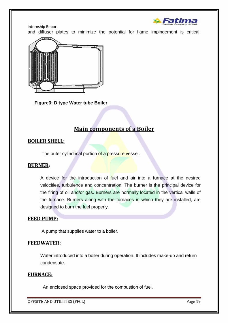
D type Water tube Boiler: “D” type boilers have the most flexible design. They have a single steam drum and a
single mud drum, vertically aligned. The boiler tubes extend to one side of each drum.
“D” type boilers generally have more tube surface exposed to the radiant heat than do
other designs. “Package boilers” as opposed to “field-erected” units generally have
significantly shorter fireboxes and frequently have very high heat transfer rates
(250,000 btu per hour per sq foot). For this reason it is important to ensure high-quality
boiler feed water and to chemically treat the systems properly. Maintenance of burners
Internship Report
OFFSITE AND UTILITIES (FFCL) Page 19
and diffuser plates to minimize the potential for flame impingement is critical.
Figure3: D type Water tube Boiler
Main components of a Boiler
BOILER SHELL:
The outer cylindrical portion of a pressure vessel.
BURNER:
A device for the introduction of fuel and air into a furnace at the desired
velocities, turbulence and concentration. The burner is the principal device for
the firing of oil and/or gas. Burners are normally located in the vertical walls of
the furnace. Burners along with the furnaces in which they are installed, are
designed to burn the fuel properly.
FEED PUMP:
A pump that supplies water to a boiler.
FEEDWATER:
Water introduced into a boiler during operation. It includes make-up and return
condensate.
FURNACE:
An enclosed space provided for the combustion of fuel.

Internship Report
OFFSITE AND UTILITIES (FFCL) Page 20
INSULATION:
A material of low thermal conductivity used to reduce heat losses.
SAFETY VALVE:
A spring loaded valve that automatically opens when pressure attains the valve
setting. Used to prevent excessive pressure from building up in a boiler.
SAFETY SHUT-OFF VALVE:
A manually opened, electrically latched, electrically operated safety shut-off
valve designed to automatically shut off fuel when de-energized.
WATER LEVEL:
The elevation of the surface of the water in a boiler.
STEAM SEPARATOR:
A device for removing the entrained water from steam.
Hand Holes:
They are steel plates installed in openings in Header to allow for inspection &
installation of tubes and inspection of Internal surfaces.
Low-Water cutoff:
It is a flat switch that is used to turn off the burner or shut off fuel to the boiler to
it from running once the water goes below a certain point.
De-Super Heater tubes or Bundles:
A series of tubes or bundle of tubes, in the water drum but sometime in the
steam drum that De-Super-heated steam. This is for equipment that do not
need dry steam.
Chemical Injection Line:
A connection to add chemicals for controlling feed water PH.

Internship Report
OFFSITE AND UTILITIES (FFCL) Page 21
Steam Drum:
A steam drum is a standard feature of a water-tube boiler. It is a reservoir of
water/steam at the top end of the water tubes. The drum stores the steam
generated in the water tubes and acts as a phase-separator for the steam/water
mixture. The difference in densities between hot and cold water helps in the
accumulation of the "hotter"-water/and saturated-steam into the steam-drum.
Mud Drum:
The water drum is larger than the header, but both are smaller than the steam
drum. The water drum equalizes the distribution of water to the generating
tubes. Both the water drum and the header collect the deposits of loose scale
and other solid matter present in the boiler water. Both the drum and the header
have bottom blow down valves. When these valves are opened, some of the
water is forced out of the drum or header and carries any loose particles with it.
SUPERHEATER:
The super heater consists of a super heater header and super heater elements.
Steam from the main steam pipe arrives at the saturated steam chamber of the
super heater header and is fed into the super heater elements. Superheated
steam arrives back at the superheated steam chamber of the super heater
header and is fed into the steam pipe to the cylinders. Superheated steam is
more expansive.
Energy Saving Devices
Several types of optional devices can be fitted to existing boilers to save energy:
Economizers:
Transfer a portion of the heat in the stack gases to water being fed to the boiler.
It is a heat exchanger installed in the exhaust stack that preheats the boiler feed
water.
Air pre-heaters:
Transfer heat from hot stack gas to air that is to be mixed with fuel for
combustion. This device saves energy by increasing the temperature of the
Internship Report
OFFSITE AND UTILITIES (FFCL) Page 22
mixture of fuel and air prior to combustion, so more of the heat of combustion is
available to heat water.
Oxygen Trim Controls:
Measure stack gas oxygen concentration and automatically adjust the inlet air
at the burner for optimum efficiency.
Boiler Feed Water (BFW)
Raw water after treatment stored in a polished water tank. Polished water is
pumped into de-aerator where dissolved gases oxygen/carbon dioxide is
removed mechanically and chemically.
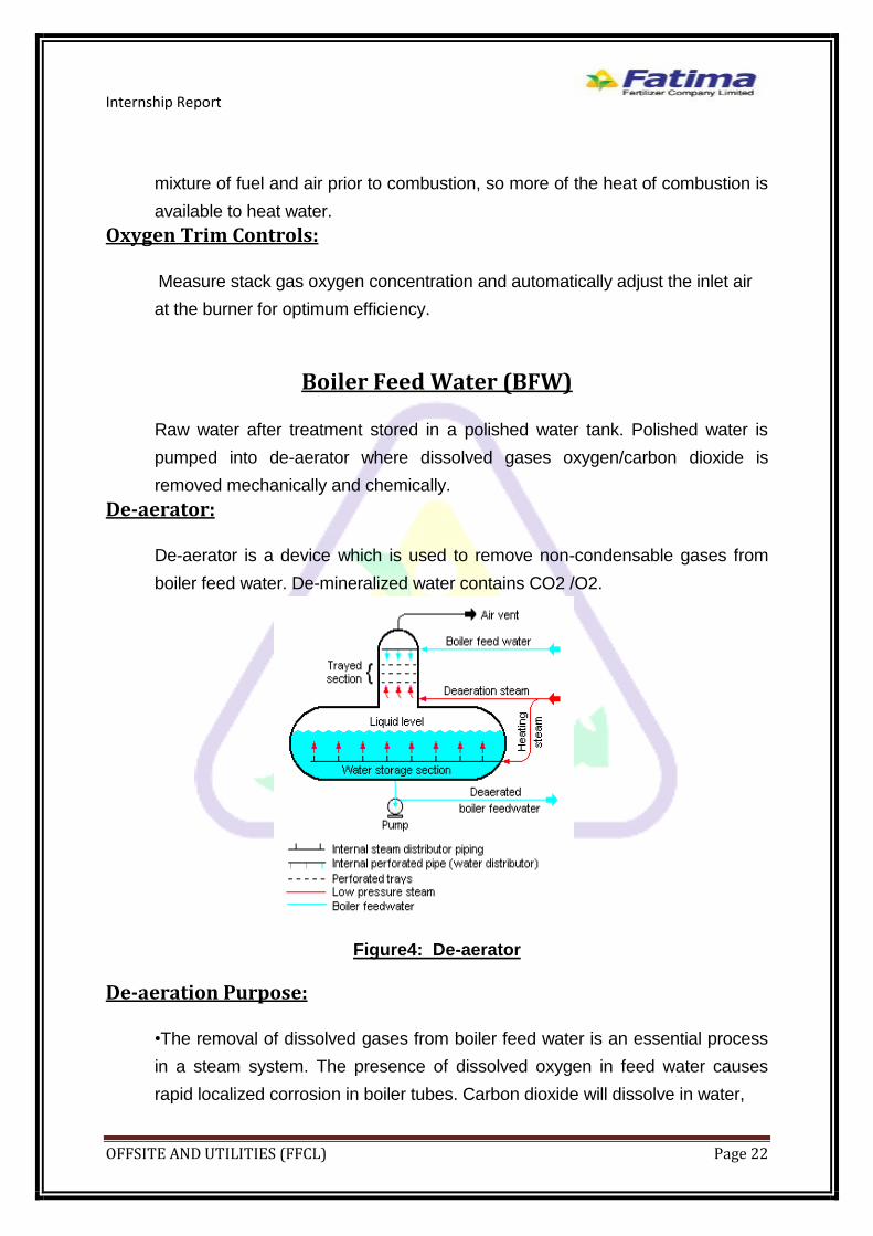
De-aerator:
De-aerator is a device which is used to remove non-condensable gases from
boiler feed water. De-mineralized water contains CO2 /O2.
Figure4: De-aerator
De-aeration Purpose:
•The removal of dissolved gases from boiler feed water is an essential process
in a steam system. The presence of dissolved oxygen in feed water causes
rapid localized corrosion in boiler tubes. Carbon dioxide will dissolve in water,
Internship Report
OFFSITE AND UTILITIES (FFCL) Page 23
resulting in low pH levels and the production of corrosive carbonic acid. Low pH
levels in feed water causes severe acid attack throughout the boiler system.
While dissolved gases and low pH levels in the feed water can be controlled or
removed by the addition of chemicals, it is more economical and thermally
efficient to remove these gases mechanically. This mechanical process is
known as de-aeration and will increase the life of a steam system dramatically.
•De-aeration is driven by the following principles: the solubility of any gas in a
liquid is directly proportional to the partial pressure of the gas at the liquid
surface, decreases with increasing liquid temperature; efficiency of removal is
increased when the liquid and gas are thoroughly mixed.
De-aeration types:
De-aerator perform de-aeration by two ways;
Mechanical de-aeration
Chemical de-aeration
Mechanical De-aeration:
Mechanical de-aeration works on the following principle/law
When water is heated at its saturation point or boiling point, the solubility
of gas in it decreases.
In De-aerator, the polished water is introduced and showered through nozzles
followed by trays to enhance the contact area.LPS is introduced and baffle is
placed in its path. As the LPS contact the polished water, its temperature
increases to boiling point and the solubility of dissolved gases reduces, these
gases exhaust through vent.
Chemical De-aeration:
The treated water then comes in accumulator where hydrazine N2H4 is
chemically dozed. From there all the remaining traces of oxygen are removed
by the following reaction
N2H4 + O2 N2 + H2O
Now this water is called de-aerated water or Boiler Feed Water BFW.

Internship Report
OFFSITE AND UTILITIES (FFCL) Page 24
This accumulator has a very large storage capacity (117ton/hr) .It can provide
water supply to the boiler for 10 min if water coming is stopped.
Chemicals Added:
Following chemicals are added;
Hydrazine:
Hydrazine is added in accumulator below the de-aerator to remove the
remaining traces of oxygen chemically.
Ammine:
Amine solution is added in the discharge line of BFW from accumulator
to control the PH.
Phosphate:
Phosphate is added in steam drum to control the PH and to control
the scale forming due to TDS.
Steam Generation
Natural gas comes inside through yellow line and air is blown through forced
draft fan which is a simple fan. It sucks the air from atmosphere. This air and
fuel (natural gas) come in burner where they burn and produce heat of
combustion which heats the tubes through convection.The tubes are placed
vertically and are called down comers. They are connected with steam drum at
upside and mud drum at down side. There are two burners for the heating of
tubes. They are placed in two directions horizontally. First of all the BFW enters
in the economizer. Here the waste combustion gases heat the BFW in the
economizer and raise the temperature of BFW. Then this heated water enters in
the steam drum. Here the phenomenon of thermosyphenoning takes place.
Thermosyphenoning:
When the density of water is high, it moves downward and when its density is
low it moves upward. This means, cold fluid moves downward and hot fluid
moves upward.The cold water in the steam drum goes downward through the
tubes in the mud drum. The tubes are heating so the water becomes hot and
also steam formed. This hot water and steam rises in the steam drum. Again the
Internship Report
OFFSITE AND UTILITIES (FFCL) Page 25
colder water goes down and steam and hot water raises upward and this
process continue. When this mixture of steam and hot water enters in the steam
drum, it passes through the baffle, after striking the baffle water and salts settle
down while steam rises up. The level of steam drum is maintained. The steam is
separated from water through primary and secondary screens which make the
steam pure and water free. This steam then goes to primary super heater where
it’s more heated then its temperature and pressure are maintained through de-
super heater. Then it passes through secondary super heater where it’s again
heated and its temperature reaches to 390o and pressure is 42kg/cm2.Now MP
steam is ready for operation at different sections where it requires.
Continuous Blow Down:
This installed at the boiler water level. Due to pH and chemical addition, salt
float at the surface of water and removed by continuous blow down.
Intermittent Blow Down:
This is at the bottom of boiler, when the amount of silica increases we partially
replace water and remove silica through this intermittent blow down. Normally
this point remains in closed position.

Internship Report
OFFSITE AND UTILITIES (FFCL) Page 26
Block Flow Diagram of Boiler
Polished water tank
Deaerat-orr
Accumul-ator
1
2
3
Economi-zer
Steam Drum
SuperHeater
De-SuperHeater
SuperHeater
MudDrum
RISEr
Downcomer
Combust-ion Chamber
Knock-out Drum
M
FDFan
STLPS
LLPS
AIRINTAKE
NATURALGAS
Flue Gases
Stack160*C
MPS Header
Amine Injection
Hydrazine
DrainDrain
IBDC
BD
LPS
Polished Water Pump
BFWPump
LLPS
Phosphate Injection
3bar,250 degree celcius
300*C
Polished Water Tank:9-TK-1306Polished Water Pump:9-P-1315BFW Pump:9-P-1502A/BHydrazine Tank:9-TK-1542Hydrazine Pumps:P-1542A/B
Amine Tank:9-TK-1543Amine Pumps:P-1543A/BPhosphate Tank:9-TK-1240Phosphate Pumps:P-1242A/BKnock Out Drum:9-D-15900
FD Fan:9-C-1550CBD Tank:9-D-1550IBD Tank:9-D-1551
Figure5:Block flow Diagram of Boiler
1:Ammonia Condensate2:Urea Condensate3:STM Condensate

Internship Report
OFFSITE AND UTILITIES (FFCL) Page 27
Different Analysis and their Ranges
BFW Parameter PH COND SiO2 Hydrazine Fe
Range 9-9.5 2-4us/cm <10ppb 100-300ppb
<10ppb
USG CBD Parameter PH COND SiO2 PO4 Hydrazine Fe
Range 9.2-9.7 <100us/cm <1ppm 5-7ppm 100-300ppb
<20ppb
USG MPS Parameter PH COND SiO2 Fe
Range 8.5-9.5 <7us/cm <20ppb <10ppb
Unburned Fuel Analyzer:
Unburned fuel is analyzed at the stack by O2 analyzer. If O2 in flue gases
leaving the stack is nil that indicate the fuel is not completely burned, black
smoke also indicate that fuel is not completely burned. If fuel is not completely
burned the consumption of fuel increases and efficiency of boiler decreases.

Internship Report
OFFSITE AND UTILITIES (FFCL) Page 28
BMS TIMERS Purge Time 5MIN
Waiting time for Air Trip Time 5MIN
Natural Draft Time 15MIN
Leak Test Time 2MIN
Pilot Re-Light Interval Time 1MIN
Burner Re-Light Interval Time 1MIN
Pilot Burner-2 Re-Light Interval 1MIN
FG Burner Re-Light Interval 1MIN
Boiler Tripping Factors
LL Combustion Air Flow LL Steam Drum Level
HH Furnace Pressure Loss Of All Flames
All Fuel Input Zero LL FD Fan Speed
LL FG To Burner Pressure HH FG To Burner Pressure
EMERGENCY SHUTDOWN ACTIVATED

Internship Report
OFFSITE AND UTILITIES (FFCL) Page 29
Power Generation
For the aid of power generation, there are two gas turbine generators in FFCL.
Gas Turbine The gas turbine is an internal combustion engine that uses air as the working
fluid. The turbine extracts thermal energy from fuel and converts it to
mechanical energy using the gaseous energy of the working fluid (air) to drive
the generator, which convert mechanical energy into electrical energy. A gas
turbine, also called a combustion turbine, is a type of internal combustion
engine. It has an upstream rotating compressor coupled to a downstream
turbine, and a combustion chamber in-between.
Gas turbines are a type of internal combustion engine in which burning of an air-
fuel mixture produces hot gases that spin a turbine to produce power. It is the
production of hot gas during fuel combustion, not the fuel itself that the gives
gas turbines the name. Gas turbines can utilize a variety of fuels, including
natural gas, fuel oils, and synthetic fuels. Combustion occurs continuously in
gas turbines, as opposed to reciprocating IC engines, in which combustion
occurs intermittently.
FFCL Gas Turbine model Company General Electric(USA)
Type Single Shaft
Model MS-5001-PA
Compressor Axial, Multistage(17)
Shaft Rotation Counter Clockwise
Turbine Speed 5100rpm
Generator Speed 1500rpm
Design Capacity 26.2MW/Each Turbine
Fuel Natural Gas
Controlling System Mark-6

Internship Report
OFFSITE AND UTILITIES (FFCL) Page 30
Sections of Gas Turbine Generator:
1. The inlet section (Air Suction)
2. The compressor section
3. The combustion section (the
combustor)
4. The turbine
5. Exhaust and
6. Generator
Inlet:
The air inlet duct must provide clean and unrestricted airflow to the turbine.
Consideration of atmospheric conditions such as dust, salt, industrial pollution,
foreign Objects (birds, nuts and bolts), and temperature (icing conditions) must
be made when designing the inlet system.
Compressor:
The compressor is responsible for providing the turbine with all the air it needs
in an efficient manner. In addition, it must supply this air at high static pressures.
Axial compressors consist of rotating and stationary components. A shaft drives
a central drum, retained by bearings, which has a number of annular airfoil rows
attached usually in pairs, one rotating and one stationary attached to a
stationary tubular casing. A pair of rotating and stationary airfoils is called a
stage. The rotating airfoils, also known as blades or rotors, accelerate the fluid.
The stationary airfoils, also known as stators or vanes, convert the increased
rotational kinetic energy into static pressure through diffusion and redirect the
flow direction of the fluid, preparing it for the rotor blades of the next stage. The
cross-sectional area between rotor drum and casing is reduced in the flow
direction to maintain an optimum Mach number using variable geometry as the
fluid is compressed.
Internship Report
OFFSITE AND UTILITIES (FFCL) Page 31
Combustor:
Once the air flows through the diffuser, it enters the combustion section, also
called the combustor. The combustion section has the difficult task of controlling
the burning of large amounts of fuel and air. It must release the heat in a
manner that the air is expanded and accelerated to give a smooth and stable
stream of uniformly-heated gas at all starting and operating conditions. This task
must be accomplished with minimum pressure loss and maximum heat release.
In addition, the combustion liners must position and control the fire to prevent
flame contact with any metal parts.
Turbine:
The turbine converts the gaseous energy of the air/burned fuel
mixture out of the combustor into mechanical energy to drive the compressor,
driven accessories, and, through a reduction gear, the load. The turbine
converts gaseous energy into mechanical energy by expanding the hot, high-
pressure gases to a lower temperature and pressure. Each stage of the turbine
consists of a row of stationary vanes followed by a row of rotating blades. This is
the reverse of the order in the compressor. In the compressor, energy is added
to the gas by the rotor blades, then converted to static pressure by the stator
vanes. In the turbine, the stator vanes increase gas velocity, and then the rotor
blades extract energy. As the mass of the high velocity gas flows across the
turbine blades, the gaseous energy is converted to mechanical energy. Velocity,
temperature, and pressure of the gas are sacrificed in order to rotate the turbine
to generate shaft power.
Exhaust:
After the gas has passed through the turbine, it is discharged through the
exhaust. Though most of the gaseous energy is converted to mechanical
energy by the turbine, a significant amount of power remains in the exhaust gas.
This energy is used in Heat Recovery steam Generator for steam production.

Internship Report
OFFSITE AND UTILITIES (FFCL) Page 32
Generator: We know that for electricity generation, following components are required;
1. Magnet
2. Conductor
3. Relative Motion
Here DC supplied to the coil which magnetizes the outer conductor. As we
provide it motion, due to its motion the flux changes which induces the electricity
on the coils.
Basic Operation
The basic operation of the gas turbine is similar to that of the steam power plant
except that air is used instead of water. Fresh atmospheric air flows through a
compressor that brings it to higher pressure. Energy is then added by spraying
fuel into the air and igniting it so the combustion generates a high-temperature
flow. This high-temperature high-pressure gas enters a turbine, where it
expands down to the exhaust pressure, producing a shaft work output in the
process. The turbine shaft work is used to drive the compressor and other
devices such as an electric generator that may be coupled to the shaft.
Gas Turbine Working
Gas turbines are comprised of three primary sections mounted on the same
shaft: the compressor, the combustion chamber (or combustor) and the turbine.
The compressor can be either axial flow or centrifugal flow. Axial flow
compressors are more common in power generation because they have higher
flow rates and efficiencies. Axial flow compressors are comprised of multiple
stages of rotating and stationary blades (or stators) through which air is drawn in
parallel to the axis of rotation and incrementally compressed as it passes
through each stage.
The acceleration of the air through the rotating blades and diffusion by the
stators increases the pressure and reduces the volume of the air. Although no
heat is added, the compression of the air also causes the temperature to
increase.

Internship Report
OFFSITE AND UTILITIES (FFCL) Page 33
The compressed air is mixed with fuel injected through nozzles. The fuel and
compressed air can be pre-mixed or the compressed air can be introduced
directly into the combustor. The fuel-air mixture ignites under constant pressure
conditions and the hot combustion products (gases) are directed through the
turbine where it expands rapidly and imparts rotation to the shaft. The turbine is
also comprised of stages, each with a row of stationary blades (or nozzles) to
direct the expanding gases followed by a row of moving blades. The rotation of
the shaft drives the compressor to draw in and compress more air to sustain
continuous combustion. The remaining shaft power is used to drive a generator
which produces electricity. Approximately 55 to 65 percent of the power
produced by the turbine is used to drive the compressor. To optimize the
transfer of kinetic energy from the combustion gases to shaft rotation, gas
turbines can have multiple compressor and turbine stages.

Internship Report
OFFSITE AND UTILITIES (FFCL) Page 34
Gas turbine is basically based upon Bryton cycle.
Brayton Cycle
THE IDEAL CYCLE FOR GAS TURBINE ENGINES
• Gas turbines usually operate on
an open cycle.
• Fresh air at ambient conditions
is drawn into the compressor,
where its temperature and
pressure are raised.
• The high pressure air proceeds
into the combustion chamber, where the fuel is burned at constant pressure.
• The resulting high-temperature gases then enter the turbine, where they
expand to the atmospheric pressure while producing power.
• The exhaust gases leaving the turbine are thrown out (not recirculated),
causing the cycle to be classified as an open cycle.
A Closed-cycle Gas-turbine Engine:
. The open gas-turbine cycle
described above can be modeled
as a closed cycle by utilizing the
air-standard assumptions
The ideal cycle that the working
fluid undergoes in this closed
loop is the Bryton cycle, which is
made up of four internally
reversible processes:
1-2 isentropic compression (in a compressor) 2-3 Constant-pressure heat addition
Internship Report
OFFSITE AND UTILITIES (FFCL) Page 35
3-4 isentropic expansion (in a turbine) 4-1 Constant-pressure heat rejection
FFCL Turbine Description
Operation:
1st of all, the compressor sucks the air which is filtered from the filter house and
become the dust free. At the compressor inlet the pressure is very low about 1
atm. The compressor compresses the air and takes it pressure to 5-6 kg/cm2
and the temperature to 300-350o C. The compression is in 17 stages. Then the
compressed air goes to the combustion chamber. The air is introduced from
sides while fuel is introduced from the center. Here
the combustion reaction occurs and very high temperature flue gases produces.
Here the pressure remains the same while the temperature increases. These
flue gases go to the turbine, here the flue gases expand and the turbine rotates.
F, the rotation is about 5100 rpm. Here the vent gases from the turbine are still
of very high temperature (about 4000 C). So their heat is utilized in the heat
recovery steam generator. The rotation of the shaft is very high. It is controlled
by the reduction gear. Reduction gear reduces its rpm so that the generator can
bear and work on it. Generator operates at 1500 rpm and it generates the power
of about 26.2 MW/turbine.
Operating Mode: There are two operating modes:
ISOCH
DROOP
ISOCH:
ISOCH is auto operating mode in which fuel consumption is vary automatically
according to change in load.
DROOP:
DROOP is manually operating mode in which fuel consumption is vary
manually according to change in load.
If there is any problem in automatically operating mode, then fuel consumption
is vary manually.

Internship Report
OFFSITE AND UTILITIES (FFCL) Page 36
Capacity of each turbine is 26.2MW, but normal load on each turbine is 10-
11MW.
Control System:
Control system is MARK-6. It is speed tropic system which
respond in 40 millisecond. All parameters readings are received in three cards
RST, and then display on monitor screen, any command given by operator first
goes into these three cards and from these cards signals are transferred to the
operation field.
V-PRO (Protection Guard):
All turbine tripping signals are received in V-PRO and then turbine trip.
Lube Oil:
Lube oil is used for the lubrication of shaft and gear box. It is an important
aspect in turbine. Lube oil console is at the base of turbine. After lubrication its
temperature rises and cross a certain limit. It is important to control the
temperature of lube oil. From lube oil console, lube oil is send to the cooling
system, where it is cooled by air. After getting required temperature it is send
back to the lube oil console and used for lubrication.
Generator winding cooling system:
Winding of generator gets heated which may reduce the efficiency of
generator or sometime lead to failure of generator. Fans are used to cool
down the generator winding.
Auxiliary and other compartment cooling System:
To cool down the auxiliary, gear box and other compartments air is used which
is circulate by motor driven pumps.
Diesel Engine cooling:
To cool down the Diesel engine radiator is used through which water is circulate
to cool down the diesel engine.

Internship Report
OFFSITE AND UTILITIES (FFCL) Page 37
Vibration:
A vibration is the movement of shaft or misses aligning of the shaft. It takes
place in turbine, gear box and generator compartment. It is very critical
parameter in turbine. It may lead to the tripping of turbine.
Types:
Normally vibration is of two types;
Axial Vibration:
Axial vibration is along the x-axis of the shaft.
Radial vibration:
Radial Vibration is along the y-axis of the shaft.
Seismic Vibration:
Seismic vibration is the vibration of casing. It is more critical than the other
vibrations.
Radial vibration range:
Radial vibration range of different compartments is given below;
Gear box:
Alarming: 95um
Tripping: 133um
Turbine:
Alarming: 110um
Axial Vibration Range:
Axial vibration range of different compartments is given below;
Gear Box:
Alarming: -0.47-0.47mm
Tripping: -0.48-0.48
Turbine:
Alarming: -0.6-0.6
Seismic vibration range:
Seismic vibration range of different compartments is given below;
Turbine:
Alarming: 13mm/s
Tripping: 25mm/s
Generator:
Alarming: 4.10mm/s
Tripping: 6.7mm/s

Internship Report
OFFSITE AND UTILITIES (FFCL) Page 38
ELMS:
It stands for Electrical Load Management System
Here in utility section, there are two turbines which can generate 26.2, 26.2
MW each. But they take 11, 11 from both for the working of the whole FFCL.
It manages the load. If one turbine trips then it cut off township supply to
operate the plant smoothly and when the problem solves the supply continued.
Factors affecting the gas turbine efficiency
1-Ambient Temperature
If temperature is less, then we got dense air and efficiency increases.
2- Atmospheric Pressure
If it’s high then the turbine is more efficient
3-Intercooling
Intercooling is important for compressor. We perform cooling before next 0r a
number of stages because otherwise the compressor got high pressurized or
hot and can be damaged.
4-Affective Lubrication
The affective lubrication between the parts of the system increase its efficiency
5-Frictional loses
As they are less, turbine is efficient
5-Heat loses
Insulation should be proper to get minimum heat loses.
Gas turbine Protection System
Gas turbine should be run by keeping its limits in mind. If it exceeds its
limitations then alarm sounds and the system trips. So that we overcome any
more lose.
Following are the things which protect the Gas turbine for serious damage.
1-Flame Failure
Flame detectors are placed in the gas turbine. They are 2 in number, If one
fails then the alarm strikes but if other also fails then the turbine trips. It
actually tells that fire is happening or not.
Internship Report
OFFSITE AND UTILITIES (FFCL) Page 39
2-High Exhaust temperature
The flue gases vent design temperature is fixed. If the flue gases got more
temperature it melts and its live decreases.
3-Vibration
Vibration probes are placed. If the vibration of the bearings increases, it trips
the system.
4-Pressure of Flue gases
If pressure of flue gases increases, trips
6-Temperature Sensors
When temperature become unbearable, it trips the system.
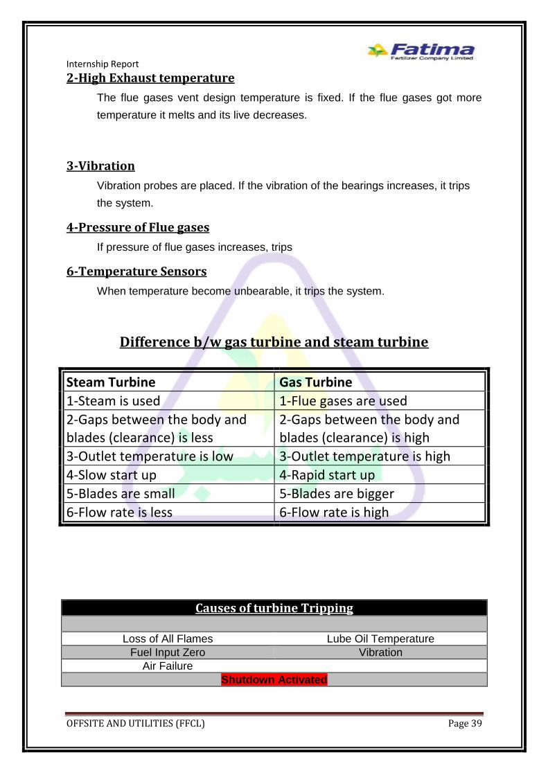
Difference b/w gas turbine and steam turbine
Steam Turbine Gas Turbine
1-Steam is used 1-Flue gases are used
2-Gaps between the body and blades (clearance) is less
2-Gaps between the body and blades (clearance) is high
3-Outlet temperature is low 3-Outlet temperature is high
4-Slow start up 4-Rapid start up
5-Blades are small 5-Blades are bigger
6-Flow rate is less 6-Flow rate is high
Causes of turbine Tripping
Loss of All Flames Lube Oil Temperature
Fuel Input Zero Vibration
Air Failure
Shutdown Activated
Internship Report
OFFSITE AND UTILITIES (FFCL) Page 40
HEAT RECOVERY STEAM GENERATOR

Internship Report
OFFSITE AND UTILITIES (FFCL) Page 41
Heat Recovery Steam Generator Heat recovery steam generator use exhaust from turbine and recover the heat
from the flue gases. Exhaust from the turbine has high temperature which is
utilized to produce the medium pressure steam. If steam is not required at
complex and USG fulfill the requirement of steam at complex the flue gases
from the turbine are passed through stack to atmosphere.
In FFCL there are two heat recovery steam generator at the end of each gas
turbine generator. Capacity of each heat recovery steam generator is 75ton/hr.
In the case of steam required or load is high at complex heat recovery steam
generator is used to produce the steam for complex.
Major parts of HRSG and their Function:
Economizer:
Economizer is used to recover the heat from flue gases at the
exhaust of heat recovery steam generator. First of all BFW water passes
through economizer and use the heat of flue gases to pre-heat the water.
From economizer flue gases send to stack and than to atmosphere.
Steam Drum:
A steam drum is a standard feature of a water-tube boiler and heat recovery
steam generator.. It is a reservoir of water/steam at the top end of the water
tubes. The drum stores the steam generated in the water tubes and acts as a
phase-separator for the steam/water mixture. The difference in densities
between hot and cold water helps in the accumulation of the "hotter"-
water/and saturated-steam into the steam-drum.
Evaporator:
From steam drum the water that is not converted into steam is send
to evaporator which act as riser and down comer. Evaporator also used the
heat of flue gases, and converts the water into steam. It is work on the basis of
density. As density decreases after heating steam move upward to steam
drum and water from steam drum having higher density moves downward into
evaporators.

Internship Report
OFFSITE AND UTILITIES (FFCL) Page 42
SUPERHEATER:
The super heater consists of a super heater header and super heater
elements. Steam from the main steam pipe arrives at the saturated steam
chamber of the super heater header and is fed into the super heater elements.
Superheated steam arrives back at the superheated steam chamber of the
super heater header and is fed into the steam pipe to the cylinders.
Superheated steam is more expansive. Super heater uses the heat of flue
gases. Flue gases first passes through super heater and give their heat to
convert the saturated steam into superheated.
De-Super Heater:
In de-super heater BFW is sprayed on superheated steam that
comes from first super heater. The purpose of de-super heater to make the
steam able to carry its heat for longer time. Finally steam passes through
second super heater and then send to medium pressure steam header.
Vent and silencer:
If the pressure of steam cross the limit to control the steam pressure vents are
installed from which steam is send to atmosphere and to minimize the noise
there are silencers.
Stack:
Stack is used to send the flue gases to atmosphere at temperature 160 degree
C.
Continuous Blow Down:
This installed at the boiler water level. Due to pH and chemical addition, salt
float at the surface of water and removed by continuous blow down. From
continuous blow down we get LLPS which send to LLPS header.
Intermittent Blow Down:
This is at the bottom of boiler, when the amount of silica increases we partially
replace water and remove silica through this intermittent blow down. Normally
this point remains in closed position.

Internship Report
OFFSITE AND UTILITIES (FFCL) Page 43
Chemical Dosing:
Following chemicals are added;
Hydrazine:
Hydrazine is added in accumulator below the de-aerator to
remove the remaining traces of oxygen chemically.
Ammine:
Amine solution is added in the discharge line of BFW from
accumulator to control the PH.
Phosphate:
Phosphate is added in steam drum to control the PH and to
control the scale forming due to TDS.
Flue gases by pass System:
There is a bypass system for flue gases in case of no
requirement of steam or maintenance of heat recovery steam generator. Flue
gases are passed through the stack of gas turbine.
Lab Analysis and their Ranges
HRSG A CBD
Parameter PH COND SiO2 PO4 Hydrazine Fe
Range 9.2-9.7 <100us/cm <1ppm 5-7ppm 100-300ppb
<20ppb
HRSG B CBD
Parameter PH COND SiO2 PO4 Hydrazine Fe
Range 9.2-9.7 <100us/cm <1ppm 5-7ppm 100-300ppb
<20ppb
HRSG A MPS
Parameter PH COND SiO2 Fe
Range 8.5-9.6 <7us/cm <20ppb <10ppb

Internship Report
OFFSITE AND UTILITIES (FFCL) Page 44
HRSG B MPS
Parameter PH COND SiO2 Fe
Range 8.5-9.7 <7us/cm <20ppb <10ppb
Tripping Factors of HRSG
Water level in steam drum All fuel input zero
Loss of all flames Low combustion air flow
EMERGENCY SHUTDOWN

Internship Report
OFFSITE AND UTILITIES (FFCL) Page 45
Cooling Towers

Internship Report
OFFSITE AND UTILITIES (FFCL) Page 46
Introduction
Cooling towers are a very important part of any chemical plant. They are used
to reject heat from a system to the atmosphere. The water containing heat
from the plant enters the cooling tower in which it contacts with the air and
mass & heat transfer occur. Then the cooled water from the cooling tower is
again sent to the plant to absorb more heat and this cycle continues.
Cooling Tower Types Cooling towers mainly fall into two categories:
1- Natural Draft
2- Mechanical Draft
Natural Draft In natural draft the air is introduced into the cooling tower by natural air flow.
No device is used to draw air into the cooling tower. Utilizes buoyancy via a
tall chimney. Warm, moist air naturally rises due to the density differential
compared to the dry, cooler outside air. Warm moist air is less dense than drier
air at the same pressure. This moist air buoyancy produces an upwards
current of air through the tower.
Mechanical Draft In Mechanical draft a fan is used to draw large flow rate of air inside the
cooling tower.The mechanical draft cooling towers are further categorized:
1.Forced Draft A mechanical draft tower with a blower type fan at the intake. The
fan forces air into the tower, creating high entering and low exiting air
velocities. The low exiting velocity is much more susceptible to recirculation.
With the fan on the air intake, the fan is more susceptible to complications due
to freezing conditions. Another disadvantage is
that a forced draft design typically requires more
motor horsepower than an equivalent induced
draft design. The benefit of the forced draft design
is its ability to work with high static pressure. Such
setups can be installed in more-confined spaces
and even in some indoor situations. This fan/fill
geometry is also known as blow-through.

Internship Report
OFFSITE AND UTILITIES (FFCL) Page 47
2- Induced Draft A mechanical draft tower with a fan at the discharge (at the top) which pulls
air up through the tower. The fan induces hot moist air out the discharge. This
produces low entering and high exiting air velocities, reducing the possibility of
recirculation in which discharged air flows back into the air intake. This fan/fin
arrangement is also known as draw-through.

Internship Report
OFFSITE AND UTILITIES (FFCL) Page 48
Fatima Fertilizer Cooling Tower In Fatima Fertilizer we have 12 units of induced draft counter flow cooling
tower type. This cooling tower circulates cooling water through the Ammonia,
Urea, NA, CAN, NP, NPK process units and offsite utilities. It has a designed
capacity to handle 49,000 m3/h of water returning from the plants and tower
basin has a capacity of 10,000 m3. It cools the water from 43 deg C to 32 deg
C.
Pumps: There are six motor driven centrifugal pumps and one turbine driven pump
which are used to supply cold water to the plant from cooling tower basin. The
designed discharge pressure of these pumps is 5 kg/cm2 but its operating
pressure is 4.4 kg/cm2. The capacity of the pumps is 9000 m3/hr but operating
at 8600 m3/hr.
Components of Cooling Tower 1- Frame & Casing: A frame of cooling tower support the casing, motor, fans and other components inside the cooling tower. The frame of our cooling tower is made of concrete and the casing is made up of fiber reinforced plastic (FRP). The FRP material is used because of its resistance to corrosion and they can handle heavy load of water. 2- Fill: A fill in a cooling tower is used to increase the contact time of air and water for the good transfer of heat. The fill can also be either film type or splash type. Film fill consists of closely space plastic surfaces over which water the water spreads and contacts with air. Film type provides more contact area. It is more compact and cost effective. In splash type, water falls over horizontal splash bars and breaks down into droplets and contacts with the air. It is mostly used for dirty water. We first had film type fill in our cooling tower but now we have splash type fill made up of PVC. The film type was changed due to biological growth between the surfaces which caused to choke the line. 3- Cold Water Basin: Cold water basin is at the bottom of the cooling tower and is used to collect the cooled water through the fill. Water is supplied to the plant from cold water basin through pumps. It has a capacity of 10,000 m3. 4- Drift Eliminators: Drift eliminators are used to capture the water droplets entrapped in the air stream. These are made up of PVC. The drift losses cannot be made zero. The drift losses in our cooling tower are 0.01% of water circulation rate. 5- Louvers: Louvers are used to direct air inside the cooling tower and to retain water inside the cooling tower. We have louvers made up of cement but we are not using them currently for better air flow. 6- Nozzles: These are used to shower water over the fill. The hot water from the plant through risers goes to the channel. Then it goes to the header and then finally it comes to the nozzles where it is showered on fill. The material of nozzles is PVC and each tower contain 360 nozzles.
Internship Report
OFFSITE AND UTILITIES (FFCL) Page 49
7- Fans: The fans used in cooling towers are of axial type. Each fan has 10 blades of FRP. Currently the fan’s pitch angle is 13.2 degree.
Working Principle The working principle of the cooling tower is based on the simultaneous heat and mass transfer. The hot water from the plant is entered the cooling tower and showered from the top on the fill through nozzles. The fresh air enters the cooling tower from bottom by induced force provided by fan on top of the cooling tower. The fresh air and hot water make contact with each other on the fill where heat and mass transfer occurs. Some of the water molecules having high energy are evaporated by receiving latent heat and remaining water gains sensible heat and lower its temperature. After this the cooled water falls in the water basin and collected. The air exits from top. Some of the air molecules are entrapped in the air and exit from cooling tower with the air. For such molecules we have drift eliminator above the nozzles which captures these molecules and they fall back in the cooling tower basin. Blow down line is for withdrawing some water from the circulating water to maintain the amount of salts and other impurities.
Water Losses: There are three type of water losses in a cooling tower: 1- Blow down losses 2- Evaporation losses 3- Drift losses ( 0.01% of circulating water)
Make-up Line: A make-up line is added to the system to compensate these water losses in the cooling tower. The make-up line is added to the system on the availability basis. • Make-up from Ahmed PurLamha • Dual Media Filter • Clarifier
Side Stream Filters: There are 8 side stream filters having a capacity of 2500m3/hr. A portion of water from the basin is sent to these filters to remove suspended solids from water in order to decrease the concentration of suspended solids in the cooled water. This filtered water is again sent to the cooling tower basin. The filter is back washed to remove these suspended solids from the sand and drained through disposal line.
Cooling Tower Performance The important parameters for determining the performance of a cooling tower are: 1- Range: It is the difference between the inlet water temperature and outlet water temperature. The designed range for our cooling tower is 11 deg C. 2- Approach: It is the difference between the outlet water (Cold water) temperature and wet bulb temperature. The designed approach of cooling tower is 5 deg C. Range and approach both indicate the performance of a cooling tower but approach is a better indicator for determining performance of a cooling tower. 3- Effectiveness: It is the ratio of range to the sum of range & approach. Effectiveness = (Range)/(Range+Approach)
Internship Report
OFFSITE AND UTILITIES (FFCL) Page 50
4- Cooling Capacity: It is the heat rejected from the system in Kcal/hr. It can be calculated by this formula:
Q = mCp(T2 – T1) Where Q= Heat rejected in Kcal/hr m= Mass flow rate of water Cp= Specific heat of water (T2 – T1)= Temperature difference between inlet and outlet stream of water 5- Evaporation Loss: It is the quantity of water that is lost by evaporation during cooling process of water. An empirical relation used to calculate it is: Evaporation Loss (m3/hr) = 0.00085 x 1.8 x circulation rate (m3/hr) x (T2 – T1) 6- Cycles of Concentration (C.O.C): It is the ratio of dissolved solids in circulating water to the dissolved solids in make-up water. 7- Blow Down: It is amount of water removed from the circulating water to decrease the concentration of salts. Blow down = Evaporation loss / (C.O.C – 1)
Factors affecting Cooling Tower Performance There are some factors by which we can control the performance of the cooling tower. These are explained below in detail: 1- Wind Direction:
The cooling towers we have are not designed according to the wind direction. The wind direction is mostly such that it draws back the exhaust air towards the inlet of air in the cooling tower. The wind direction is a main cause for recirculation.
2- Increased Humidity:
The second reason which controls the performance of cooling tower is the humidity of air. The increased humidity of air causes the air not to absorb more heat and moisture from the hot water in the cooling tower and thus reducing the performance of the cooling tower.
Problems occurs in Cooling Tower The cooling water quality is very important to be maintained. It can cause a lot of damage to the equipment used in plant if the quality is compromised. For example an increased amount of solids in cooled water can cause scaling the heat exchanger in the plant which can choke the line and damage the whole system. So we have to control the water quality to protect our system against these damages. Normally cooling water can cause four types of problem: 1- Corrosion:
It is the gradual destruction of metals by chemical reaction with its environment. Or we can say it is electrochemical oxidation of metals in reaction with some oxidant such as oxygen. It causes loss of metal thickness or even penetration of tube walls which can cause leakage of process fluids into the cooling water or vice versa.

Internship Report
OFFSITE AND UTILITIES (FFCL) Page 51
Corrosion is mostly characterized as general, localized and galvanic. General attack: exists when the corrosion is uniformly distributed over the metal surface. Localized attack (pitting): exists when only small areas of the metal corrode. Pitting is the most serious form of corrosion because the action is concentrated in small area. It may perforate the area in a short time. Galvanic attack: can occur when two different metals are in contact. The more active metal corrodes rapidly. To control corrosion we are adding a zinc and phosphate base chemical inhibitor suggested by NALCO and the chemical is referred as NALCO 129. 2- Scaling:
Scaling is the formation of dense coating of predominantly inorganic material formed from the precipitation of water soluble constituents. Scale results when dissolved ions in the water exceed the solubility of a given mineral. Some common scales are: • Calcium carbonate • Calcium phosphate • Magnesium silicate • Silica To prevent our system from scaling we are adding a chemical suggested by NALCO which is referred as NALCO 190. 3- Fouling:
Fouling is the accumulation of solid material, other than scale, in a way that hampers the operation of plant equipment or contributes to its deterioration. Example of common fouling factors are: • Dirt and silt • Sand • Corrosion products • Natural organics • Microbial masses

Internship Report
OFFSITE AND UTILITIES (FFCL) Page 52
To protect our system against fouling we are feeding a dispersant NALCO 8506. It keeps the fouling materials dispersed in the water and prevent them from sticking to the equipment. 4- Biological Growth:
The uncontrolled growth of micro-organisms can lead to deposit formation that contributes to fouling, corrosion and scale. Nutrients, atmosphere, location and temperature contribute to the microbial growth. We add hypochlorite and Bromine to the cooled water to protect our system against microbiological growth. The pH of the cooled water is controlled by H2SO4.
References http://www.fatima-group.com/fatimafertilizer/aboutus.php http://www.fatima-group.com/fatimafertilizer/companyoverview.php http://www.fatima-group.com/fatimafertilizer/healthsafety.php http://en.wikipedia.org/wiki/Cooling_tower http://en.wikipedia.org/wiki/Gas_turbine http://www.wartsila.com/en/gas-turbine-for-power-generation http://www.turbinetech.com/products-services/turbine-parts/general-electric/index.html Industrial Manual