internship report on manufacturing process of lead acid battery of
TRANSCRIPT

Undergraduate Internship Report
Department of Electrical and Electronic Engineering 1
INTERNSHIP REPORT
ON
MANUFACTURING PROCESS OF LEAD ACID BATTERY
OF
RAHIMAFROOZ BATTERIES LTD. (RBL)
By
Farzana Hossin-2008-2-86-030
Farhana Akther Zannat-2009-3-80-008
Submitted to the
Department of Electrical and Electronic Engineering
Faculty of Sciences and Engineering
East West University
In partial fulfillment of the requirements for the degree of
Bachelor of Science in Electrical and Electronic Engineering
(B.Sc. in EEE)
Spring 2013
Approved By
_____________________ ____________________
Academic Advisor Department Chairperson
Tahseen Kamal Dr. Mohammad Mojammel Al Hakim
Undergraduate Internship Report
Department of Electrical and Electronic Engineering 2
CERTIFICATE

Undergraduate Internship Report
Department of Electrical and Electronic Engineering 3
AUTHORIZATION LETTER
We declare that we are the sole authors of this internship report. We authorize East West
University to lend this internship report to other institutions or individuals for the purpose of
industrial attachment. We further authorize East West University to reproduce this internship
report by photocopy or other means, in total or in part, at the request of other institutions or
individuals for the purpose of industrial attachment.
_____________________ ____________________
Farzana Hossin Farhana Akther Zannat

Undergraduate Internship Report
Department of Electrical and Electronic Engineering 4
ACKNOWLEDGEMENT
At the very outset, we wish to convey our heartfelt gratitude to almighty Allah for His help to
complete the internship successfully. We also thank the management of Rahimafrooz Batteries
Ltd. for providing us with such opportunity to accomplish our industrial training in Rahimafrooz
Batteries Ltd. (RBL). We would specially like to thank Engr. S. M. Shamsul Farhan of RBL who
helped us to approve our internship application.
We want to thank all who helped to complete our internship successfully. In this process our
special thanks go to Engr. Subir Kumar Das (Engineering and Technical department), Engr Shah
Muntasir Mamun (Assebly department) and Engr. Saifuddin Mahamood (Plate Preparation
department) who coordinated our internship program and helped us to get acquainted with other
engineers. They helped us to learn the scheduled topic which was present in our internship
training schedule. We also want to thank each and every employee of RBL for their continual
support.
We would also like to mention the name of Dr. Mohammad Mojammel Al Hakim, Chairperson
and Associate Professor of the Department of Electrical and Electronic Engineering, East West
University (EWU) for his support and encouragement throughout the period of our internship.
We would like to give our gratitude to our honorable supervisor Ms. Tahseen Kamal, Senior
Lecturer, Department of Electrical and Electronic Engineering, East West University (EWU) for
giving her valuable time for us to complete this report successfully.
We also want to thank our parents and all of our friends for their moral support and their helpful
discussion during this work.
Undergraduate Internship Report
Department of Electrical and Electronic Engineering 5
EXECUTIVE SUMMARY
We completed our internship at Rahimafrooz Batteries Ltd. (RBL) located at West Panisail,
Zirani Bazar, Gazipur, Dhaka from 23rd December, 2012 to 8th January, 2013 (including Friday)
and this internship report is the result of those 15 days attachment with the Rahimafrooz Batteries
Ltd. (RBL). During our internship period we gathered practical experiences on topics related to
lead acid battery production, different mechanical equipment which we have theoretically learned
in Electrical Machine and Renewable Energy courses. In this report we have focused on the
manufacturing process of lead acid battery which is manufactured in Rahimafrooz Batteries Ltd.
(RBL).
Rahimafrooz Batteries Ltd. (RBL) manufactures around 200 types of automotive and customized
industrial batteries. With the help of the factory engineers we observed the production floor of
different sections, different machines such as grid casting machine, lead oxide mill, pasting
machine etc. and understood the manufacturing process of the lead acid battery.
We acquired knowledge about various types of batteries, charging and discharging process of
lead acid battery, manufacturing process of lead acid battery and were introduced with different
machines such as plastic molding machine, curing oven, Positive Dry Oven (PDO), Inert Gas
Oven (IGO) etc.

Undergraduate Internship Report
Department of Electrical and Electronic Engineering 6
TRAINING SCHEDULE
We completed our internship at Rahimafrooz Batteries Ltd. (RBL) from 23rd December, 2012 to
8th January, 2013 (including Friday). Each day we worked from 8 AM to 4 PM. Table 1
represents the training schedule of RBL.
Table 1: Internship Training Schedule at RBL.
Day Topic Trainer
Sunday
23.12.2012 Overview of the Factory.
Engr. Md. Abdur Raquib
Head of Supply Chain
Monday
24.12.2012 Overview of Smelting Section.
Engr. Md. Rafiqul Haque
Production Officer
Wednesday
26.12.2012
Overview of Engineering and
Technical Section.
Engr. Subir Kumar Das
Manager, Engineering
and Technical
Thursday
27.12.2012 Overview of Plastic Molding Section.
Engr. Abu Nasar M. Abdullah
Senior Executive
Friday-Tuesday
28.12.2012-
01.01.2013
Overview of Plate Preparation Section. Engr. Saifuddin Mahamood
Senior Executive
Thursday-Saturday
02.01.2013-
04.01.2013
Overview of Assembly Section. Engr. Shah Muntasir Mamun
Executive, Production
Sunday
05.01.2013
Overview of Quality Assurance
Department.
Engr. S. M. Shamsul Farhan
Manager, Quality Assurance
Tuesday-Wednesday
07.01.2013-
08.01.2013
Overview of Maintenance Section. Engr. Golam Quddus
Manager, Maintenance
Undergraduate Internship Report
Department of Electrical and Electronic Engineering 7
TABLE OF CONTENTS
Page CERTIFICATE ................................................................................................................... 2
AUTHORIZATION LETTER ........................................................................................... 3
ACKNOWLEDGEMENT .................................................................................................. 4
EXECUTIVE SUMMARY ................................................................................................. 5
TRAINING SCHEDULE .................................................................................................... 6
CHAPTER 1 : INTRODUCTION .................................................................................. 16
1.1 Objective of Internship ................................................................................................ 16
1.2 Scope ........................................................................................................................... 16
1.3 Methodology ............................................................................................................... 16
1.4 Report Organization .................................................................................................... 17
CHAPTER 2 : COMPANY PROFILE........................................................................... 18
2.1 Mission and Vision ...................................................................................................... 18
2.2 History ......................................................................................................................... 18
2.3 Plant Capacity ............................................................................................................. 19
2.4 Management System .................................................................................................... 19
2.4.1 QMS and IMS ........................................................................................................... 19
2.4.2 Planning and Coordination ........................................................................................ 20
2.4.3 Warehouse and Logistics........................................................................................... 21
2.4.4 Supply Chain ............................................................................................................ 21
CHAPTER 3 : SMELTING SECTION .......................................................................... 22
3.1 Procedure of Hard Lead and Lead Alloy Preparation ................................................... 22
3.2 Impurities Testing and Removing ................................................................................ 24
3.3 Dust Collector Section ................................................................................................. 24
CHAPTER 4 : ENGINEERING AND TECHNICAL SECTION ................................. 26
4.1 Battery Properties ........................................................................................................ 26
4.1.1 Basic parts of Lead acid Batteries .............................................................................. 26
4.1.1.1 Antimony ................................................................................................................ 26
4.1.1.2 Cell.......................................................................................................................... 26
4.1.1.3 Plates ....................................................................................................................... 26

Undergraduate Internship Report
Department of Electrical and Electronic Engineering 8
4.1.1.4 Separators ................................................................................................................ 27
4.1.1.5 Electrolyte ............................................................................................................... 27
4.1.1.6 Battery Case ............................................................................................................ 27
4.1.1.7 Vent Cap ................................................................................................................. 27
4.1.2 Battery Function ....................................................................................................... 27
4.2 Basic Purpose of Grid Design ...................................................................................... 27
4.2.1 Hold Active Material ................................................................................................ 28
4.2.2 Conduct Current ........................................................................................................ 28
4.2.3 Casting Ability .......................................................................................................... 28
4.2.4 Strength .................................................................................................................... 28
4.2.4.1 Cycling Strength ...................................................................................................... 28
4.2.4.2 Operational Life Strength ........................................................................................ 28
4.3 Charging and Discharging Properties of a Battery ....................................................... 29
4.3.1 Fully charged ............................................................................................................ 29
4.3.2 Discharging ............................................................................................................... 29
4.3.3 Fully Discharged ....................................................................................................... 29
4.3.4 Charging ................................................................................................................... 29
4.4 Emf Calculation ........................................................................................................... 29
4.5 Natural Death of Battery .............................................................................................. 30
CHAPTER 5 : PLASTIC SECTION .............................................................................. 31
5.1 Plastic Containers and Cover Types............................................................................. 31
5.1.1 Types of Containers .................................................................................................. 31
5.1.2 Types of Covers ........................................................................................................ 32
5.1.2.1 Coin Flash Cover ..................................................................................................... 32
5.1.2.2 Dome Cover ............................................................................................................ 32
5.1.2.3 Raised Cover ........................................................................................................... 32
5.2 Uses of Plastic Crusher and Mixture Machine ............................................................. 33
5.3 Uses of Parts of Plastic Molding Machine ................................................................... 33
5.3.1 Vacuum Suckers ....................................................................................................... 33
5.3.2 Hopper ...................................................................................................................... 33
5.3.3 Auto Loader Machine ............................................................................................... 34
5.3.4 Cooler Machine......................................................................................................... 34
5.4 Manufacturing Plastic Container and Cover................................................................. 34

Undergraduate Internship Report
Department of Electrical and Electronic Engineering 9
5.5 Manufacturing Vent Plug and Bush Pin ....................................................................... 36
5.6 Labeling and Printing .................................................................................................. 37
CHAPTER 6 : PLATE PREPARATION SECTION .................................................... 38
6.1 Grid casting ................................................................................................................. 38
6.1.1 Parts of Grid Casting Machine .................................................................................. 38
6.1.1.1 Lead Pot .................................................................................................................. 38
6.1.1.2 Feed Line ................................................................................................................ 38
6.1.1.3 Lead Dispense Valve ............................................................................................... 39
6.1.1.4 Ladle Part ................................................................................................................ 39
6.1.1.5 Mold Part ................................................................................................................ 39
6.1.1.6 Grid Transport ......................................................................................................... 39
6.2 Lead Oxide Preparation ............................................................................................... 39
6.3 Pasting ......................................................................................................................... 40
6.3.1 Paste Mixing ............................................................................................................. 40
6.3.1.1 Positive Paste .......................................................................................................... 40
6.3.1.2 Negative Paste ......................................................................................................... 41
6.3.2 Pasting Process ......................................................................................................... 41
6.4 Curing and Conditioning ............................................................................................. 42
6.5 Formation .................................................................................................................... 43
6.5.1 DM Water Plant ........................................................................................................ 43
6.5.2 Plate Charging .......................................................................................................... 43
6.5.3 Washing and Drying ................................................................................................. 44
6.5.3.1 Positive Dry Oven (PDO) ........................................................................................ 44
6.5.3.2 Inert Gas Oven (IGO) .............................................................................................. 44
6.6 Plate Parting ................................................................................................................ 45
CHAPTER 7 : ASSEMBLY SECTION ......................................................................... 46
7.1 Small Parts of Battery .................................................................................................. 46
7.1.1 Ring Post .................................................................................................................. 46
7.1.2 Main Post .................................................................................................................. 46
7.1.3 Inter Middle Post ...................................................................................................... 47
7.1.4 Angle Post ................................................................................................................ 47
7.2 Process of Assembly Section ....................................................................................... 47

Undergraduate Internship Report
Department of Electrical and Electronic Engineering 10
7.2.1 Envelope Cutting ...................................................................................................... 47
7.2.2 Separating ................................................................................................................. 48
7.2.3 Group Burning .......................................................................................................... 48
7.2.4 Indicating Positive Plate ............................................................................................ 48
7.2.5 Cell Insert ................................................................................................................. 49
7.2.6 Short and Polarity Test .............................................................................................. 49
7.2.7 Inter Cell Welding..................................................................................................... 49
7.2.8 Shear Testing ............................................................................................................ 50
7.2.9 Automatic Heat Sealing ............................................................................................ 50
7.2.10 Pole Burning with Terminal Bush ............................................................................. 50
7.2.11 Leak Testing Machine ............................................................................................... 51
7.2.12 Aluminum Foiling and Numbering ............................................................................ 51
7.2.13 Shrink Wrapping and Packing ................................................................................... 51
7.3 Per Hour Production Capacity ..................................................................................... 52
7.4 Air Treatment Plant ..................................................................................................... 52
7.4.1 Air Blower ................................................................................................................ 52
7.4.2 Fume Blower ............................................................................................................ 53
7.4.3 Filter Bag House ....................................................................................................... 53
7.4.4 Dust Filter ................................................................................................................. 53
7.4.5 Air Blower with Chimney ......................................................................................... 53
CHAPTER 8 : QUALITY ASSURANCE DEPARTMENT .......................................... 54
8.1 Functions of QA Department ....................................................................................... 54
8.2 Testing of Incoming Material and In Process Material ................................................. 54
8.2.1 Smelting Section ....................................................................................................... 54
8.2.1.1 OES Test ................................................................................................................. 54
8.2.2 Plate Preparation Section........................................................................................... 55
8.2.2.1 Grid Test ................................................................................................................. 55
8.2.2.2 Lead Oxide Test ...................................................................................................... 55
8.2.2.3 Pasted Plate Test After Pasting ................................................................................ 55
8.2.2.4 Pasted Plate Test After Curing ................................................................................. 55
8.2.3 Formation Section ..................................................................................................... 55
8.2.3.1 Cadmium Test ......................................................................................................... 55
8.2.3.2 Charged Plate Test After Washing and Drying ......................................................... 56
Undergraduate Internship Report
Department of Electrical and Electronic Engineering 11
8.2.4 Assembly Section...................................................................................................... 56
8.2.4.1 Destructive Test ....................................................................................................... 56
8.2.4.2 Short and Polarity test .............................................................................................. 56
8.2.4.3 Shear Test and Leak Test ......................................................................................... 56
8.3 Finished Battery Testing .............................................................................................. 56
8.3.1 Capacity Test ............................................................................................................ 57
8.3.2 RC Test ..................................................................................................................... 57
8.3.3 Life Cycle Test ......................................................................................................... 57
8.3.4 Self Discharge Test ................................................................................................... 57
8.4 Non Confirmed Product Report (NCPR) Raising System ............................................ 57
CHAPTER 9 : MAINTENANCE SECTION OF RBL .................................................. 58
9.1 Categories of Maintenance .......................................................................................... 58
9.1.1 Breakdown Maintenance ........................................................................................... 58
9.1.2 Preventive Maintenance ............................................................................................ 58
9.1.3 Conditional Maintenance .......................................................................................... 58
9.2 Types and Capacity of Generators ............................................................................... 59
9.3 Substation of REB ....................................................................................................... 59
9.3.1 High tension panel .................................................................................................... 59
9.3.2 Transformer .............................................................................................................. 59
9.3.3 Change Over Switch (COS) ...................................................................................... 60
9.3.4 Molded Case Circuit Breaker (MCCB)...................................................................... 60
9.3.5 Automatic Transfer Switch (ATS) ............................................................................. 61
9.3.6 Capacitor bank .......................................................................................................... 61
9.3.7 Low Tension Panel ................................................................................................... 61
9.4 Load Distribution of RBL ............................................................................................ 62
9.5 Utility section .............................................................................................................. 62
9.5.1 Process of Natural air Absorbing and Filtering .......................................................... 62
9.5.1.1 Air Compressor ....................................................................................................... 63
9.5.1.2 Air Dryer ................................................................................................................. 63
9.5.2 Oxygen Filtering ....................................................................................................... 64
9.6 Mold Preparation Section ............................................................................................ 64
CHAPTER 10 : SAFETY PRECAUTIONS AND MAINTENANCE OF BATTERY ... 65

Undergraduate Internship Report
Department of Electrical and Electronic Engineering 12
10.1 Safety Precautions for Handling Battery ...................................................................... 65
10.2 Maintenance of Battery................................................................................................ 65
CHAPTER 11 : CONCLUSION ....................................................................................... 66
11.1 Discussion ................................................................................................................... 66
11.2 Problems...................................................................................................................... 67
11.3 Recommendations ....................................................................................................... 67
REFERENCES .................................................................................................................. 68
APPENDIX ........................................................................................................................ 69
Undergraduate Internship Report
Department of Electrical and Electronic Engineering 13
List of Figures
Page Figure 2.1: Entrance of RBL [2]. ......................................................................................... 18
Figure 2.2: Trademarks of all batteries [1]. .......................................................................... 19
Figure 2.3: Flow diagram of Quality Management System (QMS). ..................................... 20
Figure 2.4: Flow diagram of Integrated Management System (IMS). ................................... 20
Figure 2.5: Flow chart of Planning and Coordination System. ............................................. 21
Figure 3.1: Hard Lead Preparing Machines. (a) Charging Machine. (b) Rotary Furnace [2]. 22
Figure 3.2: Lead Alloying Furnace A and Unloaded Lead Alloy [2]. ................................... 23
Figure 3.3: Flow chart of Hard Lead and Lead Alloy Preparation. ....................................... 23
Figure 3.4: Dust and Fume Collector. (a) Dust Collector. (b) Fumigation Bag House [2]. .... 24
Figure 3.5: Dust Filters. (a) Cyclone. (b) Cooling Tower. (c) Bag House-1 [2]. ................... 25
Figure 3.6: Flow chart of Dust Collector Section. ................................................................ 25
Figure 4.1: Chemical reactions of electrodes in lead acid battery. ........................................ 30
Figure 5.1: Containers of polypropylene and covers of colorful pigment [2]. ....................... 31
Figure 5.2: Plastic Crusher & Mixture Machines. (a) Crusher Machine-1. (b) Crusher
Machine -2. (c) Mixture Machine [2]. 33
Figure 5.3: Vacuum Sucker [2]............................................................................................ 33
Figure 5.4: Auto Loader Machine [2]. ................................................................................. 34
Figure 5.5: Cooler Machine [2]. .......................................................................................... 34
Figure 5.6: Plastic Cover Molding Machine. (a) Inside of Machine. (b) Outside of Machine [2].
........................................................................................................................................... 35
Figure 5.7: Process of Manufacturing Plastic Container and Cover. ..................................... 35
Figure 5.8: Different types of Vent Plugs [2]. ...................................................................... 36
Figure 5.9: Terminal Bush Machine [2]. .............................................................................. 36
Figure 5.10: Labeling and Printing of Container [2]. ........................................................... 37
Figure 6.1: Grid Casting Machine [2]. ................................................................................. 38
Figure 6.2: Lead Oxide Preparation. (a) Cylinder Casting Machine. (b) Lead Oxide Mill [2].39
Figure 6.3: Block diagram of Lead Oxide Preparation. ........................................................ 40
Figure 6.4: Pasting Machine [2]. ......................................................................................... 41
Figure 6.5: Sequence block diagram of pasting. ................................................................... 42
Figure 6.6: Curing Oven. (a) Outside of Curing Oven. (b) Inside of Curing Oven [2]. ......... 42
Figure 6.7: DM Water Plant [2]. .......................................................................................... 43

Undergraduate Internship Report
Department of Electrical and Electronic Engineering 14
Figure 6.8: Formation of Pasted Plates. (a) Charging Plates in Vat. (b) Scrubber [2]............ 43
Figure 6.9: Washing Tank for Positive Plates [2]. ................................................................ 44
Figure 6.10: Positive Dry Oven (PDO) [2]. ......................................................................... 44
Figure 6.11: Sequence block diagram of plate parting.......................................................... 45
Figure 7.1: Lead Stick and Ring Post Preparing Mold. (a) Lead Pot with Lead Stick. (b) Ring
Post Mold [2]. ..................................................................................................................... 46
Figure 7.2: PE Separator Cutting Machine [2]. .................................................................... 48
Figure 7.3: Positive and Negative Separated Plates [2]. ....................................................... 48
Figure 7.4: Group Burning with Lead Stick [2].................................................................... 48
Figure 7.5: Indicated Positive Plates [2]. ............................................................................. 49
Figure 7.6: Inserted Cell [2]. ............................................................................................... 49
Figure 7.7: Inter Cell Welding Machine [2]. ........................................................................ 50
Figure 7.8: Automatic Heat Sealing Machine [2]. ................................................................ 50
Figure 7.9: Pole Burning with Terminal Post [2]. ................................................................ 51
Figure 7.10: Aluminum Foiling and Numbering [2]............................................................. 51
Figure 7.11: Air blower, Fume blower, Filter Bag house and Dust Filter [2]. ....................... 52
Figure 7.12: Chimney [2]. ................................................................................................... 53
Figure 8.1: Non Confirmed Product Report (NCPR) Raising System................................... 57
Figure 9.1: High Tension Panel [2]. ..................................................................................... 59
Figure 9.2: Step down Transformer [2]. ............................................................................... 60
Figure 9.3: Change Over Switch (COS) [2]. ........................................................................ 60
Figure 9.4: MCCB [2]. ........................................................................................................ 60
Figure 9.5: ATS [2]. ............................................................................................................ 61
Figure 9.6: Capacitor Bank [2]. ........................................................................................... 61
Figure 9.7: Low Tension Panel [2]. ..................................................................................... 61
Figure 9.8: Air Compressor [2]............................................................................................ 63
Figure 9.9: Two Air Dryer Micron Filter [2]........................................................................ 63
Figure 9.10: Pre and Sediment Filter with Oxygen Preserver [2]. ........................................ 64
Undergraduate Internship Report
Department of Electrical and Electronic Engineering 15
List of Tables
Page Table 1: Internship Training Schedule at RBL. ...................................................................... 6
Table 2: Amount of polypropylenes and pigments for different colored covers. ................... 35
Table 3: Production capacity of NS60L battery. .................................................................. 52
Table 4: Load Distribution. ................................................................................................. 62

Undergraduate Internship Report
Department of Electrical and Electronic Engineering 16
Chapter 1 : INTRODUCTION
Rahimafrooz Batteries Ltd. is the largest lead acid battery manufacturer in Bangladesh. We got
the opportunity for doing internship at Rahimafrooz Company under Rahimafrooz Batteries
Limited (RBL) in spring semester of 2013. We started our internship on 23rd of December, 2012
and completed on 8th of January, 2013 including Fridays. In Rahimafrooz Batteries Limited, we
have gathered the practical experience about the manufacturing process of different types of
batteries and battery manufacturing mechanisms. Before this internship we had only theoretical
knowledge about the manufacturing process of lead acid battery but during internship at
Rahimafrooz Battery Limited, we had the opportunity to get practical experience about the
manufacturing process of lead acid battery and also got the chance to observe the industrial
environment.
1.1 Objective of Internship
The objective of this internship was to acquire practical knowledge and hand on experience in
electrical and power section. According to the guideline which was provided by the EEE
department of East West University, the internship can be viewed as a two part project. Firstly,
we spent fifteen days at RBL to learn practically about the manufacturing process of different
types of batteries, equipment of battery, battery manufacturing machines, mechanisms. Secondly,
after completion of this training program, we have prepared a report which represents our
experiences regarding the function of manufacturing battery, power generating equipment,
battery production and protection of RBL.
1.2 Scope
This report is based on the internship program where we have reviewed the basic manufacturing
process of different types of batteries of RBL. It also contains uses of various mechanical and
electrical equipment which are used to manufacture battery, generate and distribute power. It also
contains other relevant information about RBL which we have gathered during the internship
program.
1.3 Methodology
This report is prepared on the basis of knowledge that we gained during our internship period.
Some data are gathered by using company website and online sources. Major source of
information is the engineers of RBL. We have also collected some production related information
from the workers of RBL.

Undergraduate Internship Report
Department of Electrical and Electronic Engineering 17
1.4 Report Organization
We have described our experiences of internship in this report. We have discussed about the
manufacturing process of battery and the activities of all production sections of RBL. In chapter
1 we have described the objective, scope and methodology of our internship. The historical
backgrounds of RBL, mission, vision and plant capacity are described in chapter 2. In chapter 3
we have discussed the procedure of hard lead and lead alloy preparation in smelting section. The
basic properties of battery, the purposes of grid design and the chemical reactions of battery are
described in chapter 4. In chapter 5 the process of manufacturing plastic container, cover and the
uses of some parts of plastic molding machine are discussed. The process of preparing pasted
plates, the process of charging and parting pasted plates in plate preparation are described in
chapter 6. In chapter 7 the steps of assembling battery in assembly section are discussed. Quality
assurance department tests the different materials of battery and finished battery which are
described in chapter 8. In chapter 9 the activities of maintenance section such as maintenance and
calibration of machines, process of filtering natural air and oxygen filtering are discussed. Safety
precautions and the rules of maintaining battery are described in chapter 10. In chapter 11 we
have discussed the summary of our internship.

Undergraduate Internship Report
Department of Electrical and Electronic Engineering 18
Chapter 2 : COMPANY PROFILE
Rahimafrooz Batteries Limited (RBL) started its journey in the year of 1980 as Lucas Service
Limited. It is situated at West Panisail, Zirani Bazar, Gazipur. RBL is one of the largest lead acid
battery manufacturers in Bangladesh.
2.1 Mission and Vision
Every company has its own mission and vision. RBL is trying to grow the battery market by
influencing and actively developing selected target markets. The goal of the RBL is to maintain
leading position in battery industry and it will be done by enhancing their value through
guaranteed performance, high efficiency, and unique operational flexibility. The mission of the
company is to make different factories for industrial batteries, motorcycle batteries, automotive
batteries, and appliance batteries and also to make their industrial network stronger to get the
leading position of all over the world.
2.2 History
The Rahimafrooz started its journey in early fifties when Late Mr. A. C. Abdur Rahim founded a
small trading company [1]. Today this group has seven operating companies, three other business
ventures, and a non-profit social enterprise. Around 200 different types of automotive and
customized industrial batteries are manufactured in RBL [1]. Rahimafrooz company achieved
both International Organization for Standardization 9001 (ISO 9001) and International
Organization for Standardization 14001 (ISO 14001) standards. Moreover to ensure occupational
health and safety of the employees, company is now implementing Occupational Health and
Safety Management System 18001 (OHSAS 18001) standard. Figure 2.1 shows the entrance of
RBL.
Figure 2.1: Entrance of RBL [2].

Undergraduate Internship Report
Department of Electrical and Electronic Engineering 19
2.3 Plant Capacity
Rahimafrooz has many manufacturing plants. RBL produces different types of batteries to meet
the local and international market. Its capacity in automotive battery is 660,000 (N50) units per
annum [1]. All the products are manufactured by following strict quality and environmental
standards. Their main product ranges are as follows.
Appliance battery,
Deep cycle - Flat plate battery,
Instant Power Supply (IPS) and Uninterruptible Power Supply (UPS) batteries,
Automotive battery,
Industrial batteries and
Motorcycle Battery.
Figure 2.2: Trademarks of all batteries [1].
The manufacturing plants of the company produce a range of products - automotive, motorcycle,
appliance batteries, industrial (stationary, deep cycle, traction) batteries, IPS and UPS batteries
and rectifiers. Lucas and Spark are the leading names in the local automotive battery market
while VOLTA, OPTUS and DELTA are gaining equity as international brands which are shown
in Figure 2.2.
2.4 Management System
At RBL two management systems are maintained. One is Quality Management System (QMS)
and another is Integrated Management System (IMS).
2.4.1 QMS and IMS
QMS means Quality Management System which maintains ISO standard. In Figure 2.3, we can
see the steps of QMS.

Undergraduate Internship Report
Department of Electrical and Electronic Engineering 20
Figure 2.3: Flow diagram of Quality Management System (QMS).
IMS means Integrated Management System which maintains Environmental Management
System (EMS) and OHSAS standard. In Figure 2.4, we can see the steps of IMS.
Figure 2.4: Flow diagram of Integrated Management System (IMS).
2.4.2 Planning and Coordination
Yearly productions or business planning and coordination are done in this section. In Figure 2.5,
we can see the monthly flow chart of planning and coordination system.

Undergraduate Internship Report
Department of Electrical and Electronic Engineering 21
Figure 2.5: Flow chart of Planning and Coordination System.
2.4.3 Warehouse and Logistics
Every company has a warehouse and logistics. RBL also has a particular warehouse and logistics
room. All sorts of raw materials for manufacturing batteries are stored and received in this
section. The finished products and exportable products are stored here. All sorts of deliverable
products are also stored in this section.
2.4.4 Supply Chain
Head of supply chain maintains all the working process of the RBL. The development of a
company depends on supply chain planning. The head plans the yearly target and at the end of
the year he or she takes the decision how the company will run and how the company will get
profit. All the members of this company always follow the company rules and regulation which
is provided by the head of supply chain.

Undergraduate Internship Report
Department of Electrical and Electronic Engineering 22
Chapter 3 : SMELTING SECTION
Smelting section is a part of Rahimafrooz Storage Power Division (RSPD). RSPD has a Lead
Management department (LM) which controls and manages the product requirements of local
lead and imported lead. In Lead Management department (LM), there are three sections, Lead
Recycle Battery (LRB), Use Battery Collection (UBC), and Battery Breaking Center (BBC)
where LRB section recycles the lead batteries, UBC section collects old used batteries, and BBC
section breaks the old batteries. In smelting section, the lead is collected from LM department,
then it recycles the collected lead bar to get the hard lead. The required lead alloy is prepared by
the hard lead. In this section, there is a dust collector section to reduce the environment pollution.
3.1 Procedure of Hard Lead and Lead Alloy Preparation
Hard lead and lead alloy is prepared in smelting section. In this section the capacity to produce
the hard lead is 250 metric ton and the lead alloy is 500 metric ton. Raw materials are old lead,
recycling dross, primary dross, unused plate, scrap plate and the chemical component are
charcoal, soda ash (Na2CO3), iron chips, flour spar (CaF2). Both raw materials and chemical
compounds are put into rotary furnace by charging machine which is shown in Figure 3.1. These
materials are melted at 1200˚C temperature in rotary furnace by gas burner for two hour. Then
the primary dross (lead wastage) part is stored as a layer in upper part and melted lead is stored in
the lower part of the rotary furnace. Then manually melted lead are taken out from the rotary
furnace through the unload mouth by the help of ladle and reserved in different pots. In hard lead
there have 99.5% lead and 0.5% have different materials in different percentages.
Figure 3.1: Hard Lead Preparing Machines. (a) Charging Machine. (b) Rotary Furnace [2].
In Figure 3.2, we can see the lead alloying furnace A and unloaded lead alloy. There are four
alloying furnaces such as furnace A, furnace B, furnace C, furnace D which are used for
(a) (b)

Undergraduate Internship Report
Department of Electrical and Electronic Engineering 23
preparing lead alloy and working principle is almost same in four alloying furnaces. These four
alloying furnaces do not work at same time.
Figure 3.2: Lead Alloying Furnace A and Unloaded Lead Alloy [2].
Above 1081 kg hard lead is put into the alloying furnace A or D at 450˚C temperature to get
required antimony or lead alloy. When the product is perfect according to the Optical Emission
Spectrophotometer (OES) test, the melted alloy is unloaded and it takes eight hours. Then the
final lead alloy is prepared where pure lead is 99.97% and it is preserved. Figure 3.3 shows the
steps of hard lead and lead alloy preparation.
Figure 3.3: Flow chart of Hard Lead and Lead Alloy Preparation.

Undergraduate Internship Report
Department of Electrical and Electronic Engineering 24
3.2 Impurities Testing and Removing
Quality Assurance department tests the product impurity and gives a required product data sheet
to the Smelting section. Then the smelting section removes the product impurity by four alloying
furnaces. According to data sheet, to get required lead alloy the tested hard lead, lead alloy and
the essential chemical compounds are put again in the alloying furnace. Ammonium chloride
(NH4Cl) is mixed with the lead alloy in alloying furnace at 340˚C temperature to reduce nickel
(Ni), tin (Sn) and iron (Fe). At 550˚C temperature, caustic soda and sodium nitride is mixed to
reduce antimony, bismuth, arsenic and at 330˚ C temperature, sulphar is mixed to reduce copper
(Cu).
3.3 Dust Collector Section
Now a days lead acid batteries are very popular and the demand is also increasing day by day.
But lead and acid both are harmful for environment and human. To reduce the pollution and to
save the human, RBL has a dust collector section in smelting section, where the dust is collected
by the dust collector and fume is gathered in fumigation bag house which are shown respectively
in Figure 3.4(a) and Figure 3.4(b).
Figure 3.4: Dust and Fume Collector. (a) Dust Collector. (b) Fumigation Bag House [2].
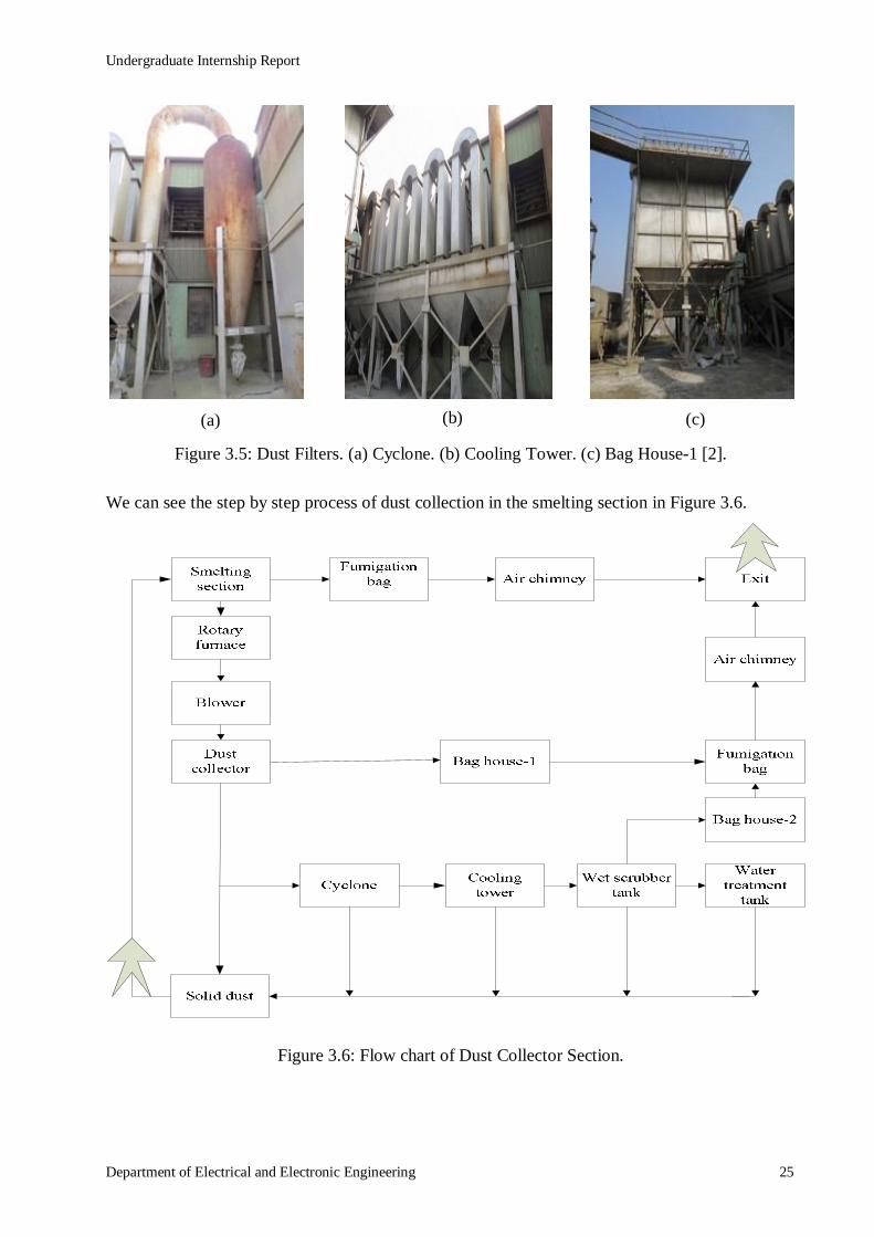
At first all dusts are stored in dust collector through blower. Large size solid dust is stored in dust
collector, then the medium size solid dust is stored in cooling tower by cyclone which are shown
in Figure 3.5 and small size dust is stored in bag house-1.The bag house-1 and bag house-2 suck
the dust, then fresh air blows out through air chimney. All fume dusts are filtered by the
fumigation bag and fresh air blows out through air chimney. All solid dusts are put in the wet
scrubber tank by the motor, then water flows over the dust and weighted materials are stored
under the tank. Then the collected solid dusts are reused in smelting section.
(b) (a)
Undergraduate Internship Report
Department of Electrical and Electronic Engineering 25
Figure 3.5: Dust Filters. (a) Cyclone. (b) Cooling Tower. (c) Bag House-1 [2].
We can see the step by step process of dust collection in the smelting section in Figure 3.6.
Figure 3.6: Flow chart of Dust Collector Section.
(c) (b) (a)
Undergraduate Internship Report
Department of Electrical and Electronic Engineering 26
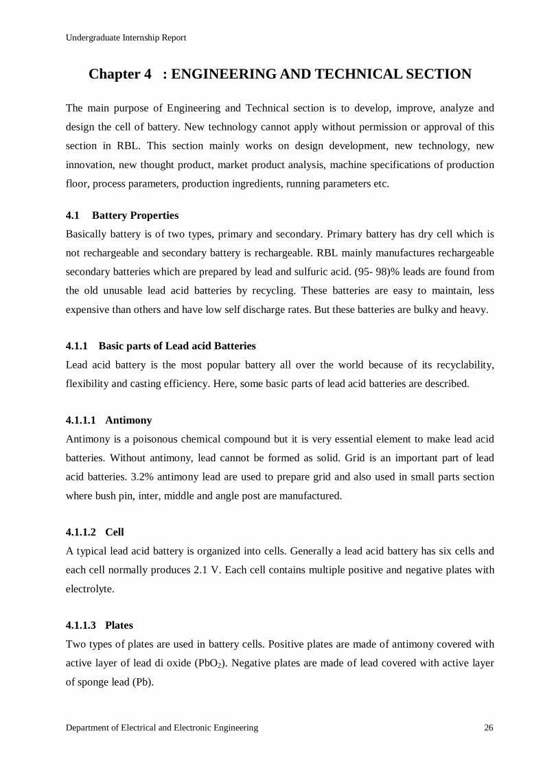
Chapter 4 : ENGINEERING AND TECHNICAL SECTION
The main purpose of Engineering and Technical section is to develop, improve, analyze and
design the cell of battery. New technology cannot apply without permission or approval of this
section in RBL. This section mainly works on design development, new technology, new
innovation, new thought product, market product analysis, machine specifications of production
floor, process parameters, production ingredients, running parameters etc.
4.1 Battery Properties
Basically battery is of two types, primary and secondary. Primary battery has dry cell which is
not rechargeable and secondary battery is rechargeable. RBL mainly manufactures rechargeable
secondary batteries which are prepared by lead and sulfuric acid. (95- 98)% leads are found from
the old unusable lead acid batteries by recycling. These batteries are easy to maintain, less
expensive than others and have low self discharge rates. But these batteries are bulky and heavy.
4.1.1 Basic parts of Lead acid Batteries
Lead acid battery is the most popular battery all over the world because of its recyclability,
flexibility and casting efficiency. Here, some basic parts of lead acid batteries are described.
4.1.1.1 Antimony
Antimony is a poisonous chemical compound but it is very essential element to make lead acid
batteries. Without antimony, lead cannot be formed as solid. Grid is an important part of lead
acid batteries. 3.2% antimony lead are used to prepare grid and also used in small parts section
where bush pin, inter, middle and angle post are manufactured.
4.1.1.2 Cell
A typical lead acid battery is organized into cells. Generally a lead acid battery has six cells and
each cell normally produces 2.1 V. Each cell contains multiple positive and negative plates with
electrolyte.
4.1.1.3 Plates
Two types of plates are used in battery cells. Positive plates are made of antimony covered with
active layer of lead di oxide (PbO2). Negative plates are made of lead covered with active layer
of sponge lead (Pb).

Undergraduate Internship Report
Department of Electrical and Electronic Engineering 27
4.1.1.4 Separators
In a cell, plates are separated by thin insulators. Insulators allow the electrolyte to pass freely
between the plates and it separates the negative and positive plate from touching each other to
remove short circuit.
4.1.1.5 Electrolyte
The electrolyte is a mixture of sulfuric acid (HଶSOସ) and water (H2O). The electrolyte creates
chemical bond with active materials of the grid to generate electrical pressure which produce the
voltage.
4.1.1.6 Battery Case
The battery case holds and protects all of the internal components and also contains the
electrolyte. A container should be sealed and should have the capacity to remove electrolyte
leakage.
4.1.1.7 Vent Cap
Vent cap releases hydrogen gas when the battery charges. Some vent caps are attached with
battery and some are not attached with battery.
4.1.2 Battery Function
The basic functions of a battery are starting, running and turning off engine. Battery provides
energy to operate lights and accessories and to start the engine. It also services as voltage
stabilizer to protect voltage sensitive circuits and particularly digital circuits. It is the main source
of electrical energy in vehicles. Battery powers some major electrical systems which are:
Starting,
Ignition,
Charging,
Lighting and
Accessories.
4.2 Basic Purpose of Grid Design
Engineering and technical section designs the grid based on material property, electrical
conductivity. Then they plot the battery model using MATLAB and then test it electrically. Grid
mesh is designed based on hold active material, conduct current, casting ability and strength.

Undergraduate Internship Report
Department of Electrical and Electronic Engineering 28
4.2.1 Hold Active Material
Hold active material means the grid should have the capacity to hold the pasting materials.
Otherwise the charging and discharging process should not occur properly and the battery could
not store the energy.
4.2.2 Conduct Current
Grids work as a conductor in a cell. To get good conductivity, mesh density is kept high in lug
side because wires are always connected with grid lug and current enters and outs through the
grid. So, radial mesh is more preferable for grid design. It also depends on grid thickness and
active materials. If the thickness of grid is thin and grid has less active material then rectangular
mesh design is more preferable than radial mesh design.
4.2.3 Casting Ability
Melted lead is poured on the mold of grid casting machine. It should be flown uniformly toward
the top to bottom path with same rate. There should have enough places for deposition otherwise
it makes a cold joint. This joint will be opened at first in its service life and current flow will be
stopped. Paths are created to think all about these and entire these things depend on casting
ability of a grid mesh.
4.2.4 Strength
Strength is an important part of grid designing. There are two types of strengths, cycling strength
and operational life strength. A grid that has both types of strengths is considered proper for
designing battery.
4.2.4.1 Cycling Strength
Cycling strength means the grid can perform repeatedly in the same cycle. Charging and
discharging happen in a cycle in service life. As a part of this, heat is produced and the grid is
expanded. When the grid is cooled down, it is contracted. For this reason if this grid does not
have enough strength then the interconnection of the grid will be damaged. This will cause
shorter service life.
4.2.4.2 Operational Life Strength
In operational life, the grid should have the paste holding ability otherwise when the active
material are pasted on the grid, it will not hold the active materials and it could be bent when it

Undergraduate Internship Report
Department of Electrical and Electronic Engineering 29
put on the pasting machine. This strength is called operational life strength. It should have the
hanging capacity otherwise it cannot stay in skid. The grid should have the strength to align
properly otherwise it could not assemble in a cell properly.
4.3 Charging and Discharging Properties of a Battery
The function of lead acid battery is fully based on simple chemical reaction. When two dissimilar
metals are immersed in an acid solution, the electric energy converts into chemical energy and
produced a voltage. Lead acid batteries are charged and discharged based on this simple reaction.
4.3.1 Fully charged
During fully charged position of the battery, positive plates are covered with lead dioxide (PbO2)
and negatives plates are covered with spongy lead (Pb). Electrolyte contains water (H2O) and
sulfuric acid (H2SO4).
4.3.2 Discharging
During discharged position of the battery, current flows in the cell from the negative to the
positive plates. Electrolyte separates into hydrogen (H2) and sulfate (SO4) and the free sulfate
combines with the lead (both lead dioxide and spongy lead) and becomes lead sulfate (PbSO4).
At last the free hydrogen and oxygen combine to form more water for diluting the electrolyte.
4.3.3 Fully Discharged
During fully discharged position of the battery, both plates are fully sulfated and electrolyte is
almost diluted to the water.
4.3.4 Charging
During charged position of the battery, the chemical reaction is reversed that took place during
discharging. Sulfate (SO4) leaves the positive and negative plates and combines with hydrogen
(H2) to become sulfuric acid (H2SO4). Hydrogen bubbles form at the negative plates and oxygen
(O2) appears at the positive plates. Free oxygen (O2) combines with lead (Pb) at the positive plate
to become lead dioxide (PbO2).
4.4 Emf Calculation
The lead acid battery is one of the most common batteries which is used in automobiles. A 12 V
automotive battery consists of six cells which are connected in series. If six cells individually
Undergraduate Internship Report
Department of Electrical and Electronic Engineering 30
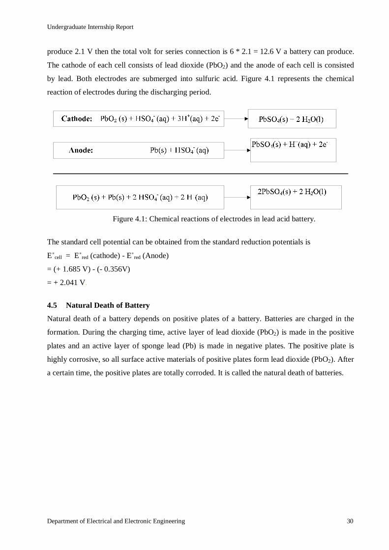
produce 2.1 V then the total volt for series connection is 6 * 2.1 = 12.6 V a battery can produce.
The cathode of each cell consists of lead dioxide (PbO2) and the anode of each cell is consisted
by lead. Both electrodes are submerged into sulfuric acid. Figure 4.1 represents the chemical
reaction of electrodes during the discharging period.
Figure 4.1: Chemical reactions of electrodes in lead acid battery.
The standard cell potential can be obtained from the standard reduction potentials is
E˚cell = E˚red (cathode) - E˚red (Anode)
= (+ 1.685 V) - (- 0.356V)
= + 2.041 V.
4.5 Natural Death of Battery
Natural death of a battery depends on positive plates of a battery. Batteries are charged in the
formation. During the charging time, active layer of lead dioxide (PbO2) is made in the positive
plates and an active layer of sponge lead (Pb) is made in negative plates. The positive plate is
highly corrosive, so all surface active materials of positive plates form lead dioxide (PbO2). After
a certain time, the positive plates are totally corroded. It is called the natural death of batteries.
Undergraduate Internship Report
Department of Electrical and Electronic Engineering 31
Chapter 5 : PLASTIC SECTION
Plastic materials of different types of batteries are manufactured in Plastic Section. According to
customer demand many types of containers and covers are prepared in this section. Labeling and
printing on the containers are also managed in this section according to batteries type and
customer demand. Some plastic instruments like polypropylene, colorful pigment are imported
from foreign countries. Plastic are two types, thermostat plastic and thermosetting plastic.
Thermostat plastics are recyclable, so, battery container, cover and vent plug are prepared by
thermostat plastic. Electrical equipment are prepared by unrecyclable thermosetting plastic.
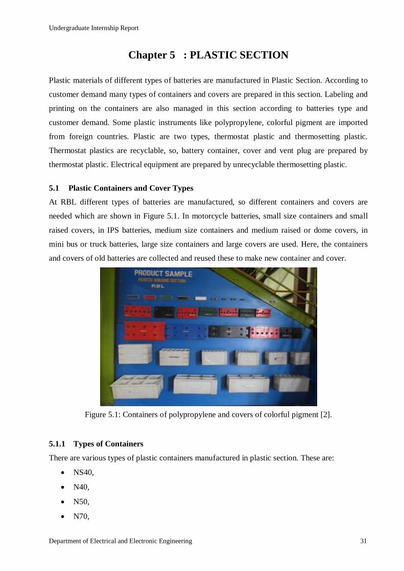
5.1 Plastic Containers and Cover Types
At RBL different types of batteries are manufactured, so different containers and covers are
needed which are shown in Figure 5.1. In motorcycle batteries, small size containers and small
raised covers, in IPS batteries, medium size containers and medium raised or dome covers, in
mini bus or truck batteries, large size containers and large covers are used. Here, the containers
and covers of old batteries are collected and reused these to make new container and cover.
Figure 5.1: Containers of polypropylene and covers of colorful pigment [2].
5.1.1 Types of Containers
There are various types of plastic containers manufactured in plastic section. These are:
NS40,
N40,
N50,
N70,

Undergraduate Internship Report
Department of Electrical and Electronic Engineering 32
6X15,
6XT15,
N100,
N120,
N150,
N200 and
EV 120.
Here, NS40 is smallest type container and N200 is largest type container which are manufactured
in this factory. Others necessary containers and smaller than NS40 or larger than N200 containers
are not manufactured in this factory, those are imported from others countries.
Some containers are imported from other countries which are called DIN type containers. They
are:
DIN 44,
DIN 88,
DIN 45 and
DIN 46.
5.1.2 Types of Covers
Mainly three types of covers are manufactured in this factory such as coin flash, dome and raised
cover. Coin flash and dome cover are made for coin flash vent plug and raised cover is made for
raised vent plug.
5.1.2.1 Coin Flash Cover
This cover is manufactured to set up the coin flash vent plug and it is used in exportable battery.
Coin flash cover is better than raised cover and it is expensive than raised cover batteries.
5.1.2.2 Dome Cover
Dome cover looks like a coin flash cover but its height is small bit larger than coin flash cover. It
is used in different types of car batteries. Coin flash vent plug is used in dome cover.
5.1.2.3 Raised Cover
This type of cover is manufactured to set up the raised vent plug, so this cover is called raised
cover. This type of cover is used in local battery container like IPS, motorcycle battery etc.

Undergraduate Internship Report
Department of Electrical and Electronic Engineering 33
5.2 Uses of Plastic Crusher and Mixture Machine
Old and unusable plastic covers, containers are broken by the different crusher machines.
Containers are broken in the crusher machine-1 which is shown in Figure 5.2(a) and colorful
covers are broken in the crusher machine-2 which is shown in Figure 5.2(b). White
polypropylene and crushed plastic are mixed in the mixture machine which is shown in Figure
5.2(c). In this way unused plastics are reused to prepare new plastic container.
Figure 5.2: Plastic Crusher & Mixture Machines. (a) Crusher Machine-1. (b) Crusher Machine -2. (c) Mixture Machine [2].
5.3 Uses of Parts of Plastic Molding Machine
Using different mold inside the plastic molding machine, different plastic parts of battery is
manufactured here.
5.3.1 Vacuum Suckers
Vacuum sucker sucks plastic raw materials and passes them in the hopper part of the plastic
molding machine which is shown in Figure 5.3. One side of this vacuum sucker is connected
with the hopper and another side is kept on the mixture drum.
Figure 5.3: Vacuum Sucker [2].
5.3.2 Hopper
Hopper is a receiver where all types of plastics are stored and melted for making plastic
instrument for the battery. Plastics are sent here by vacuum suckers and auto loader machine.
Sometimes manually plastics are kept here. Plastic are melted here by heat.
(a) (b) (c)

Undergraduate Internship Report
Department of Electrical and Electronic Engineering 34
5.3.3 Auto Loader Machine
In plastic molding machine plastic raw materials are sent in the hopper by auto loader machine
which is shown in Figure 5.4. There is a regulator which regulates the amount of raw material
that is needed to fill up the hopper. When the hopper is filled up with the plastic raw material, the
auto loader machine automatically shuts down. When the machine needs more raw materials, the
auto loader machine automatically turns on and fills up the hopper according to the requirement.
Figure 5.4: Auto Loader Machine [2].
5.3.4 Cooler Machine
Cooler machine cools the molds and injection unit of the plastic molding machine and also helps
to cool the container, cover and vent plug in the molding machine. Figure 5.5 shows a cooler
machine which is connected with a water tank. This water tank is located outside the plastic
section.
Figure 5.5: Cooler Machine [2].
5.4 Manufacturing Plastic Container and Cover
Plastic container is prepared by polypropylenes. Only 10% recycled polypropylenes (crushed
plastic) are mixed with imported polypropylenes to prepare the plastic container. The container
manufacturing machine is shown in Figure 5.6.

Undergraduate Internship Report
Department of Electrical and Electronic Engineering 35
Figure 5.6: Plastic Cover Molding Machine. (a) Inside of Machine. (b) Outside of Machine [2].
The mold of plastic cover manufacturing machine is different from the mold of container
manufacturing machine. Polypropylenes are mixed with different amount of colorful pigment to
manufacture different color plastic cover. Table 2 shows the amount of polypropylenes and
pigment which are used to prepare the covers of different colors.
Table 2: Amount of polypropylenes and pigments for different colored covers.
Serial No. Cover and Pigment Color Amount of Polypropylenes
(kg)
Amount of pigments
(gm)
1 Red 25 600
2 Blue 25 800
3 Green 25 600
4 Yellow 25 400
5 Bottle Green 25 1000
6 Black 25 400
Only 25% recycled polypropylenes are mixed with imported colorful pigments to prepare the
plastic container cover. The container manufacturing machine and the cover manufacturing
machine mold are not same but the production processes are almost same. Figure 5.7 represents
the flow process of manufacturing plastic containers and covers.
Figure 5.7: Process of Manufacturing Plastic Container and Cover.
(b) (a)
Undergraduate Internship Report
Department of Electrical and Electronic Engineering 36
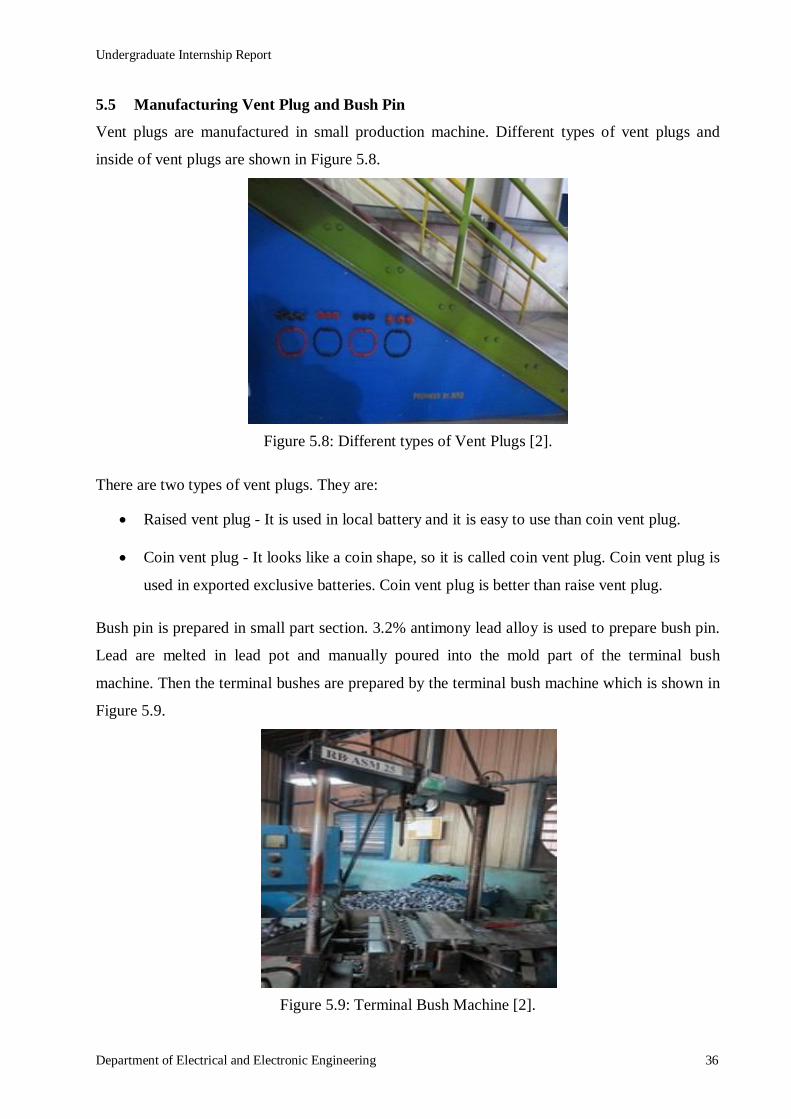
5.5 Manufacturing Vent Plug and Bush Pin
Vent plugs are manufactured in small production machine. Different types of vent plugs and
inside of vent plugs are shown in Figure 5.8.
Figure 5.8: Different types of Vent Plugs [2].
There are two types of vent plugs. They are:
Raised vent plug - It is used in local battery and it is easy to use than coin vent plug.
Coin vent plug - It looks like a coin shape, so it is called coin vent plug. Coin vent plug is
used in exported exclusive batteries. Coin vent plug is better than raise vent plug.
Bush pin is prepared in small part section. 3.2% antimony lead alloy is used to prepare bush pin.
Lead are melted in lead pot and manually poured into the mold part of the terminal bush
machine. Then the terminal bushes are prepared by the terminal bush machine which is shown in
Figure 5.9.
Figure 5.9: Terminal Bush Machine [2].
Undergraduate Internship Report
Department of Electrical and Electronic Engineering 37
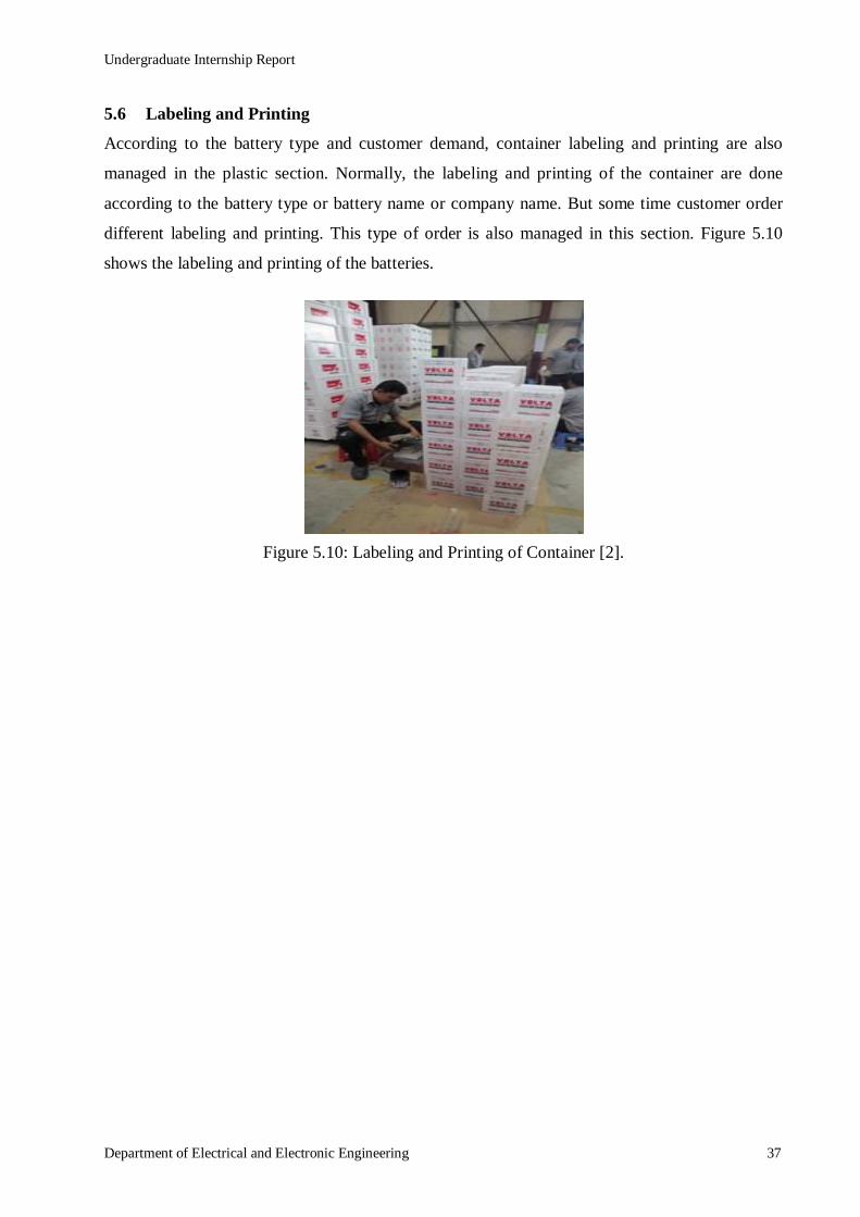
5.6 Labeling and Printing
According to the battery type and customer demand, container labeling and printing are also
managed in the plastic section. Normally, the labeling and printing of the container are done
according to the battery type or battery name or company name. But some time customer order
different labeling and printing. This type of order is also managed in this section. Figure 5.10
shows the labeling and printing of the batteries.
Figure 5.10: Labeling and Printing of Container [2].

Undergraduate Internship Report
Department of Electrical and Electronic Engineering 38
Chapter 6 : PLATE PREPARATION SECTION
The plates of cells are prepared and managed in this section. Plate is the most important part of a
battery. The plate preparation processes is most critical and creative process of RBL. This
process needs many times. Plates are prepared in different steps which are briefly described in
this section.
6.1 Grid casting
Different sizes and types of grids are prepared in grid casting machine. Different quantities of
antimony lead are used to prepare the grid. Grid machine has different parts where lead alloy is
melted first then it is poured in the mold part where grids are formed. Then it is sent to the cutter
to cut the scrap part. Then the final grids come out from the machine by conveyer belt. The grid
casting machine is shown in Figure 6.1.
Figure 6.1: Grid Casting Machine [2].
6.1.1 Parts of Grid Casting Machine
There are different parts of grid casting machine. The working process of some parts of the grid
casting machine are explained here.
6.1.1.1 Lead Pot
Lead pot is used to melt the lead where certain temperature is needed to melt the lead. Here, (455-
480)˚C temperature is needed which is generated by gas burner or electric heater. A lead pump is
used to transfer the liquid lead to the ladle through feed line and dispense valve.
6.1.1.2 Feed Line
It is a cylindrical shaped supply line which is used to transfer the melted lead to the dispense
valve. Here, 4000 watt, 3000 watt and 1500 watt electrical heaters are used to heat the feed line to
keep the temperature at a desired level and to prevent the liquid lead from turning into solid.

Undergraduate Internship Report
Department of Electrical and Electronic Engineering 39
6.1.1.3 Lead Dispense Valve
It is used to ensure the accurate distribution of melted lead from feed line to ladle.
6.1.1.4 Ladle Part
Ladle pours certain amount of melted lead to the mold. In ladle, there are a gas burner and a
heater to maintain certain temperature which is monitored on a display board.
6.1.1.5 Mold Part
The main function of the mold is to form a solid grid from melted lead. This mold part has two parts,
namely fixed part and movable part. Both parts have individually two heaters to maintain the even
temperature in the mold. The movement of the mold is controlled by the limit switch, solenoid
valve. There are some pins in fixed mold to detach the grid after preparing the grid.
6.1.1.6 Grid Transport
The formed grids are sent to the transfer rulers through transfer belt. Then the grid is transferred
to the cutter to cut the unexpected part or scrap part. Then the scrap part is sent to the lead pot by
conveyer belt and prepared grid is come out by another conveyer belt.
6.2 Lead Oxide Preparation
99.97% pure lead is used to manufacture lead oxide. Following steps are done for lead oxide
preparation.
In cylinder casting machine melted leads are formed in cylindrical shapes where diameter
of the cylinder is 18 millimeter and length is 18 to 22 millimeter. Cylinder casting
machine is shown in Figure 6.2(a).
Figure 6.2: Lead Oxide Preparation. (a) Cylinder Casting Machine. (b) Lead Oxide Mill [2].
Small shape cylinders are stored in the silo through elevator bucket. These cylinders need
16 hours to get cooled. Silo is shown in Figure 6.2(b).
(b) (a)
Undergraduate Internship Report
Department of Electrical and Electronic Engineering 40
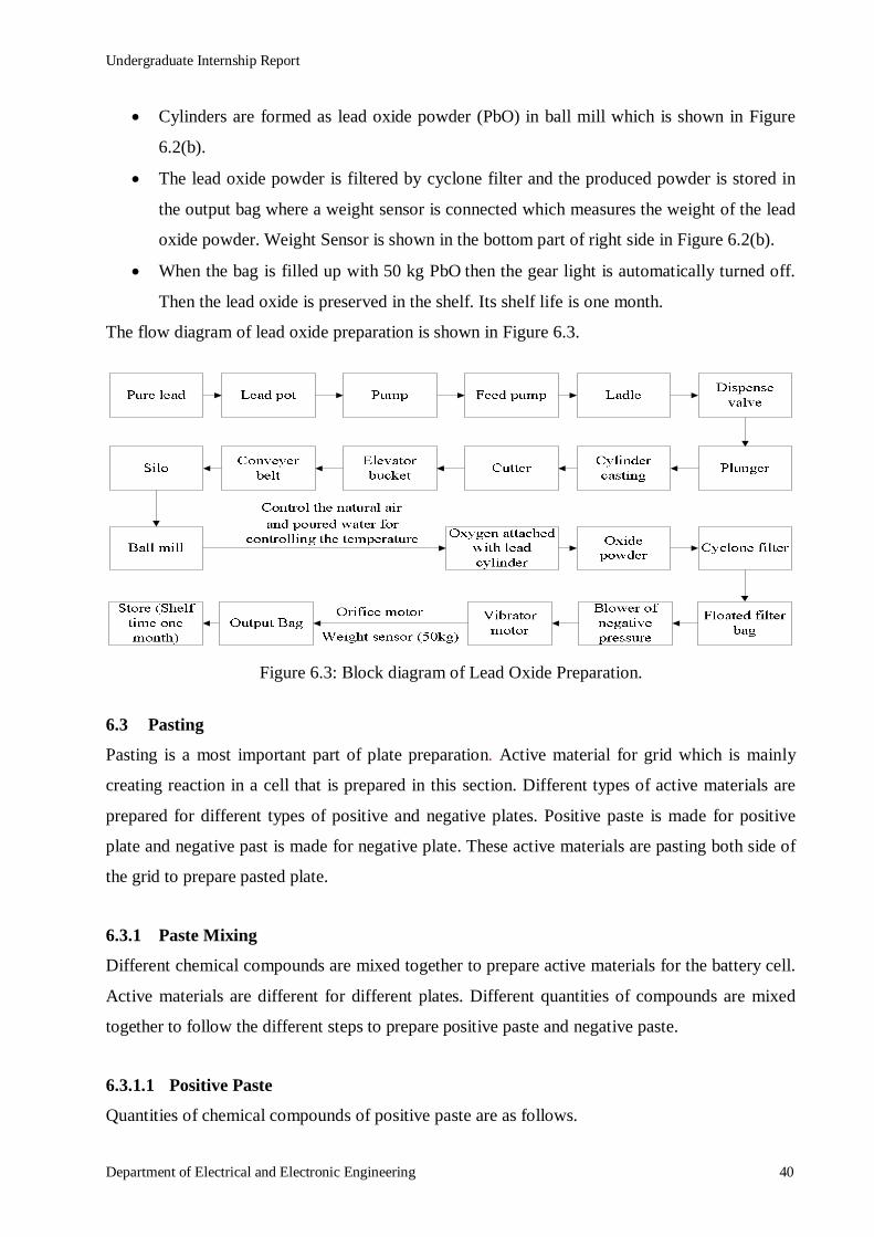
Cylinders are formed as lead oxide powder (PbO) in ball mill which is shown in Figure
6.2(b).
The lead oxide powder is filtered by cyclone filter and the produced powder is stored in
the output bag where a weight sensor is connected which measures the weight of the lead
oxide powder. Weight Sensor is shown in the bottom part of right side in Figure 6.2(b).
When the bag is filled up with 50 kg PbO then the gear light is automatically turned off.
Then the lead oxide is preserved in the shelf. Its shelf life is one month.
The flow diagram of lead oxide preparation is shown in Figure 6.3.
Figure 6.3: Block diagram of Lead Oxide Preparation.
6.3 Pasting
Pasting is a most important part of plate preparation. Active material for grid which is mainly
creating reaction in a cell that is prepared in this section. Different types of active materials are
prepared for different types of positive and negative plates. Positive paste is made for positive
plate and negative past is made for negative plate. These active materials are pasting both side of
the grid to prepare pasted plate.
6.3.1 Paste Mixing
Different chemical compounds are mixed together to prepare active materials for the battery cell.
Active materials are different for different plates. Different quantities of compounds are mixed
together to follow the different steps to prepare positive paste and negative paste.
6.3.1.1 Positive Paste
Quantities of chemical compounds of positive paste are as follows.

Undergraduate Internship Report
Department of Electrical and Electronic Engineering 41
Lead oxide (PbO): 600 kg.
Sulfuric acid (H2SO4): 45±1 liters (Gravity of acid: 1.400, 30˚C).
De mineralized water (DM water): 78±3 liters.
Fiber flock: 360 gm.
6.3.1.2 Negative Paste
Quantities of chemical compound for negative paste are as follows.
Lead oxide (PbO): 600 kg.
Fiber flock: 360gm.
DM water: 72-75 liters.
Sulfuric acid (H2SO4): 42±1 liters (Gravity of acid: 1.400, 30˚C).
Indulin C: 1200 gm.
Carbon black: 1800 gm.
Barium Sulfate: 2400 gm.
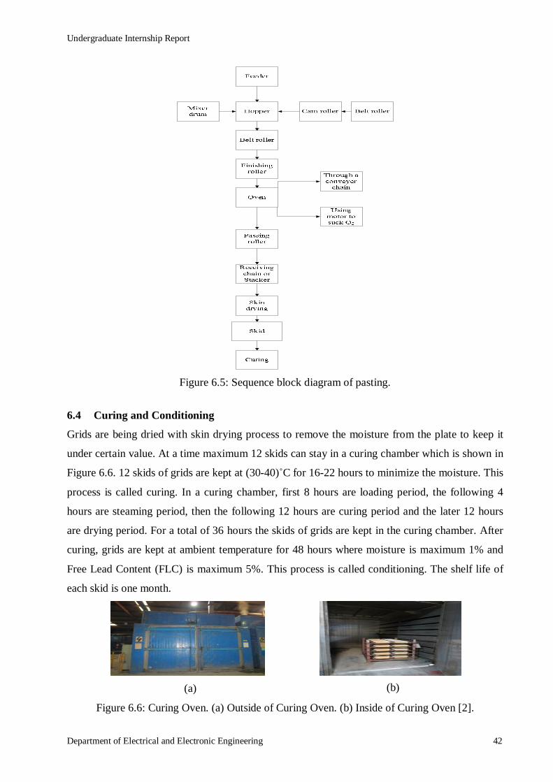
6.3.2 Pasting Process
At first pastes are manually poured in the hopper from mixture dram. On the other side, 50
bunches of grids are put in the belt roller which sends the grids into the cam roller or auto lifter.
When the pasting machine is turned on, then the pastes are pasting on the grid by a roller and the
pasting is finished in the finishing roller which is shown in Figure 6.4.
Figure 6.4: Pasting Machine [2].
Then the pasted plates are passed into the oven by conveyer chain. Then it is sent into the
receiving chain by passing roller and the pasted plates are put in the skid. The skid has five layers
and has a square shape tray in the bottom which is filled up by water. The five layers of skid are
covered by the wet jute bag. These wet jute bags and water filled tray are used to keep the
accurate moisture, otherwise these pasted plates will create reaction with air and will lose the
moisture range. Then the skid is sent to the curing oven. The sequence block diagram of pasting
process is shown in Figure 6.5.
Undergraduate Internship Report
Department of Electrical and Electronic Engineering 42
Figure 6.5: Sequence block diagram of pasting.
6.4 Curing and Conditioning
Grids are being dried with skin drying process to remove the moisture from the plate to keep it
under certain value. At a time maximum 12 skids can stay in a curing chamber which is shown in
Figure 6.6. 12 skids of grids are kept at (30-40)˚C for 16-22 hours to minimize the moisture. This
process is called curing. In a curing chamber, first 8 hours are loading period, the following 4
hours are steaming period, then the following 12 hours are curing period and the later 12 hours
are drying period. For a total of 36 hours the skids of grids are kept in the curing chamber. After
curing, grids are kept at ambient temperature for 48 hours where moisture is maximum 1% and
Free Lead Content (FLC) is maximum 5%. This process is called conditioning. The shelf life of
each skid is one month.
Figure 6.6: Curing Oven. (a) Outside of Curing Oven. (b) Inside of Curing Oven [2].
(b) (a)

Undergraduate Internship Report
Department of Electrical and Electronic Engineering 43
6.5 Formation
After curing and conditioning, formation process is done for charging both the positive and negative
plates. Here, plates are dipped into the sulfuric acid mixer and the plates are charged using
rectifier. This process continues up to 18-22 hours. De-Mineralized (DM) water is also managed in
this section.
6.5.1 DM Water Plant
In the time of paste mixing and formation, mineral mixed water is created problem to form
appropriate bond. For this reason, RBL made a DM plant to fulfill its own demand. Natural water
is de-mineralized in DM plant which is shown in Figure 6.7. In this plant, mineral compound as
like calcium, chloride, arsenic, nickel, iron, cyanide, nitride etc. are removed from water.
Figure 6.7: DM Water Plant [2].
6.5.2 Plate Charging
Plates are charged in a vat and all plates are aligned in this vat furnace. Following steps are done
for plate charging.
Positive plates and negative plates are put together in this circuit furnace which is shown
in Figure 6.8(a).
Plates are dipped into the sulfuric acid (gravity 1.05 - 1.06) mixed water.
Plates are charged using rectifier. The lugs of positive plates are put in series connection
with the positive cable of rectifier and the negative plates are put in series connection
with negative cable of this rectifier.
Figure 6.8: Formation of Pasted Plates. (a) Charging Plates in Vat. (b) Scrubber [2]. (a) (b)
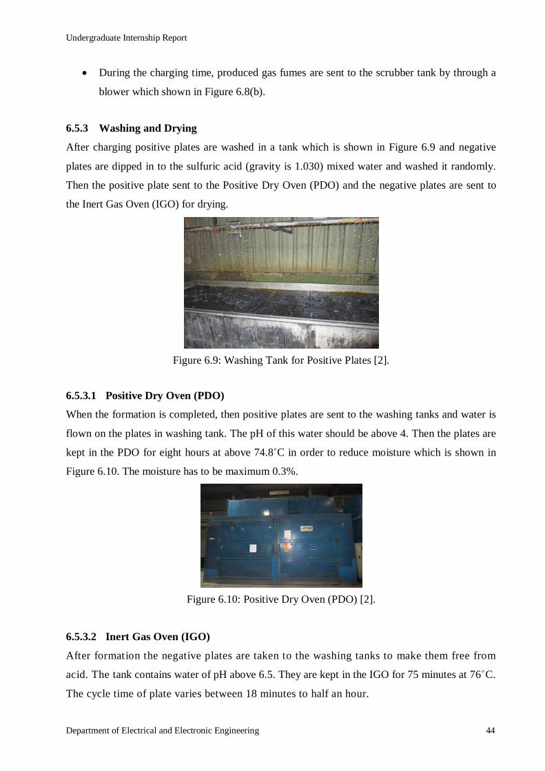
Undergraduate Internship Report
Department of Electrical and Electronic Engineering 44
During the charging time, produced gas fumes are sent to the scrubber tank by through a
blower which shown in Figure 6.8(b).
6.5.3 Washing and Drying
After charging positive plates are washed in a tank which is shown in Figure 6.9 and negative
plates are dipped in to the sulfuric acid (gravity is 1.030) mixed water and washed it randomly.
Then the positive plate sent to the Positive Dry Oven (PDO) and the negative plates are sent to
the Inert Gas Oven (IGO) for drying.
Figure 6.9: Washing Tank for Positive Plates [2].
6.5.3.1 Positive Dry Oven (PDO)
When the formation is completed, then positive plates are sent to the washing tanks and water is
flown on the plates in washing tank. The pH of this water should be above 4. Then the plates are
kept in the PDO for eight hours at above 74.8˚C in order to reduce moisture which is shown in
Figure 6.10. The moisture has to be maximum 0.3%.
Figure 6.10: Positive Dry Oven (PDO) [2].
6.5.3.2 Inert Gas Oven (IGO)
After formation the negative plates are taken to the washing tanks to make them free from
acid. The tank contains water of pH above 6.5. They are kept in the IGO for 75 minutes at 76˚C.
The cycle time of plate varies between 18 minutes to half an hour.

Undergraduate Internship Report
Department of Electrical and Electronic Engineering 45
6.6 Plate Parting
After drying, each charged plate is parted into two parts by plate parting machine. When grids are
pasted and charged, then the grid lug becomes oily and dusty. So, the lugs are also cleaned by
wheel brush in this machine. Figure 6.11 shows the sequence block diagram of plate parting.
Figure 6.11: Sequence block diagram of plate parting.

Undergraduate Internship Report
Department of Electrical and Electronic Engineering 46
Chapter 7 : ASSEMBLY SECTION
In the assembly section, finally the components of batteries are assembled. Assembly section
uses the pasted plates to assemble the battery. After assembling, we can use the batteries after
filling electrolyte. The raw materials of assembling batteries are plate, separator, cover,
container, small parts and accessories.
7.1 Small Parts of Battery
The small parts are casted in small parts casting section which is controlled by assembly section.
In small parts casting section 3.2% antimony lead is used. There are four types of small parts like
as ring post, main post, inter middle post, inter post, angle post and lead stick. Lead stick is
shown in Figure 7.1(a). Here, the names of different types of posts are given.
7.1.1 Ring Post
Ring post is also called screw post. It is used in large size battery. Figure 7.1(b) shows the mold
of ring post. The names of different types of ring posts are as follows.
N100,
N120,
N150 and
N200.
Figure 7.1: Lead Stick and Ring Post Preparing Mold. (a) Lead Pot with Lead Stick. (b) Ring Post Mold [2].
7.1.2 Main Post
Main posts are used in terminal bush burning in assembly section. The names of different types
of main posts are:
N70,
(a) (b)
Undergraduate Internship Report
Department of Electrical and Electronic Engineering 47
N50,
NS40,
NS60,
N100,
N120,
N200,
DIN88 and
DIN55.
7.1.3 Inter Middle Post
Inter middle posts and inter posts are used in group burning in assembly section. The names of
different types of inter middle posts are:
N120,
N150 and
N200.
7.1.4 Angle Post
Angle posts are also used in group burning. Names of different types of angle posts are:
NS40 (Left and Right),
N40 (Left and Right),
NS60 (Left and Right) and
N50 (Left and Right).
7.2 Process of Assembly Section
There are thirteen steps of assembling a battery. After completing this process, batteries are
completely assembled. The steps of assembling battery are described here.
7.2.1 Envelope Cutting
There is a P-envelope machine in assembly section where the roll of Polyethylene (PE) separator
is attached which is shown in Figure 7.2 and it cuts the PE separator in envelope size. One side of
PE separator is rib side and another side is plane side. There are two types of separators, one is
HN 1.2 (2 mm) and another is HN 1.2 (4 mm). After cutting, envelopes are sent to the separating
portion.

Undergraduate Internship Report
Department of Electrical and Electronic Engineering 48
Figure 7.2: PE Separator Cutting Machine [2].
7.2.2 Separating
Creating a group with PE separator envelope, positive and negative pasted plate, that process is
called separating which is shown in Figure 7.3. This group is created according to coupling. In
some batteries, positive plates remain in separator envelope.
Figure 7.3: Positive and Negative Separated Plates [2].
7.2.3 Group Burning
After separating, the flags of positive plates are joined and the negative plates are also joined by
melting lead stick with the help of oxyacetylene gas torch which is shown in Figure 7.4. At the
same time the main posts, inter middle posts and angle posts (left and right) are also joined by the
melted lead. It is called group burning.
Figure 7.4: Group Burning with Lead Stick [2].
7.2.4 Indicating Positive Plate
After group burning only the positive plates are indicated by color. So, everyone can identify the
positive and negative plates. Figure 7.5 represents the indicated positive plates.

Undergraduate Internship Report
Department of Electrical and Electronic Engineering 49
Figure 7.5: Indicated Positive Plates [2].
7.2.5 Cell Insert
After indicating the positive plates, the joints of positive plates and the joints of negative plates
are checked properly. Then the cells are inserted into the plastic container which is shown in
Figure 7.6.
Figure 7.6: Inserted Cell [2].
7.2.6 Short and Polarity Test
In the plastic container, a group of positive plates remain beside a group of negative plates. Here,
the arrangements of cells are checked properly and manually polarity is checked. Then two
probes of short testing machine are used for short testing. One probe is held in positive side and
another probe is held in negative side. If any how the positive and negative plates are shorted
then the alarm will ring otherwise alarm will not ring.
7.2.7 Inter Cell Welding
In inter cell welding, here is done resistance spot welding by inter cell welding machine which is
shown in Figure 7.7. There are hole punches in the partitions of plastic containers. At the time of
inter cell welding two inter posts are set in the two sides of hole. The high current is passed
through the inter cell welding tips. When the electrons flow through the tips, they get air
resistance and then temperature is generated there. The inter cell welding tips hold the inter posts
with pressure, so the lead is melted and an inter post is joined with other. Then after a few time it
will be solid.

Undergraduate Internship Report
Department of Electrical and Electronic Engineering 50
Figure 7.7: Inter Cell Welding Machine [2].
7.2.8 Shear Testing
In shear testing, the joint of inter cell welding are tested. Here, strong force is applied to the joint
of inter cell welding. If the joint is weak, then the joint will be separated.
7.2.9 Automatic Heat Sealing
In the automatic heat sealing machine, the lower part of plastic cover and the upper part of plastic
container are melted to attach with one another. This automatic heat sealing machine takes
around two hours to set. Figure 7.8 shows the automatic heat sealing machine.
Figure 7.8: Automatic Heat Sealing Machine [2].
7.2.10 Pole Burning with Terminal Bush
There are two main posts or poles in the battery. For pole burning, a burning guard is kept on the
ring post and ring post is kept on the terminal bush and then the pole is burnt by melting lead
stick with the help of oxyacetylene gas torch which is shown in Figure 7.9. The positive and
negative electrical connections are connected to these two poles of the battery.

Undergraduate Internship Report
Department of Electrical and Electronic Engineering 51
Figure 7.9: Pole Burning with Terminal Post [2].
7.2.11 Leak Testing Machine
By leak testing machine, a positive air is fitted to the six cells of the battery and then pressure
builds up for five to six seconds. If the pressure leaks or drops more than a certain level in a
certain time, then the alarm will ring. If the battery is leaked, then air tight tested device is used.
This leak testing process is also applied to the two adjacent cells, so that internal leakage of a
battery can also be identified. If the battery has no leakage, then pass sticker is tagged on the
battery container.
7.2.12 Aluminum Foiling and Numbering
For aluminum foiling and numbering on the container, two different machines are used which are
shown in Figure 7.10. At first the aluminum foiling is done on the holes of pass sticker holder
battery. Then a permanent numbering process is done on the cover of battery.
Figure 7.10: Aluminum Foiling and Numbering [2].
7.2.13 Shrink Wrapping and Packing
Shrink wrapping and packing is the last step of assembly section process. In the shrink wrapping
and packing process, the battery is wrapped by a shrink paper and some batteries are kept in
carton with vent plug and necessary accessories. At first battery is wrapped by shrink paper, and
then it is passed through a conveyor belt into a covered high temperature zone. So, the shrink
paper is tightly attached to the body of battery. Here, bar codes of the batteries are also scanned.

Undergraduate Internship Report
Department of Electrical and Electronic Engineering 52
7.3 Per Hour Production Capacity
We have observed the per hour production capacity of NS60L battery excluding the leisure time
of workers and the setup time of the machines. Table 3 represents the capacity of separating,
group burning, inter cell welding, heat sealing, pole burning and packing within per hour, 6.5
hours, 7 hours and 8 hours.
Table 3: Production capacity of NS60L battery.
Section Per Hour 6.5 Hours 7 Hours 8 Hours
Separating 40 260 280 320
Group Burning 40 260 280 320
Inter Cell Welding 160 1040 1120 1280
Heat Sealing 180 1170 1260 1440
Pole Burning 300 1950 2100 2400
Packing 192 1248 1344 1536
7.4 Air Treatment Plant
In Air Treatment Plant (ATP), full of lead dust air and fume are filtered. There are two types of
blower. One is air blower and another is fume blower. There is also a filter bag house to collect
the dust from air. Here, the functions of different parts of ATP are described.
7.4.1 Air Blower
The air blower sucks the lead dust mixed air from group burning section. Then the air passes to
the filter bag house to filter the lead dust. Figure 7.11 shows the air blower, fume blower, filter
bag house and dust filter.
Figure 7.11: Air blower, Fume blower, Filter Bag house and Dust Filter [2].

Undergraduate Internship Report
Department of Electrical and Electronic Engineering 53
7.4.2 Fume Blower
The fume blower sucks the fume of polypropylene which is produced in heat sealing section.
Then the fume blows out to the environment. The fume of propylene is not so harmful for
environment so that there is no filter in fume blower.
7.4.3 Filter Bag House
In filter bag house, there are 144 filter bags which are hanging vertically in filter bag house. The
doors of filter bag house are air tight. After sucking the air by air blower, air passes through the
filter bags. Then the lead dust remains in dust collector of filter bags and lead dust free air passes
to dust filter. For cleaning filter bags, after a certain time air is given to the upper side for 1-1.5
seconds.
7.4.4 Dust Filter
The dust filter also filters the air. Sometimes a few dust remains in that air which comes from
filter bag house. Then dust filter filters that air again.
7.4.5 Air Blower with Chimney
After filtering the air completely, this air blower sucks the lead dust free air and blows out the air
through chimney to the environment. If the lead dust remains in air, then after passing a certain
level the lead dust cannot blow out with air through chimney to the environment. Figure 7.12
shows the chimney of ATP.
Figure 7.12: Chimney [2].

Undergraduate Internship Report
Department of Electrical and Electronic Engineering 54
Chapter 8 : QUALITY ASSURANCE DEPARTMENT
Quality Assurance (QA) department is an independent department of RBL. This department is
not included under supply chain. QA department of RBL reports to the General Manager (GM)
of Research and Development (R and D) department in head office and also to the Chief
Executive Officer (CEO) about the quality of product.
8.1 Functions of QA Department
The functions of QA department are as follows.
Checking and controlling quality in every stage as –
o Incoming material,
o In process and
o Finished product.
Holding the product by raising NCPR, which products are failed to meet the standard,
Passing the incoming material,
Collecting the standard sample,
Conducting different test of material or, product,
Providing Batch Number of material or, product and
Accepting and passing daily activity note.
8.2 Testing of Incoming Material and In Process Material
When incoming materials of battery come to the store of RBL after purchasing, then QA
department brings a sample of that material and tests it according to the manual. If the result of
test is perfect, then those materials can come to the production floor. QA department also tests
the in-process materials of all sections with a sample base test.
8.2.1 Smelting Section
QA department tests the melted lead of the smelting section and identifies the quantity of pure
lead and antimony lead. RBL follows OES test process to identify the quantity of lead.
8.2.1.1 OES Test
OES test means Optical Emission Spectrophotometer test. This test is conducted by OES
machine which is controlled by computer. After taking the sample of melted lead, it is serviced
by lead machine. Then after putting the sample into OES machine, a spark is created by electrode

Undergraduate Internship Report
Department of Electrical and Electronic Engineering 55
to send the sample into inside the machine. OES machine identifies the different molecules of
melted lead for their different wavelengths. Then we can see the report in computer. This test is
done by taking two samples.
8.2.2 Plate Preparation Section
QA department tests different materials of plate preparation sections in different process.
8.2.2.1 Grid Test
QA department takes 5 pieces of grids as sample after every four hours (two times per shift) and
tests some properties of grid. This department checks the weight of grid, identifies the crack of
grid, checks the feather and identifies the missing part of grid etc. If the qualities of samples are
good all the grids of these four hours will be passed otherwise, all the grids will be recycled.
8.2.2.2 Lead Oxide Test
QA department takes sample of lead oxide powder after every two hours. Then the apparent
density, mesh size and quantity of Free Lead Content (FLC should be around 28%) are tested
according to the procedure manual. For lead oxide, titration test is used.
8.2.2.3 Pasted Plate Test After Pasting
After every hour, 5 pieces of pasted plates are checked. If the qualities of pastes are good and
pastes are attached properly with the grid, then the pasted plates will pass.
8.2.2.4 Pasted Plate Test After Curing
In curing chamber, the temperature of automotive plate is 60˚C and humidity of automotive plate
is 80%. After completing 36 hours curing time, FLC and moisture of pasted plates are tested in a
sample base. FLC can be maximum 3% and moisture should be less than 1%.
8.2.3 Formation Section
In formation section, the voltages of positive plate and negative plate are measured in the vat
under electrolyte by cadmium test.
8.2.3.1 Cadmium Test
Cadmium test is done by a cadmium metal stick. At first the negative probe of voltmeter
connects to the cadmium metal stick, and then the cadmium metal stick is kept in the electrolyte

Undergraduate Internship Report
Department of Electrical and Electronic Engineering 56
of vat. Then when positive probe touches the positive plate, the voltage of positive plate is shown
in voltmeter. Again when the positive probe touches the negative plate, the voltage of negative
plate is shown in voltmeter. The voltage of positive plate should be around 2.4 V, the voltage of
negative plate should be around 0.2 V and the voltage between positive and negative plate should
be around 2 V.
8.2.3.2 Charged Plate Test After Washing and Drying
After washing the positive plate, percentage of lead die oxide in positive plate is tested. The
range of lead die oxide in positive plate is around 87% - 95%. After drying the negative plates in
Inert Gas Oven (IGO), percentage of lead oxide is tested. The range of lead oxide should be
below 3%.
8.2.4 Assembly Section
QA department tests the small parts and also performs different tests in assembly section.
8.2.4.1 Destructive Test
The test of small parts is called destructive test. Here, a small part is kept in a gas burner for a
few minutes and its inside is checked by breaking. If there is no empty space, the small part is
perfect.
8.2.4.2 Short and Polarity test
In assembly section, QA department performs short and polarity test of a battery per hour. The
arrangement of polarities of battery is manually checked and any short connection between
positive and negative plate is also tested here.
8.2.4.3 Shear Test and Leak Test
In assembly section, QA department also performs shear test and leak test of a battery per hour.
The joint of inter cell welding are tested by shear test. The internal leakage of each battery cell
and the leakage of battery container can be identified by doing leak test.
8.3 Finished Battery Testing
QA department also tests finished battery in a sample base. For some faulty results of finished
battery, finished products of this batch will not hold or reject but QA department will inform it to
Engineering and Technical department. Here, different tests of finished battery are described.
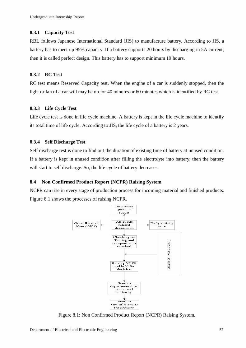
Undergraduate Internship Report
Department of Electrical and Electronic Engineering 57
8.3.1 Capacity Test
RBL follows Japanese International Standard (JIS) to manufacture battery. According to JIS, a
battery has to meet up 95% capacity. If a battery supports 20 hours by discharging in 5A current,
then it is called perfect design. This battery has to support minimum 19 hours.
8.3.2 RC Test
RC test means Reserved Capacity test. When the engine of a car is suddenly stopped, then the
light or fan of a car will may be on for 40 minutes or 60 minutes which is identified by RC test.
8.3.3 Life Cycle Test
Life cycle test is done in life cycle machine. A battery is kept in the life cycle machine to identify
its total time of life cycle. According to JIS, the life cycle of a battery is 2 years.
8.3.4 Self Discharge Test
Self discharge test is done to find out the duration of existing time of battery at unused condition.
If a battery is kept in unused condition after filling the electrolyte into battery, then the battery
will start to self discharge. So, the life cycle of battery decreases.
8.4 Non Confirmed Product Report (NCPR) Raising System
NCPR can rise in every stage of production process for incoming material and finished products.
Figure 8.1 shows the processes of raising NCPR.
Figure 8.1: Non Confirmed Product Report (NCPR) Raising System.

Undergraduate Internship Report
Department of Electrical and Electronic Engineering 58
Chapter 9 : MAINTENANCE SECTION OF RBL
At RBL maintenance section maintains and solves all the problems of machines. Beside this, it
also maintains the generator section and utility section (air distribution and oxygen generation).
This department has six electrical and mechanical engineers and also 33 skilled, semi skilled
technicians or helping hands.
9.1 Categories of Maintenance
The work of maintenance is done in three categories. They are discussed in the following
sections.
9.1.1 Breakdown Maintenance
When a machine breaks down suddenly during the time of running operation, then a team of
maintenance section maintains this type of break down problem, it is called breakdown
maintenance. This type of break down can occur at any time in any machine.
9.1.2 Preventive Maintenance
Preventive maintenance is done to keep the machines in their ideal position. On the basis of the
breakdown history of the last six months, maintenance section creates a check list on some topic
which are also collected from break down history. Then the maintenance section makes a
schedule in the beginning of the month to maintain or calibrate machines and this schedule is also
sent to the planning department and to the user section of machines. This preventive maintenance
is done in following categories.
Weekly,
Monthly,
Quarterly,
Half yearly and
Yearly.
9.1.3 Conditional Maintenance
Conditional maintenance is done on the basis of duration which is given by equipment
manufacturer. The time of this maintenance is given in an Enterprise Resource Planning (ERP)
software, which is called System Applications and Products in Data Processing (SAP). But it is
rarely used.

Undergraduate Internship Report
Department of Electrical and Electronic Engineering 59
9.2 Types and Capacity of Generators
The total load of RBL is around 3 MW but the Rural Electrification Board (REB) supplies only
500 KVA or 400 kW. So, RBL needs generators to fill up their load demand. RBL has five
generators of different capacities.
One diesel generator - 1204 kW,
One diesel generator - 904 kW,
One rental diesel generator - 500 kW,
One gas generator - 1000 kW and
Another gas generator - 1000 kW.
9.3 Substation of REB
REB supplies only 400 kW power to RBL. It is not sufficient for them. Thus at RBL there is a
small substation of REB. There is some equipment in the substation. The equipment are listed in
the following sections. As they did not discuss about the equipment in details, we are only listing
them along with photographs taken by us.
9.3.1 High tension panel
There is one high tension panel in substation for 11 kV voltages which is shown in Figure 9.1.
Figure 9.1: High Tension Panel [2].
9.3.2 Transformer
Figure 9.2 shows a step down transformer which is connected to high tension panel.

Undergraduate Internship Report
Department of Electrical and Electronic Engineering 60
Figure 9.2: Step down Transformer [2].
9.3.3 Change Over Switch (COS)
There is a Change Over Switch (COS) which is used to manually change the source of power
from REB to generator. Figure 9.3 shows the COS used at RBL.
Figure 9.3: Change Over Switch (COS) [2].
9.3.4 Molded Case Circuit Breaker (MCCB)
MCCB means Molded Case Circuit Breaker which is shown in Figure 9.4. By MCCB, current
can be adjusted 160 A to 400 A. When the current rating is larger than 60 A, then MCCB is used.
In the distribution board of home, we use Miniature Circuit Breaker (MCB).
Figure 9.4: MCCB [2].

Undergraduate Internship Report
Department of Electrical and Electronic Engineering 61
9.3.5 Automatic Transfer Switch (ATS)
ATS is also one kind of Change Over Switch (COS) but ATS operates automatically. When the
load is higher than the supply of REB, ATS changes its source automatically. In REB substation,
ATS has two sources and one output which are shown in Figure 9.5.
Figure 9.5: ATS [2].
9.3.6 Capacitor bank
Figure 9.6 represents a capacitor bank in the substation of REB which is used to improve the
power factor. Power factor is considered good when it is 0.9 but it can range from 0.75 to 0.9.
Figure 9.6: Capacitor Bank [2].
9.3.7 Low Tension Panel
There are four low tension panels in substation for 400 V voltages which are shown in Figure
9.7.
Figure 9.7: Low Tension Panel [2].

Undergraduate Internship Report
Department of Electrical and Electronic Engineering 62
9.4 Load Distribution of RBL
The power generated in gas power plant is distributed among different units according to their
required load. Table 4 represents the list of loads for different machines and units.
Table 4: Load Distribution.
Serial No. Name of Machine Rated Power
1
Grid Casting Machine
Wirtz 18.5 kW
Yuasa 33 kW
Diam 11 kW
2 Oxide Mill 80 kW
3 Paste Mixer 4.15 kW
4 Pasting 13 kW
5 Curing Chamber 4 kW
6 Formation (Per Circuit) 25 kW
7 Positive Dry Oven (PDO) 20.2 kW
8 Inert Gas Oven (IGO) 5.96 kW
9 Plate Parting 23.15 kW
10 Assembly 92.11 kW
11 Plastic Molding 50 kW
12 Maintenance 35.1 kW
13 Utility 31.4 kW
14 Oxygen Generator 30 kW
15 Compressor 49 kW
16 Water Pump 15 kW
9.5 Utility section
Utility section is also a part of maintenance section. In utility section, natural air is absorbed and
also filtered, and then the air is delivered to the desired machine. In this section, oxygen gas is
separated from air and delivered to the desired machine.
9.5.1 Process of Natural air Absorbing and Filtering
Natural air is absorbed and filtered to deliver the air to the desired machine. To absorb and filter
the air, following two equipment are used.

Undergraduate Internship Report
Department of Electrical and Electronic Engineering 63
9.5.1.1 Air Compressor
Air compressor sucks the air from the environment, and then it passes to the air preserver to
reserve the air for certain time. Air compressor sucks 10 bar (1 bar = 14.5 pounds per square
inch) air at a time. Figure 9.8 shows the air compressor.
Figure 9.8: Air Compressor [2].
9.5.1.2 Air Dryer
From air preserver, air comes to the air dryer to filter the air dust and remove the moisture. To
remove the air dust and air moisture, two micron filters are used which are shown in Figure 9.9.
Air dust filter - Holds the solid dust and passes the air.
Air moisture dryer - Separates the moisture or water from air.
Figure 9.9: Two Air Dryer Micron Filter [2].
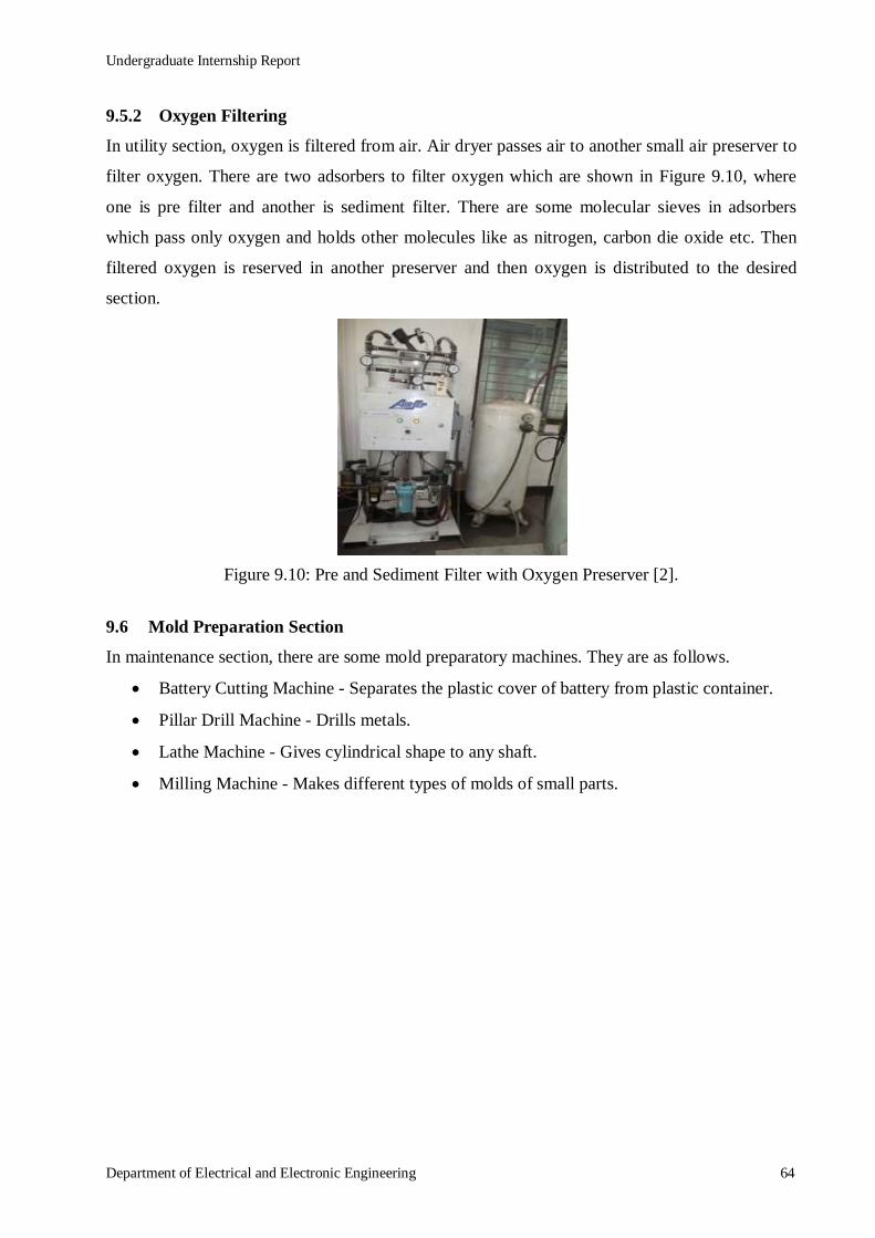
Undergraduate Internship Report
Department of Electrical and Electronic Engineering 64
9.5.2 Oxygen Filtering
In utility section, oxygen is filtered from air. Air dryer passes air to another small air preserver to
filter oxygen. There are two adsorbers to filter oxygen which are shown in Figure 9.10, where
one is pre filter and another is sediment filter. There are some molecular sieves in adsorbers
which pass only oxygen and holds other molecules like as nitrogen, carbon die oxide etc. Then
filtered oxygen is reserved in another preserver and then oxygen is distributed to the desired
section.
Figure 9.10: Pre and Sediment Filter with Oxygen Preserver [2].
9.6 Mold Preparation Section
In maintenance section, there are some mold preparatory machines. They are as follows.
Battery Cutting Machine - Separates the plastic cover of battery from plastic container.
Pillar Drill Machine - Drills metals.
Lathe Machine - Gives cylindrical shape to any shaft.
Milling Machine - Makes different types of molds of small parts.
Undergraduate Internship Report
Department of Electrical and Electronic Engineering 65
Chapter 10 : SAFETY PRECAUTIONS AND MAINTENANCE OF
BATTERY At RBL they maintain some safety precautions inside the factory. These safety precautions are
very important for handling battery. There are also some processes to maintain a battery properly
which are supposed to be maintained by battery users.
10.1 Safety Precautions for Handling Battery
For handling or working with a lead acid battery, vehicle and manual of battery owner should be
consulted for instruction and safety precautions. Lead acid battery contains hydrogen, oxygen
gases that can be explosive and sulfuric acid that can cause severe burn injury. So, following
precautions should be followed when handling or working with a lead acid battery.
Safety glasses or goggles, mask and a face shield should be worn.
Proper clothing to protect face, hands and body should be worn.
Work area should be well ventilated.
Never lean on battery while boosting, testing or charging.
Cigarettes, flames or sparks could cause a battery to explode.
Without proper instructions and training, the battery should not be charged.
In the event of accident, the injured part should be flushed with water and a physician
should be called immediately.
10.2 Maintenance of Battery
Regular Maintenance of battery will ensure long life. The battery maintenance instructions can be
followed in this regard. These are simple and easy instructions to follow.
The battery should be tested on a regular basis. Battery should be also tested before
driving for any long trips or before or after car has been serviced.
Regularly the battery container and terminals should be cleaned.
Baking soda is applied to any corrosion and cover is rinsed.
The electrolyte level of battery should be checked before charging. It should always be
within the upper and lower limit mark.
Undergraduate Internship Report
Department of Electrical and Electronic Engineering 66
Chapter 11 : CONCLUSION
We passed fifteen days at RBL during our internship program. We feel lucky to be able to
complete our internship program at RBL which is a reputed battery manufacturing company. In
four years we have gathered theoretical knowledge from our university and visiting RBL has
given us opportunity to apply our those theoretical knowledge in future industry work. The
authorities of RBL were very concerned about all kinds of safety. The friendly environment of
RBL encouraged us to co-operate with industrial environment. We have learnt a lot and obtained
practical knowledge from our internship at RBL.
11.1 Discussion
We can say that the knowledge we gathered practically is very important for us. Before this
internship we had only theoretical knowledge about battery factory and different types of
machines and equipment. We could relate our knowledge with the practical running equipment of
the industry during the period of internship. At RBL we observed the full manufacturing process
of batteries.
At RBL we saw the recycling process of lead and manufacturing process of lead alloy in the
smelting section. Then we have come to know about the charging and discharging process and
reactions of battery from the engineering and technical section. Then we saw the process of
plastic container, cover and its associated plastic parts in the plastic molding section. Then we
saw the different steps for preparing positive and negative plates such as grid casting, cylinder
casting, lead oxide preparing, paste mixing, pasting, curing, charging plates at formation and
plate parting. Then the assembly section uses parted plate to assemble battery. In assembly
section, we saw different steps of assembling a battery such as cutting separator envelope,
separating, group burning, positive plate indicating, cell inserting, polarity and short testing, inter
cell welding, shear testing, automatic heat sealing, pole burning, leak testing, aluminum foiling,
numbering, shrink wrapping and packing. We also saw the workings of quality assurance
department and how it passes a good product. We saw the workings of maintenance department
such as maintain and solving all the machines regularly, process of absorbing and filtering
natural air, oxygen filtering and making different types of molds. RBL has an ATP plant to
extract the harmful lead from air and fume to save the environment.
Internship at RBL gave us a great chance to relate our theoretical knowledge with practical field
and get familiar with industrial environment and real life equipment. It was a great experience to
Undergraduate Internship Report
Department of Electrical and Electronic Engineering 67
visit a battery manufacturing industry like RBL, where we got familiar not only with traditional
equipment but also some advanced equipment. Internship at RBL will help us in our job sector to
co-operate with industrial environment. Every student studying in Electrical and Electronic
Engineering should visit this type of industry to get some practical experiences.
11.2 Problems
During internship program we faced some problems. Those are as follows:
The time of the internship was too short. Because of this we could not learn all the
sections in details.
Before the internship we did not have any academic knowledge about the mechanical
section of industry. Because of this we faced some problems in our internship.
11.3 Recommendations
There are some recommendations about internship which are given by us.
The length of the internship duration should be increased. We think the duration should
be scheduled for at least three months.
Department authority should offer at least one mechanical related course to understand
the mechanical parts of the industry.
Everyone should know about the precautions of battery manufacturing industry.
We need more theoretical knowledge about power equipment.

Undergraduate Internship Report
Department of Electrical and Electronic Engineering 68
REFERENCES
[1] History details, Rahimafrooz Batteries Limited. [Online]. Available: http://www.rahimafrooz.
com.
[2] Photos taken by the authors at RBL.
Undergraduate Internship Report
Department of Electrical and Electronic Engineering 69
APPENDIX

Undergraduate Internship Report
Department of Electrical and Electronic Engineering 70

Undergraduate Internship Report
Department of Electrical and Electronic Engineering 71

Undergraduate Internship Report
Department of Electrical and Electronic Engineering 72
Undergraduate Internship Report
Department of Electrical and Electronic Engineering 73
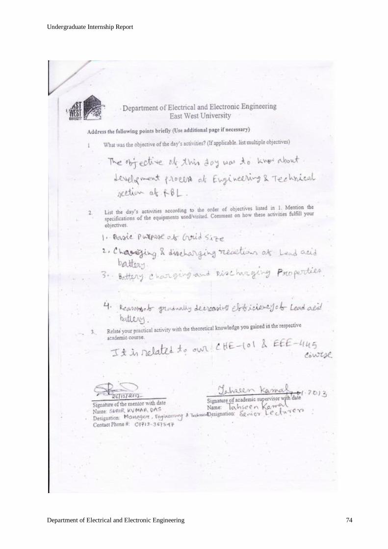
Undergraduate Internship Report
Department of Electrical and Electronic Engineering 74
Undergraduate Internship Report
Department of Electrical and Electronic Engineering 75

Undergraduate Internship Report
Department of Electrical and Electronic Engineering 76

Undergraduate Internship Report
Department of Electrical and Electronic Engineering 77
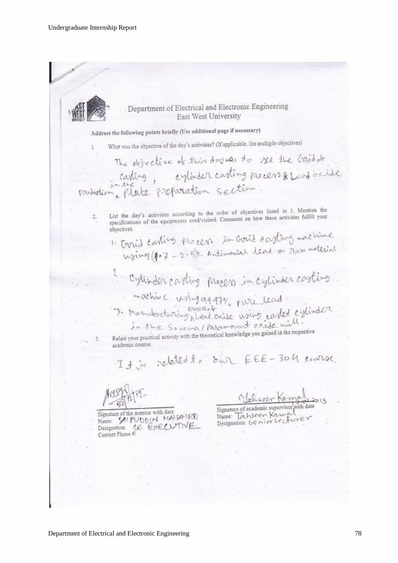
Undergraduate Internship Report
Department of Electrical and Electronic Engineering 78

Undergraduate Internship Report
Department of Electrical and Electronic Engineering 79
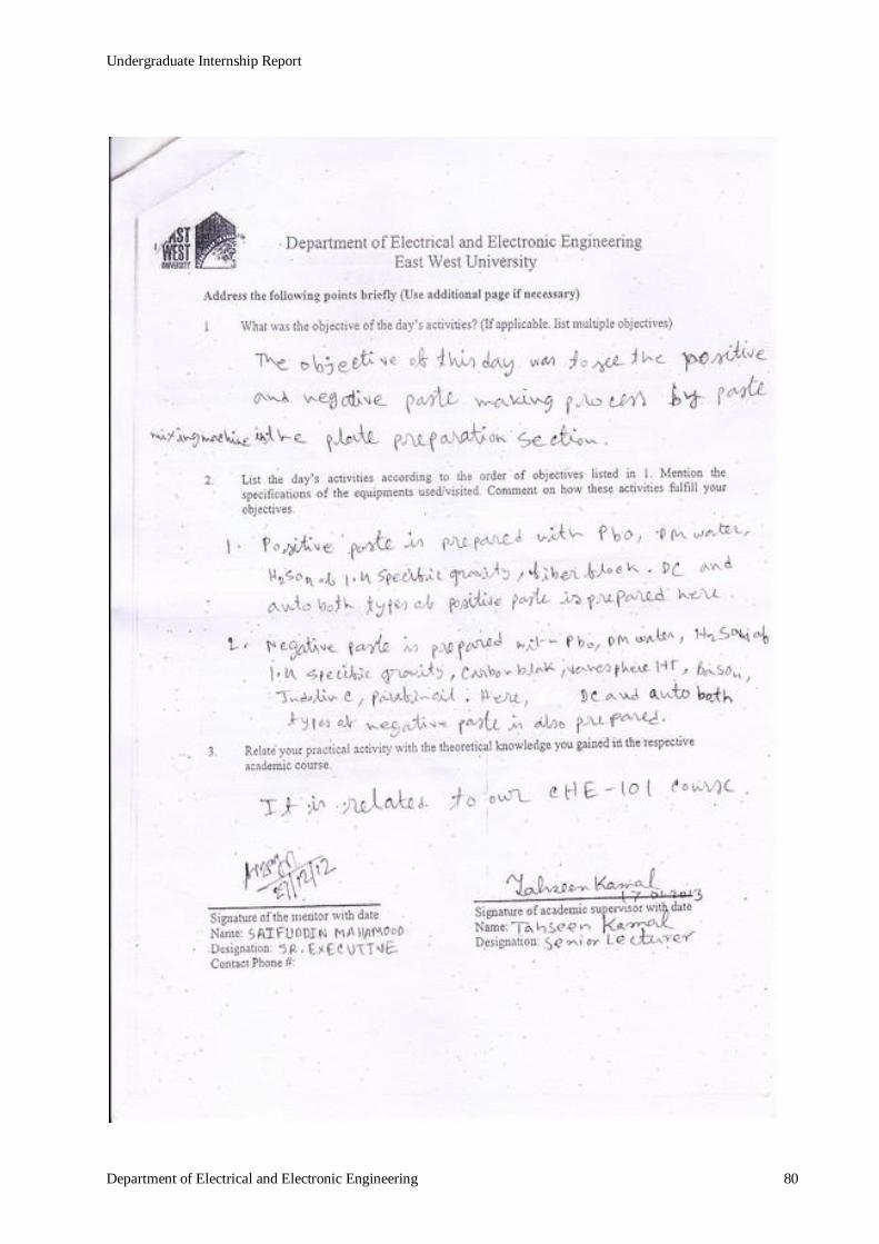
Undergraduate Internship Report
Department of Electrical and Electronic Engineering 80

Undergraduate Internship Report
Department of Electrical and Electronic Engineering 81
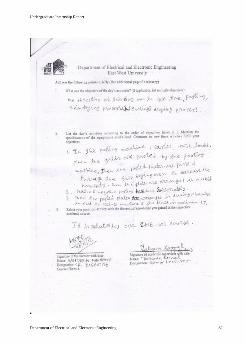
Undergraduate Internship Report
Department of Electrical and Electronic Engineering 82

Undergraduate Internship Report
Department of Electrical and Electronic Engineering 83

Undergraduate Internship Report
Department of Electrical and Electronic Engineering 84

Undergraduate Internship Report
Department of Electrical and Electronic Engineering 85

Undergraduate Internship Report
Department of Electrical and Electronic Engineering 86

Undergraduate Internship Report
Department of Electrical and Electronic Engineering 87
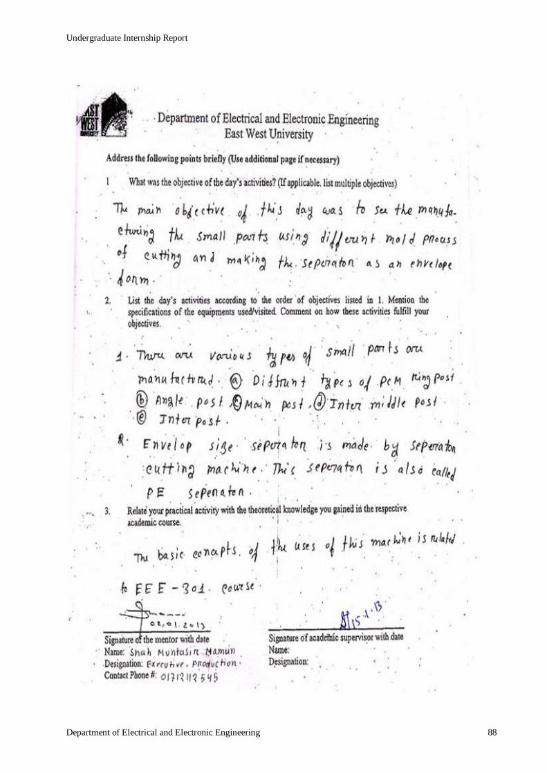
Undergraduate Internship Report
Department of Electrical and Electronic Engineering 88

Undergraduate Internship Report
Department of Electrical and Electronic Engineering 89

Undergraduate Internship Report
Department of Electrical and Electronic Engineering 90
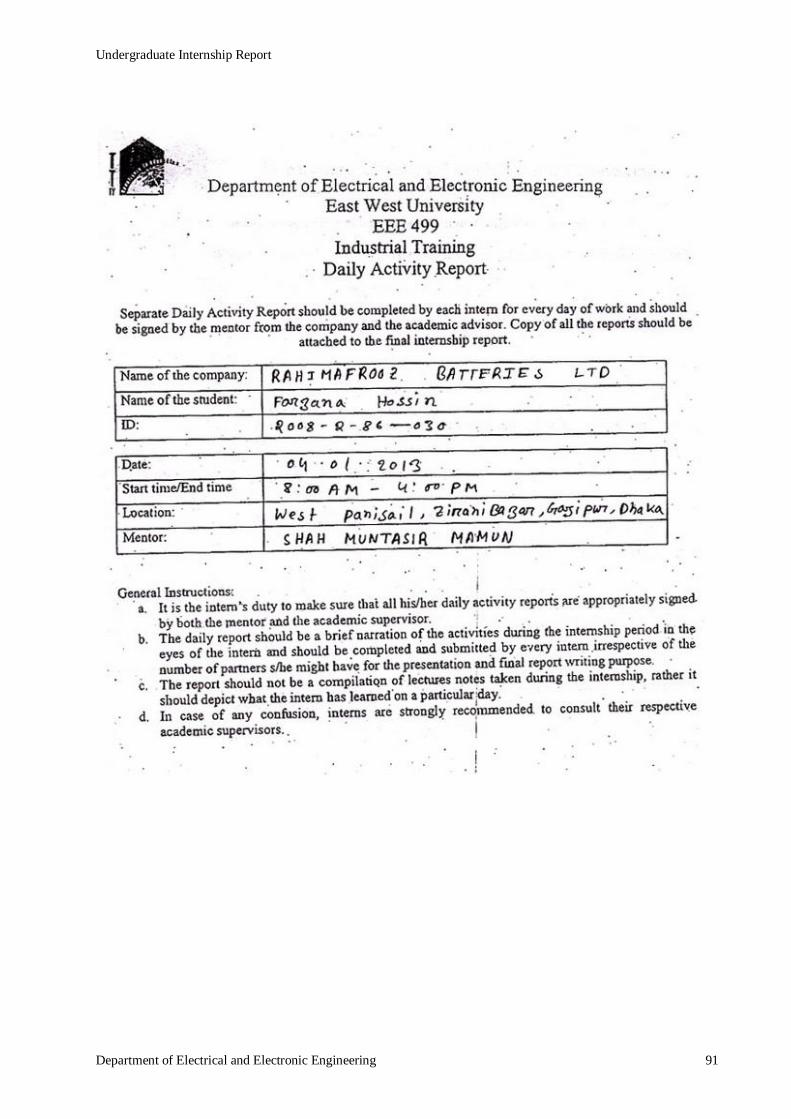
Undergraduate Internship Report
Department of Electrical and Electronic Engineering 91

Undergraduate Internship Report
Department of Electrical and Electronic Engineering 92

Undergraduate Internship Report
Department of Electrical and Electronic Engineering 93
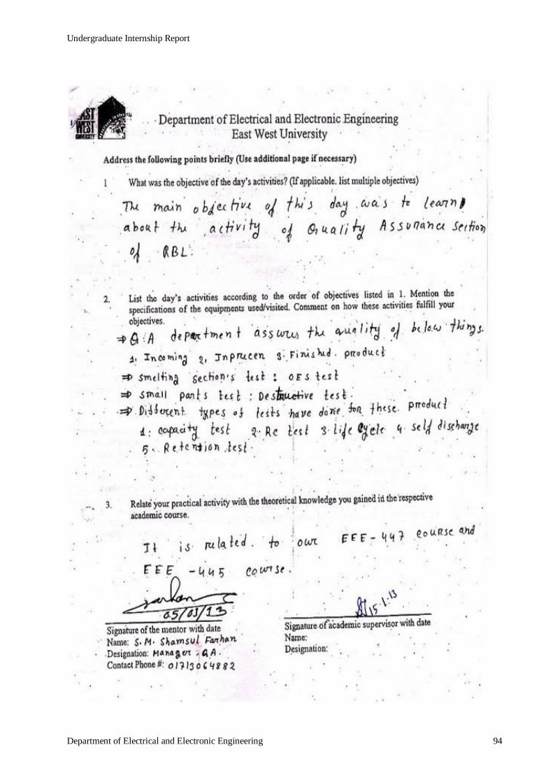
Undergraduate Internship Report
Department of Electrical and Electronic Engineering 94

Undergraduate Internship Report
Department of Electrical and Electronic Engineering 95
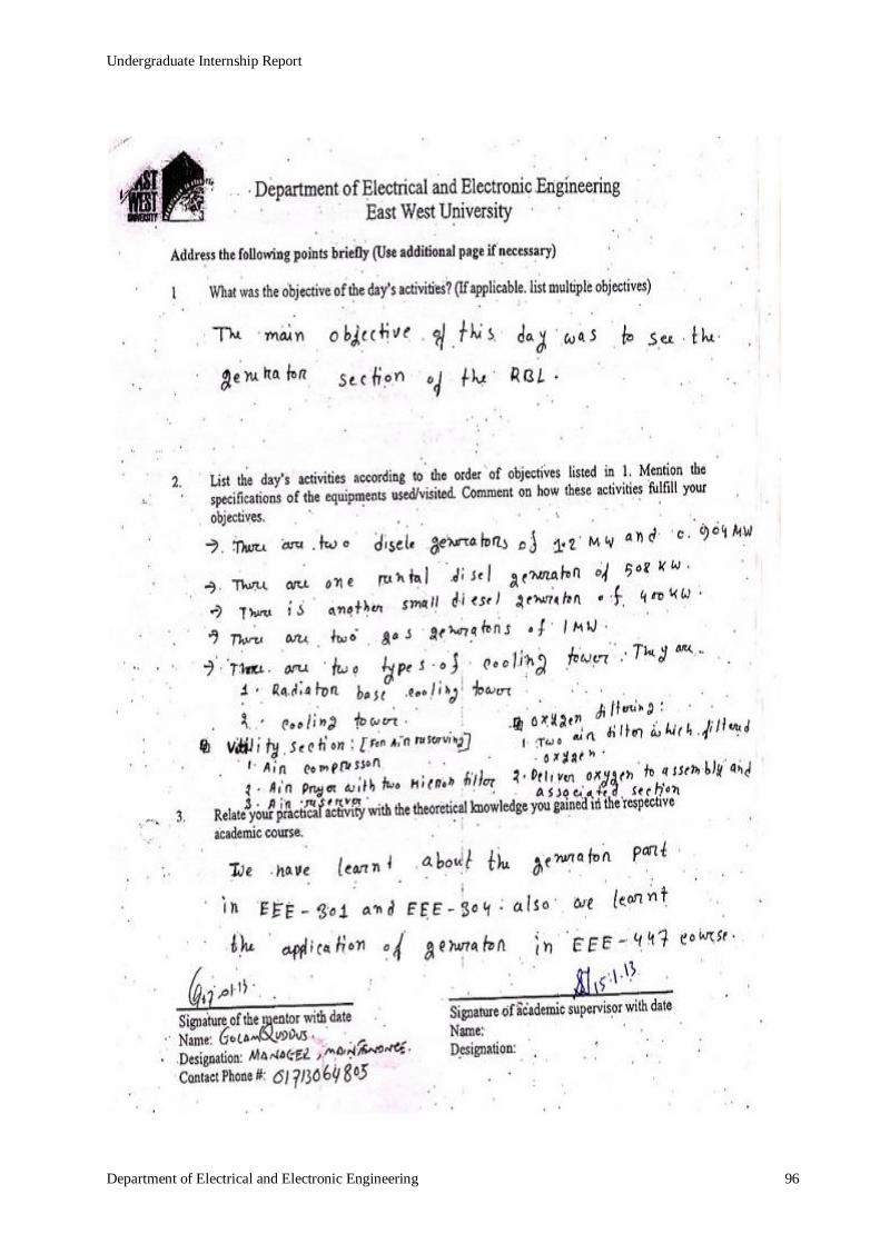
Undergraduate Internship Report
Department of Electrical and Electronic Engineering 96

Undergraduate Internship Report
Department of Electrical and Electronic Engineering 97
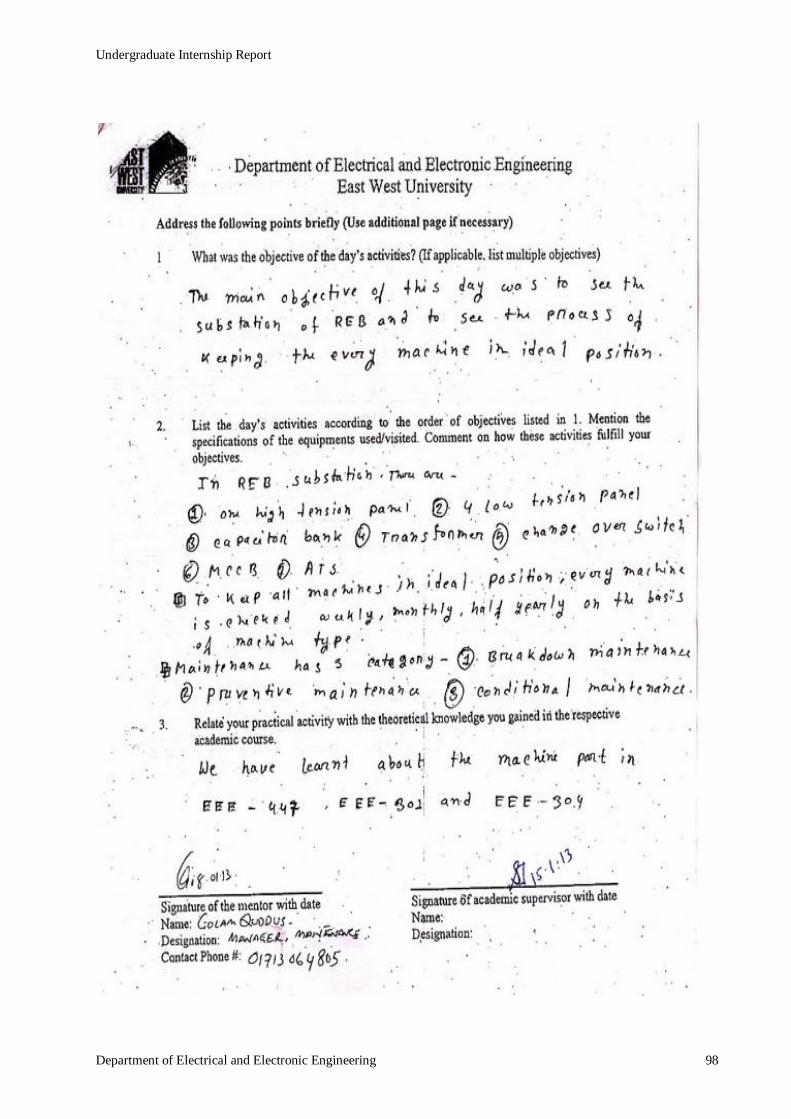
Undergraduate Internship Report
Department of Electrical and Electronic Engineering 98