interoffice memorandum - public works · interoffice memorandum . to: public works commission ....
TRANSCRIPT

1
INTEROFFICE MEMORANDUM
To: Public Works Commission From: Rob Bousfield, Assistant City Engineer Date: September 2, 2015 Subject: Stormwater Design Manual Update
ISSUE Staff is seeking Public Works Commission review and input on proposed updates to the Stormwater Design Manual. Staff will present an update on compliance with the stormwater permit requirements, as well as a summary of the manual revisions.
BACKGROUND
Among the numerous stormwater permit conditions is a requirement for a program to ensure proper stormwater management for new and redevelopment projects. The Stormwater Design Manual is a key component of that program. Engineers and architects use the manual as a guide as they design projects, and staff uses it to review those designs for compliance, and subsequently to inspect the drainage systems as they are constructed.
Due to the distributed responsibilities for stormwater within the region, different agencies have different standards for their area of oversight. This manual provides both requirements and guidance primarily for commercial and multi-family residential projects. The manual addresses new and redevelopment projects, as well as significant maintenance activities. Primary goals of the standards are to protect surface and groundwater quality and to prevent property damage. The manual was published in its current form in 2000 and was most recently updated in 2010.
The 2013 permit includes several substantial changes, including a philosophy that stormwater should be retained on site and infiltrated instead of treated and discharged off-site. A future manual update will address a new permit requirement that all projects retain a 0.6” storm event on-site. However development of an off-site mitigation program (ie: trading program) is desired first as on-site retention will not be practical in all cases. Note that as a practical matter, the existing program has guided the vast majority of projects to retain a 1” storm on site.
The permit requires the manual to be updated in September 2015, so staff has incorporated some of the less complex updates into this first revision. These changes are outlined below.

2
Discussion: Though most projects retain stormwater on-site and infiltrate it, the requirement that every project retain on-site will pose problems in some areas (i.e., downtown). As development of an off-site mitigation/trading program takes time to establish, staff established a two phase approach to updating the manual both to make progress in updating it and to meet the September 2015 update requirement.
Staff formed a Professional Advisory Group (PAG) made up of representatives from technical experts (civil engineers, landscape architect, geotechnical engineer and other agency stormwater experts) to provide input into the revisions. The PAG provided input into which manual updates were important and could be addressed in the permit timeframe.
Following is a summary of key updates, along with discussion for each area:
• Permeable Pavers: Permeable paver systems have been increasing in use, and had previously been permitted as alternative technology. As these are quickly becoming a standard staple in the area, the PAG elected to establish a set of standards for their use. Standards were based primarily upon national standards, though with minor changes based on PAG experience. Standards can be seen in section 3.2.G of the manual.
• Permanent O&M Agreements: One of the focus areas in the new permit is on long-term operation and maintenance of drainage systems. Boise has long required that O&M manuals be prepared along with the system designs and the stormwater ordinance requires property owners to maintain their systems, but the permit requires that an agreement be incorporated into the permit process to ensure that property owners are aware of their obligation and that there is a better enforcement mechanism. The agreement requirement has been noted in the manual sections discussing the O&M manuals (section 2.7) and the sample agreement has been added to the appendices (Appendix J).
• Bioretention Soil Mix: Infiltration swales and basins have been a common solution for many types of projects. Historically these have been constructed of whatever soil is readily available, as long as it infiltrates. A soil mix consisting of sand, compost and soil was developed to provide suitable infiltration rates, stormwater treatment and facilitate plant growth to maximize the potential of bioinfiltration facilities. The use of this soil mix is optional at this point in order to allow the local market to develop and to test the soil mix. Details are in Appendix C.
• General text clarifications: Staff and the PAG used this opportunity for general text clean-up in the manual. The publishing software does not facilitate a red-line version, but changes were more editorial than substantial. One exception is that Section 2.9 attempts to both clarify which maintenance activities require a permit but also establishes a simplified permit process for larger maintenance projects which do not change the nature of the stormwater facilities.
RECOMMENDATION Public Works staff recommends adoption of the updated manual.
MOTION “I move that the Public Works Commission recommend adoption of the updated Stormwater Design Manual.”

2015 Boise Stormwater Design Manual 1September 2015

2015 Boise Stormwater Design Manualii

2015 Boise Stormwater Design Manual iii
1.0 INTRODUCTION PAGE
1.1 Purpose 1-1
1.2 Applicability 1-1
1.3 Inter-Jurisdictional Requirements 1-2
1.4 Authority 1-2
1.5 Modifications and Addenda 1-2
1.6 How to Use This Manual 1-3
2.0 GENERAL STORMWATER REQUIREMENTS
2.1 Introduction 2-1
2.2 Site Planning and Evaluation Requirements 2-1
2.2.A Comprehensive Drainage Plan 2-1
2.2.B Regional Stormwater Controls 2-2
2.2.C Grading Requirements 2-2
2.2.D Drainage Easements and Maintenance Road Access 2-2
2.3 Stormwater Plan Submittal Requirements 2-2
2.4 Plan Review Process and Procedures 2-4
2.4.A Pre-Application Conference 2-4
2.4.B Stormwater Management Plan Review and Approval 2-4
2.4.C Variance Approval Procedure 2-4
2.5 Stormwater Design Criteria 2-5
2.5.A Public Safety Requirements 2-6
2.5.B Water Quantity Design Criteria 2-6
2.5.C Water Quality Design Criteria 2-8
2.6 Operation and Maintenance (O&M) Plan 2-10
2.7 Permanent O&M Agreement 2-11
2.8 Alternative Controls 2-11
2.9 Redevelopment Stormwater Management Criteria 2-12
Table of Contents

2015 Boise Stormwater Design Manualiv
2.10 Stormwater Facility Replacement and Retrofits 2-13
2.10.A Replacing, Retrofitting, or Renovating Infiltration Swales 2-13
2.10.B Replacing, Retrofitting, or Renovating Biofiltration Basins 2-14
2.10.C Replacing, Retrofitting, or Renovating Seepage Beds 2-14
2.10.D Replacing, Retrofitting, or Renovating Wet Detention Ponds 2-14
3.0 STORMWATER SYSTEMS
3.1 Stormwater Conveyance Facilities 3-1
3.1.A General Requirements 3-1
3.1.B Closed Conduits 3-2
3.1.C Open Channels 3-5
3.2 Treatment Facilities 3-7
3.2.A Sand Filters 3-7
3.2.B Biofiltration Swales and Grass Buffer Strips 3-15
3.2.C Oil Separators 3-21
3.2.D Catch Basin Inserts 3-23
3.2.E Infiltration Facilities 3-26
3.3.E.1 General Design Criteria 3-26
3.3.E.2 Infiltration Swales 3-32
3.3.E.3 Infiltration Basin 3-35
3.3.E.4 Seepage Beds 3-37
3.2.F Ponds 3-43
3.4.F.1 General Design Criteria 3-44
3.4.F.2 Dry Detention Ponds 3-48
3.4.F.3 Wet Extended Detention Ponds 3-49
3.4.F.4 Evaporation Pond 3-52
3.2.G Permeable Pavers 3-57
PAGE

2015 Boise Stormwater Design Manual v
APPENDICESA. Determining Peak Discharge, Peak Volume, & the Water Quality Volume A-1
B. Calculations For Facility Sizing B-1
C. Bioretention Soil Mix (BSM) Requirements C-1
D. Hydrologic and Hydraulic Graphs D-1
E. General Testing Procedures E-1
F. Groundwater Sensitivity for Subsurface Seepage Systems F-1
G. Values of Roughness Coefficient G-1
H. Mosquito Abatement H-1
I. Installing Infiltration Facilities Strategies for Success I-1
J. Permanent Operation and Maintenance (O&M) Agreement J-1
K. Glossary K-1
L. References L-1
LIST OF TABLES2-1 Design Storm Frequencies - Water Quality and Water Quantity 2-5
2-2 Values for Calculating Peak Flow Rates and Peak Volumes 2-7
2-3 TSS Removal Rates for Surface Water Management BMPs 2-9
3-1 Performance Criteria and Evaluation Methods for Catch Basin Inserts 3-19
A-1 Recommended “C” Coefficients for “Rational Method Equation” A-3
B-1 Evaporation Pond Calculations B-4
G-1 Computation of Roughness Coefficent: Channel Conditions G-1
G-2 Computation of Roughness Coefficent: Closed Conduits Flowing Partly Full G-2
G-3 Computation of Roughness Coefficent: Lined or Built Up Channels G-4
G-4 Computation of Roughness Coefficent: Excavated or Dredged G-5
G-5 Computation of Roughness Coefficent: Natural Streams G-6
LIST OF FIGURES2.1 Stormwater Management Checklist 2-3
3.1 Austin Sand Filter 3-9
3.2 Delaware Sand Filter 3-10
3.3 Underground Sand Filter 3-11
3.4 Pocket Sand Filter 3-12
3.5 Biofiltration Swale 3-16
3.6 Grass Filter Strip 3-17
3.7 Coalescing Plate Oil Separator 3-21
PAGE

2015 Boise Stormwater Design Manualvi
3.8 Oil Separator 3-22
3.9 Shallow Trenches 3-24
3.10 Deep Boreholes 3-24
3.11 Infiltration Swale 3-33
3.12 Infiltration Basin 3-34
3.13 Seepage Bed (Sheet 1 of 2) 3-35
Seepage Bed (Sheet 2 of 2) 3-36
3.14 Safety and Aquatic Bench 3-43
3.15 Dry Detention Pond 3-45
3.16 Wet Extended Detention Pond 3-46
3.17 Evaporation Pond 3-47
3.18 Permeable Interlocking Concrete Pavers (PICP) 3-53
PAGE

2015 Boise Stormwater Design Manual 1-1
The Stormwater Design Manual (MANUAL) defines minimum standards, requirements, and procedures for the design, permitting, construction,and
maintenance of drainage systems within the jurisdiction of the city of Boise (City) in accordance to the City’s Stormwater Management and Discharge Control Ordinance (ORDINANCE), Chapter 8-15 and other City ordinances.
This MANUAL presents minimum stormwater standards that apply to physical development within the City. However, the standards will not apply for all situations. Compliance with these standards does not relieve the applicant of the responsibility to use sound professional judgment or compliance with other local, state, or federal requirements. The City intends for these standards to assist, but not substitute for, competent work by design professionals.
The purposes of drainage systems are:
• limit peak post-development stormwater flows
• treat stormwater
• mitigate the impacts of runoff due to additional impervious surfaces
• maximize infiltration (e.g., minimize runoff) from developed property
• facilitate groundwater recharge
• protect surface and groundwater quality
The standards in this MANUAL apply to new development and redevelopment projects that require building permit approval by the City. The City has responsibility for drainage plan review for the following development and re-development projects:
• industrial
• commercial
• institutional
• multi-family residential development (not part of a larger subdivision project)
• subdivision projects with private streets and/or non-street drainage
• new projects that have greater than 1000 square feet of impervious area
• re-development projects that modifies greater than 1000 square feet or 10% of the impervious area
The City will review all stormwater related submittals for general compliance with these specific standards. An acceptance by the City does not relieve the applicant from the responsibility of ensuring all systems are safe and that calculations, plans, specifications, construction, and record drawings comply with normal engineering standards, this MANUAL, and other applicable local, state, and federal rules and regulations. Where any other law, ordinance, resolution, rule, or regulations of any kind also cover requirements in this document, the more restrictive shall govern. This MANUAL replaces the 2010 version of the MANUAL.
The Assistant City Engineer may require more stringent requirements than would normally be required under these standards depending on special
1. 0 INTRODUCTION
1. 2 Applicability
1.1 Purpose
PAGE

2015 Boise Stormwater Design Manual1-2
conditions and/or environmental constraints. The Assistant City Engineer has the option of accepting alternatives to the MANUAL standard plans, specifications, and design details if the alternatives proposed meet or exceed the adopted performance standards.
For projects governed by other jurisdictions (e.g., the Ada County Highway District (ACHD) or a drainage district), the applicant must comply with their standards and requirements and receive approval from those entities. The applicant shall provide proof of such approval to the City as deemed necessary in order to be exempt from these requirements.
Agencies receiving stormwater discharges should enter into discharge agreements with the applicant to ensure that the receiving agency will maintain long-term water quality control over the stormwater discharges they receive.
The Clean Water Act of 1972, as amended in 1987, prohibits the discharge of pollutants into waters of the United States unless the discharge complies with the National Pollutant Discharge Elimination System (NPDES) permit. The City is subject to the Phase 1 Stormwater NPDES permitting requirements and, along with five other co-permittees issued by the Federal Environmental Protection Agency (EPA) November 2000 (IDS-02756-1). Copermittees include the City, Garden City, ACHD, Idaho Transportation Department District 3 (ITD3), Boise State University (BSU), and Ada County Drainage District 3 (DD3). The Federal NPDES permit program requires the City to “develop, implement, and enforce controls to reduce the discharge of pollutants from municipal separate storm sewers that receive discharges from areas of new development and significant redevelopment.” Within this regulatory context, the City implements development requirements that reduce water pollution carried in stormwater runoff. This MANUAL establishes stormwater Best Management Practices (BMPs) that includes direct conveyance (channel or pipe flow), storage (detention), filtration (for off-site discharge), and infiltration (for on-site discharge), or BMPs that combines two or more of these methods.
Laws that provide the City with the authority to regulate drainage within the City’s jurisdiction include, but are not limited to the following:
• constitutional authority as a municipal corporation to promulgate regulations governing the discharge of stormwater
• the City’s ORDINANCE, Chapter 8-15 of the City Code gives the City the authority to regulate stormwater runoff quality
• Idaho Code 50-331, 50-332, 50-333, 50-334, 50-315, 50-317, 50-323 authorizes the City to control and secure the City’s drains
• Idaho Code 67-6518 authorizes the City to adopt standards for storm sewer system
1. 3 Inter-Jurisdictional Requirements
1. 4 Authority

2015 Boise Stormwater Design Manual 1-3
The City shall revise and update this MANUAL as necessary through approval by the City Council to reflect corrections and advances in the field of drainage engineering and water resources management. Users who request changes to the MANUAL shall provide data to the City that supports justification for the change.
This MANUAL specifies drainage requirements for new development and significant redevelopment sites. The MANUAL will provide the design engineer the resources and regulatory information necessary to develop a unique site plan based on specific site conditions.
Section 1 describes the regulatory and jurisdictional scope for these design requirements. Section 2 presents the general requirements that apply to all sites that require a City drainage permit. Section 3 contains the individual drainage facility designs (e.g., the system(s)) selected for installation.
1. 5 Modifications and Addenda
1. 6 How to Use this Manual

2015 Boise Stormwater Design Manual1-4
2015 Boise Stormwater Design Manual 2-1
This chapter identifies general drainage system requirements for all new development and redevelopment projects regulated by Boise City (City).
Design professionals, policy makers, and elected officials recognize that site planning and design that prevents or reduces stormwater runoff is the most cost effective strategy for stormwater management. Because of this, the City encourages onsite infiltration for all site designs.
Specific site conditions, constraints, or plans for future improvements may reduce stormwater management options. Site designers and plan reviewers need to understand site conditions before, during, and after site development. This understanding provides the basis for selecting proper site controls. The Stormwater Management (SWM) plan describes specific site conditions required by the stormwater management checklist. The following is a partial list of site factors that may guide stormwater system design:
• permeability and types of soil and subsurface materials underlying the Best Management Practice (BMP)
• size of the drainage area served and the runoff volume in relation to the size of the BMP
• slope and geometry of the site
• proximity and classification of bedrock beneath the bottom of the BMP
• proximity of the seasonal high ground water table beneath the bottom of the BMP
• land uses and potential contaminant types
• proximity to surface water
• proximity to public and private drinking water supply wells and distribution lines
• site specific factors related to past use, including soil and ground water contamination
A comprehensive drainage plan is required for all phased developments and for sites greater than 10 acres. The comprehensive drainage plan shall:
• characterize the site development
• show how the SWM plan will be met for each and all anticipated developments projected on the site covered by the comprehensive drainage plan (e.g., for each phase of the development)
2. 0 GENERAL
STORMWATER REQUIREMENTS
2. 2 Site Planning
and Evaluation Requirements
2. 2.A Comprehensive
Drainage Plan
2. 1 Introduction

2015 Boise Stormwater Design Manual2-2
Regional stormwater controls may be appropriate in some circumstances, though local controls are usually preferred. Prospective developers are responsible for funding regional control facilities. The design of any regional control facility must provide for the reasonable development of property in the entire upstream watershed. The peak outflow of a regional facility is determined by using a hydrologic model of the watershed consistent with the protection of the downstream watershed areas. Regional facility construction must conform to an approved master drainage plan. Review and approval is required from all impacted jurisdictions.
Site grading shall not create or contribute to flooding, erosion, increased turbidity, siltation, or other forms of pollution in a watercourse. When filling, excavating, dredging or moving of earth materials alters the existing grade of a site, the owner shall protect all adjoining property during and after construction. The tops and toes of graded slopes shall be set back from property boundaries and structures as required by International Building Code Chapter 18 and Appendix J as amended by Boise City Building Code Chapter 4-02 or unless permitted by a specific easement. Setbacks are necessary in order to ensure safety, provide adequate foundation support, and prevent damage resulting from water runoff or erosion.
Parking lot grades shall be a minimum of 1% for asphalt and 0.4% for concrete. Traffic rated manhole lids are required.
All stormwater control facilities and natural drainage channels shall be located in designated and reserved stormwater easements. Easements shall be located to provide access for routine inspection and shall be sized for access of construction equipment and activities that may be needed for maintenance and repair work. If maintenance roads are necessary, they must be a minimum of 12’ wide, must have an HS-25 load capacity, and a minimum inside turning radius of 30’.
A SWM plan is required for new development and redevelopment projects. A qualified Idaho licensed professional competent in the subject matter must stamp and sign the SWM plan. A complete SWM plan is required for building permit applications and is to include all of the components listed in Figure 2.1, Stormwater Management Checklist (Checklist).
The SWM plan shall clearly state the number and timing of City inspections necessary to ensure their proper installation. For infiltration facilities, including seepage beds, inspections should be conducted when the site is excavated (when the pit is opened up); when the drainpipe with rocks are placed; and when the system is covered.
Figure 2.1 lists the requirements that apply to stormwater systems. Applicants shall submit the general information identified in the checklist and shall also submit additional information specific to the type(s) of system(s) installed that verifies compliance with MANUAL standards
2.2.B Regional Stormwater Controls
2.2.C Grading Requirements
2.2.D Drainage Easements and Maintenance Road Access
2.3 Stormwater Plan Submittal Requirements
Stormwater Management Plan Checklist

2015 Boise Stormwater Design Manual 2-3
Drainage Report☐ Prepared and stamped by a qualified Idaho licensed professional
☐ Narration for basis of selection and operation of the drainage design
☐ Pre- and post-development peak flow rate calculations
☐ Pre- and post-development runoff volume calculations
☐ Copies of associated permits, easements, and discharge agreements
☐ A copy of the site’s Phase 1 Site Assessment (if available)
☐ Infiltration facilities: two copies of Geotechnical Report (Section 3.2.E)
☐ Comprehensive drainage plans (greater than 10 acres); flood routing and computations for the 100 year flood through the site
☐ Multi-phase developments: the drainage report must include pertinent data from other phases
Drainage Plan☐ Five copies of the complete drainage plan, including detail sheets, are to
be submitted (unless submitted through ePlan)1.
☐ Topographic map using NAVD-88 datum (if possible) of pre-development and finished grade contours at 1’ or 2’ intervals2
☐ Onsite proposed building elevations of adjoining lots & finish floors
☐ Grade of all impervious surfaces
☐ Existing drainage and irrigation water conveyance systems within the property line or developed site
☐ New or modified drainage systems including system dimensions, profiles, elevations or spot elevations at key locations
☐ Standard note on the plans requiring the construction stage and scheduling of drainage facility inspections by the Boise Public Works Department3
☐ Infiltration facilities: standard note requiring that the bottom of the system be constructed at least 12” into free draining material
☐ Operation and Maintenance (O&M) plan
☐ Operation and Maintenance (O&M) Permanent Agreement
1 The ePlanReview system allows customers to submit plans online. Planning and Development Services (PDS) and other reviewing agencies review plans simultaneously, thus reducing review times. Contact PDS for ePlan review requirements.
2 Greater contour intervals may be used on steeper slopes if the grade information is unreadable.3 Contractors must provide a 24-hour notice to the Boise Public Works Department.
Figure 2.1 Stormwater management
Plan CheCkliSt

2015 Boise Stormwater Design Manual2-4
The City recommends that applicants schedule a pre-application conference to expedite building permit review. A conference is recommended when an applicant is new to the drainage permit process; a large (e.g., greater than 10 acres) development or redevelopment is planned; or special conditions or problems have become apparent during the site evaluation, or where alternative stormwater systems are being considered.
2.4.A Pre application Conference
The City will review all SWM plans for compliance with MANUAL requirements. Approval by the City does not relieve applicants from responsibility for ensuring system performance, safety, and compliance with other local, state, and federal regulations. Applicants shall ensure that calculations, designs, specifications, construction, and record drawings comply with acceptable engineering standards and this MANUAL. City approval does not constitute a guarantee of system performance nor does it relieve the applicant of liability for the sufficiency, suitability or performance of facilities. For projects regulated by other jurisdictions, such as Ada County Highway District (ACHD) or an irrigation/drainage district, applicants must comply with any additional or varying requirements and receive approval from those entities. Applicants shall provide proof of approval to the City as deemed necessary.
2.4.B Stormwater Management Plan Review and Approval
2.4.C Variance Approval Procedure
Compliance with these standards for some developments or sites may be unfeasible. In these situations, the developer or engineer can request a variance from the MANUAL standards. Variance requests shall be submitted in writing to the Assistant City Engineer. The City’s decision to grant, deny, or modify the proposed variance shall be made within 10 working days of receipt of request based upon evidence that the variance request meets all of the following criteria:
• the applicant is subject to special circumstances that are peculiar to the applicant’s system or situation and not caused by the applicant’s actions
• substantial undue hardship would result from requiring strict compliance with the MANUAL requirements and deprive the applicant of rights commonly enjoyed by other persons similarly situated under the terms of the ORDINANCE
• the proposed variance protects public health, safety and welfare to extent similar to the MANUAL requirement(s)
• the proposed variance will achieve the intended results of the MANUAL standards through a comparable or superior design
• the change will not adversely affect the ability to operate and maintain the system
A written appeal of the Assistant City Engineer’s decision may be submitted to the Public Works Commission within 10 working days of receipt of the decision.
2.4 Plan Review Process and Procedures

2015 Boise Stormwater Design Manual 2-5
The City Council has adopted the Stormwater Management and Discharge Ordinance (ORDINANCE) to “protect and enhance the water quality of our watercourses, water bodies, groundwater, and wetlands”… and to “minimize the discharge and transport of pollutants to storm drains” (BCC 8-15). New development and redevelopment standards apply to surface and subsurface management of stormwater. Designs comply with the City’s Stormwater Management requirements when:
• good housekeeping, source controls, and maintenance practices are applied in accordance with the Boise Non-Stormwater BMP Handbook (Visit www.PartnersforCleanWater.org) to prevent or reduce pollutants from entering storm drains
• the water quantity volume is captured and the water quality design flow is treated stormwater system in accordance with this MANUAL
• the stormwater system is installed, operated, and maintained according to the original design and according to the O&M plan, the Permanent O&M Agreement, and the ORDINANCE.
Stormwater systems may include storage (detention), filtration (for offsite discharge), and onsite infiltration, or may combine two or more of these methods. This MANUAL addresses onsite controls and offsite controls. Stormwater system designs shall maintain or lessen pre-development discharges in applicable circumstances. The City reviews all designs for both onsite and offsite discharges.
Table 2-1 summarizes design storm criteria. Calculation methodologies to determine the storm criteria include the Rational Method and the Natural Resources Conservation Service (NRCS) TR-55 method with a 24 hour design storm. The Rational Method or approved derivatives can be used to calculate the peak flow rate for areas less than 100 acres, the NRCS TR-55 Method with a 24 hour design storm can be used to calculate the peak flow rate for projects up to 25 square miles in size.
Other hydrologic methods may be acceptable for determining runoff rate and volume. However, if an alternate hydrologic method is selected, the design professional shall obtain approval from the City prior to beginning hydrology studies.
2.5 Stormwater
Design Criteria
Location or Type Return Frequency
of Development Primary Conveyance System
Secondary Conveyance System
Water Quality Storage Systems
Water Quality Treatment Systems*
Areas with < 15% slope and new devel-opment< 10 acres
50 year 100 year 50 year 0.34”
Areas with > 15% slope or new devel-opment > 10 acres; foothill development
100 year 100 year 100 year 0.34”
*Depth for one storm. Water quality treatment depth is based on the City’s goal to fully treat at least 80% of the storms annually (i.e. 80% of daily storm events are estimated to have a depth of 0.34” or less)
table 2-1 DeSign Storm
FrequenCieS - water quality anD water
quantity

2015 Boise Stormwater Design Manual2-6
All stormwater control facilities shall incorporate safety measures in their design. These may include, but not be limited to fencing, warning signs, a stadia rod indicating depth at lowest point, and outlet structures designed to limit public access.
In general, the rate of stormwater runoff from any proposed land development shall not exceed the rate of runoff prior to the proposed land development regardless of the storm event evaluated. The City may allow an increase to this flow rate if the receiving jurisdiction provides written permission to discharge the treated design storm volume at a higher rate.
Submitted drainage designs shall provide the pre- and post-development flow rate calculations for the 2, 5, 10, and 50 year storm events at sites less than 10 acres. The pre- and post-development flow rate calculations for the 2, 5, 10, 50, and 100 year storm event are required at hillside development areas and sites greater than 10 acres (sites with comprehensive plans). Site designs should also take post construction impacts from landscaping irrigation into account when sizing stormwater facilities.
Designs for outlets from detention facilities must replicate pre-development discharge conditions at sites less than 10 acres for 2, 5, 10, and 50 year storm events, and at sites greater than 10 acres or with comprehensive plans for 2, 5, 10, 50, and 100 year storm events. An evaluation of several storm event sizes is required to ensure the detention facility outlets are properly designed.
A runoff rate of 0.05 cfs/acre may be used for computational methodologies that result in zero runoff rates for the two year pre-development storm. Entities that own or control the receiving body or jurisdiction for offsite discharges may have more stringent runoff standards (e.g. rates < 0.05 cfs/acre). In this case, the more stringent standards shall apply.
Designs of conveyance systems shall accommodate the peak flow of the design storm frequency in Table 2-1. Primary conveyance systems should convey the design storm with minimum impact or inconvenience to the public. Secondary conveyance systems may convey the design storm with some impacts and inconvenience to the development. Potential impacts and inconveniences of the secondary conveyance system must be defined. The design of the secondary conveyance must also include easements and restrictions to protect the water conveyance system into perpetuity. If the owner does not obtain the easements and restrictions necessary for the secondary conveyance, the primary conveyance system must accommodate both the primary and secondary flows.
Stormwater discharges shall not be directed on to any adjacent property that has not received the runoff previously (under pre-development conditions) unless the adjacent property owner provides an easement, consent, and/or onsite retention. Furthermore, runoff from a proposed development cannot be diverted and released to any other conveyance, storm drain, or drainage facility unless specific consent and approval in writing (signed agreement) is granted by the entity that controls such conveyance, storm drain, or drainage facility. City review for these agreements and conditions is required prior to final approval.
Table 2-2 show the values that should be used for the Rational Method and the TR-55 method for calculating peak flows and peak volumes.
2.5.B Water Quantity Design Criteria
2.5.A Public Safety Requirements

2015 Boise Stormwater Design Manual 2-7
table 2-2 ValueS For CalCulating
Peak Flow rateS anD Peak VolumeS
Type of MethodDevelopment Rational Method NRCS TR-55
Peak Flow RatesAreas with < 15% slope and new development< 10 acres
Based on time of concentration and associated intensity for a 50-year design storm frequency 4.. The time of concentration cannot be less than ten minutes.
Based on a 24-hour, 50-year storm with a Type II Distribution 5.
Peak Flow VolumesBased on a one-hour, 50-year design storm frequency (e.g., an intensity of approx. 1” per hour)
Based on a 24-hour, 50-year storm with a Type II Distribution 5.
Areas with > 15% slope or new develop-ment > 10 acres;
Peak Flow RatesBased on time of concentration for a 100-year design storm frequency. The time of concentration cannot be less than 10 minutes
Based on a 24-hour, 50-year storm with a Type II Distribution 5.
Peak Flow VolumesBased on a one-hour, 100-year design storm frequency (e.g., an intensity of approx. 1.1” per hour)
Based on a 24-hour, 100-year storm with a Type II Distribution 5
4 Intensities are based on the Rainfall Intensity, Duration, and Frequency Relationship (Appendix C).5Rainfall amounts for this storm shall be as shown in the National Oceanic and Atmospheric Administration (NOAA) Atlas 2

2015 Boise Stormwater Design Manual2-8
Surface Water Design Criteria
2.5.C Water Quality Design Criteria
This MANUAL applies different standards to subsurface and surface treatment and disposal of stormwater. For example, off-site stormwater discharges require basic water quality treatment to achieve an 80% reduction of Total Suspended Solids (TSS) based on the removal rates included on Table 2-3. While infiltration facilities for on-site stormwater discharges automatically satisfy this basic water quality treatment for TSS, additional stormwater treatment measures to protect ground water quality are required (e.g., adequate sand filtration and/or distance to high water table elevation).
Stormwater runoff can be treated and disposed of through infiltration by using sand filters, infiltration swales, infiltration basins, seepage beds, or permeable paving systems. The infiltration system shall retain the entire water quantity volume on the site unless offsite discharges are otherwise permitted by the receiving property owner and City.
Infiltration facilities have minimum separation distances to groundwater. See Chapter 3.2.E, Infiltration Facilities for requirements by type of facility. Infiltration facilities are required to empty within 48 hours following design storm events in order to comply with the City’s quantity management and mosquito abatement goals.
In addition to City requirements, the Idaho Department of Water Resources (IDWR) has shallow and deep injection well requirements as part of the Underground Injection Control Program. Shallow injection wells include seepage beds. Shallow injection wells must be inventoried with IDWR. This inventory requirement is included in the City’s building permit process.
Infiltration facilities are considered deep injection wells when they are deeper than 18 feet. Deep injection wells must have an approved injection well permit prior to approval. Contact IDWR for permit requirements.
For all development, the Rational Method will be used for peak flow rates and volumes for offsite discharges during post development conditions based on a design storm of 0.34” per hour with a duration of one hour.
New development and redevelopment projects with offsite discharges are required to install stormwater systems that, alone or in combination with others BMPs, reduce or remove TSS by 80%. The design removal rates listed in Table 2-3 are currently accepted by the City.
As noted in Table 2-3, TSS removal rates of catch basin inserts, gravity separators, vault filtration systems or other emerging technologies vary and will be assessed based on the manufacturer’s test data at the water quality design flow rate and TSS concentration of between 100 and 150 mg/l (approximate median TSS concentration typically found for this region), when available. Please refer to the discussion of proprietary systems in Section 2.8, Alternative Controls, if one of these systems is proposed.
Subsurface Water Design Criteria

2015 Boise Stormwater Design Manual 2-9
BMP TSS Removal for Design Storm Volume
Comments
Sand Filter 80% Pretreatment for offsite discharges or infiltration of water quality volume
Biofiltration Swale 80% Pretreatment for offsite discharges; sediment forebay included or flow path lengthened for additional sediment removal
Grass Buffer (Filter) Strip 85% Pretreatment for offsite discharges; removal rate based on 150’ buffer lengths
Oil Separator 15% Pretreatment for offsite discharges
Catch Basin Insert(including geosynthetic fabric filters)
Varies Pretreatment for offsite discharges
Gravity Separator Varies Pretreatment for offsite discharges
Vault Filtration System Varies Pretreatment for offsite discharges
Dry Detention Pond 15% Water quality control pond
Wet Extended Detention Pond 80% Sediment forebay included or flow path lengthened for additional sediment removal
Evaporation Pond 100% Full retention of water quality volume
Permeable Interlocking Concrete Pavers (PICP)
80% Pretreatment for offsite discharges or infiltration of water quality volume
Hydrodynamic Separator 80% See 2.8, Alternative Controls
Land Uses with High Potential
Pollutant Loads
Onsite infiltration stormwater systems address sediment and other pollutants associated with sediment for 100% of the volume infiltrated. The amount (volume) infiltrated is either the water quality design volume (0.34”) or the full water quantity design volume (1 hour 50-year return event for sites less than 10 acres, or the 1 hour 100 year return event volume for sites greater than 10 acres). Additional treatment prior to infiltration for additional nutrient removal, metals, or toxic materials based on receiving water body requirement or site uses may be considered in the future, but are not required by the City at this time.
Stormwater systems located at sites with certain planned land use categories may generate higher pollutant loads than systems located at other types of sites. The City’s drainage permit review will evaluate the potential to contribute pollutants to stormwater, for both offsite and onsite treatment systems. Land use categories considered to have a potential for significant sources of pollutants include:
table 2-3 tSS remoVal rateS For SurFaCe water
management bmPS

2015 Boise Stormwater Design Manual2-10
• vehicle service, maintenance and equipment cleaning, salvage yards (auto recycle facilities), fueling, fuel transfer facilities, and parts stores
• fleet storage areas (cars, buses, trucks)
• industrial machinery yards and equipment maintenance
• railroad yards and equipment maintenance
• road salt storage and loading areas (if exposed to rainfall)
• commercial nurseries
• outdoor storage and loading/unloading areas of hazardous substances
• aircraft storage, use, and maintenance areas
• construction businesses (paving, heavy equipment storage and maintenance, storage of petroleum products)
• bulk material sales (landscape, rock/sand products)
• full service and limited service restaurants
• concrete, painting, excavation contractor facilities
• industrial facilities that are required to obtain an NPDES multi-sector industrial general storm water permit
Stormwater discharges from land uses with higher potential pollutant loads require:
• applicable treatment systems for the expected pollutants to protect the surface or ground water receiving water body (e.g., onsite or offsite discharges), including catch basin inserts, oil separators, sumps, sand filtration, and/or biofiltration swales
• applicable operation and maintenance practices, including good housekeeping, source controls, and regular inspections
The O&M plan shall identify specific maintenance techniques and schedules for each type of system used on the site. At a minimum, the O&M plan shall identify the following:
• the stormwater system owner(s)
• the entity, party or parties, responsible for long term operation and maintenance
• a copy of final system drawing designs along with design calculations (not needed during plan review)
• a list of source controls
• the location and type of stormwater system, using both narrative and a map
• how the stormwater system operates
• a schedule of inspection and maintenance for routine and non-routine maintenance tasks to be conducted
• system failure and replacement criteria to define the structure’s performance requirements
2.6 Operation and Maintenance (O&M) Plan

2015 Boise Stormwater Design Manual 2-11
Ongoing facility O&M is a condition of design review. The property owner shall provide copies of the approved O&M plan to the parties responsible for O&M of the system. In addition, the responsible party must also provide access to facility for inspections and review of operation and maintenance activities.
The O&M plan must clarify that records of inspections and maintenance are required. Facility operators responsible for operation and maintenance of the system shall retain and maintain these records for the most recent five year period. The requirements for maintenance and record keeping apply to all stormwater systems located at the site.
Facility operators responsible for operation and maintenance shall con-duct regularly scheduled inspections, clean, and maintain the system when necessary to ensure operation according to the original design. For above ground infiltration facilities (e.g., swales) the O&M plan shall identify maximum allowable sediment depth and methods for testing and disposal of accumulated sediments.
The O&M plan must also clarify that facility managers and owners must develop an understanding of the pollutant concentrations for the sediment cleaned from their stormwater systems (e.g., through testing) to ensure proper disposal. The O&M plan must also clarify that the stormwater system sediment testing prior to disposal may be required depending on the land use.
The City Operation and Maintenance Resource Guide provides sediment testing and proper disposal protocols. Visit www.partnersforcleanwater.org for more information.
The applicant shall submit an executed Permanent O&M agreement as part of the final SWM plan. The Agreement is legally enforceable and transferable. The agreement assigns permanent responsibility for maintenance of structural and treatment controls. See Appendix J, Permanent Operations and Maintenance Agreement, for more information.
Stormwater facilities and controls other than those identified in this MANUAL may be proposed in the following situations (or as recommended by the Assistant City Engineer)
• where site constraints make it difficult to achieve the stormwater management standards with conventional systems
• where a new technology may provide a higher level of treatment or performance
When a new technology is proposed, the applicant shall submit the following additional information to the City:
A. Description of the alternative technology or product including:
1. size
2. technical description
3. capital costs
4. design life
2.8 Alternative Controls
2.7 Permanent
O&M Agreement

2015 Boise Stormwater Design Manual2-12
2.9 Redevelopment Stormwater Management Criteria
5. installation process and costs (describe consequences if installed improperly, etc.)
6. O&M requirements and costs
B. Data on the effectiveness of the alternative technology:
1. data from laboratory testing and pilot or full scale operation, and calculation of pollutant removal rate (e.g., TSS for offsite discharges). Washington State Dept. of Ecology and New Jersey Dept. of Environmental Protection administer verification programs for alternative or emerging controls. Information about verified technologies can be found on their websites.
2. operational details on any full scale installations
C. Validation Information:
1. articles from peer review, scientific, or engineering journals
2. any approvals or permits from other authorities
3. references from other installations
4. a monitoring plan to demonstrate BMP effectiveness
City staff will assess proprietary system pollutant removal based on the manufacturer’s test data at the design flow rate and at the median TSS concentration typically found for this region.
The ORDINANCE defines redevelopment as “A project for which a building permit is required that proposes to add, replace, and/or alter impervious surfaces affecting the existing drainage system, other than routine maintenance, resurfacing, or repair. A project which meets the criteria of a major modification as defined in this section shall be considered a redevelopment”.
The ORDINANCE defines “Major Modification” as “An alteration to an existing or planned stormwater drainage facility that does one or more of the following: changes the volume, surface area, depth, capacity, inflow rates, outflow rates or level of treatment by 5% or more; changes the treatment process; adds more than one thousand (1000) square feet (ft2) of impervious surface; or increases the tributary impervious drainage area to an individual drainage facility component by more than 10%.”
All projects that meet the ORDINANCE definition of “Major Modification” require an approved stormwater management plan or comprehensive drainage plan.
If it is not feasible for the proposed Major Modification to meet the stormwater management plan or comprehensive drainage plan standards, a variance may be requested. The City does not consider routine maintenance, resurfacing, or repair activities as redevelopment activities.
Maintenance Projects
Maintenance projects less than 1000 ft2 do not need a drainage permit. Any maintenance project (i.e. parking lot replacements, overlays, etc.) that modifies more than 1000 ft2 of impervious surface will need a drainage permit, but will not be required to submit a new O&M manual, geotechnical engineering report, or updated drainage plan as long as drainage patterns (i.e. pavement slopes, removal of catch basins, addition of drainage facilities, etc.) will not change.

2015 Boise Stormwater Design Manual 2-13
2.10 Stormwater Facility
Replacement and Retrofits
2.10.A Replacing, Retrofitting,
or Renovating Infiltration Swales
In order to verify the “no change” condition, a plan showing the proposed maintenance work will be required so that City staff may review the project and determine if additional information is required. This plan may be the original site drainage plan or aerial photo and does not need to be reviewed by a Qualified Idaho Licensed Professional. A letter from a Qualified Idaho Licensed Professional varifying the functionality of any existing drainage facilities will be required if the maintenance project is in the contributing area of the drainage facility. If the Licensed Professional cannot approve the functionality, then the facility may need to be replaced and the project will then be reviewed as a redevelopment project and will require standard drainage permit components.
Redevelopment Water Quantity and Quality Requirements
Applicants for all redevelopment projects are required to evaluate the full water quantity design volume (See Table 2-1).
If the land use has a potential for higher pollutant loads, additional pretreatment may be required. Redevelopment projects that involve land uses with potential higher pollutant loads are required to operate and maintain stormwater systems that manage the particular pollutants associated with the land use. Furthermore, if the redevelopment project is greater than 1000 ft2
and proposes to discharge offsite, the applicable TSS removal rate is required. See Section 2.5.C, Land Uses with High Potential Pollutant Loads for more information.
The ORDINANCE, Title 8, Chapter 15, Section 03.3 requires that “Stormwater facilities shall be maintained by the owner or other responsible party and, when there is a potential to discharge stormwater, shall be repaired and/or replaced by such person when such facilities are no longer functioning as designed.” Each stormwater facility will have specific retrofit needs, depending on the configuration of the site and the expected site uses in order to comply with these drainage design standards.
Replacing, retrofitting, or renovating an infiltration swale is required when they no longer infiltrate according to the original design. Reasons why swales fail to infiltrate may include siltation (e.g., during construction), a high clay content in either the substrate or plant materials, and/or from over-irrigation.
Reconstructing or renovating swales may include excavating the bottom of the swale, installing an in-situ pocket sand filter (Section 3.2.A), or replacing the swale soil with loose, sandy materials and hydroseeding or otherwise vegetating with appropriate plant materials. Use of Bioretention Soil Media (BSM) is encouraged when reconstructing or renovating infiltration swales. BSM is a mixture of sand, compost, and soil used in stormwater treatment systems that infiltrate stormwater into the ground or provide stormwater treatment prior to discharge offsite. See Appendix C, Bioretention Soil Mix (BSM) Requirements for more information.

2015 Boise Stormwater Design Manual2-14
2.10.D Replacing, Retrofitting, or Renovating Wet Extended Detention Ponds
2.10.C Replacing, Retrofitting, or Renovating Seepage Beds
Retrofitting or renovating biofiltration basins may include stormwater pretreatment prior to discharge into the basin, removal and replacement of basin infiltrative soils, and addition of new vegetative cover in the basin or other appropriate modification. Use of BSM is encouraged when reconstructing or renovating biofiltration basins. BSM is a mixture of sand, compost, and soil used in stormwater treatment systems that infiltrate stormwater into the ground or provide stormwater treatment prior to discharge offsite. See Appendix C, Bioretention Soil Mix (BSM) Requirements for more information BSM.
Seepage beds in redevelopment projects >1000 ft2 or at high risk industrial and commercial sites will be evaluated by City drainage staff for additional treatment to address pollutants. Retrofitting or renovating, including modifications of an existing seepage bed for additional treatment could include catch basin inserts, sand filtration, oil traps, biofiltration swales, a sump, or some other appropriate method to address potential pollutants.
Wet extended detention ponds must be evaluated during redevelopment to ensure compliance with the 80% TSS removal requirements. These facilities may require retrofits when there is a change in the configuration, volume, or quality of stormwater. Additional treatment for wet extended detention ponds include the addition of more efficient or larger sedimentation facilities, addition of more or different types of plant material in the pond or on the pond banks, modifications to the outlet structure, or other modifications intended to improve treatment efficiency.
2.10.B Replacing, Retrofitting, or Renovating Biofiltration Basins

Boise Stormwater Design Manual 3-1
The BMPs listed in this MANUAL reduce the quantity of eroded material and chemical or biological contaminants in stormwater. These BMPs apply individually or in combination to attain water quantity and water quality requirements. By careful selection, BMPs can meet both stormwater and landscaping requirements.
Stormwater system controls addressed in the MANUAL include conveyance, pretreatment, detention, infiltration, and retention systems. All stormwater systems are to maintain or lessen pre-development discharges in applicable circumstances. The City reviews stormwater systems for both on-site and off-site discharges for new development and redevelopment projects during the building permit approval process.
3. 0 STORMWATER
SYSTEMS
3.1 Stormwater
Conveyance Facilities
General Requirements
3.1.A Closed Conduits
Closed conduits, or “pipelines,” for stormwater conveyance can range from 8” diameter up to and exceeding 10’ in diameter. Pipeline size is dependent on the amount of flow the pipe is designed to carry. The pipe may be made of different materials including steel, concrete, and plastic. Pipelines are used to convey and control stormwater flows from collection to discharge points or to convey flows through an area.
Setbacks and Separation Distances
Conveyance systems convey water up to a specific design flow in order to protect property and the environment. These systems may convey natural drainage, on-site discharges, or off-site discharges as allowed by the receiving jurisdiction.
Final ownership of the system may affect the design, layout, and materials used in a system. The designer should specify the materials for the system and design the system for at least a 50 year life span.
Additional operation and maintenance requirements unique to storm-water conveyance systems include the following specifications for vehicle access and maintenance roads:
• HS-25 load capacity
• 12’ or greater width
• 30’ or greater inside turning radius
Closed conduits shall not be located in the following areas:
• underneath any permanent or semi-permanent structure (e.g., buildings, sheds, decks, rockeries or retaining walls, etc.)
• within the 1:1 plane + 2’ from the bottom edge of the pipe or conveyance to the nearest finished grade at a building or structure
• within the 1:1 plane + 2’ from the bottom edge of the pipe or structure to the property line at finished grade when an easement is not provided on the adjacent property

Boise Stormwater Design Manual3-2
Design
• where facilities interfere with other under ground utilities
• where allowable pipe design loads would be exceeded by surface load (e.g., traffic)
• within 2’ of the property line or as otherwise specified in International Building Code Chapter 18 and Appendix J as amended by Boise City Building Code Chapter 4-02 (or the most current edition adopted by the City) or unless permitted by a specific easement
Avoid crossing other utilities at highly acute angles. The crossing angle between utilities shall be between 45o - 90o
Stormwater designs are required to address the risk of cross-connections between the system and any adjacent piped water mains that supply two or more service connections by either providing for a 10’ separation distance, sleeves, or some other means to ensure that the stormwater does not enter the water main during a system malfunction
Change of Pipe SizeChanges of pipe size (increase or decrease) are allowed at junctions, changes in grade, changes in direction, or other locations where maintenance access is provided. Maintenance access manholes or “clean-outs” are recommended at all junctions. Manholes are required at all junctions for pipes 8” or more in diameter.
Downsizing of pipes is not a recommended practice and will only be allowed under special conditions (e.g., no hydraulic jump can occur, downstream pipe slope is significantly greater than the upstream slope, velocities remain between 3 - 8 feet per second (fps), etc.
VelocityThe minimum design velocity in closed conduits flowing half- full is 2 fps. In some cases, achieving 2 fps may not be feasible. In those situations, supporting documentation shall be submitted with the plan and shall be reviewed with the City. Additional clean-outs or sedimentation structures may be required. Maximum velocities should not be more than 8 fps, unless the conduit is designed to accommodate higher velocities and appropriate energy dissipation facilities at the pipe outlet are incorporated into the design.
Hydraulic CapacityHydraulic capacity may be calculated by acceptable methods for closed conduits. Appropriate computations or backwater analyses shall be performed on surcharged, submerged, or low pressure systems to determine actual water level in the system and to ensure that the Hydraulic Grade LIne is below finish grade.
Pass through systems shall be designed with sufficient capacity to contain, at a minimum, the 50 year peak flow assuming existing conditions for any offsite tributary areas. Closed system structures may overtop for runoff events that exceed the 50 year design capacity provided the overflow from a 100 year runoff is contained in a defined area and the event does not create or aggravate downstream erosion and flooding. Any overflow occurring on-site for runoff events up to and including the 100 year event must discharge at the historic location for the project site.

Boise Stormwater Design Manual 3-3
Factors promoting the need for maintenance include age of the pipe, pipe slope, pipe material, conveyance material (e.g., sediment or oil /grease laden water), conditions and cover over the top of the pipe (e.g., vegetation or long term traffic loadings). Other factors such as acidic or caustic soils also may have an impact on the lifespan and integrity of the pipe. Eventually, each pipeline will need maintenance or it will fail to provide the intended design service.
Pipe maintenance normally includes water flushing (jetting), removal of accumulated debris or removal of intrusive roots extending into the pipeline. In some cases, a visual inspection of the interior of the pipe can be accomplished to determine if pipe cleaning is warranted. However, most of the time the need for pipe maintenance can only be determined by drawing a small specially designed pipeline camera through the pipe. There are local firms who have the experience and equipment to accomplish this task.
The most common types of pipeline failure include pipe plugging or pipe collapse. Pipe plugging occurs when sediment and debris is carried into the pipeline and settles to the pipe bottom, gradually diminishing the pipes capacity until plugging occurs or when debris becomes trapped against pipe walls and causes the pipe to lose its conveyance capacity. The plug will become evident if water rises out of the pipeline through manholes or at pipe inlets. The best assurance to avoid pipe plugging is to locate debris structures at the inlet ends of all pipelines (these structures require periodic cleaning) and to design pipelines with a slope that will allow water to flow at velocities sufficient to keep entrained materials in suspension.
As a minimum, pipelines should be inspected on a regular basis to determine the need for maintenance. Recommended minimum inspection intervals are:
• a minimum of once per year (annually)
• after the occurrence of flood events or exceptionally high flows in the conveyance system
• if surface water ponding is noted at any pipeline junctures
Operation and
Maintenance
An open channel is a natural conveyance facility that exists at a topographic low point or is a constructed ditch or canal excavated into the ground at a specific alignment and grade. Open channels are used to convey stormwater flows from collection to discharge points or to convey flows through an area. Most constructed channels require erosion resistant channel lining.
Open channels shall be located at sufficient distance from any structure and/or foundation to protect its integrity. Horizontal separation distances between open channels and piped, drinking water systems with two or more service connections shall be at least 10’. Property line setbacks as specified in International Building Code Chapter 18 and Appendix J as amended by Boise City Building Code Chapter 4-02 (or the most current edition adopted by the City) are applicable. Side slopes of open channels shall not be located closer than 2’ from property lines.
3.1.B Open Channels
Setbacks and Separation Distances

Boise Stormwater Design Manual3-4
Velocity
Velocities in open channels at design flow should be less than the channel scour velocity. Channel armoring protection shall be provided where required.
Hydraulic Capacity
Hydraulic capacity may be calculated by acceptable methods for open channels. The following freeboard requirements apply:
Water depth Freeboard0-12” 6”
12-24” 12”>24” 18”
Open channel designs must provide sufficient capacity to convey and contain, at a minimum, the 50 year peak flow assuming existing conditions for any offsite tributary areas. Open channels must also convey as much of the 100 year peak flow as necessary to preclude creating or aggravating a downstream drainage problem. Any onsite overflow occurring for runoff events up to and including the 100 year event must discharge at the historic location for the project site.
Manning’s “n” Values
The design shall consider the channel roughness for both newly constructed channels and when vegetation is well established. See Appendix G, Roughness of Coefficient for Manning’s “n” value coefficients.
Open channels, by virtue of their exposure to atmospheric conditions and the erosive forces inherent in flowing water, will require periodic maintenance. The degree of maintenance is dependent on the location of the facility and the type of open channel. Some open channels are composed of concrete, stone or other durable material. Other types of open channels are constructed with earthen banks and bottom. The degree of maintenance will vary depending on the specific type of facility. Channels constructed of durable materials will normally require less maintenance than channels with earthen surfaces.
Maintenance of open channels needs to be done to ensure the conveyance capacity of the facility is maintained and that channel erosion does not occur. Open channels should be checked on a periodic basis, especially after large storm events, extended periods of high flow or immediately following periods of high intensity winds (erosion may occur during high flows, from scour caused by localized debris clumps, or debris may be blown into the channel from offsite or onsite sources and clog the channel). All debris should be removed to prevent channel plugging, channel scour and loss of channel conveyance. Any significant invert or bank erosion should be repaired or stabilized when first noticed. If not corrected, erosion normally becomes worse over time.
For open channels constructed with earthen banks and bottom, vegetation impacts on the facility need to be considered. Vegetation on channel banks is desirable to insure the stability of the channel banks. However, if vegetation
Design
Operation and Maintenance

Boise Stormwater Design Manual 3-5
growth becomes excessive, it will limit the conveyance capacity of the facility. If conveyance restrictions are apparent, the vegetation should be trimmed to restore conveyance capacity. It is recommended that the roots of all vegetation be left in place to maintain bank stability.
Emergent vegetation (spirogyra, elodea, watercress, etc.) in the conveyance channel may also become a problem if it constricts the conveyance capacity of the facility. Should this occur, emergent vegetation should be removed. Vegetation above the ordinary high water mark should also be evaluated primarily for its ability to retain bank stability without reducing channel capacity at maximum design flows.
Design of an open channel is usually based upon an assumed roughness coefficient (Manning’s “n” value). Specific maintenance requirements should be designed to maintain an open channel with an “n” value approximating that used in the original design calculations.
This section includes standards for stormwater treatment facilities including pretreatment and primary treatment systems. Pretreatment systems include sand filters, oil/grit separators, biofiltration swales, grass buffer strips, and catch basin inserts. These systems can intercept and remove contaminants either from a portion (e.g., water quality treatment volume) or for the entire design storm volume. Pretreatment facilities are not used alone to treat stormwater runoff, rather in combination with other controls to improve water quality. Primary treatment systems include infiltration swales, infiltration basins, seepage beds, ponds, and permeable interlocking concrete pavers. Primary treatment systems complete the water quality treatment and disposal process.
Sand filters are pretreatment systems used prior to either on or off-site discharges. They are self-contained beds of sand, frequently underlain with under drains, cells, and sometimes baffles. Sand filters may either be flow through systems with inlets and outlets or convey storm flows to free draining material (e.g., for final infiltration). Stormwater runoff is filtered through the sand, and in some designs may be subject to biological uptake.
The four most commonly used sand filter systems are the Austin Sand Filter, the Delaware Sand Filter, the Trench Filter, and the Pocket Sand Filter.
• Austin Sand Filter (Figure 3.1)The Austin Sand Filter, or surface sand filter, consists of a sedimentationchamber or pond followed by a surface sand filter with collector underdrains in a gravel bed. Filtered runoff is conveyed to a storm sewer orchannel by gravity flow or pumping.
• Delaware Sand Filter (Figure 3.2)Also known as the perimeter system, this filter consists of parallelsedimentation and sand filter trenches connected by a series of level weirnotches to assure sheet flow onto the filter. Filtered runoff is conveyed to astorm sewer by gravity flow or pumping.
• Underground Sand Filter (Figure 3.3)The underground Sand Filter is placed underground, but maintainsessentially the same components as the Austin Sand Filter. The filter
3.2 Treatment
Facilities
3.2.A Sand Filters

Boise Stormwater Design Manual3-6
consists of a three chamber vault. A 3’ deep wet sedimentation chamber is hydraulically connected by an underwater opening to provide pretreatment by trapping grit and floating organic material. The second chamber contains an 18-24” sand filter bed and an under drain system including inspection/cleanout wells. A layer of plastic filter cloth with a gravel layer can be placed on top of the sand bed to act as a pre-planned failure plane that can be replaced when the filter surface becomes clogged. The third chamber collects the flow from the under drain system and directs flow to the downstream receiving drainage system.
• Pocket Sand Filter (Figure 3.4) The Pocket Sand Filter has a shallow basin that may or may not contain a filter layer. The surface of the filter bed may be a vegetative cover or cobble-sized rocks. Pocket sand filters may also be incorporated into infiltration swale designs. Refer to Section 3.2.E for more information on in-situ sand filter applications in infiltration swales.
The following requirements apply to sand filters for on-site infiltration:
• a minimum of 100’ separation from public and private wells
• a 5’ vertical separation distance between the bottom of the sand filter and bedrock
• 100’ separation distance from surface water supplies used as drinking water and a 50’ separation distance from surface water supplies not used as drinking water, excluding drainage and irrigation delivery systems
• a minimum 3’ vertical separation distance from the bottom of the sand filter and the seasonal high ground water table
• current State of Idaho requirements for individual subsurface sewage disposal (IDAPA 58.01.03) require that all “temporary surface water” sources maintain a 50’ horizontal separation distance between septic drain fields and a 25’ horizontal separation distance between septic tanks*
Additionally, sand filter closed conduits (subsurface) shall not be located in the following areas:
• underneath any permanent or semi-permanent structure (e.g. buildings, sheds, decks, rockeries or retaining walls, etc.)
• within the 1:1 plane + 2’ from the bottom edge of the pipe or conveyance to the nearest finished grade at a building or structure
Setbacks and Separation Distances
*This is applied to stormwater to prevent the septic systems from being overwhelmed with large input volumes.

Boise Stormwater Design Manual 3-7
• within the 1:1 plane + 2’ from the bottom edge of the pipe or structure to the property line at finished grade when an easement is not provided on the adjacent property
• where such facilities interfere with other under ground utilities
• where allowable pipe design loads would be exceeded by surface load (traffic)
• within 2’ of the property line or as otherwise specified in International Building Code Chapter 18 and Appendix J as amended by Boise City Building Code Chapter 4-02 (or the most current edition adopted by the City) or unless permitted by a specific easement
Conduits shall avoid crossing other utilities at highly acute angles. The crossing angle between utilities shall be between 45o - 90o.
Property line setbacks as specified in International Building Code Chapter 18 and Appendix J as amended by Boise City Building Code Chapter 4-02 (or the most current edition adopted by the City) are applicable. Side slopes of sand filters shall not be located closer than 2’ from property lines.
Sand filters typically receive runoff for pretreatment (e.g., instead of an oil/grit separator) and then discharges the treated runoff into another stormwater system for further treatment or disposal.
Sand filters should be preceded by an additional pretreatment to allow for the settling of sediment that may clog the sand filter and reduce its life expectancy. Pretreatment systems that may be used are sedimentation basins, grass buffer strips, biofiltration swales, or catch basin inserts.
The sand bed shall include a minimum of 18” ASTM C-33 for fine aggregate.
Sand filters shall be sized using the following criteria. Sizing should also be based on anticipated sediment accumulation and maintenance.
• the sand filter shall be sized for the water quality design storm (0.34”)
• the maximum design depth of water over the sand will be considered in the maintenance schedule in the O&M plan
• calculate the sand filter surface area using Darcy’s Law
• the sand filter shall be designed to completely drain in 24 hours or less
• the design infiltration rate for sand filters (hydraulic conductivity) shall be set at a maximum rate of 8”/hour
If infiltration into the underlying soil is not desired, the bottom of the system shall be lined with one of the following impermeable layers:
• a minimum 12” thick layer of clay
• a concrete liner with approved sealer or epoxy coating, at least 5” thick, reinforced with steel wire mesh (use 6-gauge wire or larger with a 6” x 6” or smaller mesh or a geomembrane layer)impermeable geotextile liners such as PVC (polyvinyl chloride) or HDPE (high density polyethylene)
Design

Boise Stormwater Design Manual3-8
Operation and Maintenance
The bottom of the bed should be composed of gravel, measuring at least 4 - 6” in depth. The City recommends using 2” diameter drain rock. The inlet structure should be designed to spread the flow uniformly across the surface of the filter; use flow spreaders, weirs, or multiple orifices.
Unobstructed access shall be provided over the entire sand filter by either doors or removable panels. Access to the sand filter should be provided for maintenance, including inlet pipe and outlet structure. Ladder access is required when vault height exceeds 4’. Access openings should have round solid locking lids.
For the first few months after construction, facility operators should inspect sand filters after every storm. Thereafter, facility operators should inspect sand filters at least once every six months. For systems that have a filter chamber, the water level in the filter chamber should be monitored on a quarterly basis and after large storms during the first year.
Maintenance practices for sand filters should include periodic raking to remove surface sediment, trash, and debris. The top 2” layer of the sand filter should be replaced when the drawdown time approaches 24 hours after the pre-settling basin has emptied. Facility operators should remove any oil accumulations on the surface and recycle or disposed of according to local, state, and federal regulations. The sedimentation chamber should be pumped out when the sediment depth reaches 12”.

Boise Stormwater Design Manual 3-9
Figure 3.1 auStin SanD Filter
NOTE: Consider using Bioretention Soil Mix (BSM) for growth media. BSM specifications are found in Appendix C.

2015 Boise Stormwater Design Manual3-10
Figure 3.2 Delaware SanD Filter

2015 Boise Stormwater Design Manual 3-11
Figure 3.3 unDergrounD SanD Filter

Boise Stormwater Design Manual3-12
Figure 3.4 PoCket SanD Filter
NOTE: Consider using Bioretention Soil Mix (BSM) for growth media. BSM specifications are found in Appendix C.

Boise Stormwater Design Manual 3-13
3.2.B Biofiltration Swales and
Grass Buffer Strips
Biofiltration swales (Figure 3.5) and grass buffer strips (Figure 3.6) are pretreatment systems that use plant materials for various physical and biological processes in the water quality treatment of runoff. Biofiltration swales are stormwater runoff systems that treat and then discharge stormwater runoff to another system. Grass buffer strips are used as a water quality pretreatment system for smaller sites. These facilities should be used in combination with other systems to improve water quality.
Applicants that select biofiltration swales or grass buffer strips will be required to provide a written report that includes a landscape plan in addition to the other plan submittal requirements listed in the Stormwater Management Checklist.
Biofiltration swales and grass buffer strips are pretreatment facilities. Although some infiltration occurs, infiltration is not significant enough to warrant compliance with standards applicable to infiltration facilities. Property line setbacks as specified in International Building Code Chapter 18 and Appendix J as amended by Boise City Building Code Chapter 4-02 (or the most current edition adopted by the City) are applicable. Side slopes of biofiltration swales and grass buffer strips shall not be located closer than 2’ from property lines.
Biofiltration swales and grass buffer strips both act to filter stormwater. These “biofilters” must be vegetated with fine, close-growing, water tolerant grasses. The vegetation must be established prior to biofilter use for stormwater management. The side slopes of a biofilter should be vegetated to prevent erosion. Barrier shrubs, such as barberry, planted around the biofilter should be considered when there is a high potential for people to damage the biofilter or hinder the biofilter’s function. Other grasses or non-aggressive ground covers are appropriate if recommended by a landscape professional.
Avoid using bark, mulch, fertilizers, and pesticides in these areas. These materials tend to run off the planted area and into the biofilter reducing its treatment effectiveness.
Unless a bypass is included, the biofilter must be sized as both a treatment device and to pass the peak hydraulic flows.
Grass shall be mowed to maintain an average height between 3” and 9”, in general. Additionally, the maximum depth of flow shall generally be no more than 3” (e.g., the depth of the stormwater should not be greater than 75% of the grass height).
Design and setback requirements specific for biofiltration swales include:
• the perimeter slope must be a minimum of 2’ from property line.
• a hydraulic residence time for the stormwater runoff of at least nine (9) minutes
• water velocity, as determined by Manning’s “n”, of 0.9 fps or less
• a Manning’s “n” of 0.24 (e.g., for grass lined channels)
• slopes as necessary to obtain the desired design velocity and residence time
• if flow is to be introduced to the swale via curb cuts, then curb cut pavement
Setbacks and Separations istances
Design

Boise Stormwater Design Manual3-14
elevation shall be no higher than 6” above swale
• curb cuts widths between 1’ and 3’
• an appropriate flow spreading device at the swale inlet such as shallow weirs, stilling basins, and perforated pipes
• a sediment clean-out area.
• a sediment catch basin or a larger pre-settling device to control sediments at the swale inlet and allow for easy maintenance
• appropriate energy dissipation at the inlet such as stilling basins and rip rap pads
• if rip rap is used, the rip rap must be sized for the expected runoff velocity
• swale side slopes no steeper than 3:1
• swale bottom width no greater than 8’
• maximum depth of flow shall generally be no more than 3” (e.g., the depth of the stormwater should not be greater than 75% of the grass height)
Design and setback requirements specific for grass buffer strips include:
• a maximum longitudinal contributing area length (e.g., flow path) of 150’ with a maximum slope of 5% . Energy dissipation and flow spreading may be installed upslope of the upper edge of the filter strip to achieve equivalent flow characteristics for this criterion.
• a maximum lateral slope (e.g., along the width) for both the filter strip and contributing drainage area of 2% . A series of stepped flow spreaders installed at the head of the strip may be used to compensate for drainage areas having lateral slopes of up to 4%.
• the longitudinal direction of flow shall be between 1% - 20%
• a hydraulic residence time of nine minutes or more
• grass buffer strips shall not be used when the contributing drainage areas has a longitudinal slopes steeper than 5%
• the ground surface at the upper edge of the filter strip (adjacent to the contributing drainage area) shall be at least 1” lower than the edge of the impervious area contributing flows
• a Manning’s roughness coefficient for flow depth calculations of 0.40
• the maximum depth of flow through the filter strip for optimum water quality shall be 1”
• the maximum allowable flow velocity for the water quality design flow shall be 0.5 fps
The runoff entering the filter strip must not be concentrated. If the contributing drainage area is not smoothly graded to prevent concentrated flow path, a flow spreader shall be installed at the edge of the pavement to uniformly distribute the flow along the entire width of the filter strip. At a minimum, a gravel flow spreader (gravel-filled trench) shall be placed between the impervious area contributing flows and the filter strip. The gravel flow spreader shall be a minimum of 6” deep and shall be 18” wide for every 50’ of contributing flow path. Install a gravel spreader where the ground surface is not level so that the bottom of the gravel trench is level.

Boise Stormwater Design Manual 3-15
Install energy dissipaters in the filter strip if sudden slope drops occur, such as locations where flows in a filter strip pass over a rockery or retaining wall aligned perpendicular to the direction of flow. A riprap pad can provide adequate energy dissipation at the base of a drop section.
Provide access at the upper edge of grass filter strips to enable maintenance of the inflow spreader throughout the strip width and allow access for mowing equipment.
Facility operators must mow biofiltration swales and grass buffer strips to maintain an average grass height generally between 3” and 9”. Monthly mowing from May through September is required to maintain grass vigor. Grass clippings should be removed from the swale to ensure adequate percolation rates.
Sediment deposited at the head of biofiltration swales shall be removed if grass growth is being inhibited for more than 10% of the biofilter length or if the sediment is blocking the even spreading or entry of water to the remainder of the facility. The facility operator should anticipate annual sediment removal and spot reseeding. If flow channelization or erosion has occurred, the facility shall be regraded, and then reseeded as necessary.
Operation and Maintenance

Boise Stormwater Design Manual3-16
Figure 3.5 bioFiltration Swale
NOTE: Consider using Bioretention Soil Mix (BSM) for filtration treatment and growth media. BSM specifications are found in Appendix C.

Boise Stormwater Design Manual 3-17
Figure 3.6 graSS buFFer StriP
NOTE: Consider using Bioretention Soil Mix (BSM) for filtration treatment and growth media. BSM specifications are found in Appendix C.
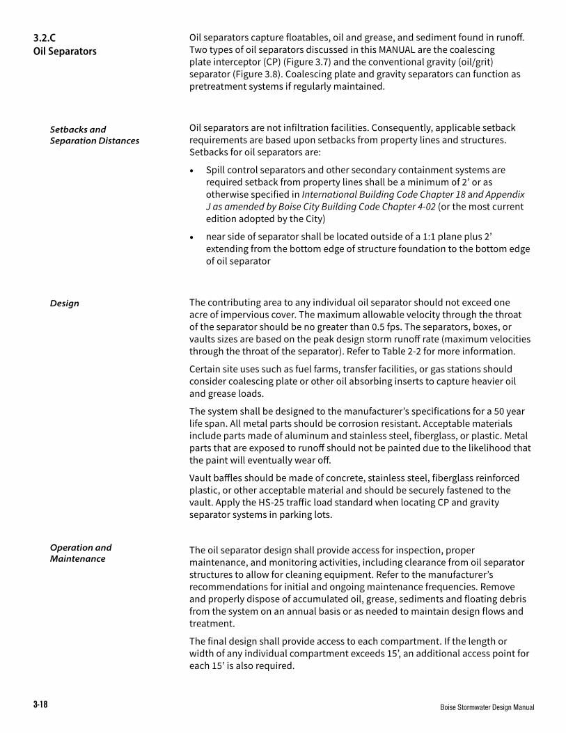
Boise Stormwater Design Manual3-18
Oil separators capture floatables, oil and grease, and sediment found in runoff. Two types of oil separators discussed in this MANUAL are the coalescing plate interceptor (CP) (Figure 3.7) and the conventional gravity (oil/grit) separator (Figure 3.8). Coalescing plate and gravity separators can function as pretreatment systems if regularly maintained.
Oil separators are not infiltration facilities. Consequently, applicable setback requirements are based upon setbacks from property lines and structures. Setbacks for oil separators are:
• Spill control separators and other secondary containment systems are required setback from property lines shall be a minimum of 2’ or as otherwise specified in International Building Code Chapter 18 and Appendix J as amended by Boise City Building Code Chapter 4-02 (or the most current edition adopted by the City)
• near side of separator shall be located outside of a 1:1 plane plus 2’ extending from the bottom edge of structure foundation to the bottom edge of oil separator
The contributing area to any individual oil separator should not exceed one acre of impervious cover. The maximum allowable velocity through the throat of the separator should be no greater than 0.5 fps. The separators, boxes, or vaults sizes are based on the peak design storm runoff rate (maximum velocities through the throat of the separator). Refer to Table 2-2 for more information.
Certain site uses such as fuel farms, transfer facilities, or gas stations should consider coalescing plate or other oil absorbing inserts to capture heavier oil and grease loads.
The system shall be designed to the manufacturer’s specifications for a 50 year life span. All metal parts should be corrosion resistant. Acceptable materials include parts made of aluminum and stainless steel, fiberglass, or plastic. Metal parts that are exposed to runoff should not be painted due to the likelihood that the paint will eventually wear off.
Vault baffles should be made of concrete, stainless steel, fiberglass reinforced plastic, or other acceptable material and should be securely fastened to the vault. Apply the HS-25 traffic load standard when locating CP and gravity separator systems in parking lots.
The oil separator design shall provide access for inspection, proper maintenance, and monitoring activities, including clearance from oil separator structures to allow for cleaning equipment. Refer to the manufacturer’s recommendations for initial and ongoing maintenance frequencies. Remove and properly dispose of accumulated oil, grease, sediments and floating debris from the system on an annual basis or as needed to maintain design flows and treatment.
The final design shall provide access to each compartment. If the length or width of any individual compartment exceeds 15’, an additional access point for each 15’ is also required.
3.2.C Oil Separators
Setbacks and Separation Distances
Design
Operation and Maintenance

Boise Stormwater Design Manual 3-19
A catch basin insert is a device installed underneath a catch basin inlet that treats stormwater through filtration, settling, absorption, adsorption, or a combination of these mechanisms. Catch basin inserts may be required to provide additional pretreatment for off-site discharges to sensitive water bodies or at sites with risk for high pollutant loads.
Because performance varies widely among the different devices, a set of performance criteria will be used for these devices rather than design standards. The evaluation tests assume the use of suitable oil absorbing/adsorbing media. Table 3-1 shows performance criteria for catch basin inserts.
Criteria Evaluation MethodsInsert has ability to treat the water quality design flow for a minimum of 6 weeks under typical conditions.
Subject the system to the maximum flow rate when new, and again after four to six weeks deployment. All flow must pass through the treatment area without short circuiting or bypass
Insert has ability to create a positive seal around grate to prevent low-flow bypass.
Install and observe unit under low-flow conditions. All flow must pass through the treatment area
Media system functions so that its surface does not become blinded shortly after deployment and cause stormwater to bypass media before full use of media is realized.
Inspect media after four to six weeks deployment
Media resists water saturation and maintains oil absorbing properties for a minimum of six weeks.
Examine media after four - six weeks deployment for signs of water saturation and degradation. Media in acceptable conditions should still absorb oil and repel water.
Insert has means of preventing floating oil from escaping the unit.
Inspect the insert for the presences of an under- over weir at the high-flow relief. If this or some comparable device exits, it is assumed that free oils will be retained.
Insert has means of preventing oil-soaked media from escaping the unit
When the insert is new, and again after four to six week deployment, subject it to the peak flow rate and observe whether media escapes.
Insert has ability to pass high flows without causing excessive ponding.
Blind all filtration surfaces with plastic sheeting and subject the insert to the required flow. No ponding round the drain inlet should occur for the 25 year peak rate
Manufacturer provides complete installation maintenance instructions.
Verify that instructions include information on the following: installation, creating an adequate seal, removal (including safety considerations), cleaning and replacement, decant and disposal of liquid waste, media disposal guidance.
Adapted from King County Surface Water Design Manual, 1998
Catch basin inserts shall be located in easily accessible areas for maintenance activities. Drainage plans shall not place inserts in areas with continuous vehicle parking. Consequently, redevelopment projects may have to modify a parking stall in order to provide access to a catch basin insert.
3.2.D Catch Basin Inserts
table 3-1 PerFormanCe Criteria
anD eValuation methoDS For
CatCh baSin inSerts
Setbacks and Separation Distances

2015 Boise Stormwater Design Manual3-20
Depending on the adjacent land use and associated target pollutants, the insert may be fitted with oil-absorbent/adsorbent filter media. If the insert is installed in an existing catch basin, the insert shall be demonstrated to fit properly so that there is a positive seal around the grate to prevent low-flow bypass.
If the insert is installed in a new or redevelopment project, it shall be installed according to the manufacturer’s recommendations. The insert should be installed in the catch basin after the site has been paved or stabilized (for new development) or after completion of construction (for a redevelopment site that is already paved).
Catch basin inserts shall be maintained at a frequency recommended by the manufacturer or when the filter media surface is covered with sediment. Clean accumulated oil, grease, sediments and floating debris from oil/grit separators every two years, unless inspections show that more frequent maintenance is necessary. In addition, the catch basin sump should be inspected for sediment accumulation. Full replacement or renewal of oil absorbent/adsorbent material, if present, shall be part of the required maintenance activities.
Filter media shall be disposed of in accordance with applicable regulations, including Ada County Solid Waste Ordinance (Title 5, Chapter 2) and hazardous waste regulations (40 CFR Parts 260-263, 266, 273, and 279). In most cases, dewatered filter media may be disposed of as solid waste.
Operation and Maintenance
Design

2015 Boise Stormwater Design Manual 3-21
Figure 3.7 CoaleSCing Plate oil SeParator

2015 Boise Stormwater Design Manual3-22
Figure 3.8 oil SeParator

2015 Boise Stormwater Design Manual 3-23
3.2.E Infiltration Facilities
This section contains requirements for facilities that manage stormwater by subsurface disposal through infiltration. Requirements are included for infiltration swales, infiltration basins, and seepage beds.
Infiltration swales (Figure 3.11) are vegetated depressed landscaped areas designed to collect, treat, and infiltrate stormwater runoff. Swales infiltrate stormwater runoff during storm events and protect ground water through natural treatment processes. Swales may include an in-situ sand filter as an aide to long-term system performance, and to reduce maintenance costs.
An infiltration basin (Figure 3.12) impounds water in a surface pond until it infiltrates into the soil. Infiltration basins do not maintain a permanent pool between storm events.
A seepage bed (Figure 3.13) receives runoff in a shallow excavated trench that has been backfilled with stone to form a below-grade reservoir. Seepage beds are typically located beneath landscaped or parking areas. Seepage beds may be preceded or followed by a sand filter or equivalent type of pretreatment as an aide to long-term operation and maintenance.
Onsite dispersed and de-centralized stormwater treatment and disposal systems based on Green Stormwater Infrastructure (GSI) principles are cost effective for our local community because they:
• eliminate the need to build extensive publicly owned regional treatment systems in order to protect receiving waters
• offer viable treatment options for pollutants via sun, vegetation, root systems, soils, or filter sand
• can include attractive landscaping
• promote groundwater recharge
For each infiltration facility, the applicant will be required to submit a written report that includes the general plan submittal requirements (see Chapter 2, General Stormwater Requirements) and the following additional information:
Site characteristics that pertain to the proposed infiltration system (site evaluation information):
• a geotechnical report together with a location map showing the dates and locations of test pits or borings, the exploration logs, and the infiltration test reports
• written opinion of site suitability by a geologist, soil scientist, or engineer
• recommended design infiltration rate
• infiltration test data and results for sites that do not have free draining sand and gravel including test method, measurements, reduction factors, and design infiltration rate for each drainage facility
General Design Criteria

2015 Boise Stormwater Design Manual3-24
Idaho Department of Water Resources (IDWR) has developed criteria to classify a feature as a shallow injection well (SIW) based on their interpretation of Federal and State rules. The State of Idaho uses the Federal definitions for fluid and subsurface fluid distribution system in IDAPA 37.03.03 - Rules for the Construction and Use of Injection Wells. Refer to IDWR for more information.
Figure 3.9 depicts trenches that are not deeper than their longest surface dimension. The first two trenches do not require a SIW Inventory form because they do not use a subsurface fluid system (e.g. perforated pipe).
Figure 3.9 Shallow trenCheS
Figure 3.10 depicts boreholes that are deeper than their largest surface dimension, that may or may not be filled with sand or gravel, and do not use a subsurface fluid distribution system. These types of boreholes would require a SIW Inventory form because they meet the definition of an injection well.
Source: Idaho Department of Water Resources Shallow Injection Well Criteria (Eff. 7/1/2011)
Figure 3.10 DeeP boreholeS
Source: Idaho Department of Water Resources Shallow Injection Well Criteria (Eff. 7/1/2011)

2015 Boise Stormwater Design Manual 3-25
Geotechnical reports are required for sites where an infiltration system is proposed. In general, geotechnical reports are to include enough information in order to address the following site information requirements:
• types of soil and subsurface materials underlying the infiltration facility
• infiltration rates, locations, and test dates at the infiltration facility locations (e.g., generally within 50’ of the facility unless the geotechnical professional provides an opinion that the substrate at the tested/observed location extends to the infiltration facility)
• permeability test method, reduction factor, and permeability of the soil and subsurface materials underlying the infiltration facility
• slope and geometry of the site
• proximity to surface water
• proximity of the seasonal high ground water table beneath the bottom of the infiltration facility
• proximity and classification of bedrock beneath the bottom of the infiltration facility
The infiltration rate shall be measured at a depth equal to the proposed bottom grade of the facility.
The City has identified a series of design, inspection, and maintenance practices that ensure infiltration systems will operate as designed. Moreover, many sites within the Boise area have high infiltration capacities. However, if certain criteria are not met, the City will require bulk water testing in accordance with the General Testing Procedures included in Appendix E of this MANUAL.
The City will require swale tests under the following conditions:
• at sites that do not have well drained sand and gravel dominated soils or basalt with infiltration rates less than 2” per hour as determined by the test per the Stormwater Management Plan Checklist (Figure 2-1)
• where inspections have not been properly scheduled and conducted, or when construction is found to be non-compliant with the design plans and specifications
Additionally, the City will require infiltration tests for swale and basin designs where an in-situ sand filter is not used and:
• the material used to back-fill the swale or basin does not match the design infiltration rate (permeable soil with organic, sandy/loam characteristics, and < 1% clay or passing the #270 sieve-size)
• grass sod is used along the bottom
If a swale test is required, the method and approximate location(s) where the test is to be conducted shall be submitted to the City for review.
In the event that a swale test must be performed, additional inspection and swale testing fees shall be charged to the permit holder and scheduled with the City. Alternatively, either the contractor or contractor’s qualified representative shall perform the testing.
Geotechnical Report
Requirements
Infiltration Swales and Basins Testing and
Performance Evaluation

2015 Boise Stormwater Design Manual3-26
Swale tests must be witnessed and certified by the design engineer or the design engineer’s designated representative.
An acceptable infiltration test is one where all water is infiltrated within the identified test period. For example, where 75% of the test volume is infiltrated within the first 24 hour period and all water is infiltrative within the next 24 hour period (48 hours from the start of the test).
If infiltration tests cannot satisfy the above criteria, the swale must be reconstructed. Prior to reconstruction, the design professional shall complete an investigation to determine the cause of unacceptable in- filtration rate performance. Design shall be modified or alternate construction methods or materials (or both) shall be used in reconstruction of the system. System shall be retested after construction and shall meet minimum performance criteria as identified above. Final occupancy permits, where applicable, will not be granted until the reconstructed swale functions as designed.
For those sites where the infiltration facility does not fully drain within 48 hours, the facility owner shall be considered to be in violation of the ORDINANCE and subject to the penalties contained therein.
Setback and separation distance requirements for infiltration facilities are:
• a minimum of 2’ setback from the property line or as otherwise specified in International Building Code Chapter 18 and Appendix J as amended by Boise City Building Code Chapter 4-02 (or the most current edition adopted by the City) or unless permitted by a specific easement.
• a 100’ separation distance from public wells, private wells, and surface water supplies used as drinking water and a 50’ separation distance from surface water supplies not used as drinking water, excluding drainage and irrigation delivery systems
• current State of Idaho requirements for individual subsurface sewage disposal (IDAPA 58.01.03) require that all “temporary surface water” sources maintain a 50’ horizontal separation distance between septic drain fields and a 25’ horizontal separation distance between septic tanks
• for all infiltration facilities, except seepage beds, a minimum 3‘ vertical separation distance from the bottom of the infiltration facility to the seasonal high ground water table, with a minimum 2’ of soil between the bottom of the infiltration basin and the high ground water table. Soil materials may be either native soils with design percololation rates identified in the geotechnical reports or ASTM C-33 sand if native percolation rates exceed 8”/hr.
• a minimum 5’ vertical separation distance from the bottom of the infiltration facility to bedrock or basalt
• seepage beds shall have a 10’ separation distance from the bottom of the facility to the high ground water table; this separation distance may be reduced to a minimum of 5’ when a sand filter pretreatment system or equivalent is installed to treat the design storm volume.
• 10’ separation from structural foundations unless different setbacks are recommended by the structural foundation engineer
Setbacks and Separation Distances

2015 Boise Stormwater Design Manual 3-27
Open infiltration stormwater facilities (e.g., infiltration swales, infiltration basins, and surface trenches) have the following additional setback requirements:
• perimeter slopes (swale excavation) must be a minimum of 2’ from the property line or as required by the International Building Code Chapter 18 and Appendix J as amended by Boise City Building Code Chapter 4-02, unless permitted by a specific easement
• open infiltration facilities shall be located at a minimum 10’ distance from any structure foundation to protect its integrity and to prevent any intrusion of drainage into or beneath the building.
As stated in Chapter 2, the City requires that the entire post-development water quantity volume be retained on site unless otherwise permitted by the receiving property owner and City. The City infiltration design standards require measures to protect ground water quality (e.g., adequate sand filtration and/or distance to seasonal high water elevation). All infiltration facilities are to fully drain within 48 hours following design storm events.
The bottom of the system shall be constructed at least 12” into free-draining material. Appropriate permeable soil types are those that have an infiltration rate of 0.5” per hour or greater, as initially determined from NRCS Soil Textural Classification and subsequently confirmed by field geotechnical tests (see Section 3.2.E and Appendix E for more information on geotechnical reports). For all infiltration facilities, a minimum field infiltration rate of 0.5” per hour is required. Locations yielding a lower infiltration rate preclude infiltration.
All infiltration systems that are located at sites with a very high infiltration rate (e.g., > 20”/hr) present a risk of short-circuiting (where the stormwater volume flows around the filter). For sites with infiltration rates that are more than 8” per hour, a 12” layer or greater of ASTM C-33, fine grade sand or equivalent is required at the bottom of the facility.
Additionally, for sites with infiltration rates that are more than 8” per hour, the design shall include measures to address the inherent risk of stormwater treatment short-circuiting (Figure 3.13, Sht. 1 of 2). Infiltration facilities must not be used on slopes greater than 20%.
Facility operators should inspect and clean the infiltration facilities when necessary. Generally, infiltration rates of ASTM C-33, fine grade sand, can be up to 20”/hour when initially installed. Over time, as fine sediments accumulate within the facility, the infiltration rate will decrease. When the facility’s infiltration rate approaches the infiltration rate used in the design calculations used to size the facility, the system will require renovation to re-establish an adequate infiltration rate once more. Sediments shall be removed and disposed of properly. O&M plans for infiltration facilities should include limitations for fertilizer and pesticide use in order to reduce the discharge of these materials into ground water.
Design
Operation and Maintenance

2015 Boise Stormwater Design Manual3-28
An infiltration swale (Figure 3.11) is a depressed landscaped area designed to collect, treat, and infiltrate stormwater runoff. Infiltration swales can either have a continuous cover of vegetation or include a sand infiltration window along the swale bottom.
Setbacks and separation distances for infiltration swales are the same as those listed in Section 3.2.E (for all infiltration facilities).
Design requirements specific for infiltration swales include:
• Swale bottom slopes shall be flat or sloped gently to a low point. Recommended maximum grade for slope swales is 1% to 2%.
• Permeable soil (e.g., with an infiltration rate of 0.5” or more per hour) is to be installed to encourage infiltration along the swale bottom. Bioretention Soil Mix (BSM) is recommended. See Appendix C for BSM specifications.
• If an underdrain is used at a site that has an infiltration rate greater than 8” per hour, then a 12” sand layer is required either along or below the underdrain. The design must address potential short circuiting to ensure the storm volume infiltrates through the sand.
• Curb cut pavement shall be installed at a maximum height of 6” above the swale if curb cuts will be used to introduce flow to the swale. Curb cuts shall be between 12” and 36” wide.
• A flow spreading device placed at the swale inlet should be considered. Appropriate devices include shallow weirs, stilling basins, and perforated pipes. Provide a sediment clean-out area.
• Energy dissipation shall be provided at the inlet. Appropriate means are stilling basins and rip rap pads. If rip rap is used, it should be sized for the expected runoff velocity.
• An in-situ sand drainage window may be included in the swale design (Figure 3.11). The sand window is to have a minimum 18” depth ASTM C-33 sand located above the seasonal high ground water elevation. The sand layer could have geotextile fabric along the side walls. Drain rock may also be located at the bottom in order to reduce the risk of wicking. The surface area of swale drainage windows is not be more than 20% of the swale bottom. Sand windows are required to have large cobbles or 2” drain rock placed over the top in order to prevent wind and water erosion.
• The swale side slopes shall be no more than 3:1.
• The swale shall be covered with grass or a mixture of grass and other vegetation suitable for the swale environment. Uniformly fine, close-growing, water-tolerant grasses should be used. The side slopes above the swale treatment area should be vegetated to prevent erosion. Additional grass or non-aggressive ground covers are appropriate.
• If installed, the swale under drain shall be constructed using clean 2” drain rock. The rock shall be wrapped in geotextile filter fabric, with a weight of greater than 4 oz. /yd2. The under drain will be a minimum depth of 12”. Based on the site conditions, drain rock is an optional addition to the swale design in order to provide additional storage volume.
3.2.E.2 Infiltration Swales
Setbacks and Separation Distances
Design

2015 Boise Stormwater Design Manual 3-29
Figure 3.11 depicts optimal swale design elements. Please refer to the MANUAL text for minimum design requirements. Optional design improvements include specifying the depth of the ASTM C-33 fire grade sand into free draining material, placing drain rock at the swale bottom surface elevation, providing a cedar border around the in-situ sand filter, and increasing the in-situ sand filter depth from the minimum 18” required to 24.”
Swales shall not be used until the vegetation is established. Barrier shrubs, such as barberry, planted around the swale should be considered when there is a possibility that the public could damage the swale or hinder its function.
Avoid using bark, floatable mulch, fertilizers after plant establishment, and pesticides in swale bottoms or sides. These materials tend to run off the planted area and into the swales reducing its treatment effectiveness.
Following the establishment of swale vegetation, irrigation rates and water volume applied to the swale shall be monitored. Monitoring, consisting of periodic visual inspections shall consider needs of plant materials as they are maturing and will likely result in adjustments to the amount of water being applied to swale vegetation.
Standing water in the bottom of a swale resulting from over watering is to be avoided. The designer should consider providing separate sprinkler irrigation zones for swale bottoms and swale sides. The O&M plan shall identify the appropriate plant and irrigation management steps to ensure swale vegetation growth and vigor.
In-situ sand windows slowly trap fine materials as part of the water quality treatment. Moreover, the accumulation of these fine materials may limit infiltration to unacceptable levels as the sand becomes clogged. Therefore, O&M plans for in-situ sand windows are to specify that these and filter’s ability to infiltrate should be checked on an annual or semi-annual basis and are to be renovated when the infiltration rate drops below the minimum design rate.
O&M plans for all infiltration facilities should include limitations for fertilizer and pesticide use in order to reduce the discharge of these materials into ground water.
Aeration of areas with sediment deposits may retain swale function. Sediment removal should include consideration of historical operating conditions of the swale and the potential for hazardous materials to be present in sediments. The City Operation and Maintenance Resource Guide provides sediment testing and proper disposal protocols. Visit www.partnersforcleanwater.org for more information.
Sediment deposition in vegetated swales should be removed if grass growth is being inhibited for more than 10% of the swale area or if the sediment is blocking the entrance or even spread of water into the swale. Sand swales are to apply similar operation and maintenance as required for sand filters (see Section 3.2.A). Facility operators should anticipate annual sediment removal and/or spot reseeding. Aeration of sediment containing areas may also be required to retain swale function. If sediment is removed or the swale is reconstructed, the swale should be re-graded and reconstructed to meet the original design conditions.
Landscaping
Operation and Maintenance

2015 Boise Stormwater Design Manual3-30
An infiltration basin (Figure 3.12) impounds water in a surface pond until it infiltrates into the soil. Infiltration basins do not maintain a permanent pool between storm events and should drain within 48 hours after a design storm event. An infiltration basin is suitable in residential and commercial developments. However, infiltration basins should not be placed in locations where the basin could cause flooding to downstream properties or in natural drainages such that the basin would restrict inflows to the point of causing upstream flooding.
Setbacks and separation distances for infiltration basins are the same as those listed in Section 3.2.E. (for all infiltration facilities).
In determining the size of the basin, the critical parameters are the storage capacity and the infiltration rate of the basin.
Infiltration basins shall be constructed in appropriate soil types. Bioretention Soil Mix (BSM) is recommended for infiltration basins. See Appendix C for BSM specifications. Infiltration basins should be excavated in a manner that will minimize disturbance and compaction of the basin. The basin bottom should be flat to maximize infiltration. Infiltration basins should not be constructed where the contributing area has high erosion rates, on slopes greater than 15%, or within fill soils. If inlet and outlet channels are present, these must be stabilized.
Each infiltration basin shall have additional pretreatment. One of the following techniques can be used:
• a grass channel
• a grass filter strip
• a bottom sand layer
• an upper filter fabric with 6” sand layer
• a vegetated basin with deep-rooted turf
• sand and grease trap
Infiltration basins should be inspected at least twice a year. Recommended inspection times are early spring (March or April) and late fall (September or October). Infiltration basins should also be inspected after each major storm event.
Inspections should note the status of basin vegetation, evidence of standing water in the basin, accumulated sediment in the bottom of the basin, unusual or unpleasant odors, and function of inlet and outlet structures, if present. Embankments should also be checked for erosion. If any of these conditions are noted, basin maintenance will likely be required.
For eroded or barren areas, reseed or replant. Vegetation selection is important in choosing plant material that is compatible with on site moisture and soil conditions.
If standing water is present in the basin longer than 48 hours after a storm event, it is likely that surface basin soils have clogged. Removal, replacement, or reconditioning (e.g., aeration or plowing) of clogged soils may be required.
3.2.E.3 Infiltration Basin
Setbacks and Separation Distances
Design
Operation and Maintenance

2015 Boise Stormwater Design Manual 3-31
Over time, sediments entrained in stormwater will accumulate in the bottom of the basin. Eventually the sediment will limit the permeability of the basin bottom. Facility operators must remove accumulated sediment from the basin if sediment levels reach the depth identified in the basin’s O&M plan or if accumulated sediment results in inadequate infiltration rates.
The presence of unusual or unpleasant odors is indicative of inappropriate materials that have been carried into the basin by stormwater flows or are the result of decaying vegetation or other non-stormwater related organic matter. Locate and remove the source of the odor.
A seepage bed (Figure 3.13) receives runoff in a shallow excavated trench that has been backfilled with stone to form a below-grade reservoir. They are typically located beneath landscaped or parking areas and shall drain within 48 hours after a storm event.
Seepage beds are prohibited in the following situations:
• where contamination exists in soil and/or ground water
• where there is fill material and the possibility of creating an unstable grade and potential for movement at the interface between the fill and in-situ soils
Additional pretreatment and spill control for seepage beds located at land uses that have a potential for high pollutant loads may be required. See Section 2.5.C for additional information.
Boise City may prohibit seepage bed use depending on the site’s vadose zone characteristics and depth to groundwater. Final determination of seepage bed use is determined by evaluating the natural, unaltered characteristics of the proposed location for the system.
Setbacks and separation distances for seepage beds are the same as those listed in Section 3.2.E (for all infiltration facilities). Additional setbacks and separations distances required for seepage beds include:
• Seepage beds must be separated a minimum of 10’ from ground water (vertical distance from bottom of facility to seasonal high ground water level). This separation distance may be reduced to a minimum of 5’ when a sand filter pretreatment system or equivalent is installed to treat the design storm volume.
• A test boring shall be drilled to a sufficient depth to verify a 10’ (or 5’ when a sand filter pretreatment system or equivalent is used) separation distance between the proposed bottom of the facility and seasonal high ground water table.
• Each seepage bed facility shall have at least one test boring, unless prior approval is obtained from the Public Works Department.
• Seepage beds must be separated 10’ from structure foundations. A structural engineer may approve seepage bed setbacks from structures that are less than 10’.
• Seepage beds must be set back a minimum of 20’ from structures with basements unless a different or lesser separation distance is allowed by a geotechnical and structural engineer.
3.2.E.4 Seepage Beds
Setbacks and Separation Distances

2015 Boise Stormwater Design Manual3-32
Design requirements specific for seepage beds include the following:
• Seepage beds should be designed to provide a direct method for removal of contaminants and sediments before direct discharge into the vadose zone.
• A stone aggregate of clean, washed drain rock, 1.5” - 2” in diameter should be used to provide the required void ratio of 30% - 40%. A different size aggregate may be used if the required void ratio (e.g., 30% – 40%) is certified by an independent testing laboratory.
• The bottom of the seepage bed shall be covered with an 18” layer of ASTM C-33 sand (or equivalent) in conjunction with a reduced separation distance to the seasonal high ground water.
• The seepage bed aggregate must be lined on the sides by an appropriate geotextile fabric. If the trench is an open trench, it should also be lined at the top and the top. The fabric layer should be located 1’ below the surface to prevent surface sediment from passing through into the stone aggregate. At the discretion of the designer, filter fabric may be placed on the bottom of the trench and should have: a minimum weight of at least 4 oz. /yd2, a filtration rate of at least 0.08”/second, and an equivalent opening size of 30 for non-woven fabric.
• Seepage beds located at sites with infiltration rates greater than 8” per hour have the potential for stormwater treatment bypass. The seepage bed facilities located at these sites are required to have either upfront pretreatment equivalent to sand filtration or the sides of the seepage bed are to be wrapped with impermeable fabric or with a permeable barrier equivalent to sand filtration.
• Seepage beds must have observation wells. Wells shall be placed every 2000 ft2 unless otherwise recommended in the geotechnical report. The observation well should be a perforated schedule 40 PVC pipe, 4” - 6” in diameter, extending to the bottom of the bed where it is connected to a footplate. The observation well should be capped and locked to prevent vandalism or tampering (see Figure 3.13).
• Seepage beds should be located for easy access by maintenance equipment. If located in a landscaped area, the seepage bed should be covered with native soils and planted in grass or, if the seepage bed is an open trench, it must be covered with stone aggregate and protected from sediment build-up with a grass buffer strip 20’-25’ wide on all sides of the bed.
When ponding occurs at the ground surface or in the bed, corrective maintenance is required. Ponding indicates that the seepage bed or the distribution pipe is clogged. A field investigation may be warranted to determine the cause of seepage bed clogging. The owner is required to repair, replace, or reconstruct the seepage bed if it fails to operate as designed. A system fails to operate as designed when water is standing 48 hours or longer following the design storm, with risk of off site discharge. The maintenance and operation schedule for an infiltration system shall include such a provision when system failure occurs. The owner is required to notify City if the owner plans to close or replace the infiltration system.
Design
Operation and Maintenance

2015 Boise Stormwater Design Manual 3-33
Figure 3.11 inFiltration Swale
NOTE: Consider using Bioretention Soil Mix (BSM) for filtration treatment and growth media. BSM specifications are found in Appendix C.

2015 Boise Stormwater Design Manual3-34
Figure 3.12 inFiltration baSin
WITH VEGETATION
NOTE: Consider using Bioretention Soil Mix (BSM) for filtration treatment and growth media. BSM specifications are found in Appendix C.

2015 Boise Stormwater Design Manual 3-35
Figure 3.13 SeePage beD (Sheet 1 oF 2)

2015 Boise Stormwater Design Manual3-36
Figure 3.13 SeePage beD (Sheet 2 oF 2)

2015 Boise Stormwater Design Manual 3-37
Ponds are stormwater facilities designed to retain or detain stormwater runoff. They provide water quantity storage, water quality treatment for stormwater runoff, and may be used to provide peak flow attenuation. The different ponds permitted in Boise include a dry detention pond, a wet extended detention pond, and an evaporation pond.
Detention ponds collect and temporarily hold surface and stormwater runoff from a site and release it at a slower rate than it is collected. They are traditionally used to attenuate peak flows, to mitigate downstream impacts, and to alleviate flooding problems. Detention ponds are suitable in residential, commercial, and industrial sites.
A dry detention pond is a pond designed to collect and temporarily hold surface and stormwater runoff from a site and release it at a slower rate than it is collected. Dry detention ponds do not maintain permanent pools. A wet extended detention pond is a pond designed to treat and release surface and stormwater runoff from a site, while maintaining a permanent pool. An evaporation pond is a pond designed to collect and hold surface and stormwater runoff from a site until it evaporates.
Ponds may be used at sites where a receiving body or structure can accept pond discharges. Ponds designed to meet on-site detention requirements shall not be located in regulatory floodplains. Sites should be evaluated for soils, depth to bedrock, and depth to water table. Requirements will depend on pond type.
Property line setbacks shall be as specified in the International Building Code Chapter 18 and Appendix J as amended by Boise City Building Code Chapter 4-02 (or the most current edition adopted by the City).
Additional requirements include:
• side slopes of ponds shall not be located closer than 2’ from property lines
• a 100’ minimum separation from public and private wells
• a 100’ separation distance from surface water supplies used as drinking water and a 50’ separation distance from surface water supplies not used as drinking water, excluding drainage and irrigation delivery systems
• a 10’ separation from structural foundations
The system should be designed for at least a 50 year life. The design of any pond requires consideration of several factors:
• basin size
• minimum free board
• maximum allowable depth of temporary ponding
• recurrence interval of the storm being considered
• storm duration
• timing of the inflow
• allowable outflow rate
• residency of water (time water remains in the facility)
3.2.F Ponds
General Design Criteria
Setbacks and Separation Distances
Design

2015 Boise Stormwater Design Manual3-38
Pond performance is subject to City review and approval based upon the submitted design calculations. See the individual pond designs for specific performance evaluation requirements.
The following design requirements apply to all ponds permitted by the City:
• maximum outflow rate shall not be more than the pre-development rate of runoff for each storm return interval (2, 5, 10, 50, and 100 year, where applicable) events
• the receiving system must be shown to be capable of accommodating the pre-development flow
• outlet pipes shall be at least 12” in diameter. If riser pipes are used, they shall be 1.5 times the cross sectional area of the outfall pipe
• trash racks or anti-vortex devices shall be installed
• all pipe joints are to be watertight
• anti-seep cutoff walls that are at least 8” thick or other seepage control methods are to be installed around outlet pipes
• the channel immediately below the pond outfall shall be protected against erosion and shall transition to natural drainage conditions in the shortest distance possible
Once the design volume and TSS removal efficiencies are calculated, the resulting pond size shall be increased an additional 15% to accommodate long-term sediment storage. Additionally, a fixed vertical sediment depth marker shall be installed to measure sediment accumulation.
Vegetative Buffers
Vegetative buffer strips shall be established around the perimeter of the pond for erosion control and additional sediment and nutrient removal. Buffer strips should include all areas between the normal pond water surface elevation to the top of the pond embankment.
Side Slope Safety Requirements
Take all practical safety precautions. Side slopes should not exceed 4:1 (3:1, if the pond will normally remain dry). Fencing may be required on slopes steeper than 4:1 and shall be constructed using the following criteria: chain link material, 6’ high with an 11 gauge, 2” mesh or other similar construction. The fence construction shall be strong enough to prohibit public access.
Freeboard Requirements
Open ponds shall be designed with freeboard above the maximum design water elevation in accordance with the following criteria:
Water Depth Freeboard0-12” 6”
12-36” 12”>36” 18”

2015 Boise Stormwater Design Manual 3-39
Emergency Spillway Requirements
Emergency spillways are required on all ponds. The spillway shall be sized to safely pass a minimum 100 year storm event. If the facility is considered a dam by IDWR, additional requirements may apply. The emergency spillway should be protected against erosion.
The emergency spillway elevation shall be set at the maximum water surface level. Freeboard height shall be set above the depth of flow in the spillway.
Dams and Embankments
A pond may be categorized as a dam if the vertical distance between the high water elevation and the downstream flow line exceeds 10’ or the pond impounds more than 50 acre-feet of water.
The minimum top widths of all dams and embankments are:
Height Top Width0’-5’ 10’
5’-10’ 12’10’-15 14’
The design top elevation of all dams and embankments, after all settlement has taken place, shall exceed the maximum water surface elevation in the pond. The design top elevation shall be the maximum routed hydrograph water surface elevation plus the required freeboard height. The design height of the dam or embankment is defined as the vertical distance from the top down to the bottom of the deepest cut. The height shall be increased by the amount needed to assure that the design will be adequate after settling. Where necessary, the engineer shall require consolidation tests of the undisturbed foundation soil to more accurately determine the necessary increase.
A soils investigation is required on all ponds. At a minimum, it shall include information along the centerline of the proposed dam at the emergency spillway location and in the planned borrow area. The soils investigation should include recommendations on cutoff trenches, benching, compaction, and any other special design requirements.
Maximum side slopes for all dams and embankments are 3:1 on the upstream or impoundment side and 2:1 on the downstream side, or as approved by IDWR.
All earth fill should be free from brush, roots, and organic material that may decompose.
Cutoff walls are to be constructed along the dam or embankment centerline. Walls should be constructed of impervious soil or concrete, piling, plastic sheeting or other material as approved by IDWR.
The fill material in all earth dams and embankments shall be compacted. The minimum field compaction shall be 95% of the maximum laboratory density as determined by AASHTO T-99 Method A. Certification of compaction shall be provided by an independent testing laboratory and reviewed and approved by the design engineer.

2015 Boise Stormwater Design Manual3-40
Ponds normally do not require a great deal of maintenance. However, facility operators should inspect ponds at least once a year and following any significant storm event. Pond components requiring inspection include:
• embankments
• side slopes
• vegetative cover on embankments, perimeter, and inside the pond
• perimeter fencing
• sediment deposition
• inlet and outlet structures
• emergency spillways
Facility operators should check pond embankments for erosion, holes excavated by rodents or other animals, and vegetative cover both above and at bank levels. The pond bottom should be checked for sediment deposition, deposition of noxious materials, or other debris.
Accumulated sediments shall be measured annually by examining the pond depth. Accumulated sediments must be removed when they exceed 15% of the total pond volume.
Inlet structures should be checked for erosion, sediment deposition, channel scour, and plugging. Outlet structures should be inspected for clogging or plugging, short-circuiting of outlet flows, and erosion at the inlet or outlet side of the structure.
Facility operators should note the presence of objectionable or noxious odors and remedy any superficial, structural, aesthetic, or facility capacity shortcomings.
Detention ponds collect and temporarily hold surface and stormwater runoff from a site and release it at a slower rate than it is collected. They are traditionally used to attenuate peak flows, to mitigate downstream impacts, and to alleviate flooding problems. Detention ponds are suitable in residential, commercial, and industrial sites.
Setbacks and separation distances for dry detention ponds are the same as those listed in Section 3.2.F (e.g., for all pond facilities).
Dry detention ponds can be any shape as long as they prevent short circuiting of pond inflows and have sufficient capacity to meet general design and treatment requirements. Calculations for the pond size and TSS removal rates are to be submitted with the drainage design plans for City review and permit approval.
The ability for a dry detention pond to remove TSS is evaluated based on the time of retention (flow path and volume) for representative sediment settling velocities.
The size of a dry detention pond is determined by developing an inflow hydrograph, a depth-storage relationship, and a depth-outflow relationship. The
Operation and Maintenance
3.2.F.2 Dry Detention Ponds
Setbacks and Separation Distances
Design

2015 Boise Stormwater Design Manual 3-41
inflow, storage, and outflow relationships should be based on a storm duration that identifies a peak detention pond volume for the storm interval required.
At a minimum, the pond volume shall be equal to the difference between pre- and post-development storm volumes at peak flow rates. The outlet design shall incorporate a multi-stage riser that will allow water to be drained over an extended period meeting the above requirements for volume retention. The outlet shall be designed to mimic pre-development flow rates for 2, 5, 10, 50, and 100-year storms. The outlet structure shall be designed to prevent clogging and plugging.
Dry detention ponds shall be excavated in a manner that will minimize disturbance and compaction of the pond. Sediment measuring devices shall be installed at opposite ends of the bottom of the basin or sediment trap to measure sediment accumulation.
Ponds shall be designed to contain the computed storage volume plus 15% of the design storage volume to accommodate sediment deposition.
The inlet shall be protected against erosion or scour. Rip rap or other material may be required at the inlet to provide for energy dissipation and erosion protection.
Dry detention ponds shall be stabilized with vegetation to control dust and improve pond aesthetics. A landscaping plan for a dry extended detention pond shall be submitted to indicate how aquatic and terrestrial areas will be stabilized with appropriate vegetation. Bottom and banks of all dry extended detention ponds shall be stabilized with gravel, rock, vegetation, or other acceptable material to control dust and prevent erosion.
Operation and maintenance guidelines for dry detention pond are the same as those listed in Section 3.2.F.
A wet extended detention pond is a constructed pond designed to detain a volume of water to allow for the settling of particles and associated pollutants. This type of pond can also be utilized for flood control by including additional temporary storage for peak flows. A wet extended detention pond incorporates a permanent pool and an extended detention area above the permanent pool level.
A wet extended detention pond is suitable in residential, commercial, and industrial sites and is appropriate in areas where nutrient loadings are expected to be high.
Setbacks and separation distances for dry detention ponds are the same as those listed in Section 3.2.F (e.g., for all pond facilities).
Wet extended detention ponds shall have sufficient capacity to meet general design and water quality treatment requirements. Calculations for the pond size and TSS removal rates are to be submitted with the drainage design plans for City review.
Operation and Maintenance
3.2.F.3 Wet Extended
Detention Pond
Setbacks and Separation Distances
Design

2015 Boise Stormwater Design Manual3-42
The ability for a wet extended detention pond to remove TSS is based on the time of retention (flow path and discharge volume), during both the quiescent and non-quiescent settling periods for representative sediment settling velocities. Representative TSS size class distributions and settling velocities during both quiescent and non-quiescent periods are recommended.
The size of a wet extended detention pond for peak discharge management is a function of the required time of retention, an inflow hydrograph, a depth-storage relationship, and a depth-outflow relationship. The inflow, storage, and outflow relationships should be based on a storm duration that identifies a peak detention pond volume for the storm interval required.
Wet extended detention ponds shall be designed for a sufficient detention time (for TSS removal) and to limit peak flow rates to pre-development rates, unless otherwise permitted. Generally, basins with lower velocities and longer retention times provide better removal efficiencies.
The pond’s permanent pool depth shall not exceed 12’. The length from inlet to outlet should be as far apart as possible, with the length to width ratio approximately 3:1. Side slopes of wet extended detention ponds should be 4:1.
The critical parameters in determining the size of the basin are the storage capacity and the maximum rate of runoff released from the basin. In general, the design shall provide an average of 48 - 72 hours detention time, depending on the TSS removal efficiencies. The minimum detention time for very small basins should be at least six hours
Wet extended detention ponds may include an optional sediment fore- bay or equivalent upstream pretreatment. If installed, forebays shall be separate cells formed by acceptable barriers. A weir flow structure or physical separation with pipes may be utilized. If a rock or an earthen berm is constructed, it shall have a minimum top width of 4’ and side slopes no steeper than 3:1 to provide separation from the permanent pool. A drainpipe should be included in the forebay to dewater the pool area for maintenance purposes. Minimum forebay size shall be equal to 15% of the water quality treatment volume, with an optimal volume equal to 25%. Forebay volume shall be in addition to permanent pool volume. A fixed vertical sediment depth marker should be installed in the forebay to measure sediment accumulation.
Outlets of wet extended detention ponds are required to pass a flow rate necessary for extended quantity attenuation and TSS removal efficiencies. The outlet design shall incorporate a multi-stage riser that will allow water to drain over a period that allows the peak outflow to stay at pre-development rates, while providing for TSS removal.
Two benches, a “safety bench” and an “aquatic bench,” shall surround the perimeter of all wet extension ponds (where the pools are at least 4’ deep) (Figure 3.14). The combined minimum width of both benches shall be 15’. A safety bench is a bench that extends landward from the normal water level edge to the toe of the pond side slope. The maximum slope of safety benches shall be 12%. An aquatic bench is a bench that extends from the normal shoreline. The maximum water depth over aquatic benches is 18” below the normal surface elevation of the pool. Additionally, the pond slope between the top of the bank and aquatic benches shall not exceed 2:1.

2015 Boise Stormwater Design Manual 3-43
A landscaping plan for a wet extended detention pond shall be submitted to indicate how aquatic and terrestrial areas will be stabilized with appropriate vegetation. Whenever possible, wetland plants should be used in a pond design, either along the aquatic bench or within shallow areas of the pool. Bottom and banks of all wet extended detention ponds shall be stabilized with gravel, rock, vegetation, or other acceptable material to control dust and prevent erosion.
Operation and maintenance guidelines for wet extended detention pond are the same as those listed in Section 3.2.F (for all ponds). Additional or more specific items requiring maintenance and inspection include sediment forebays, forebay inlet and outlet structures, and pond safety benches.
Evaporation ponds are retention ponds that provide water quantity and water quality control. It is a constructed pond designed to store stormwater runoff and release it through evaporation. The pond should be designed to be dry for at least one month each year.
An evaporation pond is suitable in commercial and industrial sites. It is appropriate in areas where soil types do not allow infiltration (shallow bedrock, heavy clay soils, etc.)
Setbacks and separation distances for evaporation ponds are the same as those listed in Section 3.2.F (for all ponds).
An evaporation pond shall be sized using the following criteria. Two steps are used in calculating the appropriate size for evaporation ponds. The first step is to calculate a month-to-month mass balance of runoff inflow and runoff evaporation:
Inflow = (C)(Precipitation) (Area)
where C = runoff coefficient
Evaporation = (monthly evaporation rate)*(pond surface area)
The extent of runoff areas and assumed pond sizes determine the inflow and evaporation volumes. The monthly differences between inflow and evaporation are calculated over a one year period. One month should show a negative
Figure 3.14 SaFety anD
aquatiC benCh
3.2.F.4 Evaporation Pond
Setbacks and Separation Distances
Design
Operation and Maintenance
12*
* Maximum

2015 Boise Stormwater Design Manual3-44
volume to indicate a dry pond condition. This process will also identify the month when the pond will reach maximum volume.
The second step is to calculate additional pond storage. This step calculates the additional storage needed if the pond is subjected to a major storm during the month that the pond is at maximum volume. Stormwater runoff from the maximum 24 hour storm of record should be determined for the month when the pond is at maximum capacity.
The final pond size is calculated by adding the maximum monthly pond storage (from step #1) to the 24 hour storm of record runoff (from step #2) plus and additional 15%. This additional 15% allows for sedimentation and debris storage.
Bottom and side slopes of all evaporation ponds shall be stabilized with vegetation, gravel, rock, or other acceptable material to control dust and prevent erosion.
Designs of evaporation ponds are to take all practical safety precautions. For example, side slopes of evaporation ponds are not to exceed 3:1 slope.
Facility operators should inspect evaporation ponds at least once per year, preferably in the month of September or October when the pond should be dry, and after each major storm event to check for leakage or overflow. Facility operators can easily maintain the function of an evaporation pond by keeping the pond bottom at an elevation and grade that allows stormwater to spread evenly. This maximizes the pond surface area and resultant evaporation capacity.
In order to maintain the pond’s evaporation capacity, the pond bottom may need to be graded at periodic intervals to remove or spread sediments or vegetation that block the passage of water. Facility operators need to inspect other evaporation pond elements as well such as inlet structures and emergency outlets. Any erosion or channel irregularities at these locations should be repaired.
Operation and Maintenance

2015 Boise Stormwater Design Manual 3-45
Figure 3.15 Dry Detention PonD

2015 Boise Stormwater Design Manual3-46
Figure 3.16 wet extenDeD Detention PonD

2015 Boise Stormwater Design Manual 3-47
Figure 3.17 eVaPoration PonD

2015 Boise Stormwater Design Manual3-48
3.2.G Permeable Interlocking Concrete Pavers (PICP)
Permeable Interlocking Concrete Pavements (PICP) provide an alternative to conventional pavement systems (concrete and asphalt) that permit stormwater to infiltrate through crushed rock particles between precast concrete pavers for temporary storage, infiltration into subsurface soils and/or discharge to another location once stormwater passes through the pavement structure.
PICP consist of high strength concrete blocks separated by gaps or joints between blocks. The joints (typically 5% to 15% of the paver surface) are filled with permeable material that serves as the surficial infiltrative surface for this type of system. Stormwater retention or detention storage and infiltration surfaces are located below the blocks.
Concrete Block Pavers
Pavers shall conform to ASTM C-936 and shall be designed to allow joint spaces between blocks of 5% to 15 % of the total pavement surface.
Subgrade
PICP subgrade shall be tested and approved by a qualified Geotechnical Engineer. Properties and conditions to be evaluated include but are not limited to:
a. soil classification as per ASTM D-2487
b. soil subgrade strength
c. infiltration rate (permeability testing as per ASTM D-3385 or other test method approved by geotechnical engineer)
d. compaction or scarification of subgrade (if required)
Aggregates
• PICP aggregate shall be crushed with 90% fractured faces and a minimum Los Angelos Abrasion factor of less than 40 per ASTM C-131 and C-535.
• Gap aggregate shall conform to ASTM sizes No. 8, 89 or 9 stone.
• Open graded bedding course (2” maximum thickness) shall conform to ASTM No. 8 stone.
• Open graded base reservoir (4” minimum thickness) shall conform to ASTM No. 57 stone (1 - 1.5” crushed stone).
• Open graded sub-base reservoir shall conform to ASTM No. 2, 3, or 4 stone (2 -3”).
General
• Use of PICP is not appropriate for use where hazardous materials may be stored or spilled.
• For design purposes, PICP surface area is 100% permeable. Design infiltration rate is ten inches per hour per square foot of paver area.
• Minimum vertical separation distance between bottom of sub-base reservoir and seasonal high groundwater level is two feet. Geotechnical engineer shall provide opinion on seasonal high groundwater elevation.
• PICP surfaces shall be set back a minimum of 10’ from building foundations unless lesser setbacks are allowed recommended by the foundation engineer.
Material Specifications
Design Criteria

2015 Boise Stormwater Design Manual 3-49
• PICP should not be used if located next to ground slopes in excess of 20% without a vegetative buffer between the slope and PICP surface).
• PICP pavement section design shall be provided by a qualified geotechnical or civil engineer.
• Permeability of subgrade soils shall be determined by a qualified geotechnical engineer. Recommended subgrade infiltration rate is 50% of percolation rate determined by the geotechnical engineer.
• PICP section design will be governed by the deepest section required for either structural performance or stormwater capacity.
• Structural design method shall be in conformance to the AASHTO flexible Pavement design method or ASCE Standard 58-10 / Structural Design of Interlocking Concrete Pavement for Municipal Streets and Roadways.
• For design purposes, PICP Pollutant removal rate for total suspended solids (TSS) is 80% in systems that use offsite discharges.
• In some instances, a sand filter may be required below the PICP section. Situations where a sand filter is required will be made on a case by case basis depending on site conditions and or intended property use.
• Void ratio for base aggregates is 0.4 (40% void space). For design purposes, only the base and sub-base courses can be used for storage volume calculations.
• Aggregate depth shall be determined based on the assumption that no infiltration occurs during the first hour of the design storm.
• For the design storm event, the maximum subgrade surface drainage time shall not exceed 48 hours.
• The designer shall consider manufacturer requirements, product standards, and industry guidelines to ensure lasting effectiveness of PICP systems.
• The surface of the permeable pavement shall have a slope of less than or equal to 6% (except where Americans with Disability (ADA) requirements apply). The surface of the soil subgrade shall have a slope of less than or equal to 0.5%. Terraces and baffles may be installed to achieve flat subgrades under sloping pavement surfaces.
• Permeable pavement systems designed for infiltration shall treat the design storm. Permeable pavement systems designed for detention shall be designed to treat the water quality storm and provide safe conveyance for storms of larger magnitude. Offsite discharge requires acceptance by the stormwater receiving entity.
• Permeable pavement may be designed to receive runoff from adjacent built upon areas such as roofs and conventional pavement (if the soils under the permeable pavement have adequate capacity to infiltrate the additional runoff). The design shall provide storage for the entire runoff volume. In addition, there shall be a well-designed system to convey the runoff from the adjacent built upon areas to the permeable pavement. Maximum recommended run on ratios (from adjacent impermeable surfaces to PICP surfaces) are:
5:1 for roof tops and sidewalks
2:1 to 3:1 for parking lots and private streets

2015 Boise Stormwater Design Manual3-50
• Based upon site conditions and the size of the PICP facility, run-on rates smaller or larger than those listed above may be used by the design professional, if approved by the City.
• When rooftop, sidewalk, and parking areas are all directed to PICP, the maximum recommended run on ratio for all combined areas is 6:1.
• Runoff from adjoining pervious areas, such as grassed slopes and landscaping shall be prevented by grading the landscape away from the permeable pavement. Filter strips designed to remove or trap debris and sediment prior to discharge to permeable pavement may be allowed on a case-by-case basis.
• Runoff from impervious surfaces shall be discharged to the PICP surface by sheet flow
• Runoff from concentrated flow, such as roof drains, must be discharged onto the top of the PICP surface. If possible, run on flows shall be dispersed (sheet flow condition) prior to discharge to the PICP surface. Stormwater discharge directly into the PICP base materials is not permitted.
• Permeable pavement shall not be installed until the upslope and adjoining areas are stabilized. After installations, barriers shall be installed to prevent construction traffic from driving on the pavement.
• The soil subgrade for the permeable pavement shall be graded when dry. The aggregate base and permeable surface course shall be completed as quickly as possible to reduce risk of soil subgrade compaction.
• Permeable pavement may be placed on fill material as long as the material is at least as permeable as the in-situ soil after it is placed and prepared. Design shall be based upon the most restrictive soil. Fill materials shall be inspected and approved by a geotechnical engineer prior to and during material placement.
• An ASTM C-33 sand layer (minimum depth 1’) is required below the structural section where subgrade infiltration rates exceed eight inches per hour.
• A minimum of one observation well shall be provided at the low point in the system unless the subgrade is terraced. In that case, there shall be one well for each terrace.
• Edge restraints shall be provided around the perimeter of permeable interlocking grid pavers as well as anywhere PICP is adjacent to conventional asphalt. Edge restraints shall consist of concrete curbing or a ribbon curb having a minimum width of one foot and a minimum depth of eight inches.
• PICP shall be maintained as specified in an approved Operation and Maintenance (O&M) Manual.
• PICP systems shall be installed by a contractor that has an Interlocking Concrete Pavement Institute (ICPI) Permeable Interlocking Concrete Paver
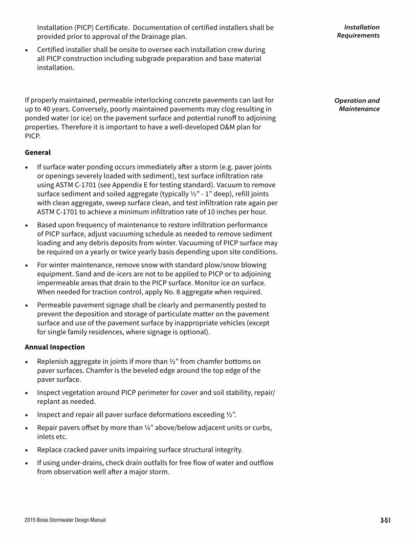
2015 Boise Stormwater Design Manual 3-51
Installation (PICP) Certificate. Documentation of certified installers shall be provided prior to approval of the Drainage plan.
• Certified installer shall be onsite to oversee each installation crew during all PICP construction including subgrade preparation and base material installation.
If properly maintained, permeable interlocking concrete pavements can last for up to 40 years. Conversely, poorly maintained pavements may clog resulting in ponded water (or ice) on the pavement surface and potential runoff to adjoining properties. Therefore it is important to have a well-developed O&M plan for PICP.
General
• If surface water ponding occurs immediately after a storm (e.g. paver joints or openings severely loaded with sediment), test surface infiltration rate using ASTM C-1701 (see Appendix E for testing standard). Vacuum to remove surface sediment and soiled aggregate (typically ½” - 1” deep), refill joints with clean aggregate, sweep surface clean, and test infiltration rate again per ASTM C-1701 to achieve a minimum infiltration rate of 10 inches per hour.
• Based upon frequency of maintenance to restore infiltration performance of PICP surface, adjust vacuuming schedule as needed to remove sediment loading and any debris deposits from winter. Vacuuming of PICP surface may be required on a yearly or twice yearly basis depending upon site conditions.
• For winter maintenance, remove snow with standard plow/snow blowing equipment. Sand and de-icers are not to be applied to PICP or to adjoining impermeable areas that drain to the PICP surface. Monitor ice on surface. When needed for traction control, apply No. 8 aggregate when required.
• Permeable pavement signage shall be clearly and permanently posted to prevent the deposition and storage of particulate matter on the pavement surface and use of the pavement surface by inappropriate vehicles (except for single family residences, where signage is optional).
Annual Inspection
• Replenish aggregate in joints if more than ½” from chamfer bottoms on paver surfaces. Chamfer is the beveled edge around the top edge of the paver surface.
• Inspect vegetation around PICP perimeter for cover and soil stability, repair/replant as needed.
• Inspect and repair all paver surface deformations exceeding ½”.
• Repair pavers offset by more than ¼” above/below adjacent units or curbs, inlets etc.
• Replace cracked paver units impairing surface structural integrity.
• If using under-drains, check drain outfalls for free flow of water and outflow from observation well after a major storm.
Installation Requirements
Operation and Maintenance

2015 Boise Stormwater Design Manual3-52
Maintenance and Repair Materials
Provide extra pavers for future maintenance and repair. Recommended paver supply is 2% to 5% of initial paver area.

2015 Boise Stormwater Design Manual 3-53
Figure 3.18 Permeable interloCking ConCrete PaVementS (PiCP)

2015 Boise Stormwater Design Manual3-54

2015 Boise Stormwater Design Manual A-1
The following is a list of the basic steps to be taken in order to calculate the peak discharge rates from pre- and post-development conditions and the volume of stormwater that must be retained onsite to control for peak discharge rates from specified storms. Two formulas are presented: the Natural Resources Conservation Service (NRCS) TR-55 Method and the Rational Method. Other hydrologic methods may be accepted for determination of runoff rate and volume. However the design profes- sional shall obtain approval from Boise Public Works Department prior to beginning hydrology studies for the project if an alternate hydrologic method is selected.
The Rational Method should only be used for projects that are less than 10 acres in size. The NRCS TR-55 can be used for projects greater than one acre in size. Many of the steps below have been automated with a computer program and require only data input. For a more detailed account, refer to the NRCS publication, Urban Hydrology for Small Watersheds.
A. Steps for Peak Discharge Rate (Rational Method) (calculated for pre- and post-development)
Qp= CiA
A= site area (acres)
C= dimensionless runoff coefficient
Tc= time of concentration
i = average rainfall intensity (in./hr) for a duration equal to the time of concentration and for the recurrence interval chosen for design
Qp = peak discharge
1. Determine the contributing drainage (A).
Use USGS topographic maps, site visits, and other available information.
2. Determine the runoff coefficient (C).
This value is obtained from Table-1 based on pre-development and post-development conditions. For mixed surfaces, determine a weighted coefficient using the following formula:
C = [(C1 * A1) + (C2 * A2) + (Cn * An)]/A
3. Calculate the time of concentration in minutes (Tc).
The time of concentration, (in. /hr), over a duration equal to the time of concentration for the contributing area can be estimated using the surface flow time curve in Appendix C.
4. Determine the average rainfall intensity (i).
The value obtained from the intensity-duration-frequency curves found in Appendix C based on the time of concentration (Tc) from step #3.
APPENDIX A
Determining Peak Discharge, Peak Volume, and Water Quality Volume

2015 Boise Stormwater Design ManualA-2
5. Calculate the peak discharge (Qp).
a. Qp= (C) * (i) * (A)
b. Calculate pre-development Q
c. Calculate post-development Q
B. Steps to Calculate Onsite Storage Volumes for Control of Peak Discharge Rates (Rational Method)V= volume of runoff
C= dimensionless runoff coefficient
i= average rainfall intensity
T= storm duration
A= contributing area to site ( acres)
6. Calculate the contributing drainage area (A).
Use value from step #1.
7. Determine the average rainfall intensity (i).
For the 50 year event, use 1”/hour. For the 100 year event, minimum is 1.1”/hour.
8. Determine the storm duration (T).
For this value, use one hour.
9. Determine the runoff coefficient (C).
Use value from step #2.
10. Calculate the volume of runoff
(V) = C*(i)*T* A
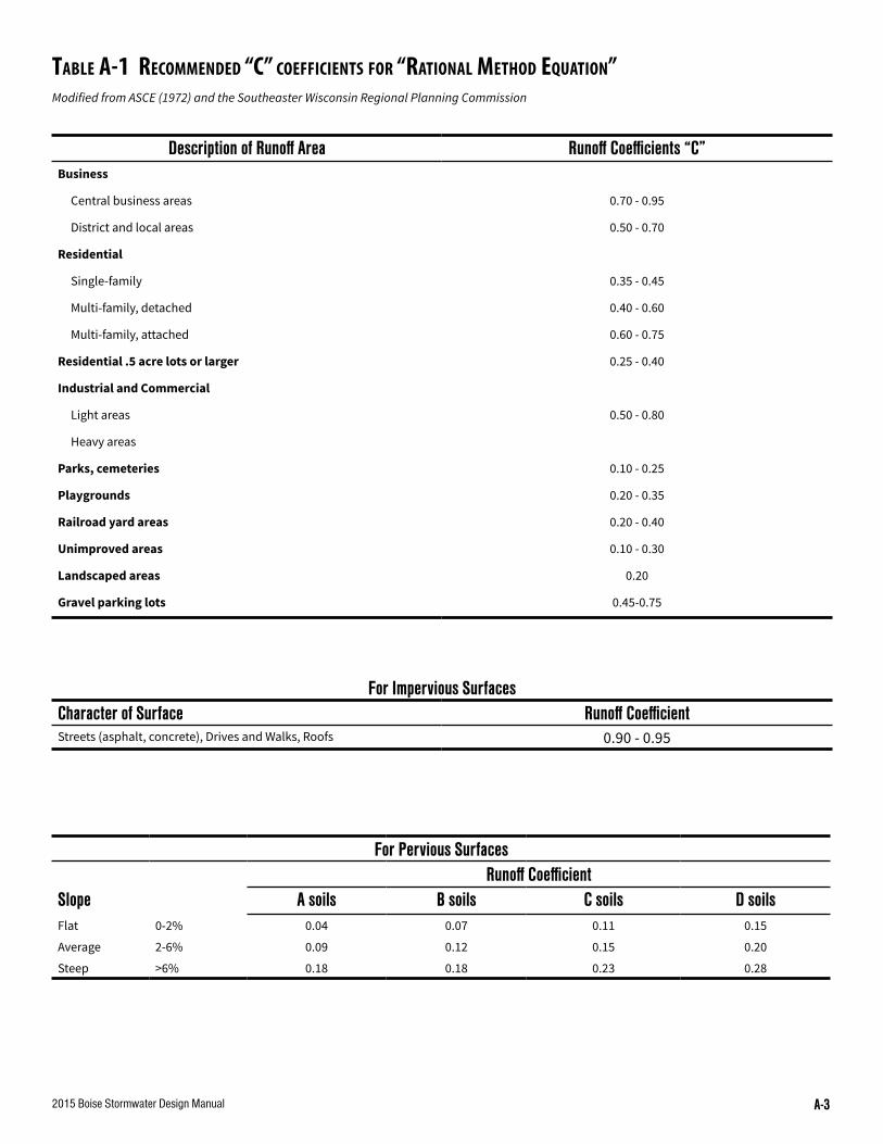
2015 Boise Stormwater Design Manual A-3
table a-1 reCommenDeD “C” CoeFFiCientS For “rational methoD equation”Modified from ASCE (1972) and the Southeaster Wisconsin Regional Planning Commission
Description of Runoff Area Runoff Coefficients “C”Business
Central business areas 0.70 - 0.95
District and local areas 0.50 - 0.70
Residential
Single-family 0.35 - 0.45
Multi-family, detached 0.40 - 0.60
Multi-family, attached 0.60 - 0.75
Residential .5 acre lots or larger 0.25 - 0.40
Industrial and Commercial
Light areas 0.50 - 0.80
Heavy areas
Parks, cemeteries 0.10 - 0.25
Playgrounds 0.20 - 0.35
Railroad yard areas 0.20 - 0.40
Unimproved areas 0.10 - 0.30
Landscaped areas 0.20
Gravel parking lots 0.45-0.75
For Impervious SurfacesCharacter of Surface Runoff CoefficientStreets (asphalt, concrete), Drives and Walks, Roofs 0.90 - 0.95
For Pervious SurfacesRunoff Coefficient
Slope A soils B soils C soils D soilsFlat 0-2% 0.04 0.07 0.11 0.15
Average 2-6% 0.09 0.12 0.15 0.20
Steep >6% 0.18 0.18 0.23 0.28

2015 Boise Stormwater Design ManualA-4
C. Steps for the Peak Discharge Rate (TR-55) (calculated for pre-and post-development)
A = contributing drainage area to site
RCN = runoff curve number
Tc = time of concentration
P = rainfall from specified event
Ia = initial abstraction
Qu = unit peak discharge
Q = site runoff
Fp = pond and wetland adjustment factor
Qp = peak discharge
1. Calculate the contributing drainage area.
Use USGS topographic maps, site visits, and other available information.
2. Calculate the Runoff Curve Number (RCN).
a. Use NRCS maps and site visits to determine soil types within the drainage area.
b. Determine the Hydrologic Soils Group (HSG) for soils identified in step 2a.
c. Determine land use, cover type, treatment, hydrologic condition, % impervious, and % connected/unconnected impervious area ratio.
d. Develop a composite land use and HSG map from the information in 2a-2c.
e. Select RCNs from appropriate charts (TR-55) .
f. Compute a weighted RCN for the entire drainage area.
3. Calculate the site time of concentration (Tc). Determine sheet flow, shallow concentrated flow and channel flow from the most hydraulically distant point in the drainage area to the drainage discharge point at the boundary site.
4. Determine rainfall distribution type. Use Type II for Idaho.
5.Determine % of ponds and wetlands in the drainage area. Measure from USGS topographic sheet.
6. Select design frequency storms to be evaluated.
7. Determine 24 hour site rainfall amounts (P) for each design storm. Use NOAA Atlas II for Idaho.
8. Determine Initial Abstraction (Ia). Initial abstraction is a repre- sentation of interception, initial infiltration, surface depression storage, and evapo-transpiration.
This value obtained from TR-55 chart based on the site’s RCN.
9. Calculate the Ia/P ratio.
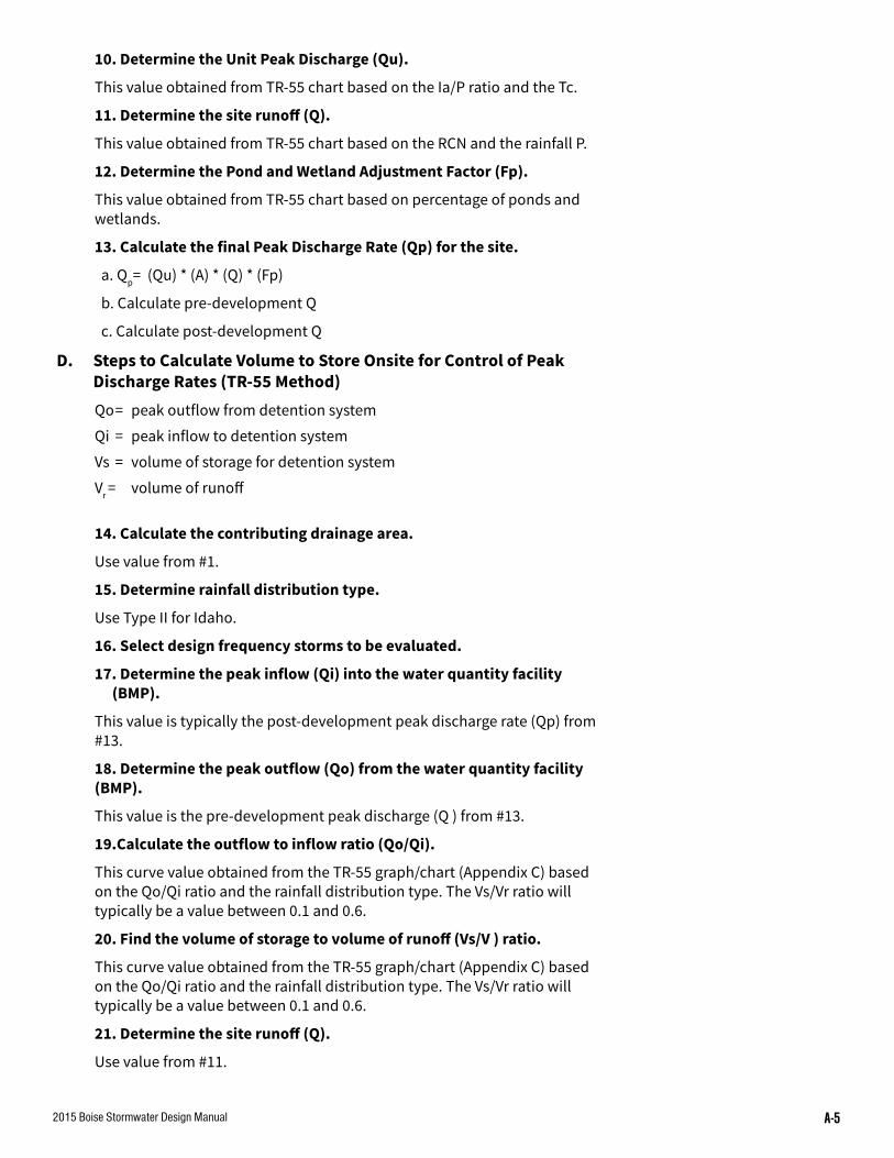
2015 Boise Stormwater Design Manual A-5
10. Determine the Unit Peak Discharge (Qu).
This value obtained from TR-55 chart based on the Ia/P ratio and the Tc.
11. Determine the site runoff (Q).
This value obtained from TR-55 chart based on the RCN and the rainfall P.
12. Determine the Pond and Wetland Adjustment Factor (Fp).
This value obtained from TR-55 chart based on percentage of ponds and wetlands.
13. Calculate the final Peak Discharge Rate (Qp) for the site.
a. Qp= (Qu) * (A) * (Q) * (Fp)
b. Calculate pre-development Q
c. Calculate post-development Q
D. Steps to Calculate Volume to Store Onsite for Control of Peak Discharge Rates (TR-55 Method)Qo = peak outflow from detention system
Qi = peak inflow to detention system
Vs = volume of storage for detention system
Vr = volume of runoff
14. Calculate the contributing drainage area.
Use value from #1.
15. Determine rainfall distribution type.
Use Type II for Idaho.
16. Select design frequency storms to be evaluated.
17. Determine the peak inflow (Qi) into the water quantity facility (BMP).
This value is typically the post-development peak discharge rate (Qp) from #13.
18. Determine the peak outflow (Qo) from the water quantity facility (BMP).
This value is the pre-development peak discharge (Q ) from #13.
19.Calculate the outflow to inflow ratio (Qo/Qi).
This curve value obtained from the TR-55 graph/chart (Appendix C) based on the Qo/Qi ratio and the rainfall distribution type. The Vs/Vr ratio will typically be a value between 0.1 and 0.6.
20. Find the volume of storage to volume of runoff (Vs/V ) ratio.
This curve value obtained from the TR-55 graph/chart (Appendix C) based on the Qo/Qi ratio and the rainfall distribution type. The Vs/Vr ratio will typically be a value between 0.1 and 0.6.
21. Determine the site runoff (Q).
Use value from #11.

2015 Boise Stormwater Design ManualA-6
22. Calculate the runoff volume (V ).
Vr = (Q)* (A)
23. Calculate the storage volume (Vs) to be allocated for the water quantity facility (BMP).
This is the volume that must be stored onsite to maintain the peak discharge rates from the specified frequency storm events.
(a) Vs = (Vr) * (Vs/V ) [Vs/V from #20].
24. Repeat steps 7 - 23 to determine the required storage volumes for other required design storm frequencies identified in step #6.
NOTE: Outlets from detention facilities must be designed to replicate pre-development discharge conditions for all storm events. This may require evaluating additional storm events to properly design pond outlets.
Water QualityWhen surface management BMPs are used, they must be designed to treat the Water Quality Volume (Vwq). The performance standard for treatment is removal of 80% of the average annual load (post-development conditions) of Total Suspended Solids (TSS). It is presumed that the performance standard for surface management BMPs is met when:
A. Suitable nonstructural practices for source control and pollution prevention are implemented;
B. Stormwater management best management practices (BMPs) are sized to capture the Vwqor treat the water quality design flow; and
C. Stormwater management BMPs are maintained as designed.
1. For each drainage area, list the stormwater BMPs and their order in the engineered system, beginning with the first BMP collecting stormwater from the site. For example, pretreat- ment and conveyance BMPs will typically precede the removal BMPs. For each drainage area, list the BMPs and their respec- tive order with their estimated TSS removal rates.
2. The TSS removal rates are not additive from one BMP to the next, instead the estimated removal rates must be applied consecutively as the TSS load passes through each BMP. For the purposes of this calculation, represent the estimated an- nual TSS load as 1.00 (100%).
3. For each drainage area, apply the BMP estimated removal rate in the order that they occur in the stormwater system. The equation for this calculation is:
Final TSS Removal Rate = (TSS Average Annual Load * BMP 1 Removal Rate) + (Remaining TSS Load After Preceding BMP* BMP 2 Removal Rate) + (Remaining TSS After Preceding BMP * BMP 3 Removal Rate).
4. After all of the BMPs in the initial stormwater system design have been accounted for and their estimated removal rates applied, the Final TSS Removal Rate for each drainage area should be equal to or better than 80% (0.80) or the sliding scale standard, where applicable. If the Final TSS
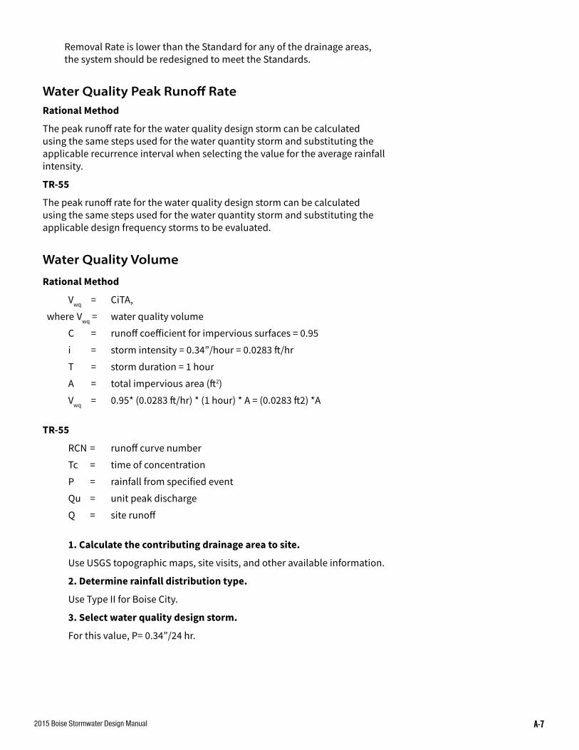
2015 Boise Stormwater Design Manual A-7
Removal Rate is lower than the Standard for any of the drainage areas, the system should be redesigned to meet the Standards.
Water Quality Peak Runoff RateRational Method
The peak runoff rate for the water quality design storm can be calculated using the same steps used for the water quantity storm and substituting the applicable recurrence interval when selecting the value for the average rainfall intensity.
TR-55
The peak runoff rate for the water quality design storm can be calculated using the same steps used for the water quantity storm and substituting the applicable design frequency storms to be evaluated.
Water Quality Volume
Rational Method
Vwq = CiTA,
where Vwq = water quality volume
C = runoff coefficient for impervious surfaces = 0.95
i = storm intensity = 0.34”/hour = 0.0283 ft/hr
T = storm duration = 1 hour
A = total impervious area (ft2)
Vwq = 0.95* (0.0283 ft/hr) * (1 hour) * A = (0.0283 ft2) *A
TR-55
RCN = runoff curve number
Tc = time of concentration
P = rainfall from specified event
Qu = unit peak discharge
Q = site runoff
1. Calculate the contributing drainage area to site.
Use USGS topographic maps, site visits, and other available information.
2. Determine rainfall distribution type.
Use Type II for Boise City.
3. Select water quality design storm.
For this value, P= 0.34”/24 hr.

2015 Boise Stormwater Design ManualA-8
4. Calculate the Runoff Curve Number (RCN) for the impervious areas.
a. Use NRCS maps and site visits to determine soils and types within A.
b. Determine the Hydrologic Soils Group (HSG) for soils identified in a.
c. Determine land use, cover type, treatment, hydrologic condition, % impervious, and % connected unconnected impervious area ratio.
d. Develop a composite land use and HSG map from the information in 4 a-c.
e. Select RCNs from appropriate charts (TR-55).
f. Compute a weighted RCN for the entire drainage area.
5. Determine the site runoff (Q).
This value obtained from TR-55 chart based on the RCN and the rainfall P (inches)
6. Determine the site runoff volume (V)
V=Q*A

2015 Boise Stormwater Design Manual B-1
Introduction
Facilities can be designed to provide water quantity control, water quality treatment or both. Refer to Chapter 2 for information regarding the applicable design storm. The rational formula or the NRCS TR-55 Method may be used.
Oil Separators
Size the CP separator as follows:
1. The separator can be sized as an on-line component or off- line component of the system. If the separator is used off-line, size the separator for the water quality design storm and divert larger storms using an isolation/diversion structure. In-line systems should be sized for the water quantity control design storm.
2. Place coalescing plates less that 3/4” apart and at an angle from 45° to 60° from the horizontal.
3. Calculate the projected (horizontal) surface area of plates required using the following equation:
Ap = Q/Rise rate
where: Ap= projected surface area of the plate in square feet. Note that the actual plate surface area, Aa=Ap*cosine H,
where: H= angle of the plates with the horizontal in degrees, usually varies from 45-60°
Q = design flow (cfm)
Rise rate: 0.033’ per minute. For 60 micron droplets at 10°C.
Seepage Beds
1. Determine runoff volume for site using Rational Formula or NRCS TR-55 Method.
2. Seepage bed sizing is dependent upon percolation rate of native materials and void ratio of seepage bed media. Allowable percolation rates for seepage beds range from 0.5”per hour to 8” per hour. Void ratio of bed media generally ranges from 0.3 to 0.4.
3. Given site configuration and depth to ground water, estimate seepage bed depth. Limit bottom of seepage bed to no more than 10’ below grade for ease of installation and construction safety.
4. Calculate unit length seepage bed capacity, based upon percolation rate (assume percolation rate is percolation amount that will occur over a one hour period) and estimated depth and width of seepage bed.
Unit Length Capacity = (depth) (width) (void ratio of bed media) + (width) (percolation rate) = ft3 of storage /linear feet of bed
5. Calculate the required seepage bed length. Length = Disposal Volume / Unit Length Capacity
APPENDIX B
Calculations for Facility Sizing
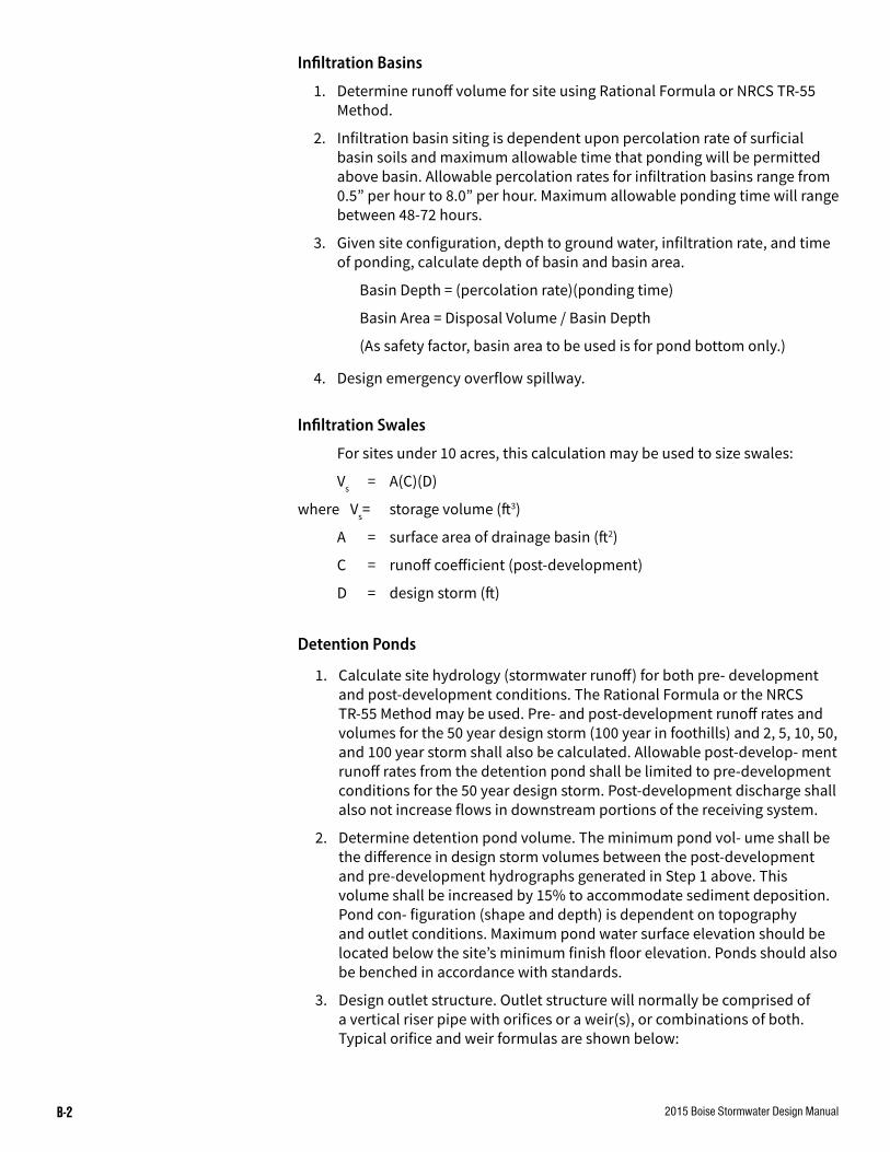
2015 Boise Stormwater Design ManualB-2
Infiltration Basins
1. Determine runoff volume for site using Rational Formula or NRCS TR-55 Method.
2. Infiltration basin siting is dependent upon percolation rate of surficial basin soils and maximum allowable time that ponding will be permitted above basin. Allowable percolation rates for infiltration basins range from 0.5” per hour to 8.0” per hour. Maximum allowable ponding time will range between 48-72 hours.
3. Given site configuration, depth to ground water, infiltration rate, and time of ponding, calculate depth of basin and basin area.
Basin Depth = (percolation rate)(ponding time)
Basin Area = Disposal Volume / Basin Depth
(As safety factor, basin area to be used is for pond bottom only.)
4. Design emergency overflow spillway.
Infiltration Swales
For sites under 10 acres, this calculation may be used to size swales:
Vs = A(C)(D)
where Vs= storage volume (ft3)
A = surface area of drainage basin (ft2)
C = runoff coefficient (post-development)
D = design storm (ft)
Detention Ponds
1. Calculate site hydrology (stormwater runoff) for both pre- development and post-development conditions. The Rational Formula or the NRCS TR-55 Method may be used. Pre- and post-development runoff rates and volumes for the 50 year design storm (100 year in foothills) and 2, 5, 10, 50, and 100 year storm shall also be calculated. Allowable post-develop- ment runoff rates from the detention pond shall be limited to pre-development conditions for the 50 year design storm. Post-development discharge shall also not increase flows in downstream portions of the receiving system.
2. Determine detention pond volume. The minimum pond vol- ume shall be the difference in design storm volumes between the post-development and pre-development hydrographs generated in Step 1 above. This volume shall be increased by 15% to accommodate sediment deposition. Pond con- figuration (shape and depth) is dependent on topography and outlet conditions. Maximum pond water surface elevation should be located below the site’s minimum finish floor elevation. Ponds should also be benched in accordance with standards.
3. Design outlet structure. Outlet structure will normally be comprised of a vertical riser pipe with orifices or a weir(s), or combinations of both. Typical orifice and weir formulas are shown below:

2015 Boise Stormwater Design Manual B-3
a. Orifice Equation
Q = Ca √2gh
where c = orifice coefficient (normally, a coefficient of between .6 and .65 is used)
d = diameter of orifice (ft2)
g = gravitational constant = 32.2 ft/sec2
h = head on orifice, in feet (vertical distance between orifice centerline and water surface elevation at structure)
b. Weir Equation
Q = cLh3/2
where Q = flow rate in ft3/second
c = weir coefficient (this coefficient is dependent on the type of weir used)
L = length of weir crest (ft)
h = head above weir crest (vertical distance between weir rest and water surface elevation at structure)
Outlet structure, in conjunction with pond storage is designed to limit post-development discharge rates to pre-development levels. As a minimum, outlet structure shall control post-development runoff rates to pre-development conditions for the design storm. For the lesser magnitude storms (5, 10, 50 year), structures shall also approximate these pre-development discharge conditions.
Based upon pond size and allowable flow rates, estimate sizes of outlet orifices/weirs. Generate stage-discharge and stage-storage curves. With the stage-storage and stage-discharge information, route post-development hydrograph through pond. Routing can be done by manual calculations in accordance with established engineering practices or by suitable computer program. Compare routed pond outflow hydrograph with minimum design requirements. Adjust either pond configuration or outlet controls as required, to meet outlet requirements.
4. Design emergency overflow spillway. Emergency overflow spillway should be designed to pass a 100 year flood event. Design and siting of spillway shall assume that the primary outlet structure is not operational.

2015 Boise Stormwater Design ManualB-4
EVAPORATION POND MASS BALANCE DESIGN
Nonnal Monthly Evaporation Monthly Monthly Cumulative
Precip. Pond Inflow Evaporation Storage Storage (inches) (fl')
(in.Imo.) (fl') (fl') (tt3)
Oct
Nov
Dec
Jan
Feb
Mar
Apr
May
June
July
Aug
Sept . . Notes: *Apnl is maximum month for pond storm water storage
•At least one month should show a negative pond volume (indicates a dry pond condition)
FINAL POND SIZING
Maximum Allowance for
Maximum Monthly Maximum 24-hour Runoff Volume montlhly volume debris and Total Pond Maximum Month Volume (It')
precip. for max. form 24-hour plus 24-hour sedimentation Design Volume
month (inches) stonn (It') storm volume
(It') (add 15%)
April
table b-1 eVaPoration PonD CalCulationS

2015 Boise Stormwater Design Manual B-5
Biofiltration Swales
The standard design calculation for biofiltration swale sizing is given as Manning’s equation, the basic equation of open channel flow.
v = (1.49/n) r2/3 s1/2 or
Q = (1.49/n)A r2/3 s1/2
where v = Velocity (ft/s)
n = Manning’s roughness coefficient
A = Cross-sectional flow area (ft2)
r = Hydraulic radius (ft) = A/wetted perimeter s = Slope (ft/ft)
Q = Flow rate (cubic ft/s, cfs)
Grass Buffer Strips
The buffer strip length is defined as the length of the flowpath through the strip. Strip width is typically the same as the extent of pavement along the upstream edge of the strip. In sizing filter strips, the length is normally the dimension to be sized.
1. Calculate design flow. Determine the water quality design flow, Qwq
2. Calculate design flow depth. The design flow depth is calculated based on the width of the buffer strip (typically equivalent to the length of the edge of impervious surface contributing flow to the filter strip) and the longitudinal slope of the filter strip (parallel to the direction of flow) using a form of Manning’s equation as follows:
Qwq = 1.49/nW df1.67s.5
where Q = water quality design flow, in cubic feet per second (cu ft/sec)
n = Manning’s roughness coefficient = 0.40
W = width of buffer strip perpendicular to the direction of flow (ft) (= length of impervious surface contributing flow)
df = design depth of flow (ft), which is also assumed to be the hydraulic radius (maximum 1”, or 0.083’; see standards below)
s = longitudinal slope of buffer strip parallel to the of flow, in feet per foot averaged over the width of the filter strip; must be between 0.01 and 0.20ft/ft).
Rearranging the above equation, the design depth of flow can be calculated using the following equation:
df = (Q n/1.49Ws.5)0.6
If the calculated flow depth exceeds 1” (0.083’), the design flow rate routed through the strip must be reduced. If this is not feasible, it is not possible to use a buffer strip.
3. Calculate design flow velocity through buffer strip. The design flow velocity Vwq is based on the water quality design flow rate, the width of the buffer strip, and the calculated design flow depth from Step 2 using the following equation:

2015 Boise Stormwater Design ManualB-6
v = Qwq/Wdf
where v = design flow velocity(ft/sec)
w = strip width (ft) (parallel to the edge of pavement) df = water depth (ft)
If v exceeds 0.5’ per second, a buffer strip may not be used. Either redesign the site to provide a gentler longitudinal slope for the s.
4. Calculate required length of buffer strip. Determine the required length L of the buffer strip to achieve a desired hy- draulic residence time of at least nine minutes (540 seconds) using the following equation:
L = 540v
where L = buffer strip length (ft)
v = design flow velocity from Step 3 (ft/sec)

Boise Stormwater Design Manual C-1
APPENDIX C
Bioretention Soil Mix (BSM) Requirements
Bioretention soil media (BSM) is a mixture of sand, compost and soil used in stormwater treatment systems that infiltrate stormwater into the ground or provide stormwater treatment prior to discharge to off- site facilities. Treatment systems that use BSM include grass buffer strips, infiltration swales and infiltration basins. BSM provides critical stormwater treatment functions including:
a. Provides supporting media for vegetation (Vegetation transpires water, takes up pollutants contained in stormwater, and helps to maintain soil permeability.
b. Allows moderately rapid infiltration rates
c. Adsorbs metals and other chemicals contained in stormwater
The bioretention soil media and soils underlying these treatment facilities are the principal design elements for determining infiltration capacity, sizing, and associated conveyance structures. The BSM placed in a grass buffer strip, infiltration swale or infiltration basin is typically composed of a highly permeable sandy mineral aggregate mixed with compost and will often have a higher infiltration rate than the surrounding subgrade.
The soil media and plants must work together to provide effective flow control and water quality treatment in bioretention areas. Soil mixes for bioretention areas need to balance four primary design objectives to provide optimum performance:
• Provide high enough infiltration rates to meet desired surface water drawdown and system dewatering.
• Provide infiltration rates that are not too high in order to optimize pollutant removal capability.
• Provide a soil mix that supports long-term plant and soil health.
• Balance nutrient availability and retention to reduce or eliminate nutrient export during storm events.
General Soil Media (BSM) Requirements
BSM shall achieve a long-term, in-place infiltration rate of 5 inches/hour minimum, 8 inches/hour maximum. The long-term hydraulic conductivity rate should not be less than 5 inches per hour when tested with a double ring infiltrometer in accordance with ASTM D3385; - Standard Test Method for Infiltration Rate of Soils in Field Using Double Ring Infiltrometer, a single ring infiltrometer, a Modified Philip-Dunne Infiltrometer, or other approved methods. Test results shall be provided to the City by the BSM manufacturer.* It shall support plant growth while providing pollutant treatment. In order to achieve these two goals, the BSM shall consist of a mixture of sand, fines, and compost. The following composition includes the measurements for determining the BSM by volume:
*For design purposes, the infiltration rate for the drainage system shall be the lesser of native soil below the facility or the BSM.

Boise Stormwater Design ManualC-2
BSM Composition
Sand Sandy Loam Compost
Sand Silt Clay
Volume 60% 20% 20%
Submittals
Product Data: Submit manufacturer’s product data and installation instructions. Include required substrate preparation, list of materials, application rate/testing, and infiltration rates.
Verifications: Manufacturer shall submit a letter of verification that the products meet or exceed all physical property, endurance, performance and packaging requirements.
Tests should be conducted no more than 120 days prior to the delivery date of the BSM to the project site. Batch-specific test results and certification will be required for projects installing more than 200 cubic yards of BSM.
The BSM supplier shall submit the following to Boise City Public Works for approval:
A. A one-gallon sample of mixed BSM.
B. Grain size analysis results of the sand component performed in accordance with American Society for Testing and Materials (ASTM) D422, Standard Test Method for Particle Size Analysis of Soils.
C. Organic matter content test results of compost. Organic matter content tests shall be performed in accordance with ASTM F 1647, Standard Test Methods for Organic Matter Content of Athletic Field Rootzone Mixes or Testing Methods for the Examination of Compost and Composting (TMECC) 05.07A, Loss-On-Ignition Organic Matter Method.
D. Constant head permeability results of the mixed BSM. Constant head permeability testing in accordance with ASTM D2434, Standard Test Method for Permeability of Granular Soils (Constant Head) shall be conducted on a minimum of two samples with a 6-inch mold and vacuum saturation.
E. Provide the following information about the testing laboratory(ies) including:
1. Name of laboratory(ies)
2. Contact person(s)
3. Address(es)
4. Phone contact(s)
5. Email address(es)
6. Qualifications of laboratory(ies), including use of ASTM and U.S. Department of Agriculture(USDA) method of standards
Sand Specifications for BSM
Sand shall be thoroughly washed prior to delivery and free of wood, waste, and coatings such as clay, stone dust, carbonate, or any other deleterious material.

Boise Stormwater Design Manual C-3
Sand for BSM should be analyzed by a qualified lab using #200, #100, #50, #30, #16, #8, #4, and 3/8-inch sieves (ASTM D422) and meet the following gradation:
Percent Passing (by weight)Sieve Size Min. Max.3/8 inch 100 100
No.4 90 100
No. 8 70 100
No. 16 40 95
No. 30 15 70
No. 50 5 55
No. 100 0 15
No. 200 0 5
Sandy Loam Specifications for BSM
Sandy loam soil for the BSM shall be free of wood, waste, coating such as stone dust, carbonate, etc., or any other deleterious material. It shall be tested for phosphrous content using the Mehlich 3 method: 15-60 mg/kg P.
Sandy loam soil shall comply with the following specifications by weight based on ASTM D422:
A. 70-90 percent sand
B. 0–30 percent silt
C. 2–15 percent clay
NOTE: These ranges were selected from the USDA soil textural classification for a sandy loam, such that clay content does not exceed 15 percent of sandy loam.
Compost Soil Specifications for BSM
A qualified lab shall analyze compost using No. 200 and 1/2-inch sieves (ASTM D422 or as approved by Boise City), and meet the following gradation:
Percent Passing (by weight)Sieve Size Min. Max.1/2 inch 100 100
No. 200 0 5
Compost shall be a well-decomposed, stable, weed-free organic matter source derived from waste materials including yard debris, wood wastes or other organic materials, not including manure or biosolids from industrial wastewater or sewage sludge. Compost shall comply with the following requirements:

Boise Stormwater Design ManualC-4
Parameter Method Requirement UnitsBulk Density 1080-1400 dry lbs/cubic yd
Moisture Content Gravimetric 35%-65% dry solids
Organic Matter ASTM F 1647 Standard Test Methods for Organic Matter Content of Athletic Field Rootzone Mixes or Testing Methods for the Examination of Compost and Composting (TMECC) 05.07A “Loss-On-Ignition Organic Matter Method.”
35%-65% dry weight
Inert Material/Physical Contaminants
<1% dry weight
pH Saturation Paste 6.0-8.0
Carbon:Nitrogen Ratio - 15:1-35:1
Maturity/Stability TMECC05 or Solvita* >5 Index value
Pathogens
Salmonella - <3 MPN per4 g
Fecal Coliform <1000 MPN per 1g
*Solvita is a measurement system for carbon dioxide (CO2) and ammonia (NH3). The results can be used to assess soil health (biology) and compost maturity (CO2+NH3 gas emissions).
BSM Specifications
BSM shall be free of roots, clods stones larger than 1-inch in the greatest dimension, pockets of coarse sand, noxious weeds, sticks, lumber, brush, and other litter. It shall not be infested with nematodes or undesirable disease-causing organisms such as insects and plant pathogens. BSM shall be friable and have sufficient structure in order to give good aeration to the soil. The following specifications should govern the bulk BSM.
Gradation Limit: The definition of the BSM should be the following USDA classification scheme by weight:
A. Sand: 85–90 percent
B. Silt: 10 percent maximum
C. Clay: 5 percent maximum
The final BSM shall meet the following standards. Testing results from the following specifications shall be submitted for approval prior to BSM acceptance.
Parameter Method Requirement UnitsOrganic Matter Loss on Ignition 2%-5% dry weight
pH Saturation Paste 6.0-8.0
Cation Exchange Capacity (CEC)
- > 5 meq/100 g of dry soil
BSM Testing
The Contractor shall not place any soils or soil mixes until the City Inspector has reviewed and confirmed the following:
a. Soil mix delivery ticket(s). Delivery tickets shall show that the full delivered

Boise Stormwater Design Manual C-5
amount of soil matches the product type, volume and Manufacturer named in the submittals.
b. Visual match with submitted samples. Delivered product will be compared to the submitted sample, to verify that it matches the submitted sample.
Boise City or the Developer’s Engineer may inspect any loads of soil on delivery and stop placement if it is determined that the delivered soil does not appear to match the submittals; and require sampling and testing of the delivered soil, before authorizing soil placement. All testing costs shall be the responsibility of the Contractor.
BSM Mixing and Placement
These guidelines shall be followed to ensure proper BSM mixing and placement:
A. Erosion and sediment control practices during construction shall be employed to protect the long-term functionality of the bioretention facility. The following practices shall be followed for this reason:
1. Provide erosion control in the contributing drainage areas to the facility and stabilize upslope areas.
2. Facilities shall not be used as temporary sediment control facilities, unless installation of all bioretention-related materials are withheld towards the end of construction, allowing the temporary use of the location as a sediment control facility, and appropriate excavation of sediment occurs prior to installation of bioretention materials.
B. Do not excavate, place soils, or amend soils during wet or saturated conditions.
C. Operate equipment adjacent to the facility. Equipment operation within the facility shall be avoided to prevent soil compaction. If machinery must operate in the facility, use lightweight, low ground-contact pressure equipment with turf type tires or wide-track loaders.
D. If constructing an infiltrating facility, the subgrade shall be ripped or scarified to a minimum depth of 9 inches to promote greater infiltration.
F. Minimum depth of BSM soil in a biofiltration drainage facility is 18 inches unless otherwise approved by City. If trees are to be planted in the biofiltration facility the minimum depth of BSM soil shall be 24 inches.
G. Place soil in 6- to 12-inch lifts with machinery adjacent to the facility (to ensure equipment is not driven across soil). If working within the facility, to avoid over-compacting, place first lifts at far end from entrance and place backwards towards the entrance.
H. Allow BSM lifts to settle naturally, lightly water to provide settlement and natural compaction between lifts. After lightly watering, allow soil to dry between lifts. Soil cannot be worked when saturated, so this method shall be used with caution to ensure dry conditions. After all lifts are placed, wait a few days to check for settlement, and add additional media as needed. No mechanical compaction will be allowed.
I. Vehicular traffic and construction equipment shall not drive on, move onto, or disturb the BSM once placed and water-compacted.
J. Rake bioretention soil as needed to level out. Verify BSM elevations before applying mulch or installing plants.
Note: Fertilizers are not to be applied to the BSM soils. Operation and Maintenance (O&M) Manual for the project shall specify this requirement.

Boise Stormwater Design ManualC-6

Boise Stormwater Design Manual D-1
APPENDIX D
Hydrologic and Hydraulic Graphs
Figure D.1 rainFall intenSity, Duration anD FrequenCy relationShiP

Boise Stormwater Design ManualD-2
Figure D.2 SurFaCe Flow time CurVeS

Boise Stormwater Design Manual D-3
Figure D.2 aPProximate Detention baSin routing For rainFall tyPeS i, ia, ii, anD iii

Boise Stormwater Design ManualD-4

Boise Stormwater Design Manual E-1
APPENDIX E
General Testing Procedures
General Notes
• For seepage beds, infiltration basins, and infiltration swales, a minimum field infiltration rate of 0.5” per hour is required. Areas yielding a lower rate preclude these practices. For sites with infiltration rates that are more than 0.5" - 8.0" per hour, a 12” layer of ASTM fine grade C-33 sand, or greater, is required at the bottom of the facility.
• Number of required borings is based on the size of the proposed facility. Testing is done in two phases: 1) initial feasibility, and 2) concept design.
• Testing is to be conducted by a qualified professional. The professional shall either be a registered professional engineer in the State of Idaho, a soils scientist, or a geologist licensed in the State of Idaho.
Initial Feasibility Testing
Feasibility testing is conducted to determine whether full scale testing is necessary, screen unsuitable sites, and reduce testing costs. Initial testing involves either one field test per facility, regardless of type, size, or previous testing data, such as:
• percolation testing onsite, within 200 feet of the proposed BMP location, and on the same contour that can establish initial rate, water table, and/or depth to bedrock
• geotechnical report for the site prepared by a qualified geo-technical consultant
• Natural Resources Conservation Service (NRCS) County Soil Mapping showing Hydrologic Soil Classifications (Type A, B, C, D)
Concept Design Testing
If the results of initial feasibility testing as determined by a qualified professional show that an infiltration rate of greater than 0.5”/hour is probable, then the number of soil borings shall be one soil boring and one infiltration test for infiltration areas up to 1000 s.f. For infiltration facilities greater than 1000 s.f., one additional soil boring and one additional infiltration test for each additional 1000 s.f. of infiltration area is required. If test borings show uniform subsurface characteristics throughout the proposed stormwater facility location, then only one infiltration test/2000 ft2 is required.
Documentation
Infiltration testing data shall be documented, and include a description of the infiltration testing method. This is to ensure that the tester under- stands the procedure.
As part of a design submittal, the infiltration facility must be sized and documented with a calculation. The sizing of an infiltration facility is primarily related to the design infiltration rate. Infiltration rates should be based on laboratory or in-situ tests that correlate or measure infiltration. Some commonly used test methods are laboratory gradations (ASTM C-136 and ASTM D-1140 often including the No. 270 sieve size for correlation with agricultural guides) used in conjunction with recognized infiltration guidelines (e.g. Ada County

Boise Stormwater Design ManualE-2
Highway District Policy Development Manual), in-situ percolation tests (State of Idaho - Technical Guidance Manual for Individual and Subsurface Sewage Disposal), laboratory permeability tests (e.g. ASTM D-2434 or D-5084), full scale infiltrations tests (designed by a professional), and other tests.
A design infiltration rate should be developed from measured infiltration rate(s) for each infiltration facility area. A qualified professional should recommend a design infiltration rate that considers the potential variability of the area in the immediate vicinity of the infiltration facility, possible degradation by construction practices, the reproducibility of the test method, and the applicability of the test method. Measured infiltration rates should be appropriately reduced to develop the design infiltration rate.
The drainage design professional, based on the geotechnical report findings, shall state the final infiltration rate reduction factors (infiltration basin size safety factor). The factor recommended by the design professional may be larger to account for site variability or construction considerations.
Calculations for the sizing of an infiltration facility should include the following information for each infiltration area:
• The test method used to correlate or measure infiltration
• The measured infiltration rate
• The reduction factor used to develop a design infiltration rate
• The design infiltration rate (inches per hour)
A general validation of the appropriate selection of a design infiltration rate will occur after construction of the drainage facility through the required swale performance infiltration test. Drainage design professionals may request the opportunity to review the condition of the subgrade of infiltration facilities during construction to verify that the exposed sub- grade condition is similar to the assumed design condition.
Test Pit/Boring Requirements
1. Dig a standard soil boring to a depth of 10’ below the pro- posed facility bottom.
2. Determine depth to groundwater table (if within 10’ of pro-posed bottom) upon initial digging or drilling, and again 24 hours later.
3. Determine United States Department of Agriculture (USDA) or Unified Soil Classification (USC) system textures at the proposed bottom.
4. Determine depth to bedrock (if within 5’ of proposed bottom).
5. The soil description should include all soil horizons and vadose zone.
6. The location of the boring shall correspond to the BMP location.
Infiltration Testing Requirements
Method #1 1. Install casing (solid 5” diameter, 30” length) to 24” below proposed BMP
bottom.
2. Remove any smeared soiled surfaces and provide a natural soil interface where water may percolate. Remove all loose material from the casing. Upon the tester’s discretion, a 2” layer of coarse sand or fine gravel may be placed to protect the bottom from scouring and sediment. Fill casing

Boise Stormwater Design Manual E-3
with clean water to a depth of 24” and allow to presoak for 24 hours.
3. 24 hours later, refill casing with another 24” of clean water and monitor water level (measured drop from the top of the casing for one hour. Repeat this procedure (filling the casing each time) three additional times, for a total of four observations. Upon the tester’s discretion, the final field rate may either be the average of the four observations, or the value of the last observation. The final rate shall be reported in inches/hour.
4. The test location shall correspond to the BMP location.
5. Upon completion of the testing, the casings shall be immediately pulled.
Method #2 - Open-Pit Falling Head Infiltration Testing
The open-pit, falling-head procedure is based on the Environmental Protection Agency (EPA) Falling Head Percolation Test Procedure (EPA 1980). The test is performed in an open excavation and is a test of the combination of vertical and lateral infiltration.
Site Preparation
Excavate a minimum 2-foot by 2-foot hole into the native soil to the elevation of the proposed facility bottom. The test is typically conducted in a machine excavated pit or a pit dug by hand using a shovel. A smooth excavation bucket is preferred to limit loose material in the bottom of the test hole. Remove all loose material in bottom of hole as it will artificially reduce the tested infiltration rate. A 2-inch layer of coarse sand or fine gravel may be placed to protect the bottom from scour and sloughing, which can artificially reduce the tested infiltration rate.
Presoaking
Fill the hole with clean water to a minimum of 1 foot above the soil to be tested, and maintain this depth of water for at least 24 hours to presoak the native material. Presoaking is necessary in all material types as hard pan or other confining layers may exist under a material that may appear to be free-draining.
Testing
Determine how the water level will be accurately measured. The measurements should be made with reference to a fixed point. A lath placed across the test pit, or a sturdy beam placed across the top of the pit, are convenient reference points. The tester and excavator should conduct all testing in accordance with OSHA safety regulations.
After the presaturation period, refill the hole with water to 12 inches above the soil and record the time. Measure the water level to the nearest 0.01 foot (⅛ inch) at 10-minute intervals for a total period of 1 hour, or until all the water has drained. In faster-draining soils (sands and gravels), it may be necessary to shorten the measurement interval to obtain a well-defined infiltration rate curve. Constant-head tests may be substituted for falling-head tests, at the discretion of the professional overseeing the infiltration testing.
Repeat the test. Successive trials should be run until the percent change in measured infiltration rate between two successive trials is minimal. The trial should be discounted if the infiltration rate between successive trials increases. At least four trials must be conducted for comparisons. After each trial, the water level is readjusted to the 12-inch level. Enter results into a data table.
Design Infiltration Rate

Boise Stormwater Design ManualE-4
The average infiltration rate over the last trial should as to calculate the infiltration rate. The final rate must be reported in inches per hour. No more than 8 inches per hour may be used for the design rate.
For very rapidly draining soils, it may not be possible to maintain a water head above the bottom of the test pit. If the infiltration rate meets or exceeds the flow of water into the test pit, conduct the test in the fol¬lowing manner:
1. Approximate the area over which the water is infiltrating.
2. Using a water meter, bucket, or other device, measure the rate of water discharging into the test pit.
3. Calculate the infiltration rate by dividing the rate of discharge (cubic inches per hour) by the area over which it is infiltrating (square inches).
Upon completion of the testing, the excavation must be backfilled.
Method #3 - Double-Ring Infiltrometer Infiltration Testing
In this test, the vertical infiltration rate is isolated. Since water moves out through the sides of a facility as fast as through the bottom in most cases, this test is good for facilities that primarily will be infiltrating through its bottom. An inner ring is used to measure water drop over time; an outer ring minimizes lateral water movement from the inner ring. The test can be performed at different depths, but the rings must penetrate at least 2 inches below the ground’s surface. At least 6 inches of both cylinders must be above the surface; therefore, a cylinder should be a minimum of 8 inches high. If the proposed infiltration facility will pond water to a depth greater than 6 inches, taller rings will be needed to simulate the design head. The double-ring infiltrometer test measures the infiltration rate of a very small and specific area, so if the proposed infiltration gallery has a large area, multiple measurements within the area are suggested to properly assess the site’s suitability.
Supplies
• Two impermeable cylinders (the inner ring should be no smaller than 4 inches in diameter and equal 50 to 70% of the outer ring diameter; for example, use an 8-inch inner ring with a 12¬ inch outer ring) .
• Water source

Boise Stormwater Design Manual E-5
• Timer
• Measuring device (ruler, measuring tape)
• Flat wooden board that covers diameter of cylinders to push the cylinders into the ground
• Rubber mallet
• Log sheets and writing utensil or computer
Boise City requires the double-ring infiltrometer test follow ASTM 3385-94 standards. Basic steps are described below.
1. Site Preparation
In an area in or near the proposed infiltration area, excavate to the depth of the bottom of the proposed facility.
Drive the larger outer ring in evenly, at least 2 inches (can be more, but make sure at least 6 inches of the cylinder is above ground) into the ground by setting the flat wooden board atop the cylinder and firmly striking it with the rubber mallet.
Center the inner ring within the outer ring and follow the same procedure as above with the wooden board and mallet. Make sure the bottoms of both rings (underground) are at the same depth. Different depths or strata can be tested by excavating a pit area, but make sure the rings are easily accessible and that water can easily be added over a period of hours.
2. Presoaking
Before beginning the infiltration test, the test area must be presoaked and a measurement interval time established. To presoak the area, fill the inner and outer ring to the brim or water level mark with water. Keep the water level above 4 inches for 30 minutes. At the end of 30 minutes, refill the rings completely.
Measure the water depth in the inner ring and wait another 30 minutes and then measure the water depth again to determine the drop in water level. If the drop is equal to or greater than 2 inches, use 10-minute intervals; if less than 2 inches, use a 30-minute interval.
3. Testing
Fill the rings to the brim or to a set water level. Using the established interval times and from a fixed reference, measure and record the water level drop in the inner ring at each interval. After each recording, stop the timer, refill the rings and restart the timer. When eight readings have been collected or the water-level drop stabilizes (when the highest and lowest measurement within four consecutive readings is no more than a ¼-inch difference) no more measurements are required.
4. Design Infiltration Rate
The infiltration rate of the test area is determined by averaging the measurements taken during the stabilized rate, and should be expressed in inches per hour.

2015 Boise Stormwater Design ManualE-6
Method #4 - ASTM C1701 (for PICP surfaces)
The Standard Test Method for Infiltration Rate on In Place Pervious Concrete is the method to be used for Permeable Interlocking Concrete Pavers (PICP). Contact ASTM International for more information on this testing method.
Laboratory Testing
Grain size sieve analysis and hydrometer tests, where appropriate, may be used to determine USDA soils classification and textural analysis. Visual field inspection by a qualified professional may also be used, provided it is documented. The use of lab testing to establish infiltration rates is prohibited.
Swale Performance Testing
Bulk infiltration testing for swales and basins consists of filling the swale or basin with water to the 50 year storm event level to test the infiltration rate. The swale should infiltrate the water within the time utilized in the design calculations. For larger swales with capacities greater than 5000 gallons (668 cubic feet) a section of the swale equal to 2000 gallons may be tested by damming an appropriately sized section, not less than 5% of the swale area. Recommended dam materials are sandbags with visqueen. On swales greater than 1500 cubic feet (11,220 gallons) in size, two tests will be required.
An acceptable infiltration test is one where all water is infiltrated within the test period. For example, where 75% of the test volume is infiltrated within the first 24 hour period and all water is infiltrative within the next 24 hour period (48 hours from the start of the test). Please note that swale/basin testing shall not be performed until system vegetation has been established.
If the proposed infiltration tests cannot satisfy the above criteria, the swale must be reconstructed. An investigation to determine the cause of unacceptable infiltration rate performance is important prior to re- construction. Reconstruction may be based upon either of the following two conditions:
• Inadequate or improper plan by system designer
• Contractor failed to construct swale in accordance to plan and material specification requirements
For those situations where a swale fails the infiltration test, the City of Boise is to be notified of the failure, the reasons for the failure, and either the corrective construction measures or the modified swale design. When a modified design is required, designer shall submit modified plan to the City for approval before swale modifications commence.
Swale/Basin Test Guidance
1. Identify swale/basin size to determine number of tests required.
2. For larger systems, enclose sections of the swale/basin to provide for infiltration tests with approximately 2000 gallon capacities. If in-situ sand filters have been included in the constructed swale, the proportion of the swale with and without sand filtration is to reflect the overall swale drain- age design objectives. For example, if the design storm is to be infiltrated proportionately 25% through the vegetated or permeable soil section and 75% through in-situ sand filters, then the size and location of the swale test shall approximate these same proportions.

2015 Boise Stormwater Design Manual E-7
3. Place a stake and note the elevation within the swale or swale section to be tested that reflects 25% of the design storm volume (maximum swale/basin volume at the end of the first 24 hour test period).
4. Fill the swale/basin or the section of the swale/basin to be tested with the design test volume. Filling procedures should use low velocity and spreading techniques in order to prevent any erosion or damage to the established vegetation. Make a note as to the time and date that the swale basin is filled to the testing limit.
5. Examine the test section 24 hours later and note whether the test volume has decreased by 75% within the first 24 hour period. Swale/basin will pass testing if all water has infiltrated into the system. If water remains in the test section (25% of test volume or less), proceed to next step.
6. Examine the test section once more 24 hours later (48 hours after filling with the test volume) and note whether the volume has fully drained. Swale/basin will pass testing if all water has infiltrated into the system. If water remains in the system after the 48 hour test period, infiltration test shall be considered a failure. Retesting will be required.

Boise Stormwater Design ManualE-8

Boise Stormwater Design Manual F-1
APPENDIX F
STAT
E ST
HILL
RD
HIGHWAY55
STATE HWY 21
PARK
CENT
ERBL
VD
BOGUSBASINRD
BLVD
GARYLN
CAPITOLBLVD
WARM
SPRIN
GS AVE
N.36THST
GLENWOODST
N.FIVEMILERD S.FIVEMILERD
BROADWAYAVE
N.MAPLEGROVERD
S.COLERD
I-84BUSINESS
FEDERAL WAY
V ICT
O RY
RD
HWY21
I-84
N.CLOVERDALERD S.CLOVERDALERD
CURTISRD.
STATE
ORCHARDST
AMERICANA
HARRISONBLVD
VISTAAVE
CHIN
DEN
BLVD
S.MAPLEGROVERD
COLLISTERDR
N.COLERD
MYRTLE ST
M cMI
LLAN
RD
USTIC
KRD
FAIR
VIEW
RD
FRAN
KLIN
RD
O VER
LAND
RD
EMER
ALD
ST
OVER
LAND
RDBO
ISEAV
E1
01
23
4Mi
les
N
Prod
uced
bySp
atial
Dyna
mics
,Inc.
May2
000
This
draw
ingis
tobe
used
only
forre
fere
ncep
urpo
ses.
Boise
City
isno
tres
pons
iblef
oran
yina
ccur
acies
here
inco
ntaine
d.
This
mapi
smad
efro
mda
taco
pyrig
htedb
yAda
Coun
ty.Ad
aCou
ntysh
allno
tbel
iable
forina
ccur
acies
ormi
suse
ofthi
smap
.Map
sbea
ringt
hisdis
claim
erma
ybep
hotoc
opied
freely
. How
ever
,use
inan
ydigi
talfor
mre
quire
sthe
writte
nper
miss
ionof
AdaC
ounty
.
Sens
itivity
Matri
x
Vado
seZo
neGr
avels
Sand
sRh
yolite
/Gra
nitics
Basa
lts
D
epthtoWater(Autumn)
<15f
t
15-3
0ft
31-1
00ft
>100
ft
Subs
urfac
eSee
page
Beds
Proh
ibited
Addit
ional
Trea
tmen
tReq
uired
NoRe
strict
ions
Subje
ctto
furthe
reva
luatio
n
Notes
:1.
Addit
ional
treatm
entm
eans
more
thana
stand
ardo
iland
grea
sese
para
tor.
2.Th
isse
nsitiv
ityma
pass
umes
thatth
erei
s10'
sepa
ratio
nfro
mthe
bott
omof
thebe
d.3.
Addit
ional
sitec
ondit
ionss
ucha
stop
ogra
phy,
prox
imity
towe
llsor
other
critic
alfac
torsm
ayals
opre
clude
theus
eofs
eepa
gesy
stems
.
Boise
City
Impa
ctAr
eaBo
unda
ry
Groundwater Sensitivity for Subsurface Seepage Systems

Boise Stormwater Design ManualF-2

Boise Stormwater Design Manual G-1
APPENDIX G
Values of Roughness Coefficient
table g-1: ComPutation oF roughneSS CoeFFiCient: Channel ConDitionS
Channel Conditions Values
Material Involved Earth
n0
0.020
Rock Cut0.025
Fine gravel 0.024
Course gravel0028
Degree of irregularity Smooth
n1
0.000
Minor 0.005
Moderate 0.010
Severe 0.020
Variations of channel cross section
Gradual
n2
0.000
Alternating occasionally 0.005
Alternating frequently 0.010-0.015
Relative effect of obstructions
Negligible
n3
0.000
Minor 0.010-0.015
Appreciable 0.020-0.030
Severe 0.040-0.060
Vegetation Low
n4
0.005-0.10
Medium 0.010-0.025
High 0.025-0.050
Very High 0.050-0.100
Degree of meandering Minor
m
1.000
Appreciable 1.150
Severe 1.300

Boise Stormwater Design ManualG-2
table g-2: ComPutation oF roughneSS CoeFFiCient: CloSeD ConDuitS Flowing Partly Full
Type of Channel and Description
Minimum Normal Maximum
Metal
a. Brass (smooth) 0.0009 0.010* 0.013
b. Steel
1. Lockbar and welded 0.010 0.012 0.014
2. Riveted and spiral 0.013 0.016 0.017
c. Cast Iron
1. Coated 0.010. 0.013 0.014
2. Uncoated 0.011 0.014 0.016
d. Wrought Iron
1. Black 0.012 0.014 0.015
2. Galvanized 0.013 0.016 0.017
e. Corrugated Metal
1. Subdrain 0.017 0.019 0.021
2. Stormdrain 0.021 0.024* 0.030
Non-Metala. Lucite 0.008 0.009 0.010
b. Glass 0.009 0.010* 0.013
c. Cement
1. Neat, surface 0.010 0.011 0.013
2. Mortar 0.011 0.013 0.015
d. Concrete
1. Culvert, straight and free of debris
0.010 0.011 0.013
2. Culvert with bends, connections, and some debris
0.011 0.013* 0.014
3. Finished 0.011 0.012 0.014
4. Sewer with manholes, inlet, etc. straight
0.013 0.015 0.017
5. Unfinished, steel form 0.012 0.013 0.014
6. Unfinished, smooth wood form
0.012 0.014* 0.016
7. Unfinished, rough wood form
0.015 0.017 0.020
*Bold figures are values generally recommended in design.

Boise Stormwater Design Manual G-3
Type of Channel and Description
Minimum Normal Maximum
Non-Metal (continued)e. Wood
1. Stave 0.010 0.012 0.014
2. Laminated, treated 0.015 0.017 0.020
f. Clay
1. Common drainage tile 0.011. 0.013* 0.017
2. Vitrified sewer 0.011 0.014 0.016
3. Vitrified sewer with manholes, inlet, etc.
0.013 0.015 0.017
4. Vitrified subdrain with open joint
0.014 0.016* 0.018
g. Brickwork
1. Glazed 0.011 0.013 0.015
2. Lined with cement mortar 0.012 0.015 0.017
h. Plastic pipe (e.g. sanitary sewer) (coated with sewage slimes, with bends and connections)
0.012 0.013 0.016
i. Paved invert, sewer (smooth bottom)
0.016 0.019 0.020
j. Rubble masonry (cemented) 0.018 0.025 0.030
*Bold figures are values generally recommended in design.

Boise Stormwater Design ManualG-4
table g-3: ComPutation oF roughneSS CoeFFiCient: lineD or built uP ChannelS
Type of Channel and Description Minimum Normal MaximumMetal
a. Steel surface (smooth)
1. Unpainted 0.011 0.012* 0.014
2. Painted 0.012 0.013 0.017
B. Corregated 0.021 0.025 0.030
Non Metala. Cement
1. Neat, surface 0.010 0.011 0.013
2. Mortar 0.011 0.013 0.015
b. Wood
1. Planed, untreated 0.010 0.012 0.014
2. Planed, creosoted 0.011 0.012 0.015
3. Unplaned 0.011 0.013 0.015
4. Plank with battens 0.012 0.015 0.018
5. Lined with roofing paper 0.010 0.014 0.017
c. Concrete
1. Trowel finish 0.011 0.013* 0.015
2. Float finish 0.013 0.015 0.016
3. Finished, with gravel on bottom 0.011 0.013 0.015
4. Unfinished 0.014 0.017 0.020
5. Gunite, good section 0.016 0.019 0.023
6. Gunite, wavy section 0.018 0.022 0.025
7. On good excavated rock 0.017 0.020 ----
8. On irregular excavated rock 0.022 0.027 ----
d. Concrete bottom float (finished with sides of)
1. Dressed stone in mortar 0.015 0.017 0.020
2. Random stone in mortar 0.017 0.020 0.024
3. Cement rubble masonry, plastered 0.016 0.020 0.024
4. Cement rubble masonry 0.020 0.025 0.030
5. Dry rubble or riprap 0.020 0.030 0.035
e. Gravel bottom (with sides of) 0.012 0.014* 0.016
1.Formed concrete 0.017 0.020 0.025
2. Random stone in mortar 0.020 0.023 0.026
3. Dry rubble or riprap 0.023 0.033 0.036
f. Brick
1. Glazed 0.011 0.013* 0.015
2. In cement mortar 0.012 0.015* 0.018
g. Masonry (Cemented rubble) 0.017 0.025 0.030
h. Dressed ashlar 0.013 0.015 0.017
i. Asphalt
1. Smooth 0.013 0.013 ---
2. Rough 0.016 0.016 ---
j. Vegetal lining 0.030 --- 0.050
*Bold figures are values generally recommended in design.

Boise Stormwater Design Manual G-5
Type of Channel and Description Minimum Normal Maximuma. Earth (straight and uniform)
1. Clean, recently completed 0.016 0.018 0.020
2. Clean, after weathering 0.018 0.022* 0.025
3. Gravel, uniform section, clean 0.022 0.025 0.030
4. With short grass, few weeds 0.022 0.027 0.033
b Earth (winding and sluggish)
1. No vegetation 0.023 0.025 0.030
2. Grass, some weeds 0.025 0.030 0.033
3. Dense weeds or aquatic plants in deep channels
0.030 0.035 0.040
4. Earth bottom and rubble sides 0.028 0.030 0.035
5. Stony bottom and weedy banks 0.025 0.035 0.040
6. Cobble bottom and clean sides 0.030 0.040 0.050
c Dragline (excavated and dredged)
1. No vegetation 0.025 0.028 0.033
2. Light brush on banks 0.035 0.050 0.060
d. Rock cuts
1. Smooth and uniform 0.025 0.035 0.040
2. Jagged and irregular 0.035 0.040 0.050
e . Channels (not maintained, weeds and brush uncut)
1. Dense weeds, high as flow depth 0.050 0.080 0.120
2. Clean bottom, brush on sides 0.040 0.050 0.080
3. Same,highest state of flow 0.045 0.070 0.110
4. Dense brush, high stage 0.080 0.100 0.140
table g-4: ComPutation oF roughneSS CoeFFiCient: exCaVateD or DreDgeD
*Bold figures are values generally recommended in design.

2015 Boise Stormwater Design ManualG-6
Type of Channel and Description Minimum Normal Maximum
Minor Streams (top width at flood stage <100 ft.)a. Streams on plain
1. Clean, straight, full stage, no rifts/deep pools 0.025 0.030* 0.033
2. Same, but more stones and weeds 0.030 0.035 0.040
3. Clean, winding, some pools and shoals 0.033 0.040 0.045
4. Same, but some weeds and stones 0.035 0.045 0.050
5. Same, lower stages, more effective slopes and sections 0.040 0.048 0.055
6. Same as 4, but more stones 0.045 0.050 0.060
7. Sluggish, reaches weedy, deep pools 0.050 0.070 0.080
8. Very weedy, reaches deep pools, or floodways with heavy stand of timber and underbrush
0.075 0.100 0.150
b Mountain Streams (No vegetation in channel, banks usually steep, trees and brush along banks submerged at high stages
1. Bottom: gravels, cobbles, and few boulders 0.030 0.040 0.050
2. Bottom: cobbles with large boulders 0.040
0.050 0.070
Flood Plainsa. Pasture
1.Short grass 0.025 0.030 0.035
2. High grass 0.030 0.035 0.050
b. Cultivated areas
1. No crop 0.020 0.030 0.040
2. Mature row crops 0.025 0.035 0.045
3.Mature field crops 0.030 0.040 0.050
c. Brush
1. Scattered brush, heavy weeds 0.035 0.050 0.070
2. Light brush & trees, in winter 0.035 0.050 0.060
3. Light brush & trees, in summer 0.040 0.060 0.080
4. Med. to dense brush, in winter 0.045 0.100 0.110
5. Med. to dense brush, in summer 0.070 0.100 0.160
table g-5: ComPutation oF roughneSS CoeFFiCient: natural StreamS
*Bold figures are values generally recommended in design.

2015 Boise Stormwater Design Manual G-7
Type of Channel and Description
Minimum Normal Maximum
Flood plains(continued)d. Trees
1. Dense willows, summer, straight 0.110 0.150 0.200
2. Cleared land with tree stumps, no sprouts 0.030 0.040 0.050
3. Same, but with heavy growth of sprouts 0.050 0.060 0.080
4. Heavy stand of timber, a few down trees, little undergrowth, flood stage below branches 0.080 0.100 0.120
5. Same, but with flood stage reaching branches. 0.100 0.120 0.160
Major Streams (top width at flood stage >100 ft.)a. Regular Section (no boulders or brush
0.025 ----- 0.060
b. Irregular and rough section 0.035 ----- 0.100
*Bold figures are values generally recommended in design.

2015 Boise Stormwater Design ManualG-8

2015 Boise Stormwater Design Manual H-1
Mosquito Abatement APPENDIX H
The following information on mosquito abatement tools is provided for the benefit and use of the MANUAL user. Practices and recommendations listed herein are not mandatory requirements.
Reducing or Removing Breeding Areas
The most important step in reducing the number of mosquitoes is to eliminate potential breeding areas. Avoid site management practices and designs that cause standing water. Mosquitoes can breed in any puddle that lasts for more than four days. Grass that remains continually wet may also provide breeding areas.
A. Do not over water swales and other landscaped areas and make sure surface areas dry between irrigation cycles. Promoting deep root growth or application of water efficient techniques in landscaped areas can reduce the frequency of irrigation, thus also reducing the risk of mosquito breeding.
B. Comply with swale drainage requirements so that standing water does not remain for extended periods of time.
Select drainage management methods that do not create standing water.

2015 Boise Stormwater Design ManualH-2

2015 Boise Stormwater Design Manual I-1
APPENDIX I
Installing Infiltration Facilities - Strategies for Success
Infiltration Facility Construction1. Avoid wet weather periods and do not conduct soil work or excavate
swales when the soils are saturated, unworkable, or standing water is noted.
2. Before the site is disturbed, the area selected for the infiltration system should be secured to prevent heavy equipment from compacting underlying soils. Construction traffic should be diverted away from swale areas before and during construction. If possible, swale areas should be temporarily fenced or barricaded until swale construction is complete.
3. When possible, swale(s) should be constructed with tracked excavation equipment to avoid sub-grade compaction during the construction process. If the sub-grade does become compacted, it should be ripped or scarified as appropriate to restore undisturbed ground infiltration conditions.
4. Runoff should be diverted away from the completed infiltration system during all phases of construction, until the site is completely stabilized. Excessive sediment loading during construction can severely impact the long term performance of infiltration facilities.
5. Ensure adequate swale percolation and plant establishment by collecting three representative samples of the soil to be used in the swale’s surface layer and submit to a soil testing laboratory. Have the lab test for soil pH, percent organic matter, available phosphorus, available potassium, and mechanical analysis to determine percent sand, silt, and clay. Soil amendments to improve soil characteristics should than be added based on the lab test results.
6. Reduce installation costs by using on-site soil whenever soil percolation rates are appropriate.
7. Excavate the swale to design grades and consult licensed professional to field verify that free draining, subsurface native materials exist at the native soil interface.
8. Rip the sub-soil along the bottom and sides of the swale.
9. Backfill the excavated swale according to design specifications and plant selection. When establishing shrubs place approximately half of the total amount of top soil required and work into top of loosened (ripped) sub-grade to create a transition layer, then place the remainder of the planting soil. This transition layer is not necessary when establishing grasses.
10. Soil depths should be at least 6” deep for ground cover plants (grasses) and 12” - 18” deep for shrubs.
11. Bring the soil constituents up to the levels recommended by the soils testing laboratory or licensed professional into the upper 4” of topsoil.

2015 Boise Stormwater Design ManualI-2
Infiltration Facility Plant Selection 1. For irrigated landscapes, ensure successful swale plant establishment
by selecting more water tolerant plants such as sedges and fescues (grass) for the bottom center of the swale.
2. For desert, non-irrigated landscapes where the existing vegetation is primarily native dry land shrubs, grasses, and forbs, ensure successful swale plant establishment by selecting dry land seeds and shrubs. In these areas additional care to reduce the area disturbed and appropriate plant selection and establishment protocols are recommended.
Plant Establishment1. Scarify areas that may have become compacted to a depth of at least 8”.
2. Fine grade planting areas to smooth, even surface with loose, uniformly fine texture. Roll, rake, and drag lawn areas, re- move ridges and fill depressions, as required to meet finish grades.
3. Moisten prepared planting areas before planting if soil is dry. Water thoroughly and allow surface moisture to dry before planting lawns. Do not create muddy soil conditions. Prepare a “fluff” layer of 1”- 3” of soil where the seed or sod will root rapidly. The floor of the swale should be flat or sloped gently to a low point. Recommended grade for sloped swales is 1% - 2%.
4. Lay sod, seed, or plant shrubs within 24 hours from time of scarifying. Do not plant dormant sod or when ground is frozen.
5. Hydroseeding alone or in combination with sod can be a successful strategy for plant establishment in irrigated landscapes. Select seed mixes that are able to establish in poor soils and have a high drought tolerance. Using hydroseed either in strips between sod areas or by itself will help ensure adequate percolation and root development.
6. If sod is used it should be aerated during the first couple of years to ensure adequate percolation. A sand dressing following the aeration is also recommended. Another good option is to select grass sods grown on sandy soils or treat the sod for root growth (e.g., by washing out the clay materials).
7. The following recommendations on bed preparation apply to sod installation:
a. The sod should be lain “butted up” - the pieces are put together as tightly as possible without overlapping. They are also staggered like bricks in a wall. The long axis of the rectangular sod is laid perpendicular to the slope. This will reduce erosion.
b. The sod is rolled to firm it against the graded surface and inspected for any gaps that need to be closed or for debris that needs to be removed. Where applicable the sod should be set approximately 3” below the top of the inlet to insure that the growth of grass will not block the inlet.
c. The sod should be fresh, and once laid, kept damp until roots are well established.

2015 Boise Stormwater Design Manual I-3
8. The following recommendations on bed preparation apply to hydroseeded
installation:
a. Slightly moisten seed bed area prior to planting and lightly rake to assure complete contact of seed with soil.
b. Apply dry fresh undamaged seed uniformly over the area. Avoid windy periods.
c. Protect seedbed and seedling from disturbance by trucks or equipment until the swale vegetation is established.
9. The following recommendations on bed preparation apply to drill seed installation:
a. Seeding by the drill method should occur on slopes of less than 4 horizontal to 1 vertical.
b. Seed shall be thoroughly mixed before placing in the drill or seeder box.
c. Slightly moisten seed bed area prior to planting.
d. Seed shall be placed no deeper than ½” and be well covered.
e. Seeding shall not be done when wind interferes with seed placement.
f. Drill spacing shall not exceed 9”.
g. Mulch with approved grass or wood fiber mulch and synthetic tackifier at the rate of 1,000 to 2000 pounds per acre.
h. Protect seedbed from disturbance by trucks or equipment until the seed is established.
Irrigation1. When designing irrigation distribution systems, consider provision of
different irrigation zones within the swale (e.g., swale bottom will take less water than swale sides).
2. Irrigation application rates and frequency of application should be monitored and adjusted as required during and after establishment of
Sod Placement
NOTES: All sod to be layered perpendicular to the slope and in a staggered pattern
Lawn sodSlope

2015 Boise Stormwater Design ManualI-4
ground cover. Overwatering can inhibit root growth, create undesirable ponding conditions and erosion, decrease percolation rates of key soils, and be an overall detriment to stormwater facility performance.
3. For non-irrigated dry land desert sites, the optimal seeding time is in the fall, between mid September and mid-October. Other options are either after the third week in November (to insure the seed does not germinate prior to freezing) or as soon as the soil is workable (e.g., not muddy) in the spring. Otherwise, supplemental water is recommended to ensure proper seed germination during times of low precipitation

2015 Boise Stormwater Design Manual J-1
APPENDIX J
Permanent Operation and Maintenance (O&M) Agreement
THIS AGREEMENT, made and entered into this ___ day of ____________, 20___, by and between ______________________________ hereinafter called the “Landowner”, and the City of Boise City, hereinafter called the “City”. WITNESSETH, that
WHEREAS, the Landowner is the owner of certain real property described as
______________________________________________, whose address is _______________, as recorded by deed in the land records of Ada County, Idaho, Instrument Number __________ ,hereinafter called the “Property”.
WHEREAS, the Landowner is proceeding to build on and develop the property; and
WHEREAS, the Stormwater Management Plan known as ___________________________________, hereinafter called the “Plan”, which is attached hereto and includes all approved site grading and drainage plans and Operation and Maintenance Manual and expressly made a part hereof, as approved or to be approved by the City, provides for retention and/or detention of stormwater within the confines of the property; and
WHEREAS, the City and the Landowner, its successors and assigns, including any homeowners association, agree that the health, safety, and welfare of the residents of Boise, Idaho, require that on-site stormwater management/Best Management Practice (BMP) facilities be constructed and maintained on the Property; and
WHEREAS, the City requires that onsite stormwater management/BMP facilities as shown on the Plan be constructed and adequately maintained by the Landowner, its successors and assigns, including any owners association.
NOW, THEREFORE, in consideration of the foregoing premises, the mutual covenants contained herein, and the following terms and conditions, the parties hereto agree as follows:
1. The on-site stormwater management/BMP facilities shall be constructed by the Landowner, its successors and assigns, in accordance with the plans and specifications identified in the Plan.
2. The Landowner, its successors and assigns, including any homeowners association, shall adequately maintain the stormwater management/BMP facilities in accordance with the approved Operation and Maintenance Manual. This includes all pipes and channels built to convey stormwater to the facility, as well as all structures, improvements, and vegetation provided to control the quantity and quality of the stormwater. Adequate maintenance is herein defined as good working condition so that these facilities are performing their design functions as described in the approved Operation and Maintenance Manual.
3. The Landowner, its successors and assigns, shall inspect the stormwater management/BMP facility annually or as specified in the Operation and Maintenance Manual. The purpose of the inspection is to assure safe and proper functioning of the facilities. The inspection shall cover all drainage facilities including but not limited to swales, outlet structures, ponds, access roads, etc. Deficiencies shall be noted in the inspection report. The Annual Inspection Report form included in the Operation and Maintenance Manual is to be used to establish what good working condition is acceptable to the City.
4. The Landowner, its successors and assigns, hereby grant permission to the City, its authorized agents and employees, to enter upon the Property and to inspect the stormwater management/BMP facilities whenever the City deems necessary. Reasonable access shall be provided to all drainage facilities. The purpose of inspection is to follow-up on reported deficiencies, determine the general condition of stormwater facilities, and/or to respond to citizen complaints. The City shall provide the Landowner, its successors and assigns, copies of the inspection findings and a directive to commence with the repairs if necessary.
5. In the event the Landowner, its successors and assigns, fails to maintain the stormwater management/BMP facilities in good working condition acceptable to the City, the City may enter upon the Property and take whatever steps necessary to correct deficiencies identified in the inspection report and to charge the costs of such repairs to the Landowner, its successors and assigns. This provision shall not be construed to allow the City to erect any

2015 Boise Stormwater Design ManualJ-2
structure of permanent nature on the Landowner property. It is expressly understood and agreed that the City is under no obligation to routinely maintain or repair said facilities, and in no event shall this Agreement be construed to impose any such obligation on the City.
6. In the event the City pursuant to this Agreement, performs work of any nature, or expends any funds in performance of said work for labor, use of equipment, supplies, materials, and the like, the Landowner, its successors and assigns, shall reimburse the City upon demand, within thirty (30) days of receipt thereof for all actual costs incurred by the City hereunder.
7. This Agreement imposes no liability of any kind whatsoever on the City, its elected officials, officers, employees, agents, and volunteers and the Landowner agrees to hold the City, its elected officials, officers, employees, agents, and volunteers harmless from any liability.
8. This Agreement shall be recorded among the land records of Ada County, Idaho, and shall constitute a covenant running with the land, and shall be binding on the Landowner, its administrators, executors, assigns, heirs and any other successors in interests, including any homeowners association.
9. If the drainage system(s) as referenced in this Agreement are removed, modified or replaced by new drainage facilities, this Agreement will become VOID and be replaced by a new Agreement based upon a City approved Drainage Plan and Operation and Maintenance Manual.
WITNESS the following signatures and seals:
_____________________________________________
(Company/Corporation/Partnership Name)
By: _____________________________________________
(Signature)
_____________________________________________
(Printed Name)
_____________________________________________
(Title)
STATE OF ____________________
COUNTY OF ____________________
The foregoing Agreement was acknowledged before me this ____ day of ____________, 20___,
by ______________________________________________________________________________________________
NOTARY PUBLIC for IDAHO
Residing at: _______________________
My Commission Expires: ___________

2015 Boise Stormwater Design Manual K-1
APPENDIX K
Glossary
Anti-Vortex Device - A device designed and placed on the top of a riser or at the entrance of a pipe to prevent the formation of a vortex in the water at the entrance.
Applicant - A property owner, or any person or entity designated as the responsible party in an application for a development proposal, permit, or approval.
Aquifer - A porous water bearing geologic formation generally restricted to materials capable of yielding an appreciable supply of water.
Attenuation - Increasing the time it takes water to move through a site to a point of discharge by lengthening the flow path, and routing stormwater through vegetated surfaces, thereby increasing the time of concentration and lowering the peak rate of discharge.
Baffle - Guides, grids, grating or similar devices placed in a pond to deflect or regulate flow and create a long flow path.
Base Course - A layer placed below a surface course to extend pavement thickness; may be called simply “base.”
Best Management Practices (BMPs) - Schedules of activities, prohibitions of practices, maintenance procedures, and other management practices to prevent or reduce the pollution of “waters of the United States.’’ BMPs also include treatment requirements, operating procedures, and practices to control site runoff, spillage or leaks, sludge or waste disposal, or drainage from raw material storage
Biofiltration - The use of a long, gently sloped vegetated ditch to remove pollutants from stormwater. Grass is the most common vegetation, but wetland vegetation can be used if the soil is saturated.
Biorention Soil Mix - A mixture of sand, compost, and sold used in stormwater treatment systems that infiltrate stormwater into the ground or provide stormwater treatment prior to offsite discharge.
Boise Non-Stormwater Disposal Best Management Practices - The best management practices adopted by reference by the Ordinance for non-stormwater disposal.
Biofiltration Swale - A long, gently sloped vegetated ditch to remove pollutants from stormwater.
Buffer - The zone that protects aquatic resources by providing protection of slope stability and attenuation of runoff.
CFR - Code of Federal Regulations.
Channel - A natural stream that conveys water; a ditch or channel excavated for the flow of water.
Channel Scour Velocity - The excessive speed at that concentrated flowing water can erode the channel bed and/or banks.
Channel Stabilization / Channel Protection - Erosion prevention and stabilization of velocity distribution in a channel using drops, revetments, structural linings, vegetation and other measures.

2015 Boise Stormwater Design ManualK-2
City - Boise City, Idaho.
Clean Water Act - Clean Water Act - Federal Water Pollution Control Act enacted by Public Law 92-500 as amended by Public Laws 95-217, 95-576, 96-483, and 97-117; 33 USC 1251 et seq.
Comprehensive Drainage Plan - A stormwater management plan that covers all current and anticipated development on a site greater than 10 acres and sites planned for phased development.
Conduit- Any channel or pipe for transporting the flow of water.
Contamination - The impairment of water by waste to a degree that creates a hazard to public health.
Conveyance - A measure of the carrying capacity of a channel or pipe section.
Course - A layer in pavement structure.
Curve Number (CN) - A numerical representation of a given area’s hydrologic soil group, plant cover, impervious cover, interception and surface storage derived in accordance with Natural Resources Conservation Service methods. This number is used to convert rainfall depth into runoff volume.
Design Storm - A rainfall event of specific return frequency and duration that is used to calculate the runoff volume and peak discharge rate.
Detention - The temporary storage of storm runoff in a BMP with the goals of controlling peak discharge rates and providing gravity settling of pollutants.
Detention Time - The amount of time water actually is present in a BMP.
Developer - Any individual, company, partnership, joint venture, corporation, association, society or group that has made, or intends to make, application to the City for permission to construct a drainage system.
Development - Any construction, reconstruction, conversion, structural alteration, relocation, or enlargement of any structure within the jurisdiction of the City of Boise as well as any man-made change or alteration to the landscape, including but not limited to mining, drilling, dredging, grading, paving, excavating and filling.
Discharge - A release or flow of stormwater from a channel or pipe to a water body or receiving system.
Diversion Structure - A structure that changes the natural discharge location or runoff flows onto or away from an adjacent downstream property.
Drainage Area - A tributary area contributing runoff to a single point.
Drainage Window - A small area backfilled with sand or drain rock in the bottom of a swale.
Easement - The legal right to use a parcel of land for a particular purpose, but may restrict the owners use of the land.
Emergency Spillway - A spillway that is designed and constructed to discharge flow in excess of the principal spillway design discharge.
Extended Detention - A stormwater design feature that provides for the gradual release of a volume of water over a 48 to 72 hour interval in order to increase settling of pollutants and protect downstream channels.
Filter Fabric - Textile of relatively small mesh or pore size that is used to allow water to pass through while keeping sediment out or to prevent both runoff and

2015 Boise Stormwater Design Manual K-3
sediment from passing through.
Filter Layer - Any layer inserted between two other layers, or between a pavement layer and the subgrade, to prevent particles of one from migrating into the void space of the other.
Filter Media - The sand, soil, or other organic material in a filtration device used to provide a permeable surface for pollutant and sediment removal.
Floodplain - Areas adjacent to a stream or river that are subject to flooding or inundation during a storm event that occurs, on average, once every 100 years (or has a likelihood of occurrence of 1/100 in any given year).
Forebay - Storage space located near a stormwater BMP inlet that serves to trap incoming coarse sediments before they accumulate in the main treatment area. Also known as a sediment forebay.
Freeboard - The distance between the maximum water surface elevation anticipated in design and the top of retaining banks or structures. Freeboard is provided to prevent overtopping due to unforeseen conditions.
Geomembrane - An impermeable manufactured fabric; sometimes called a “liner.”
Geotextile - A permeable manufactured fabric; sometimes called a “filter fabric.”
Grade - The slope or finished surface of a road, channel, canal bed, roadbed, top of embankment, bottom of excavation, or natural ground; any surface prepared for the support of construction, like paving or laying a conduit, or the finish surface of a canal bed, roadbed, top of embankment or bottom of excavation.
Grass Channel - An open vegetated channel used to convey runoff and to provide treatment by filtering pollutants and sediments.
Grass Filter Strip - A grassy slope located adjacent and parallel to a paved area such as a parking lot, driveway, or roadway. The filter strip is graded to maintain sheet flow of stormwater runoff over the entire width of the strip.
Ground Water - Water stored underground that fills the spaces between soil particles or rock fractures. A zone underground with enough water to withdraw and use for drinking water or other purposes is called an aquifer.
Grading - The cutting and/or filling of the land surface to a desired slope or elevation.
Hydrograph - A graph of inflow or outflow rates over a specific time period.
Impervious Surface - A surface that prevents or retards the penetration of water into the ground, including, but not limited to, roofs, sidewalks, patios, driveways, parking lots, concrete and asphalt paving, gravel, compacted native surface and earthen materials, and oiled, macadam, or other surfaces that similarly impede the natural infiltration of stormwater.
Industrial Stormwater Permit - An NPDES permit issued to a commercial industry or group of industries that regulates the pollutant levels associated with industrial stormwater discharges or specifies on-site pollution control strategies.
Infiltration - The penetration of water through the ground surface into sub-surface soil.
Infiltration Rate - The rate that stormwater percolates into the subsoil measured in inches per hour.

2015 Boise Stormwater Design ManualK-4
Infiltration Swale - An open drainage channel explicitly designed to retain and promote the infiltration of stormwater runoff through an underlying fabricated soil media.
Injection Well - Any excavation or artificial opening into the ground that meets the following three criteria: (1) it is a bored, drilled or dug hole, or is a driven mine shaft or a driven well point; (2) it is deeper than its largest straight-line surface dimension; and (3) it is used for or intended to be used for injection.
Inlet - An entrance into a ditch, storm sewer, or other waterway.
Landscape Plan - A plan showing the form and species of plants and procedures for planting to stabilize and beautify earthwork or to increase the functionality of a drainage structure.
Major Modification - An alteration to an existing or planned stormwater drainage facility that does one or more of the following: changes the volume, surface area, depth, capacity, inflow rates, outflow rates, or level of treatment by 5% or more; changes the treatment process; adds more than one thousand (1000) square feet of impervious surface; or increases the tributary impervious drainage area to an individual drainage facility component by more than 10%.
Municipal Separate Storm Drain System - Includes, but is not limited to, those facilities located within the City and owned and operated by a public entity whereby stormwater may be collected and conveyed to waters of the United States, including any roads with drainage systems, public streets, inlets, curbs, gutters, piped storm drains and retention or detention basis that are not part of a Publicly Owned Treatment Works (“POTW) as defined at 40 CFR Section 122.2.
National Pollutant Discharge Elimination System (NPDES) - A stormwater discharge permit issued by the U.S. EPA, Region X, in compliance with the Federal Clean Water Act.
Non-stormwater Discharge - Any discharge that is not entirely composed of stormwater.
Observation Well - A test well installed in an seepage bed (infiltration trench) to monitor stormwater draining times.
Oil Separator - An underground retention system designed to separate trash, debris, sediments, and oil and grease from stormwater runoff.
One Hundred (100) Year Storm - An extreme flood event that occurs on average once every 100 years, or statistically has a 1% chance on average of occurring in a given year.
Open Channels - Also known as swales, grass channels, and biofilters. These systems are used for the conveyance, detention, retention, infiltration and filtration of stormwater runoff.
Ordinance - Stormwater Management and Discharge Control Ordinance, 8-15 Boise City Code.
Outfall - The point, location, or structure where wastewater or drainage discharges from a storm drain pipe, ditch, or other conveyance to a receiving body of water.
Outlet Protection - Stone, rip-rap, concrete, or asphalt aprons installed to reduce the speed of concentrated stormwater flows, thereby reducing erosion and scouring at stormwater outlets and paved channel sections.
Overlay - A layer applied on top of a pre-existing or otherwise complete

2015 Boise Stormwater Design Manual K-5
pavement.
Owner or Operator - The owner or operator of any facility or activity subject to regulation under the Federal NPDES program including operational and day-to-day control over facility activities.
Pavement - Any treatment or covering of the earth surface to bear traffic.
Pavement Structure - A combination of courses of material placed on subgrade or make a pavement.
Peak Discharge Rate - The maximum instantaneous rate of flow during a storm, usually in reference to a specific design storm event.
Percolation - The downward movement of water through soil.
Permeability - The quality of a soil that enables water or air to move through it. Usually expressed in inches/hour or inches/day.
Permeable Surfaces - Areas characterized by materials that allow stormwater to infiltrate the underlying soils (e.g., soil covered or vegetated area).
Person - Any individual, firm, association, club, organization, corporation, partnership, business, trust, company or other entity that is recognized by law as the subject of rights or duties.
Permeable Interlocking Concrete Pavers - An alternative to conventional pavement systems that permit stormwater to infiltrate through crushed rock particles between precast concrete pavers.
Pervious Surface - A porous area of the urban landscape where rainfall is intercepted by vegetation and infiltrated into soil.
Phased Development - A large project, under one ownership, that will be developed in stages over a period of time. It may encompass one or more drainage basins.
Pollutant - Dredged spoil, solid waste, incinerator residue, filter backwash, sewage, garbage, sewage sludge, munitions, chemical wastes, biological materials, radioactive materials (except those regulated under the Atomic Energy Act of 1954, as amended (42 U.S.C. 2011 et seq.)), heat, wrecked or discarded equipment, rock, sand, cellar dirt and industrial, municipal, and agricultural waste discharged into water, and as otherwise defined in 40 CFR 122.2.
Precipitation - Any form of rain or snow.
Pretreatment - Techniques employed in stormwater BMPs to provide storage or filtering to help trap coarse materials and remove pollutants before they enter the system.
Primary Conveyance System - A system of pipes or channels that conveys stormwater.
Redevelopment - A project that proposes to add, replace and/or alter impervious surfaces affecting the existing drainage system, other than routine maintenance, resurfacing, or repair. A project that meets the criteria of a major modification, as defined in this glossary, or that adds an additional 500 ft2 of new impervious surface shall be considered a redevelopment.
Repair - To restore to sound condition after damage; applies to existing structures or limited sections of impervious surfaces, or pavements.

2015 Boise Stormwater Design ManualK-6
Replacement - A structure, impervious surface, or pavement that takes the place of an existing structure, impervious surface, or pavement; applies to removing an impervious surface or pavement and installing a new impervious surface, or pavement.
Retention - The holding of runoff in a basin without release except by means of evaporation or infiltration.
Retrofit - The creation or modification of stormwater management systems in developed and urbanized areas through techniques for improving water quality. A retrofit can consist of the construction of a new BMP in the developed area, the enhancement of an older stormwater system, or a combination of improvement and new construction.
Rip Rap - Broken rock, cobbles, or boulders placed on earth surfaces, such as the face of a dam or the bank of a stream, for protection against the action of water (waves); also applies to brush or pole mattresses or brush and stone, or similar materials used for soil erosion control.
Riser Pipe - A vertical pipe with or without orofices extending from the bottom of a pond BMP that is used to control the discharge rate from a BMP for a specified design storm.
Runoff - That part of precipitation, snow melt, or irrigation water that runs off the land into streams or other surface water. It can carry pollutants from the air and land into the receiving waters.
Roughness Coefficient - A factor in velocity and discharge formulas representing the effect of channel roughness on energy losses in flowing water. Manning’s “n” is a commonly used roughness coefficient.
Runoff Coefficient (C) - A coefficient in the Rational Formula. C is a dimensionless coefficient that approximates the percentage of rainfall that will runoff of a particular type of surface.
Safety Bench - A flat area above the permanent pool and surrounding a stormwater pond designed to provide a separation to adjacent slopes.
Secondary Conveyance System - A conveyance system that conveys stormwater after the capacity of the primary conveyance system has been exceeded.
Sand Filter - A technique for treating stormwater, whereby runoff is diverted into a self- contained bed of sand. Filters that physically remove some suspended solids from runoff. Air and bacteria decompose additional wastes filtering through the sand. Cleaner water drains from the bed. The sludge accumulating at the surface must be removed from the bed periodically.
Sediment Basin - A settling pond with controlled stormwater release structure used to collect and store sediment. The basin detains sediment-laden runoff from larger drainage areas long enough to allow most of the sediment to settle out.
Sediment Forebay - Storage space near a stormwater BMP inlet that serves to trap incoming coarse sediments before they accumulate in the main treatment area.
Sedimentation - The process of depositing soil particles, clays, sands, or other sediments that are picked up by flowing water.
Seepage Bed - A shallow, excavated trench that has been backfilled with stone

2015 Boise Stormwater Design Manual K-7
to create an underground reservoir. Stormwater runoff diverted into the trench gradually ex-filtrates from the bottom of the trench into the subsoil or vadose zone.
Setbacks - The minimum distance requirements for locating structural BMPs in relation to roads, wells, septic fields, other structures.
Sheet Flow - Runoff that flows over the ground surface as a thin, even layer, not concentrated in a channel.
Significant Sources of Pollutants - A land use or activity that generates higher concentrations of hydrocarbons, trace metals or toxicants than are typically found in stormwater runoff.
Site - The legal boundaries of the parcel or parcels of land that an applicant has or should have applied for authority from the City to carry out a development activity including drain- age improvements.
Source Control - A practice or structural measure to prevent pollutants from entering storm- water runoff or other environmental media.
Spillway - A structure used to convey excess water from a reservoir. It may contain gates, either manually or automatically controlled to regulate the discharge of excess water.
Stabilization - The proper placing, grading and/or covering of soil, rock, or earth to ensure its resistance to erosion, sliding or other movement.
Stormwater - Runoff from a storm event, or snow melt runoff that flows off the land surface from impervious surfaces or that cannot be absorbed by the soil.
Stormwater Management - The process of collection, conveyance, storage, treatment, and disposal of stormwater to ensure control of the magnitude and frequency of runoff and to minimize the hazards associated with flooding. Also includes implementing controls to reduce the discharge of pollutants including management practices, control techniques and systems, design and engineering methods.
Stormwater Management Plan - Details of the drainage system, structures, BMPs, concepts and techniques that will be used to control stormwater, including drawings, engineering calculations, computer analyses, maintenance and operations procedures, and all other supporting documentation.
Structure Foundation - The underlying support base of anything constructed, erected, except fences, that requires permanent location on the ground or is attached to something having location on the ground.
Structural BMPs - Devices that are constructed to provide treatment of stormwater run- off.
Subbase - A layer of material placed below a base course to further extend pavement thickness.
Subgrade - The soil underlying a pavement structure and bearing its ultimate load.
Surface Course - The pavement layer that directly receives the traffic load; this layer presents a pavement’s surface qualities such as accessibility, travel quality, appearance, and resistance to direct traffic abrasion.
Surface Trench - An infiltration facility that is a shallow excavated trench backfilled with stone and open to the ground surface.

2015 Boise Stormwater Design ManualK-8
Swale - An open drainage channel explicitly designed to retain and promote the infiltration of stormwater runoff through an underlying fabricated soil media.
Technical Release No. 55 (TR-55) - A watershed hydrology model developed by the Soil Conservation Service (now NRCS) used to calculate runoff volumes and provide a simplified routing for storm events through stream valleys and/or ponds.
Time of Concentration - The time it takes for rainfall runoff to travel from the most hydraulically distant point in a watershed or drainage basin to a specific analysis point.
Total Suspended Solids (TSS) - The total amount of particulate matter that is suspended in the water column.
Trash Rack - Grill, grate, or other device at the intake of a channel, pipe, drain or spillway for the purpose of preventing oversized debris from entering the structure.
Treatment - The act of applying a procedure or chemicals to a substance to remove undesirable pollutants.
Underdrain - Perforated pipes installed on the bottom of an infiltration BMP or sand filter that are used to collect and remove excess runoff.
U.S. EPA - United States Environmental Protection Agency
Variance - A modification of the requirements of the Ordinance.
Water Quality Volume (Vwq) - The volume needed to capture and treat 80% of the average annual stormwater runoff volume equal to 0.34 inch times the volumetric runoff coefficient (C) times the site area.
Waters of the State - All the accumulations of water, surface and underground, natural and artificial, public and private, or parts thereof that are wholly or partially within, that flow through or border upon the state.
Waters of the United States - Waters as defined in 40 CFR 122.2.
Wetland - An area that is inundated or saturated by surface or ground water at a frequency and duration sufficient to support, and that under normal circumstances does support, a prevalence of vegetation typically adapted for life in saturated soil conditions. Wetlands generally include swamps, marshes, bogs, and similar areas.
Wetted Perimeter - The length of the wetted surface of the channel.

2015 Boise Stormwater Design Manual L-1
References APPENDIX L
Camp, Dresser, & McKee for Stormwater Quality Task Force; California Stormwater Best Management Practice Handbook, March 1993.
Caraco, Deborah and Richard Clayton; Stormwater BMP Design Supplement for Cold Climates, Center for Watershed Protection, Ellicott City, MD, December 1997.
Solomons, MD. and US EPA Region V. Chicago, IL 1996. Design of Stormwater Filtering Systems. Center for Watershed Protection (CWP); Prepared for Chesapeake Research Consortium.
CH2M Hill, Inc. 1977. Urban Runoff Control Handbook for Ada and Canyon Counties, Idaho. Project No. B9831.CO for the Ada/Canyon Water Treatment Management Committee
Chow, Ven Te. 1959. Open-Channel Hydraulics. McGraw Hill Book Company, ISBN 07-010776-9
City of Bellevue; Surface Water Engineering Standards, March 1996.
City of Boise; Boise Stormwater BMP Guidebook, January 1997.
City of Portland Environmental Services; City of Portland Stormwater Quality Facilities, A Design Guidance Manual, June 1995.
City of Spokane; Guidelines for Stormwater Management, Spokane Co. Public Works, Spokane, Washington, 1995.
Clayton, Richard and Thomas Schueler; Design of Stormwater Filtering Systems, Center for Watershed Protection, Silver Spring, MD, December 1996.
Horner, Richard; Biofiltration for Storm Runoff Water Quality Control, University of Washington, Seattle, 1994.
Idaho Department of Water Resources; Shallow Injection Wells, 2008.
Izzard; Airport Drainage, Federal Aviation Agency, Department of Transportation, Advisory Circular, AIC 150-5320-5B, Washington,D.C., 1970
King County, Washington, King County Surface Water Management Division, Surface Water Design Manual, 1998.
Kirpich, Z.P. ,Time of Concentration of Small Agricultural Watersheds, Civil Engineering, 10(6):362, 1940.
Massachusetts Department of Environmental Protection; Stormwater Management, Volume 2; Stormwater Technical Handbook, March 1997.
Schueler, Thomas; Final Report: National Performance Database for Urban BMPs. Prepared for Chesapeake Research Consortium. Center for Watershed Protection. Silver Spring, MD, 1997.
Smith, David R. Permeable Interlocking Concrete Pavements, Fourth Edition; Interlocking Concrete Pavement Institute; 2011.
Soil Conservation Service; SCS National Engineering Handbook. Washington, D.C, U.S. Department of Agriculture,1985.
State of Idaho; Catalog of Stormwater Best Management Practices for Idaho Cities and Counties, 1997.

2015 Boise Stormwater Design ManualL-2
State of Maryland; Maryland Stormwater Design Manual, Volumes I & II, September 1998 Review Draft.
Ven Te Chow, Ph D., University of Illinois; Open-Channel Hydraulics; McGraw-Hill Civil Engineering Series, 1959.
U.S. Department of Agriculture; Urban Hydrology for Small Watersheds, Technical Release No. 55, 2nd ed., Soil Conservation Service. Available from NTIS, Springfield, VA.
U. S. Environmental Protection Agency; Guidance Specifying Management Measures For Sources of Nonpoint Pollution in Coastal Waters Office of Water, Washington, D.C. #840-B-92-002.