intro2 robotic with pic18
DESCRIPTION
Presentation for The robotic club introductory meetingTRANSCRIPT

Intro to Robotics
Moayad H. AlmohaishiLouisiana Tech MS computer science
President of Louisiana Tech Robotic Club

ROBOTIC 2010
Video Deleted to reduce the file size. I will add it soon to Youtube.
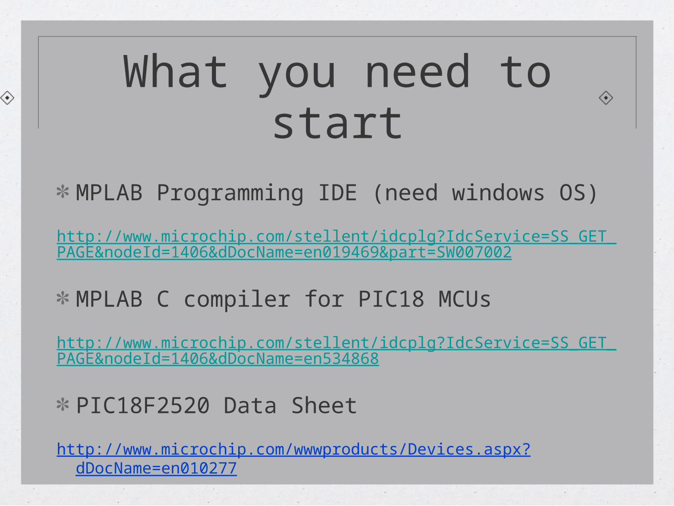
What you need to start
MPLAB Programming IDE (need windows OS)
http://www.microchip.com/stellent/idcplg?IdcService=SS_GET_PAGE&nodeId=1406&dDocName=en019469&part=SW007002
MPLAB C compiler for PIC18 MCUs
http://www.microchip.com/stellent/idcplg?IdcService=SS_GET_PAGE&nodeId=1406&dDocName=en534868
PIC18F2520 Data Sheet
http://www.microchip.com/wwwproducts/Devices.aspx?dDocName=en010277
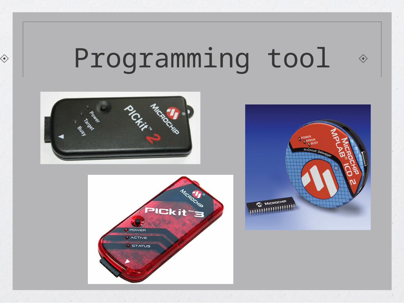
Programming tool
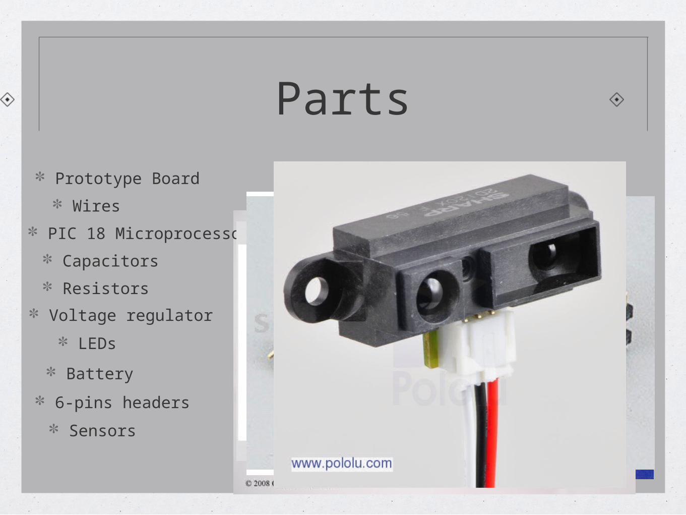
Parts
Prototype Board
Wires
PIC 18 Microprocessor
Capacitors
Resistors
Voltage regulator
LEDs
6-pins headers
Battery
Sensors
Parts
4Mhz Crystal
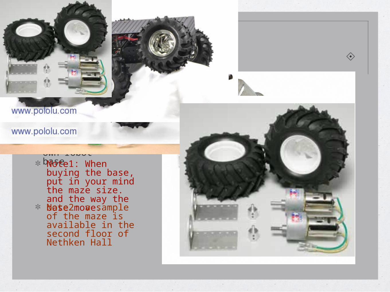
H-Bridge / Motor ControllerThe Base (Chassis)- Each group will bring its own robot base.Note1: When buying the base, put in your mind the maze size. and the way the base move.Note2: a sample of the maze is available in the second floor of Nethken Hall
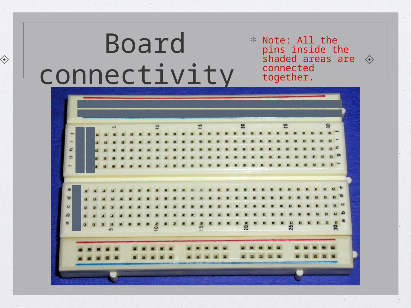
Board connectivity
Note: All the pins inside the shaded areas are connected together.
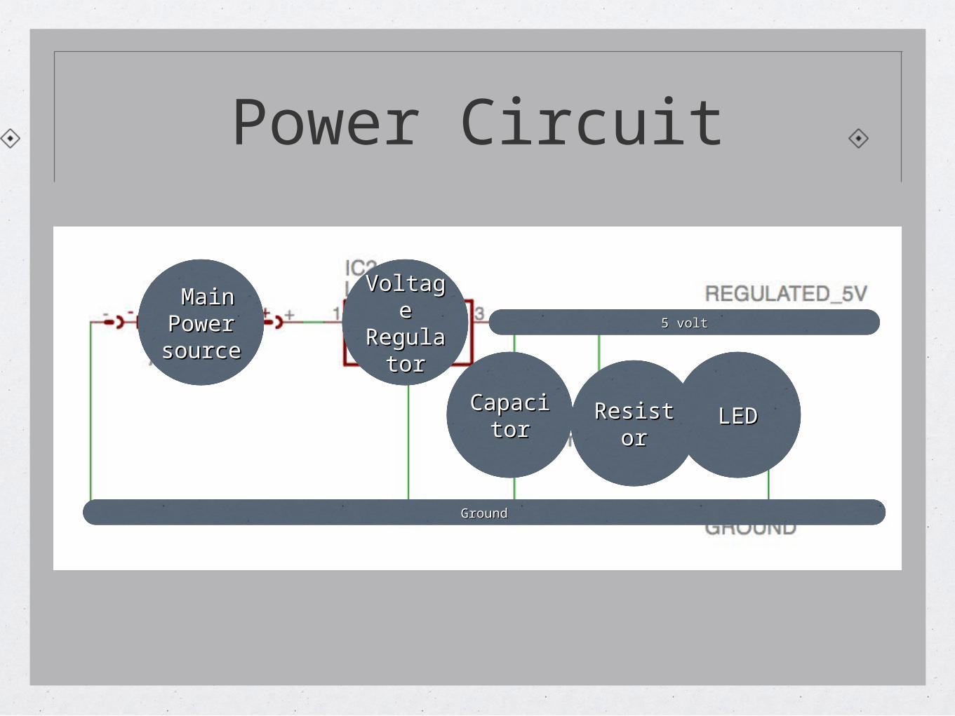
Power Circuit
Voltage Voltage RegulatRegulat
oror
Main Main Power Power sourcesource
CapacitCapacitoror
ResistoResistorr
LEDLED
5 volt5 volt
GroundGround
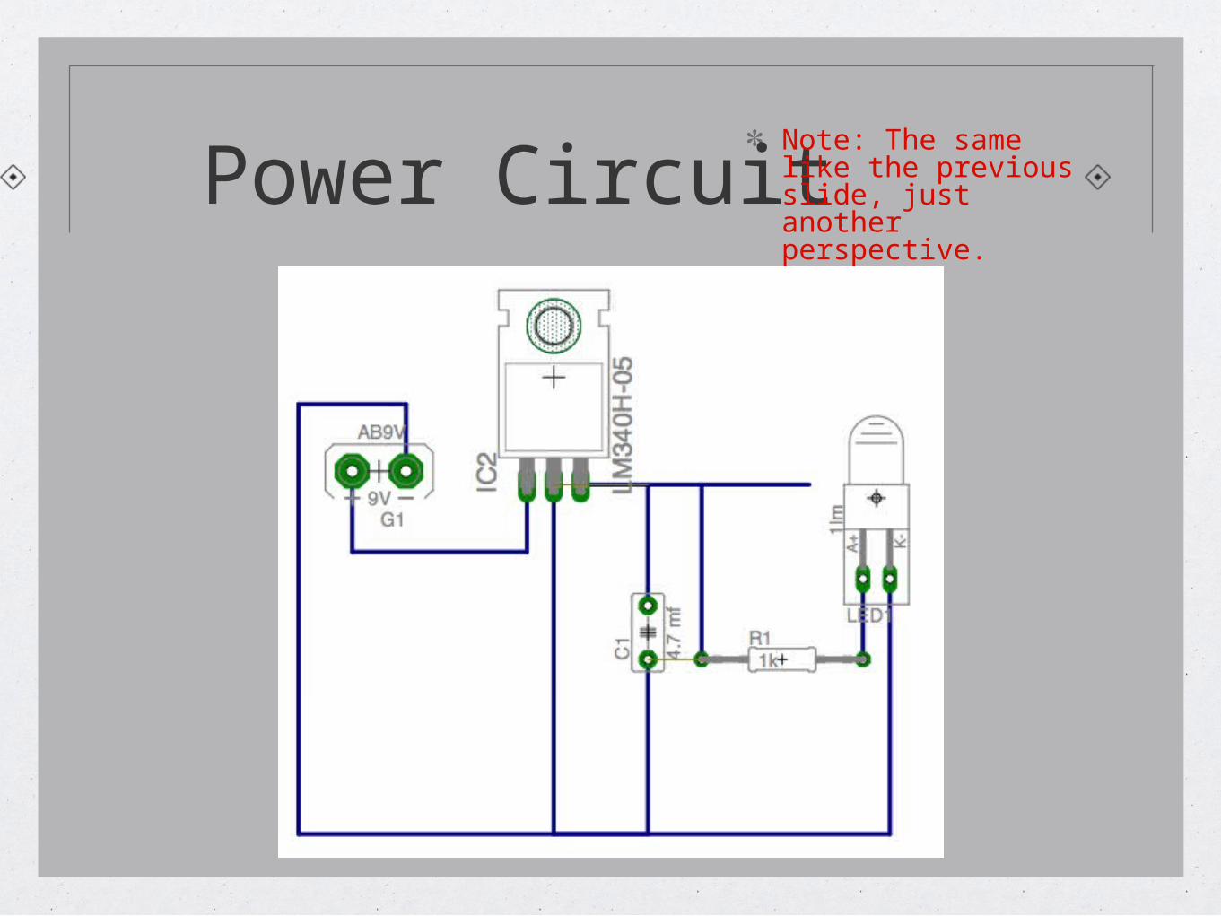
Power CircuitNote: The same like the previous slide, just another perspective.
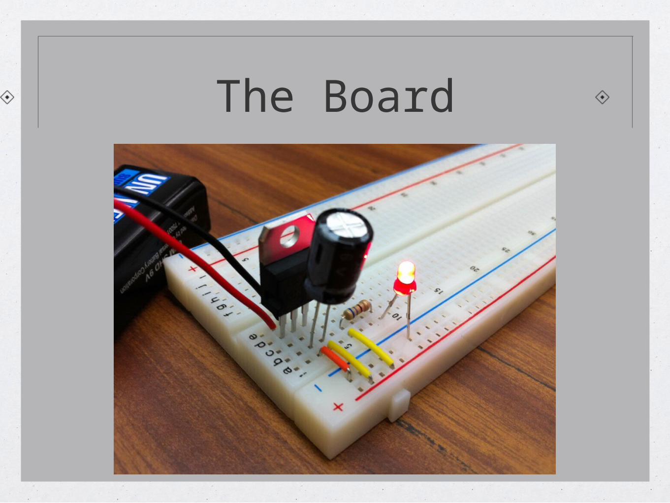
The Board
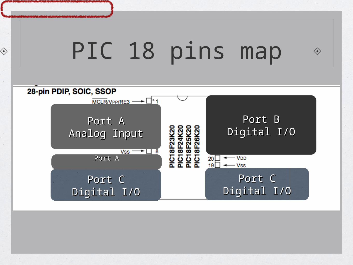
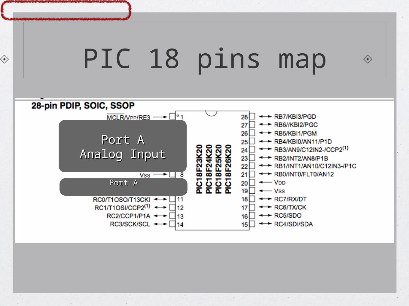
PIC 18 pins map
Port APort AAnalog InputAnalog Input
Port CPort CDigital I/ODigital I/O
Port CPort CDigital I/ODigital I/O
Port BPort BDigital I/ODigital I/O
Port APort A
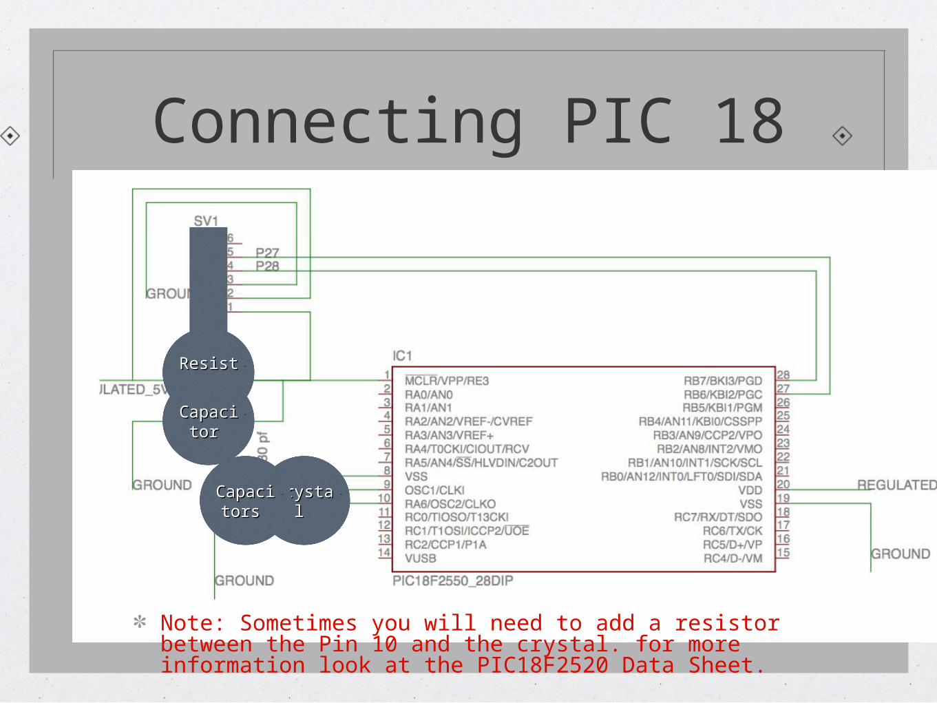
Connecting PIC 18
ResistoResistor r
CapacitCapacitor or
Crystal Crystal CapacitCapacitors ors
Note: Sometimes you will need to add a resistor between the Pin 10 and the crystal. for more information look at the PIC18F2520 Data Sheet.
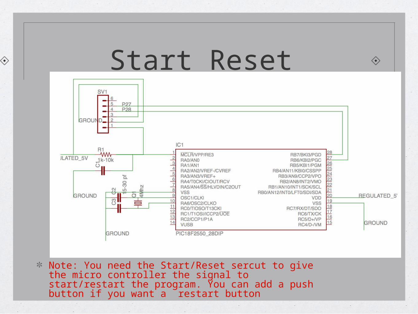
Start Reset
Note: You need the Start/Reset sercut to give the micro controller the signal to start/restart the program. You can add a push button if you want a restart button
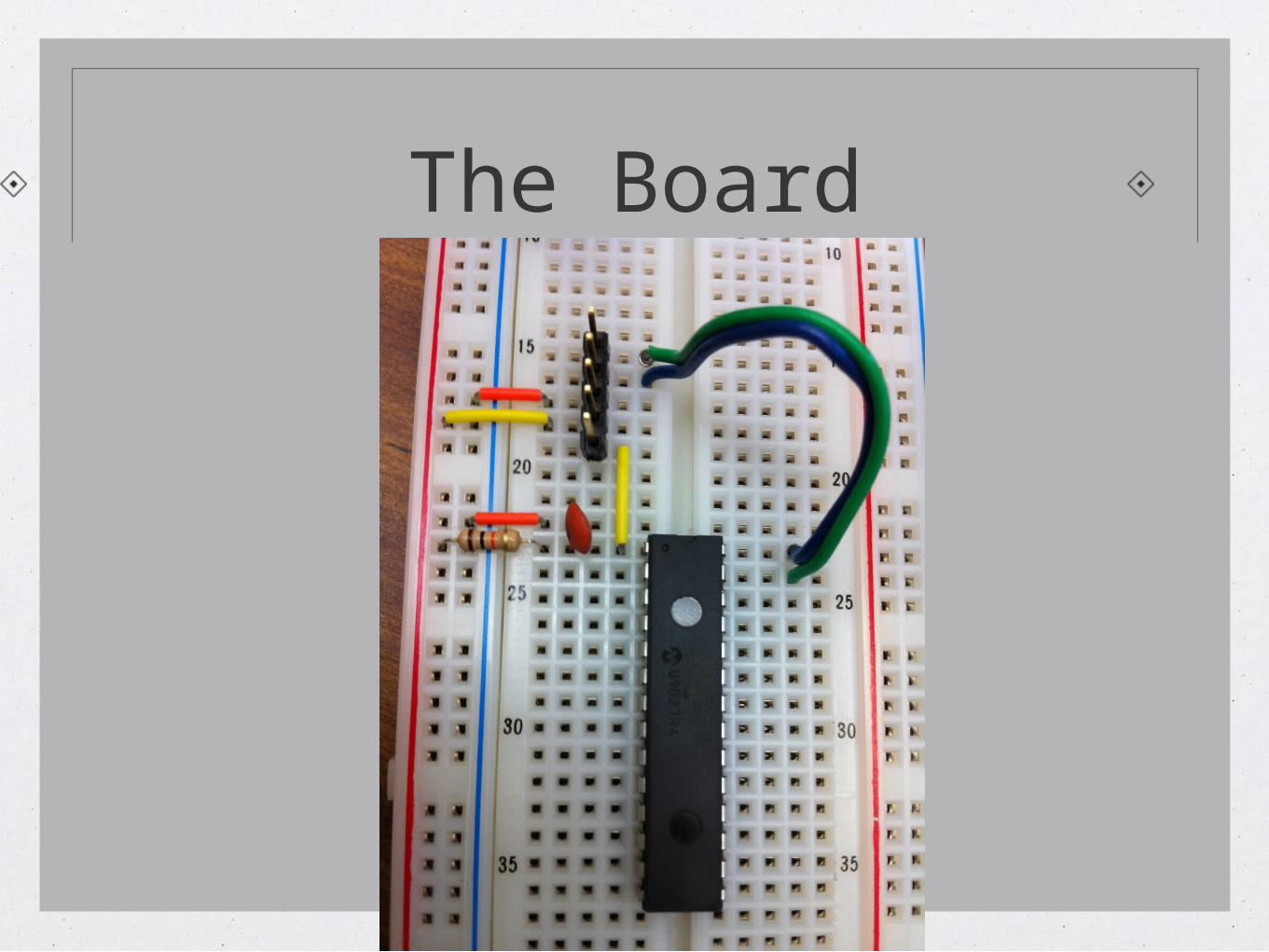
The Board

The H-Bridge
Why do we need the H-bridge ?
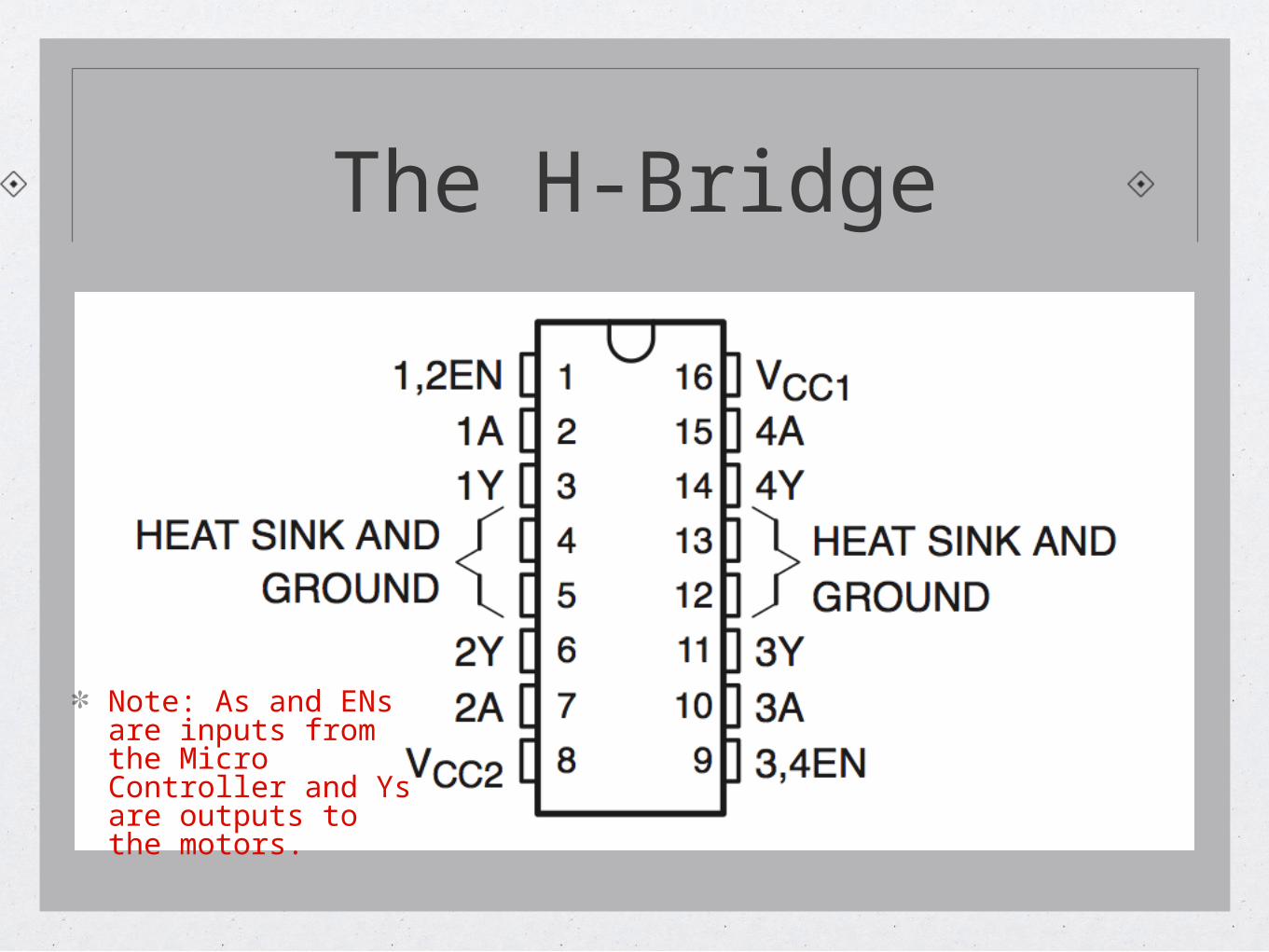
The H-Bridge
Note: As and ENs are inputs from the Micro Controller and Ys are outputs to the motors.
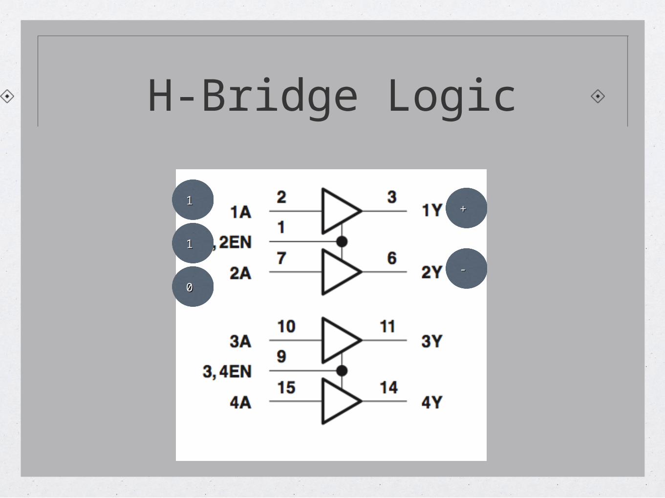
H-Bridge Logic
1 1
1 1
0 0
+ +
- -
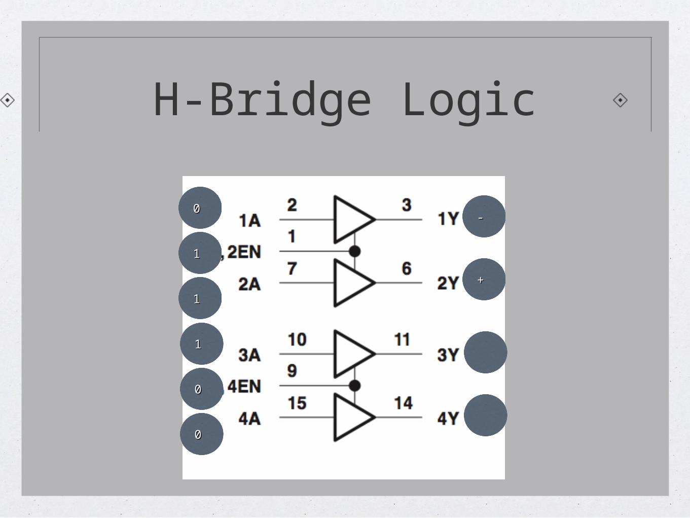
H-Bridge Logic
1 1
0 0
1 1
- -
+ +
0 0
1 1
0 0
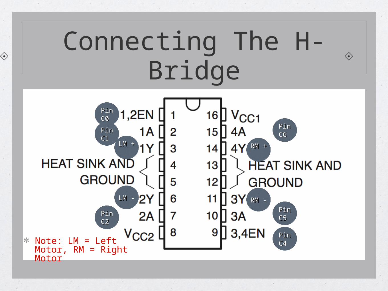
Connecting The H-Bridge
Pin Pin C0 C0
Pin Pin C1 C1
Pin Pin C2 C2
Pin Pin C4 C4
Pin Pin C6 C6
Pin Pin C5 C5
LM LM + +
LM - LM -
RM RM + +
RM - RM -
Note: LM = Left Motor, RM = Right Motor
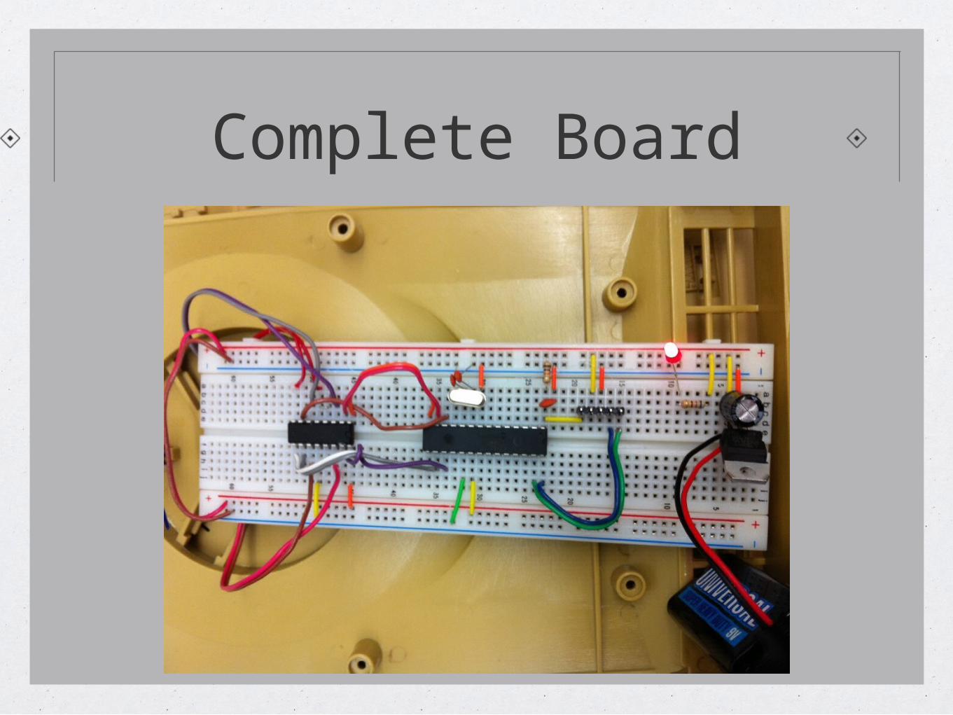
Complete Board
What You Learned
Robot requirements (Softwares and Hardwares)
How to make the power circuit
How to connect your PIC18 chip
How to connect the H-Bridge
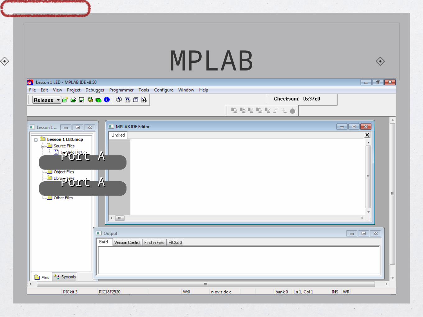
MPLAB
Port APort A
Port APort A
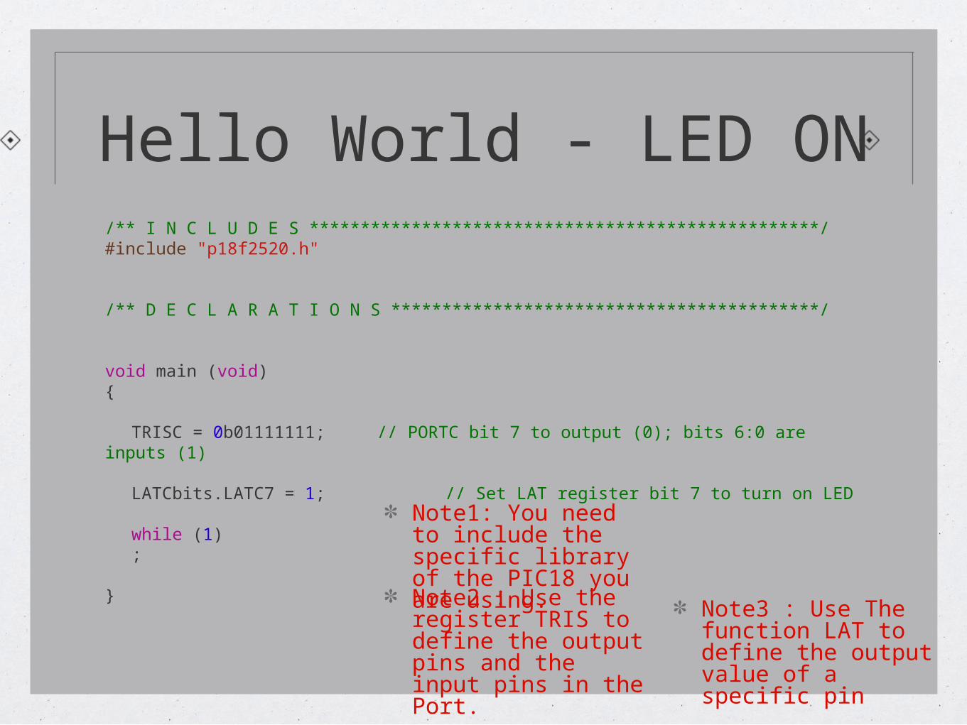
Hello World - LED ON/** I N C L U D E S **************************************************/#include "p18f2520.h"
/** D E C L A R A T I O N S ******************************************/
void main (void){
TRISC = 0b01111111; // PORTC bit 7 to output (0); bits 6:0 are inputs (1)
LATCbits.LATC7 = 1; // Set LAT register bit 7 to turn on LED
while (1);
}
Note1: You need to include the specific library of the PIC18 you are using.Note2 : Use the register TRIS to define the output pins and the input pins in the Port.
Note3 : Use The function LAT to define the output value of a specific pin
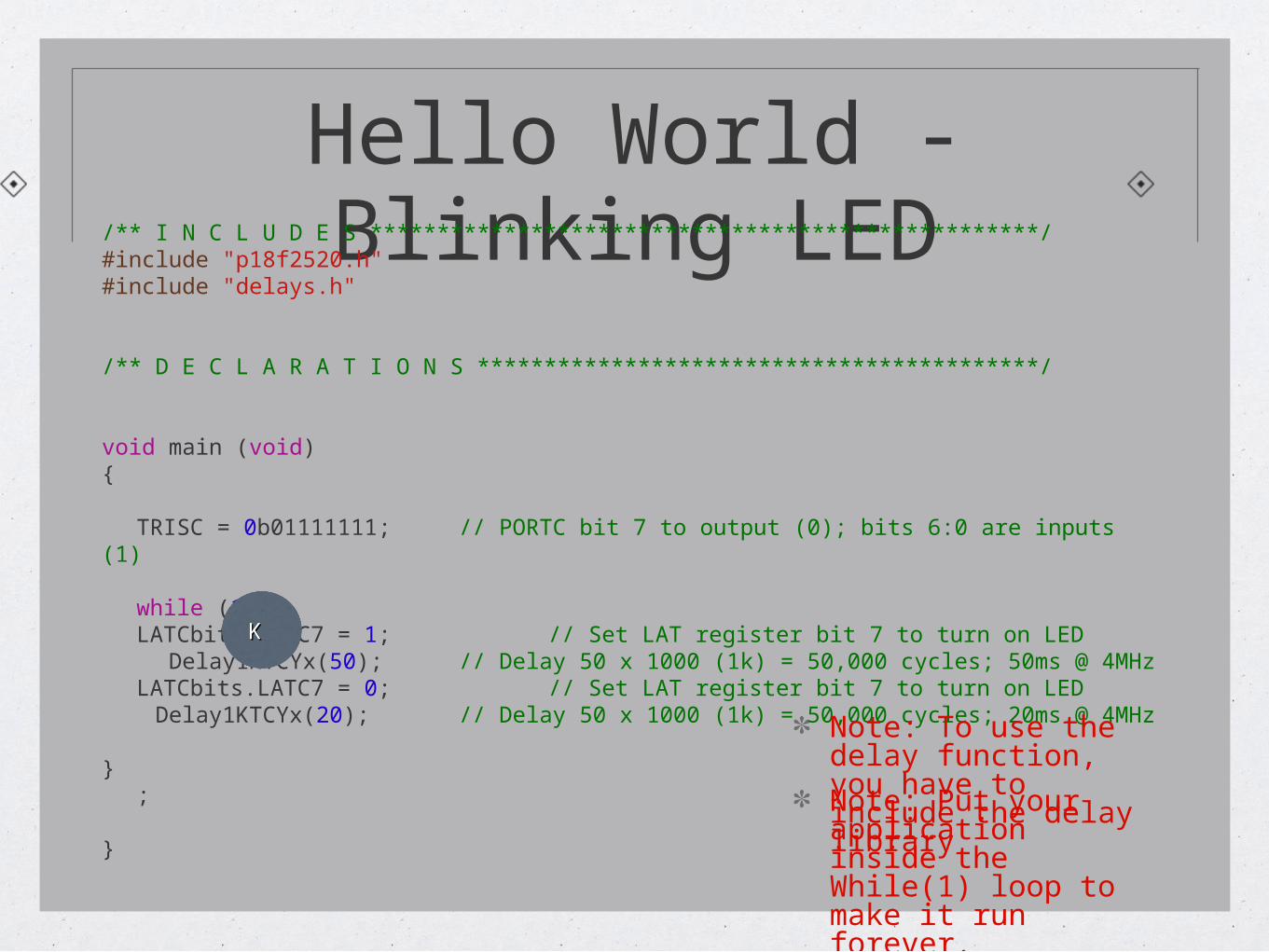
Hello World - Blinking LED/** I N C L U D E S **************************************************/
#include "p18f2520.h"#include "delays.h"
/** D E C L A R A T I O N S ******************************************/
void main (void){
TRISC = 0b01111111; // PORTC bit 7 to output (0); bits 6:0 are inputs (1)
while (1){LATCbits.LATC7 = 1; // Set LAT register bit 7 to turn on LED
Delay1KTCYx(50); // Delay 50 x 1000 (1k) = 50,000 cycles; 50ms @ 4MHzLATCbits.LATC7 = 0; // Set LAT register bit 7 to turn on LED
Delay1KTCYx(20); // Delay 50 x 1000 (1k) = 50,000 cycles; 20ms @ 4MHz
};
}
K K
Note: To use the delay function, you have to include the delay libraryNote: Put your application inside the While(1) loop to make it run forever.
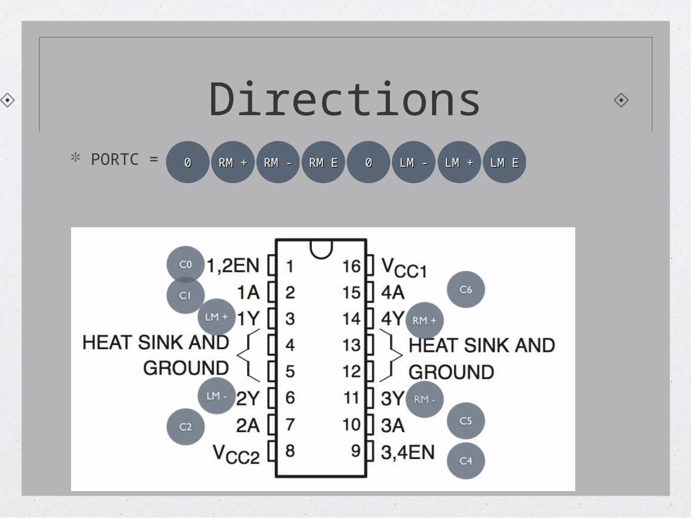
DirectionsC7 C7 C6 C6 C5 C5 C4 C4 C3 C3 C2 C2 C1 C1 C0C0PORTC = 00
RM RM + + RM - RM - RM E RM E 00 LM - LM - LM LM
+ + LM ELM E
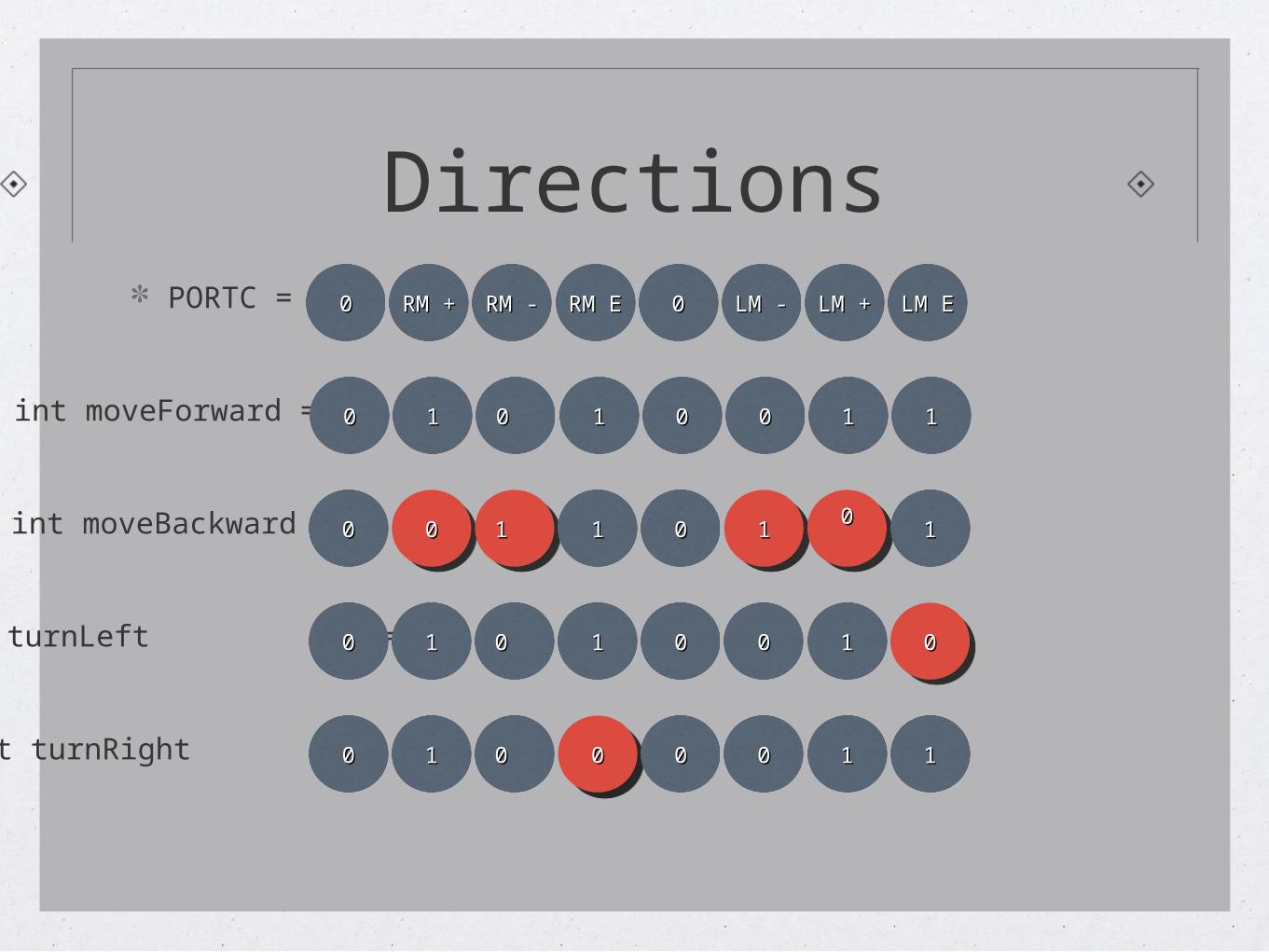
DirectionsPORTC = 00
RM RM + + RM - RM - RM E RM E 00 LM - LM - LM LM
+ + LM ELM E
int moveForward = 00 11 0 0 11 00 00 11 11
int moveBackward = 00 0000 1 1 1 1 11 00 11110000 11
int turnLeft = 00 11 0 0 11 00 00 11 0000
int turnRight = 00 11 0 0 0000 00 00 11 11
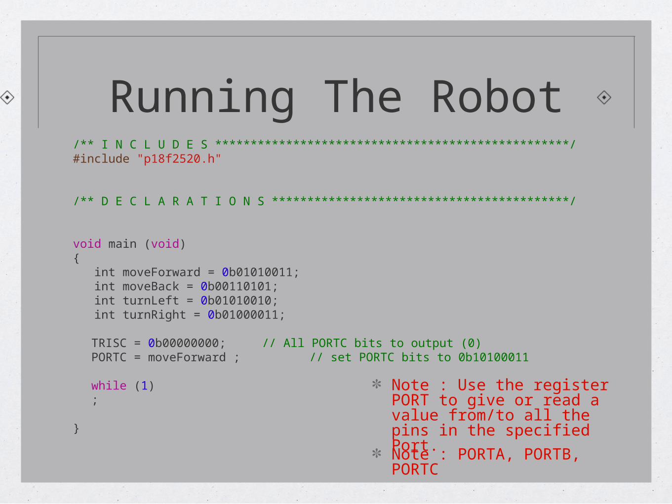
Running The Robot/** I N C L U D E S **************************************************/#include "p18f2520.h"
/** D E C L A R A T I O N S ******************************************/
void main (void){ int moveForward = 0b01010011; int moveBack = 0b00110101; int turnLeft = 0b01010010; int turnRight = 0b01000011;
TRISC = 0b00000000; // All PORTC bits to output (0)PORTC = moveForward ; // set PORTC bits to 0b10100011
while (1);
}
Note : Use the register PORT to give or read a value from/to all the pins in the specified Port.
Note : PORTA, PORTB, PORTC
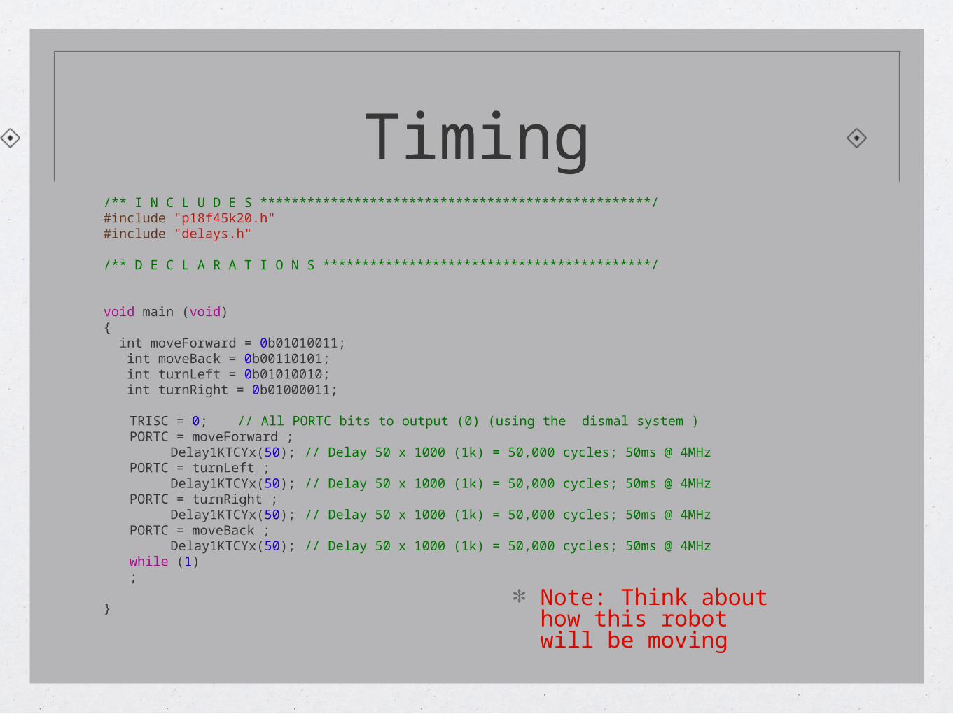
Timing/** I N C L U D E S **************************************************/#include "p18f45k20.h"#include "delays.h"
/** D E C L A R A T I O N S ******************************************/
void main (void){ int moveForward = 0b01010011; int moveBack = 0b00110101; int turnLeft = 0b01010010; int turnRight = 0b01000011;
TRISC = 0; // All PORTC bits to output (0) (using the dismal system )PORTC = moveForward ;
Delay1KTCYx(50); // Delay 50 x 1000 (1k) = 50,000 cycles; 50ms @ 4MHzPORTC = turnLeft ;
Delay1KTCYx(50); // Delay 50 x 1000 (1k) = 50,000 cycles; 50ms @ 4MHzPORTC = turnRight ;
Delay1KTCYx(50); // Delay 50 x 1000 (1k) = 50,000 cycles; 50ms @ 4MHzPORTC = moveBack ;
Delay1KTCYx(50); // Delay 50 x 1000 (1k) = 50,000 cycles; 50ms @ 4MHzwhile (1);
}Note: Think about how this robot will be moving
What You Learned
How to start your first project
How to define the Input and the output ports
How to Time Control your output
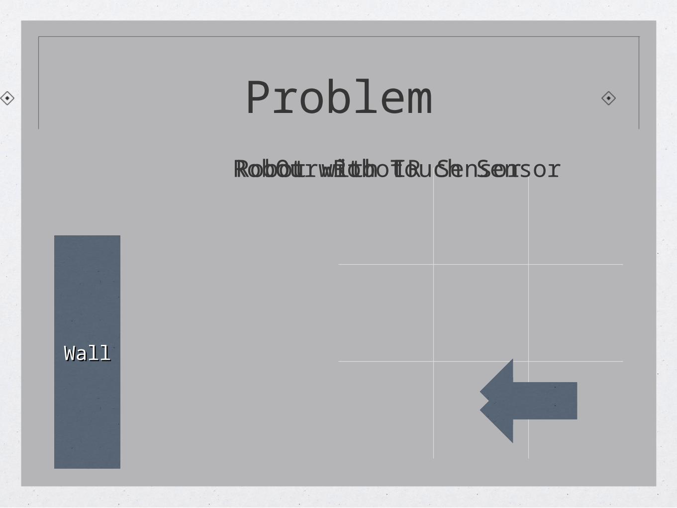
Problem
WallWall
Our RobotRobot with Touch SensorRobot with IR Sensor
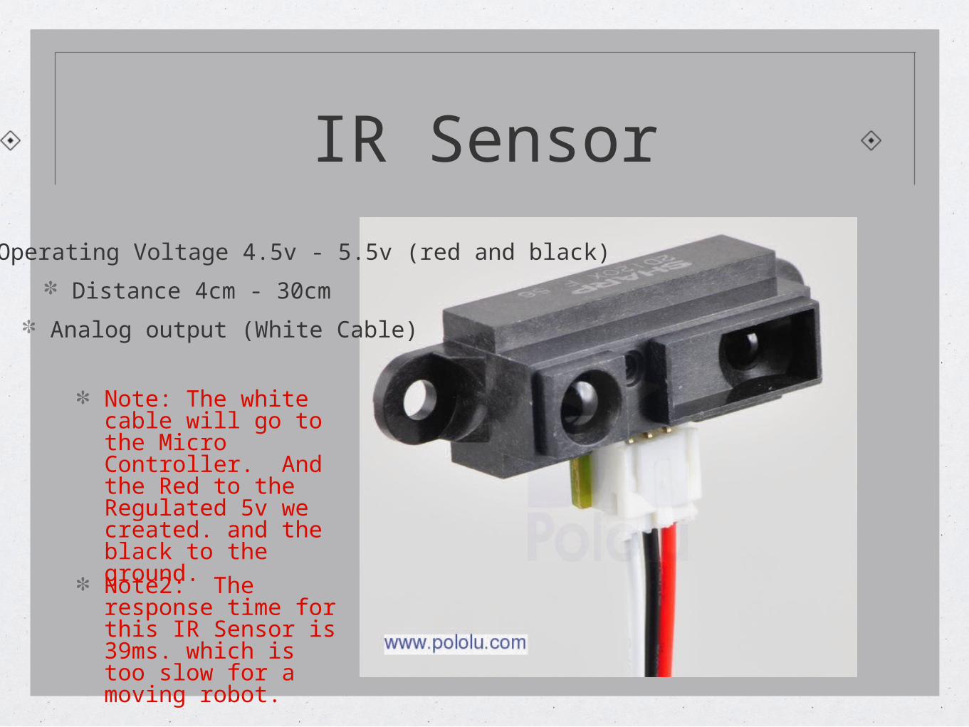
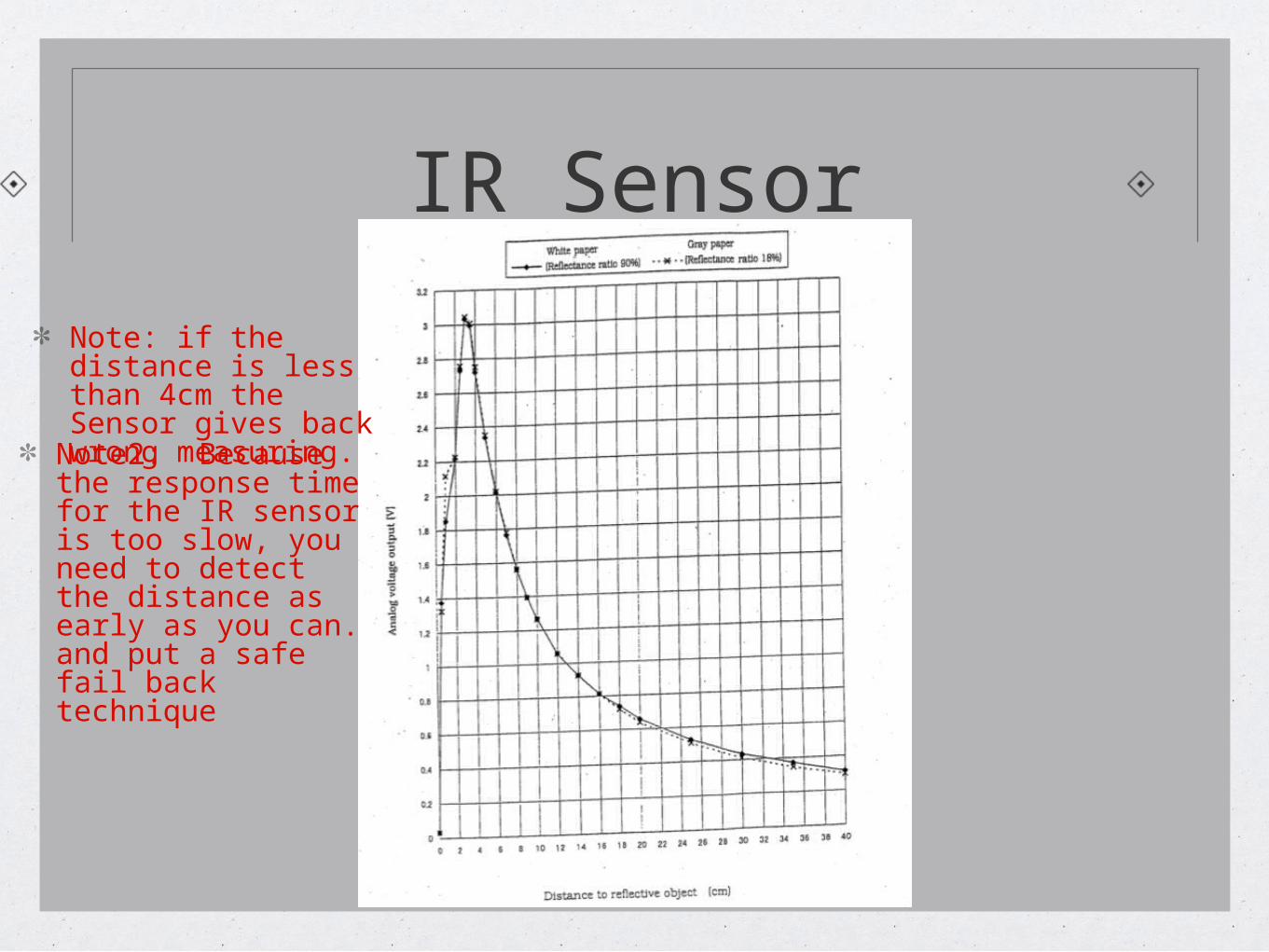
IR Sensor
Operating Voltage 4.5v - 5.5v (red and black)
Distance 4cm - 30cm
Analog output (White Cable)
Note: The white cable will go to the Micro Controller. And the Red to the Regulated 5v we created. and the black to the ground.
Note2: The response time for this IR Sensor is 39ms. which is too slow for a moving robot.
IR Sensor
Note: if the distance is less than 4cm the Sensor gives back wrong measuring.
Note2: Because the response time for the IR sensor is too slow, you need to detect the distance as early as you can. and put a safe fail back technique
PIC 18 pins map
Port APort AAnalog InputAnalog Input
Port APort A
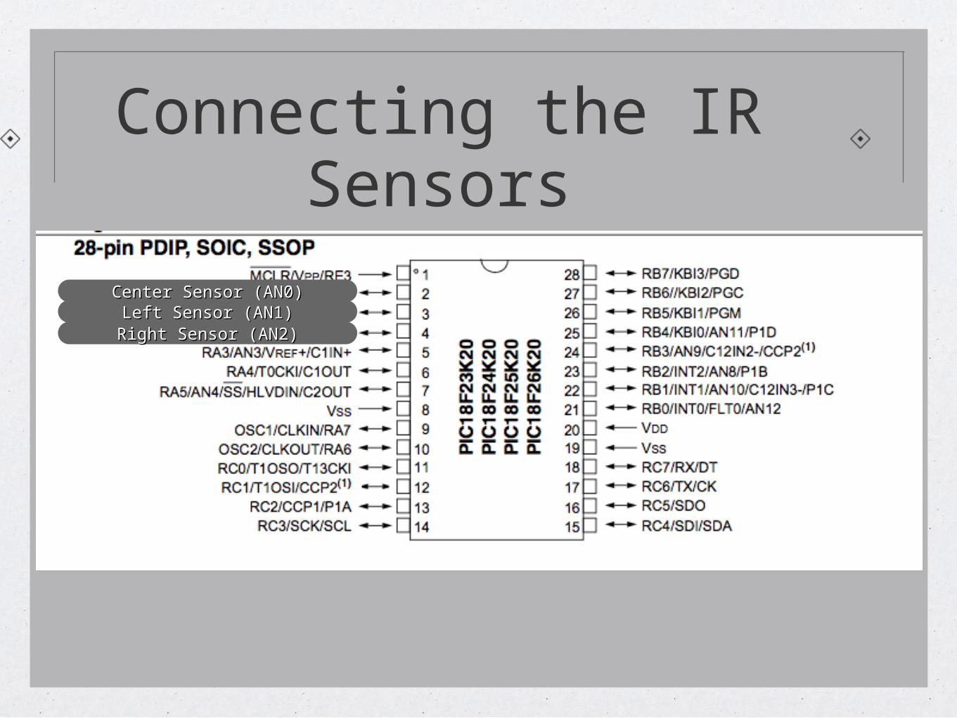
Connecting the IR Sensors
Center Sensor (AN0)Center Sensor (AN0)Left Sensor (AN1)Left Sensor (AN1)
Right Sensor (AN2)Right Sensor (AN2)
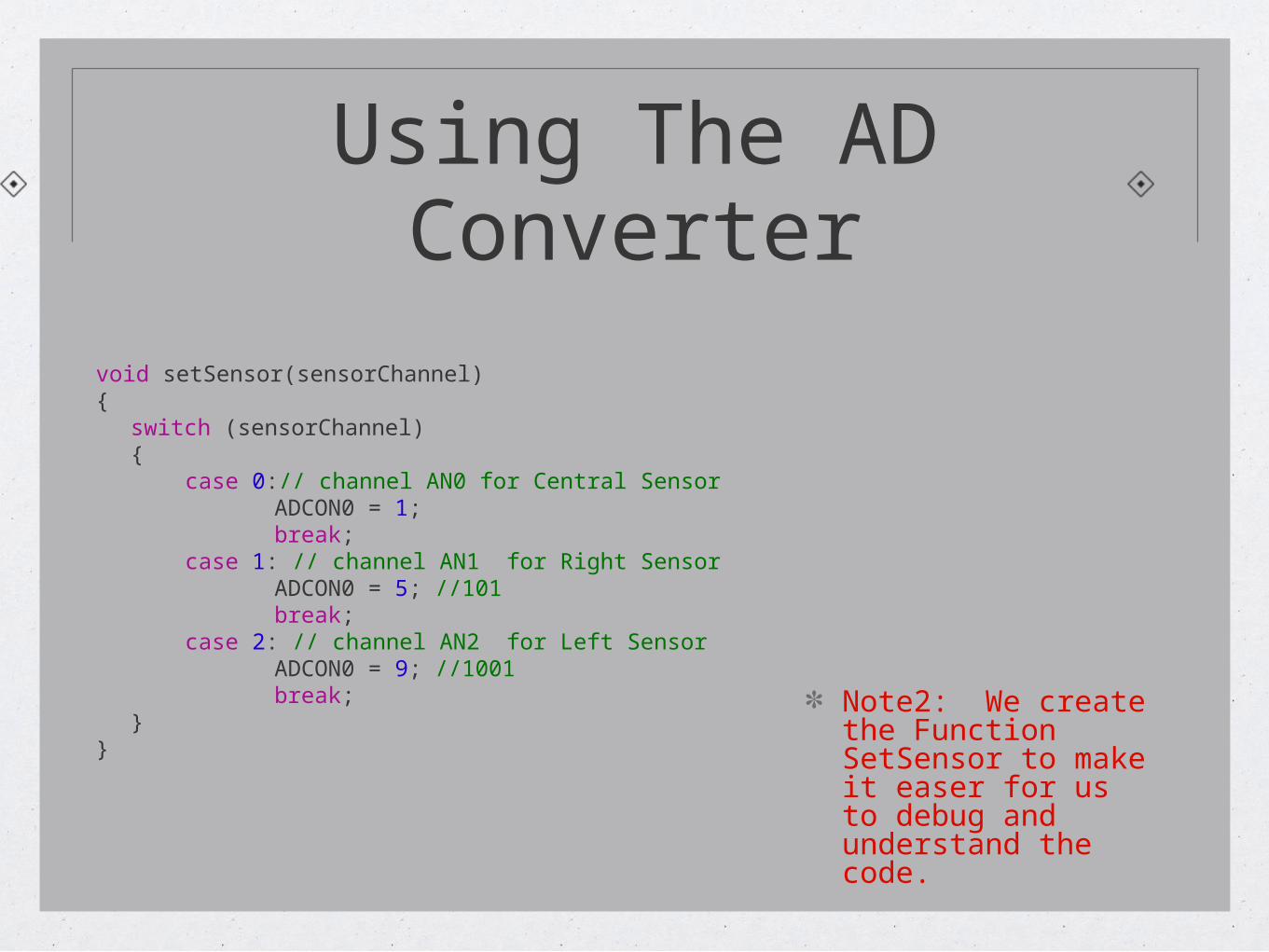
Using The AD Converter
void setSensor(sensorChannel){
switch (sensorChannel){
case 0:// channel AN0 for Central SensorADCON0 = 1;break;
case 1: // channel AN1 for Right SensorADCON0 = 5; //101break;
case 2: // channel AN2 for Left SensorADCON0 = 9; //1001break;
}}
Note2: We create the Function SetSensor to make it easer for us to debug and understand the code.
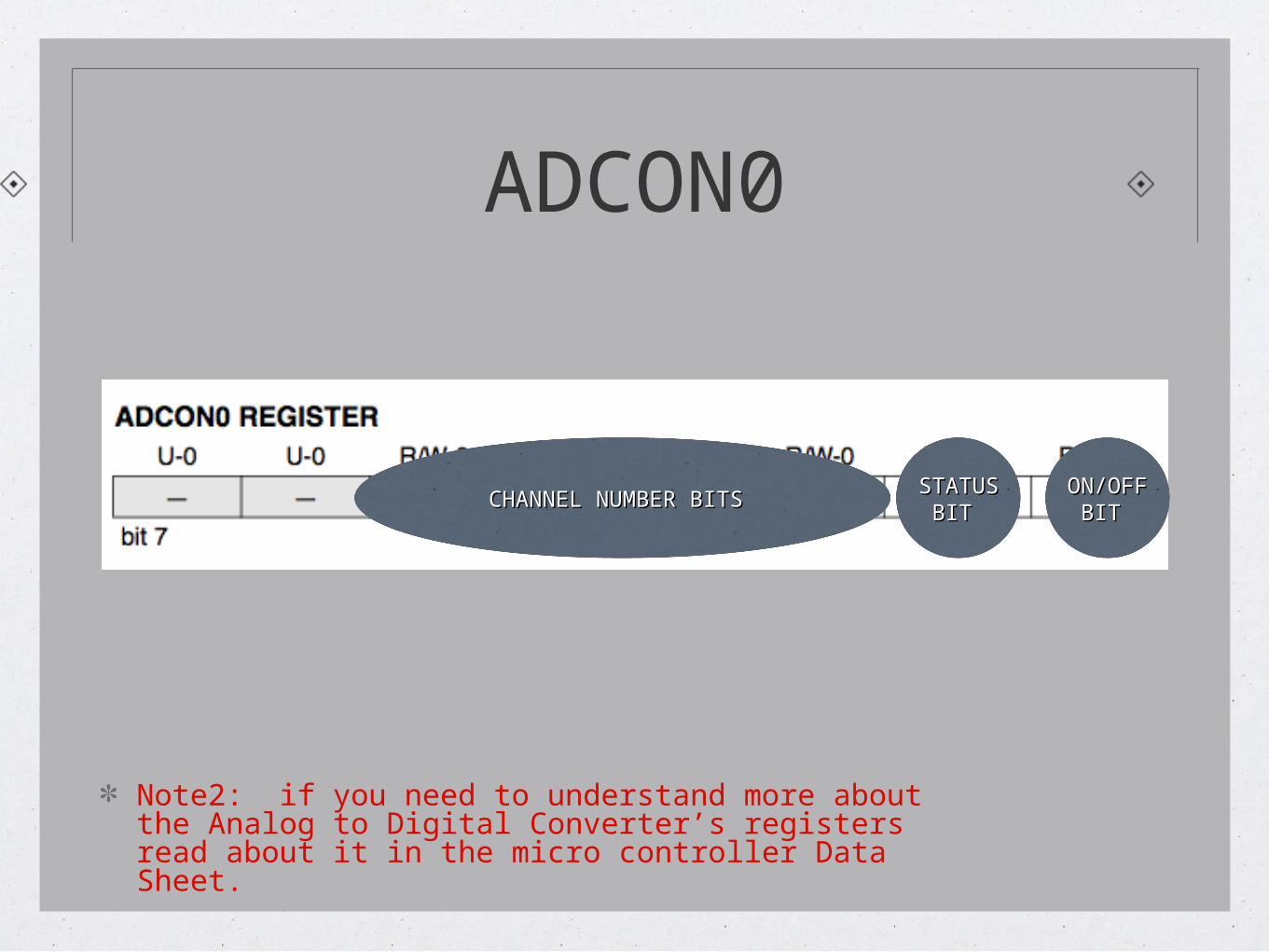
ADCON0
CHANNEL NUMBER BITS CHANNEL NUMBER BITS STATUS STATUS BIT BIT
ON/OFF ON/OFF BIT BIT
Note2: if you need to understand more about the Analog to Digital Converter’s registers read about it in the micro controller Data Sheet.
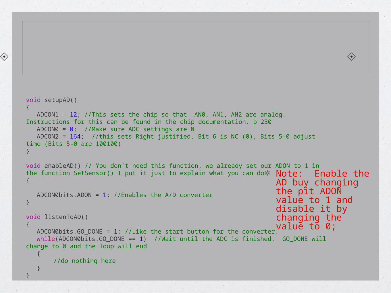
void setupAD(){
ADCON1 = 12; //This sets the chip so that AN0, AN1, AN2 are analog. Instructions for this can be found in the chip documentation. p 230
ADCON0 = 0; //Make sure ADC settings are 0ADCON2 = 164; //this sets Right justified. Bit 6 is NC (0), Bits 5-0 adjust time (Bits 5-0 are
100100)}
void enableAD() // You don’t need this function, we already set our ADON to 1 in the function SetSensor() I put it just to explain what you can do. {
ADCON0bits.ADON = 1; //Enables the A/D converter}
void listenToAD(){
ADCON0bits.GO_DONE = 1; //Like the start button for the converter. while(ADCON0bits.GO_DONE == 1) //Wait until the ADC is finished. GO_DONE will change to 0
and the loop will end{
//do nothing here}
}
Note: Enable the AD buy changing the pit ADON value to 1 and disable it by changing the value to 0;
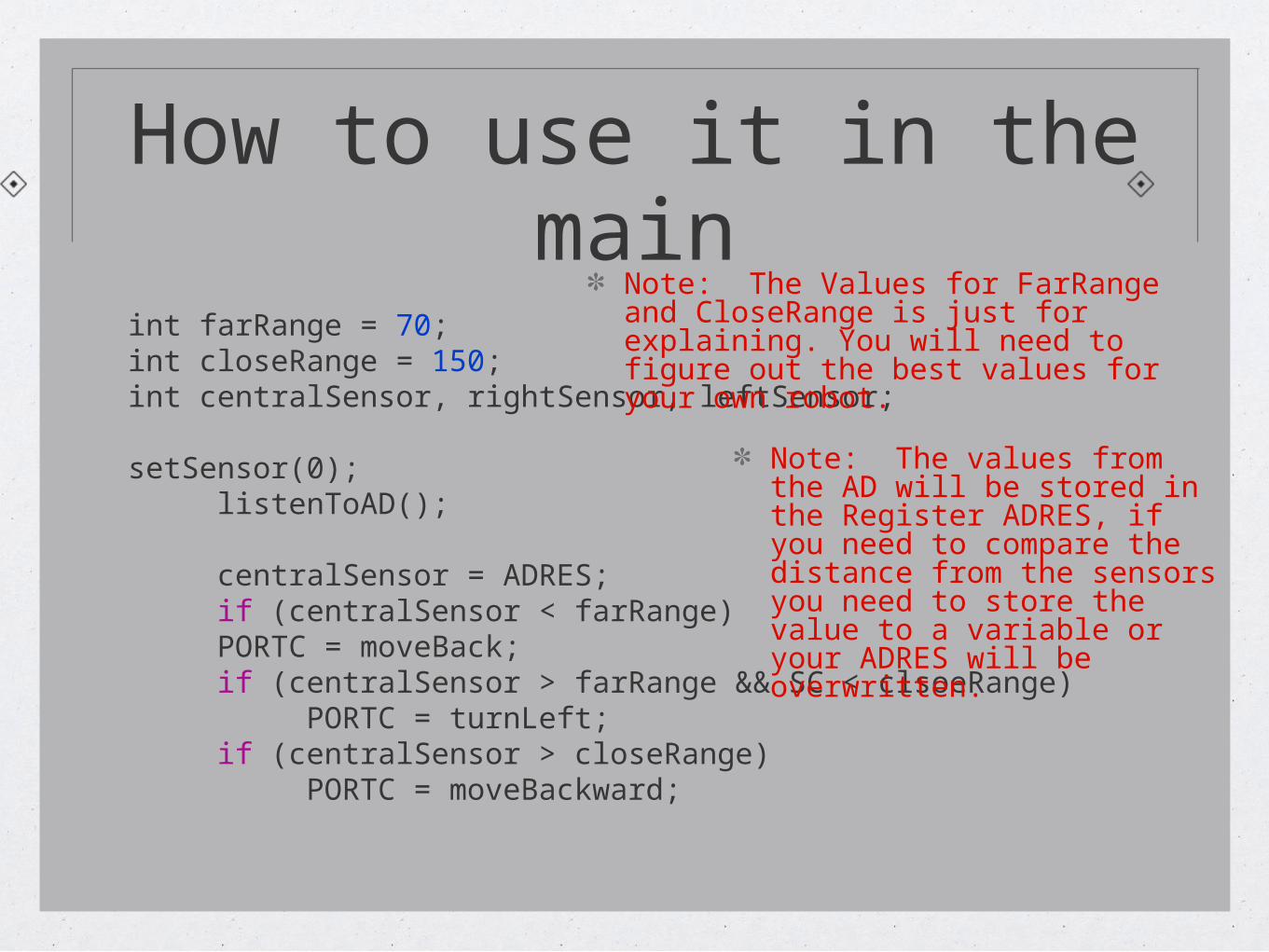
How to use it in the main
int farRange = 70;int closeRange = 150; int centralSensor, rightSensor, leftSensor;
setSensor(0);listenToAD();
centralSensor = ADRES;if (centralSensor < farRange)PORTC = moveBack;if (centralSensor > farRange && SC < clsoeRange) PORTC = turnLeft;
if (centralSensor > closeRange) PORTC = moveBackward;
Note: The Values for FarRange and CloseRange is just for explaining. You will need to figure out the best values for your own robot.
Note: The values from the AD will be stored in the Register ADRES, if you need to compare the distance from the sensors you need to store the value to a variable or your ADRES will be overwritten.
What You learned
The Usage of Sensors
How to use Analog IR sensor
Making The right dictionNote: The Code I provided is not meant to be running 100%, it is explanatory code ONLY.
You will need to define your functions and variables correctly.

SPECIAL THANKS
Robotic Club Advisor
Dr. Ben Choi
Robotic Club Vise President
James Hurst
Our FaceBook Group : Louisiana Tech Robotic Club