introducing a new sensor for in-mixer air … a new sensor for in-mixer air volume measurement...
TRANSCRIPT

INTRODUCING A NEW SENSOR FOR IN-MIXER AIR VOLUME
MEASUREMENT
Nathan Tregger, PhD, W.R. Grace, Cambridge, MA
Douglas Loose, CiDRA Inc., Wallingford, CT
Timothy Durning, PE, W.R. Grace, Cambridge, MA
Ara Jeknavorian, PhD, W.R. Grace, Cambridge, MA
Ed Mansky, W.R. Grace, Cambridge, MA
Stephen Klaus, W.R. Grace, Cambridge, MA
ABSTRACT
It is well established that freeze-thaw durable concrete requires proper levels
of entrained air. As an inexpensive mix component, entrained air can also
improve concrete workability. Despite well over fifty years of commercial
production of air entrained concrete, the high batch to batch variability of air
content is one of the concrete industry’s most vexing quality control problems.
A sensor has recently been developed that can accurately determine the air
volume in concrete based on the impact that air bubbles have on the
propagation of low-frequency acoustic waves. This sensor provides
continuous, real-time air measurements during the entire mixing process for
stationary wall mixers. Knowing the air content in each batch during the
mixing process allows producers to adjust practices to dramatically reduce
batch to batch air volume variability. This paper will present data developed
in a laboratory environment as well as from several precast producers that
document the correlation between the acoustically determined air content and
that determined via the pressure method in fresh concrete per ASTM C231.
Keywords: Air, Pressure meter, Real-time measurement

Tregger, Loose, Durning, Jeknavorian, Mansky, Klaus 2013 PCI/NBC
2
INTRODUCTION
Well-controlled air-entrainment in concrete has been universally accepted as a reliable means
for enhancing the ability of concrete to resist the potentially destructive effect of repeated
cycles of freezing and thawing, as well as altering the workability and yield of cementitious
mixtures. Air-entrainment should be mandatory when concrete is to be exposed to such harsh
environments, particularly when chemical deicers are being used, as on pavements and
bridge decks1. Indeed, the ACI 318 building code mandates different levels of air content
based upon the severity of the environment that the concrete will be exposed to in service2.
To achieve different levels of air content, a wide range of surface-active materials have been
reported as suitable air-entraining admixtures, which Whiting and Nagi3 have classified into
five broad categories with general performance characteristics for each group. These
admixtures are designed to entrain air in the form of small, spherical, discrete air-voids or
bubbles dispersed throughout the mixture, in sufficient volume and spatial distribution to
provide freeze-thaw durability. A material conforming to the requirements in ASTM C 260
Standard Specification for Air-Entraining Admixtures for Concrete can be classified as an
air-entraining admixture4.
Though air-entrainment in concrete is a well established practice, the amount and form of the
air-entrained in concrete can be influenced by some thirty factors which include: (1) the
concentration and type of the air-entraining admixture and its influence on surface tension;
(2) the use of other admixtures in the concrete mixture; (2) the fineness and composition of
cement and supplementary cementitious materials; (3) the amount of mixing energy (time
and shear rate); (4) the flow and slump of mortar or concrete mixture; (5) the temperature,
water-cement ratio, and water content of the mixture; and (6) the gradation of the fine and
coarse aggregates3,5
. Every one of these thirty or more factors rarely stays constant
throughout the day, and in fact one or more factors may often change from batch to batch.
The end result is variability in batch to batch air contents that can routinely result in
significant material and time inefficiencies, and occasionally durability or structural
concerns.
Up until now, the only methods available for determining the air content in plastic concrete
(e.g. ASTM C231, ASTM C173, ASTM C138) require removal of a sample of concrete from
the mixer, and consume 5 to 10 minutes to carry out. In a precast plant where mixer output is
a key determinant of productivity, adding 5 to 10 minutes on any significant percentage of
the batches can be quite costly. In addition, many precast producers have no ability to sample
concrete prior to discharging the batch out of the mixer. If the air is outside specification
limits, the batch must get discarded or re-directed for use in a lower value application.
Adjustments are then made on the next batch. However, these adjustments may be futile as
the next batch may already have changed. This is analogous to shooting at a moving target
based solely upon where it was in the past.
The novel air measurement system evaluated in this study presents a dramatic improvement
on the situation described above. The system gives the concrete producer knowledge in real-
time of the air contents in the concrete within the mixer as it builds through the mix cycle.

Tregger, Loose, Durning, Jeknavorian, Mansky, Klaus 2013 PCI/NBC
3
Producers with this device should be able to adjust air entraining agent (AEA) doses and
mixing conditions such that every batch is within specification without undue external testing
delays.
BACKGROUND
The ability to measure the volumetric air content of industrial liquids and slurries flowing
through a pipe using a passive acoustic-based instrument has been commercially available for
several years6. Using the relation between the speed of sound in a two-phase mixture and the
volumetric phase fraction is well known in the case where the wavelength of sound is
significantly larger than any process in-homogeneities, such as bubbles7.
The acoustic-based measurement of process aeration covers several orders of magnitude,
from 0.01% to 20% (by volume), and is therefore universally applicable to a wide variation
of process conditions. This technology is used in many industrial applications where aeration
must be controlled to a desirable level or must be avoided altogether. There are other
applications where aeration negatively impacts process control by affecting other types of
meters. Examples of these include:
Tank level/foam control in agro processing applications
Entrained air in the thin stock flow to a paper machine’s headbox6
Entrained air in filling stations for domestic household products
Dissolving carbon dioxide in beverages
Errors in consistency measurement of paper stock8
Errors in Coriolis determined volume flow and density as a result of product aeration9
Errors in custody transfer metering resulting from product flashing or aeration
A new implementation of the same technology enables air content measurement of liquids
and slurries not constrained within a pipe, such as in stationary-wall concrete mixers.
SPEED OF SOUND IN AERATED CONCRETE
Wood’s model10
, for the speed of sound in bubbly liquids describes the acoustic properties of
a two-phase mixture where the frequency is much lower than the lowest bubble resonance
frequency. This model has been shown to accurately describe the speed of sound in slurries
and gas-bearing sediment11
, therefore is also a good basis in the case of plastic, aerated
concrete.

Tregger, Loose, Durning, Jeknavorian, Mansky, Klaus 2013 PCI/NBC
4
Concrete is commonly mixed in a stationary-wall mixer, and in this case will have a static
pressure just slightly above atmospheric, always having some level of entrained aeration.
Under these conditions and assuming isothermal conditions, the compressibility of the air
phase is orders of magnitude larger than the compressibility of the slurry phase, and Wood’s
equation reduces to Equation 1:
1
aPc (1)
where, c is the speed of sound, Pa is the absolute static pressure, ϕ is the volumetric fraction
of air, and ρ is the density of the concrete slurry.
Wood’s simplified model is only dependent on the static pressure and slurry density. Both of
these properties are relatively consistent for most concrete mixing applications, and the small
variations that do exist can generally be ignored. Figure 1 illustrates the relation between the
mixture sound speed and air content for typical concrete slurry.
Figure 1: Wood's simplified model for plastic concrete
2 3 4 5 6 7 8 9 1080
100
120
140
160
180
200
Air content [%]
Speed o
f sound [ft/s
]

Tregger, Loose, Durning, Jeknavorian, Mansky, Klaus 2013 PCI/NBC
5
SPEED OF SOUND IN AERATED CONCRETE
To determine the speed that sound propagates through plastic concrete, the time-of-flight
between a sound source and a sound receiver, spatially separated by a known distance, is
measured. The sound source consists of a baffled piston driven at a relatively low-frequency,
well below the lowest bubble resonance frequency. A temporal cross-correlation between the
source drive and receiver signals yields the propagation time and therefore the speed of
sound.
Because a relatively low frequency sound is used, the sound waves are not directional but
rather propagate with near equal strength in all directions. Therefore the sensing surface of
the receiver can be located on the same plane as the source. This is important for use in a
concrete mixer since nothing can protrude into the mixer; otherwise interference with the
mixing paddles would occur. The source and receiver are packaged in a single probe which is
mounted through the floor or side wall of the mixer such that the face of the probe is just
flush with the inside mixer wall and is in contact with the concrete slurry as it is being mixed.
Additionally, the mechanical design of both the source and receiver must be such that they
will operate reliably in the abrasive environment inside a concrete mixer. Figure 2 shows the
installed unit in the bottom of the laboratory-scale pan mixer for this study.
Figure 2: Sensor installed in laboratory pan mixer
EXPERIMENTAL APPROACH
In this initial study, air contents obtained by the ASTM C231 pressure meter were compared
to measurements acquired by the acoustic sensor. Two mix designs were considered: a high-
range water-reducing concrete (HRC) mix with a target slump of 6-8 in (150-200 mm); and a
self-consolidating concrete (SCC) mix with a target slump flow of 25-27 in (640-690 mm).

Tregger, Loose, Durning, Jeknavorian, Mansky, Klaus 2013 PCI/NBC
6
These mix designs are common to the precast industry. With the slump or flow held constant,
three air ranges were targeted: 2-4%, 4-6% and 7-9%. Air targets were achieved by adjusting
the air-entraining admixture (AEA) dosage. For each mix design, several mixes were
repeated to validate performance.
MIX DESIGN AND PROTOCOL
The mix designs for the HRC and the SCC are given in Table 1. The water-to-cement (w/c)
was held constant between the two mixes while a polycarboxylate high-range water-reducer
(HRWR) was used to adjust slump. A planetary, lab-scale pan mixer was used to produce 1.4
ft3 (0.04 m
3) of concrete using the mix protocol in Table 2.
Table 1: Mix designs
HRC SCC
Cement [lb/yd3, kg/m
3] 625, 370 750, 450
Sand [lb/yd3, kg/m
3] 1450, 860 1450, 860
Stone [lb/yd3, kg/m
3] 1700, 1000 1450, 860
Water [lb/yd3, kg/m
3] 275, 160 330, 200
HRWR [oz/cwt, mL/100kg] 4.6, 230 5.5, 270
AEA [oz/cwt, mL/100kg] 0.10-1.0, 5-50 0.05-0.70, 2.5 - 35
Table 2: Mix protocol
Material addition Mix time and speed
Add stone, sand, water, AEA 1 minute at high speed
Add cement 1 minute at high speed
Add HRWR 2 minutes at high speed
None 2 minutes at semi-static speed
Measurements taken included: 1 slump or slump flow, 2 unit weights, 2 air-pot readings, 2
cylinders each for 1 or 3 day and 7 and 28 day compressive strengths. Two different
operators supplied the unit weights and pressure meter readings.
EXPERIMENTAL RESULTS
Tregger, Loose, Durning, Jeknavorian, Mansky, Klaus 2013 PCI/NBC
7
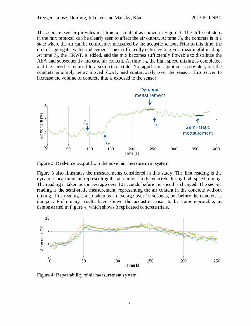
The acoustic sensor provides real-time air content as shown in Figure 3. The different steps
in the mix protocol can be clearly seen to affect the air output. At time T1, the concrete is in a
state where the air can be confidently measured by the acoustic sensor. Prior to this time, the
mix of aggregate, water and cement is not sufficiently cohesive to give a meaningful reading.
At time T2, the HRWR is added, and the mix becomes sufficiently flowable to distribute the
AEA and subsequently increase air content. At time T3, the high speed mixing is completed,
and the speed is reduced to a semi-static state. No significant agitation is provided, but the
concrete is simply being moved slowly and continuously over the sensor. This serves to
increase the volume of concrete that is exposed to the sensor.
Figure 3: Real-time output from the novel air measurement system
Figure 3 also illustrates the measurements considered in this study. The first reading is the
dynamic measurement, representing the air content in the concrete during high speed mixing.
The reading is taken as the average over 10 seconds before the speed is changed. The second
reading is the semi-static measurement, representing the air content in the concrete without
mixing. This reading is also taken as an average over 10 seconds, but before the concrete is
dumped. Preliminary results have shown the acoustic sensor to be quite repeatable, as
demonstrated in Figure 4, which shows 3 replicated concrete trials.
Figure 4: Repeatability of air measurement system
0 50 100 150 200 250 300 350 4000
2
4
6
Time [s]
Air c
onte
nt [%
]
Dynamic
measurement
Semi-static
measurement
T3
T2
T1
0 50 100 150 200 2504
6
8
10
Time [s]
Air c
onte
nt [%
]

Tregger, Loose, Durning, Jeknavorian, Mansky, Klaus 2013 PCI/NBC
8
It is important to understand that external energy (i.e. mixing, pouring or rodding) can both
create and destroy air bubbles within a concrete mixture. Thus, depending on the concrete
system, when the mixing speed changes from high to semi-static, air can decrease (no energy
to maintain air) or stay the same (no energy to destroy air). This is demonstrated in Figure 5,
where both these scenarios are observed. For the top graph, the change from high to semi-
static occurs around 250 seconds and a decrease in air content can be seen. However, for the
bottom graph, the air content continues to increase even after a change to the semi-static
speed (again, around 250 seconds). A noticeable change in the oscillation of the sensor
output is observed as the mixing speed is changed. When the mixing blade moves past the
sensor at the semi-static mixing speed, it briefly uncovers the sensor, causing the output to
increase. As the concrete closes up over the sensor, the reading decreases.
Figure 5: Examples of changes in air due to changes in mixing speed
In Figure 6, the static and dynamic measurements are compared directly. In general, the
dynamic measurements tend to be higher than the static measurements (by an average of
about 1%). The cement content (which in this case represents the difference between HRC
and SCC) seems to have a small effect on the overall relationship.
0 50 100 150 200 250 300 350 4000
2
4
6
Time [s]
Air c
onte
nt [%
]
0 50 100 150 200 250 300 350 4000
5
10
15
Time [s]
Air c
onte
nt [%
]

Tregger, Loose, Durning, Jeknavorian, Mansky, Klaus 2013 PCI/NBC
9
Figure 6: Static versus dynamic measurements
Figure 7 shows the relationship between static measurements and the pressure meter readings
while Figure 8 shows the relationship between dynamic measurements and the pressure
meter readings. The pressure meter readings are the average of two readings obtained on the
same concrete at the same time by different operators. During this study, the median absolute
difference between pressure meter readings was ±0.3% air, while the maximum difference
was 2.2%. During the study, if the difference was more than 1.5% air, the pressure meters
were redone to validate. This occurred twice within the current study. In Figure 7, the
relationship is well-centered on y = x line, with a median absolute difference of ±0.44% air.
The dynamic reading, as expected based on Figure 6, is higher than the pressure meter, but
the slope of the regression line is practically parallel with the y = x line. The median absolute
difference for the dynamic measurement is ±0.69% air.
0 2 4 6 8 100
1
2
3
4
5
6
7
8
9
10
Cement [pcy]
625
750
Static measurement [%]
Dynam
ic m
easure
ment [%
]
r2 = 0.9
||med
= 0.98
m = 0.89
Slu
mp o
r flow
[in
]
0
10
20
30

Tregger, Loose, Durning, Jeknavorian, Mansky, Klaus 2013 PCI/NBC
10
Figure 7: Static measurements versus pressure meter readings
0 2 4 6 8 100
1
2
3
4
5
6
7
8
9
10
Cement [pcy]
625
750
Air pot [%]
Sta
tic m
easure
ment [%
]
r2 = 0.8
||med
= 0.44
m = 1.07
Slu
mp o
r flow
[in
]
0
10
20
30

Tregger, Loose, Durning, Jeknavorian, Mansky, Klaus 2013 PCI/NBC
11
Figure 8: Dynamic measurements versus pressure meter readings
Further research will be conducted to see how these trends develop, but from the preliminary
data, it is clear that the novel air measurement system is capable of accurately measuring air
content over a wide air content range.
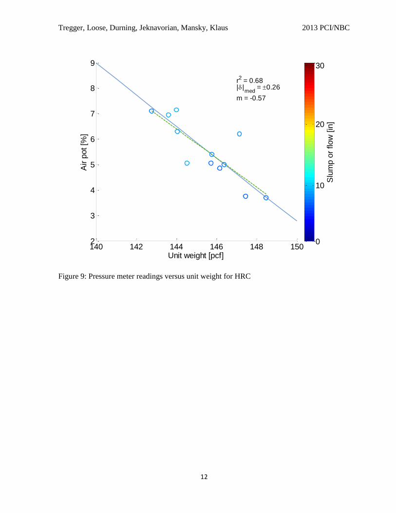
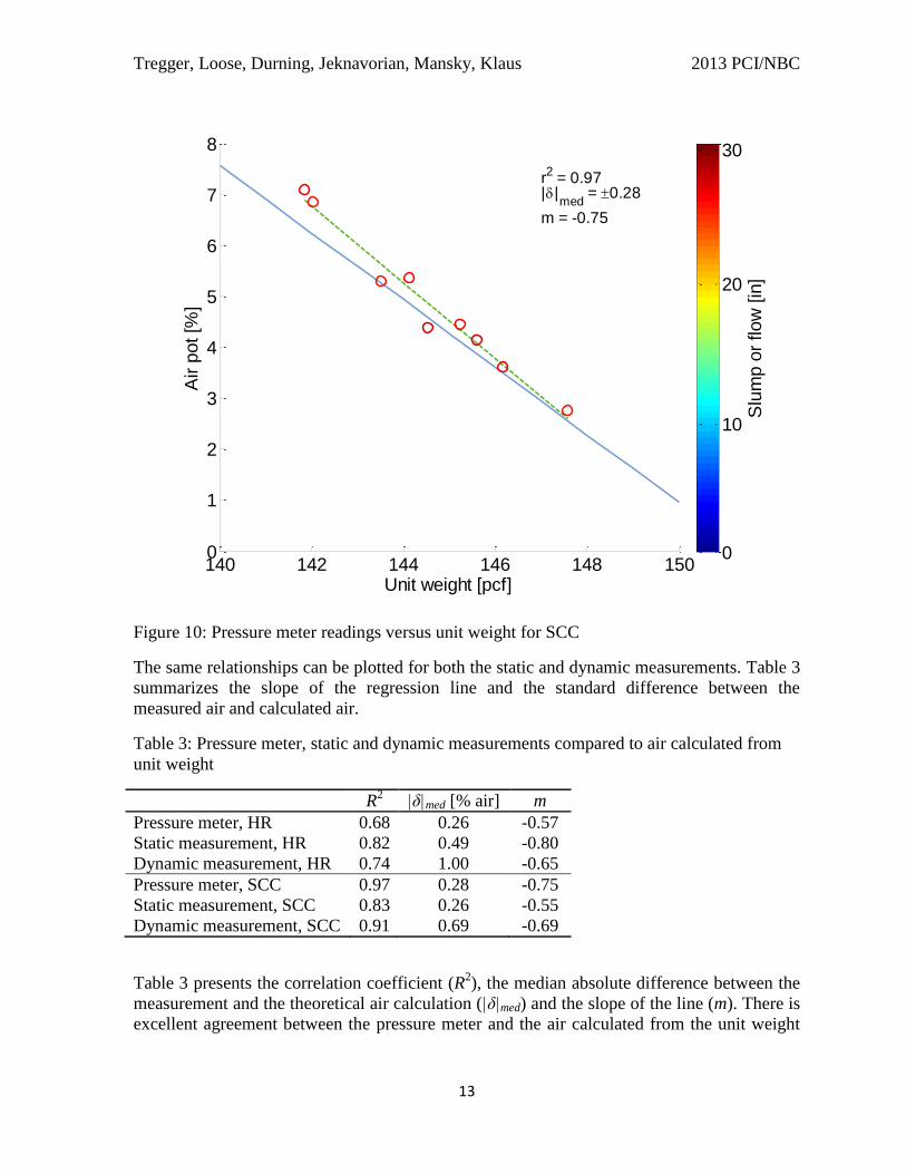
From another perspective, the pressure meter as well as air measurements from the acoustic
sensor can be compared to the unit weight and theoretical air content as determined by the
gravimetric method. Figure 9 and Figure 10 show the relationship between air content
readings and unit weight for HRC and SCC respectively. The dotted line represents the
regression line, while the solid line represents the theoretical air content as calculated by the
gravimetric method. The median absolute difference between the two is 0.26% air for the
HRC and 0.28% air for the SCC.
0 2 4 6 8 100
1
2
3
4
5
6
7
8
9
10
Cement [pcy]
625
750
Air pot [%]
Dynam
ic m
easure
ment [%
]
r2 = 0.86
||med
= 0.69
m = 1.04
Slu
mp o
r flow
[in
]
0
10
20
30
Tregger, Loose, Durning, Jeknavorian, Mansky, Klaus 2013 PCI/NBC
12
Figure 9: Pressure meter readings versus unit weight for HRC
140 142 144 146 148 1502
3
4
5
6
7
8
9
Unit weight [pcf]
Air p
ot [%
]
r2 = 0.68
||med
= 0.26
m = -0.57
Slu
mp o
r flow
[in
]
0
10
20
30
Tregger, Loose, Durning, Jeknavorian, Mansky, Klaus 2013 PCI/NBC
13
Figure 10: Pressure meter readings versus unit weight for SCC
The same relationships can be plotted for both the static and dynamic measurements. Table 3
summarizes the slope of the regression line and the standard difference between the
measured air and calculated air.
Table 3: Pressure meter, static and dynamic measurements compared to air calculated from
unit weight
R2 |δ|med [% air] m
Pressure meter, HR 0.68 0.26 -0.57
Static measurement, HR 0.82 0.49 -0.80
Dynamic measurement, HR 0.74 1.00 -0.65
Pressure meter, SCC 0.97 0.28 -0.75
Static measurement, SCC 0.83 0.26 -0.55
Dynamic measurement, SCC 0.91 0.69 -0.69
Table 3 presents the correlation coefficient (R2), the median absolute difference between the
measurement and the theoretical air calculation (|δ|med) and the slope of the line (m). There is
excellent agreement between the pressure meter and the air calculated from the unit weight
140 142 144 146 148 1500
1
2
3
4
5
6
7
8
Unit weight [pcf]
Air p
ot [%
]
r2 = 0.97
||med
= 0.28
m = -0.75
Slu
mp o
r flow
[in
]
0
10
20
30

Tregger, Loose, Durning, Jeknavorian, Mansky, Klaus 2013 PCI/NBC
14
for both the HRC and the SCC. The static measurement for the HRC has a higher median
absolute difference compared to the pressure meter, but more importantly, the slope is
different. This may suggest either that there is a fundamental difference between either how
the measurements are made, or it may be due to any changes in air content from the time the
static measurement is made and the time the unit weight is recorded. For example,
discharging and rodding take place during this time and may lower the air content. The static
measurement for the SCC has practically the same median absolute difference. This may be
explained by the fact that no rodding was performed due to the high workability. Concerning
the dynamic measurements, the median absolute difference is higher in both cases, but this is
to be expected since the dynamic measurements tend to be higher than the static
measurements.
ACTUAL PLANT DATA
The acoustic sensor has been installed in several precast plants to demonstrate full scale use.
The sensor is manufactured to the same dimensions as common moisture meters, and thus
can be installed easily in the side or bottom of the mixer, as shown in Figure 11. Figure 12
shows a typical mix cycle for an actual precast plant mixer. Note that the signature is similar
to the lab scale mixer at 310 seconds, as the mixer goes from a high mixing speed to a fully
static state resulting in a rapid change in air.
Figure 11: Installed sensor at precast plant

Tregger, Loose, Durning, Jeknavorian, Mansky, Klaus 2013 PCI/NBC
15
Figure 12: Real-time output from precast plant mixer
Data used in Figure 13 and Figure 14 represents both HRC and SCC over several months at
one particular precast plant. Figure 13 compares static measurements (truly static in this case)
to the pressure meter readings while Figure 14 compares dynamic measurements.
Figure 13: Plant data comparing static measurements to pressure meter readings
0 100 200 300 400 500 600 700 8006
8
10
12
Time [s]
Air c
onte
nt [%
]
0 2 4 6 8 10 120
2
4
6
8
10
12
Air pot [%]
Sta
tic m
easure
ment [%
]
r2 = 0.45
||med
= 0.88
m = 0.9
Slu
mp o
r flow
[in
]
0
10
20
30

Tregger, Loose, Durning, Jeknavorian, Mansky, Klaus 2013 PCI/NBC
16
Figure 14: Plant data comparing dynamic measurements to pressure meter readings
The standard errors in both cases were slightly higher, but similar to those found in the lab-
scale trials. In addition, the dynamic measurements are also higher than the corresponding
static measurements again, due to influences of stopped mixing and rodding that occurs
during the pressure meter measurements.
CONCLUSIONS
This preliminary study has demonstrated both at a lab and plant scale that the novel air
measuring system provides an accurate and robust air measurement over a wide range of air
contents. Real-time measurement also provides a first indication into how air content can
change with mixing energy and chemical admixture addition. Future work will aim to test the
technology across many different concrete systems including mix design, chemical
admixture systems, and mixing sequences.
0 2 4 6 8 10 120
2
4
6
8
10
12
Air pot [%]
Dynam
ic m
easure
ment [%
]
r2 = 0.66
||med
= 1.79
m = 1.05
Slu
mp o
r flow
[in
]
0
10
20
30

Tregger, Loose, Durning, Jeknavorian, Mansky, Klaus 2013 PCI/NBC
17
ACKNOWLEDGEMENTS
The authors gratefully acknowledge the concrete crew at W.R. Grace.
REFERENCES
1. Jeknavorian, A. A., “Air entraining Admixtures,” Significance of Tests and
Properties of Concrete and Concrete-Making Materials; STP 169D, 2006, Chapter
41.
2. ACI 318-11, Building Code Requirements for Structure Concrete. Farmington Hills.
American Concrete Institute, 2011.
3. Whiting, D.A. and Nagi, M.A., Manual on Control of Air Content in Concrete,
Portland Cement Association, 1998.
4. ASTM C260, Annual Book of ASTM Standards, Vol. 04.02.
5. Wilson, M., “Measurement of Air Content,” Concrete Bridge Views, No. 61,
May/June 2010.
6. Gysling, D. L., Loose, D. H., “Sonar-based volumetric flow and entrained air
measurement for pulp and paper applications,” TAPPI Spring Technical Conference,
Paper 58-1, Chicago, IL, May 2003.
7. McWilliam, D., Duggins, R. K., “Speed of sound in bubbly liquids,” Proc Instn Mech
Engrs, Vol 184, Part 3C, 1969-1970.
8. Stoor, T., Ämmälä, A. Niinimäki, J., “Measurement of air content of pulp suspension
– sonar method,” APPITA 2005 pulp and paper conference, Auckland May 2005.
9. Gysling, D. L., Banach, T., “Accurate liquid phase density measurement of aerated
liquids using speed of sound augmented Coriolis meters,” ISA, Houston, October
2004.
10. Wood, A. B., A Textbook of Sound, New York, NY, 1st edition, 1930.
11. Wilson, P. S., Reed, A. H., Wood, W. T., Roy, R. A., “The low-frequency sound
speed of fluid-like gas-bearing sediments,” J. Acoustical Society of America, April
2008.