introducing originality and innovation in engineering...
TRANSCRIPT

Introducing originality and innovation in engineering teaching: thehydraulic design of culverts
H. CHANS ON †
Recently, the teaching of engineering design has become a presentation of stan-dards and codes rather than the learning of sound design practices. Too manystudents request formulae and equations to solve a design exercise and they failto develop any design originality. The present student attitude leads to younggraduate engineers without critical ability and innovative �air. The writer hasdeveloped an innovative hydraulic design exercise based upon culvert design.Each design exercise could lead to more than one correct design per student inthe class. Students have to learn basic design calculations based upon lecturematerial, notes, �eld visits and laboratory experiment. The practical component(laboratory, �eld visit) contributes signi�cantly to their understanding of the com-plete system, including some basic safety and professional issues.
1. IntroductionThe paper presents a new way to teach hydraulic design to civil and environ-
mental engineering students in an undergraduate curriculum. The hydraulic designof a culvert is introduced as part of a complete design approach. The paper describesengineering design techniques in which individual originality and innovation isrequired. The analysis of the design procedures highlights the original input thateach student must bring. Case studies are used to support the undergraduateteaching of open channel hydraulics and design of hydraulic structures. The standardtext recommended in the course is The hydraulics of Open Channel Flow: An Intro-duction (Chanson 1999).
According to the dictionaries, an engineer is ‘a designer or builder, a person whocarries through an enterprise by skilful or artful contrivance’ (e.g. The PenguinEnglish Dictionary 1985–86, Merriam-Webster’s Collegiate Dictionary 1997). Inrecent times, the teaching of engineering design has become more the presentationof standards and codes than the learning of design originality and safety. At under-graduate level and in postgraduate classes, too many students request formulae andequations to solve a design exercise. They fail often to read the speci�cations, toassess the problem and to analyse the tasks involved, and to develop an originaldesign. The present student attitude leads to young graduate engineers withoutcritical ability and innovative �air.
In practice, many engineers duplicate existing designs, including their mistakes.A famous example in hydraulic design is the spillway structure of the New Victoriadam, Perth (1990, Australia). The design of the spillway was copied from the Upper
EUR. J. ENG. ED., 2000, VOL. 25, NO. 4, 377–391
† Department of Civil Engineering, The University of Queensland, Brisbane QLD 4072,Australia. e-mail: [email protected]
European Journal of Engineering Education ISSN 0343-3797 print/ISSN 1469-5898 online© 2000 Taylor & Francis Ltd
http://www.tandf.co.uk/journals
Stillwater dam (1987, USA). The US design was to be a 4.6-m long broad crestfollowed by a straight 59º stepped chute, but the �nal design is a 9.1-m long broadcrest followed by a 72º chute and then a 59º chute. The change in design was madeto allow truck access. It had no hydrodynamic or structural validity. In fact, the �naldesign has increased the risks of jet de�ection and improper operation during over-�ows at the transition between the crest and the 72º chute. None the less, the UpperStillwater crest design was duplicated for the New Victoria dam spillway withoutcritical analysis (Chanson 1997).
The author has developed an innovative hydraulic design exercise which couldlead to more than one correct design per student in the class. Students must developtheir individual expertise in culvert design. They have to learn how to calculate anef�cient design based upon lecture material, notes, �eld visit(s) and laboratoryexperiment. They are expected to provide detailed drawings and justi�cations oftheir calculations.
1.1 Culvert designA culvert is a covered channel of relatively short length designed to pass water
through an embankment (e.g. highway, railroad, dam). The design requires a hydro-logical study of the upstream catchment to estimate the maximum (design)discharge and the risks of exceptional (emergency) �oods. The dimensions of theculvert are based on hydraulic, structural and geotechnical considerations. Indeed,the culvert height and width affect the size and cost of the embankment. The culvertimpact on the environment must also be taken into account, e.g. �ooding of theupstream plain.
The design process is a system approach. The system must be identi�ed as wellas the design objectives and constraints. A detailed analysis of it must be conductedand the engineers should ask if their �nal design responds to the objectives.
2. Hydraulic design of culvertThe hydraulic performances of a culvert are the design discharge Qdes, the
upstream total head and the maximum (acceptable) head loss D H. Head losses mustbe minimized to reduce upstream backwater effects (i.e. upstream �ooding). Theprimary design constraints are: (1) the cost must be (always) minimum; (2) theaf�ux1 must be small and preferably minimum; (3) eventually the embankmentheight may be given or may be part of the design; and (4) a scour protection may beconsidered, particularly if a hydraulic jump might take place near the culvert outlet.The hydraulic design is basically an optimum compromise between dischargecapacity and head loss. In practice, short culverts are designed for free-surface �owwith critical �ow conditions2 in the throat. The �nal design may vary from a simplegeometry (i.e. standard box culvert) to a hydraulically-smooth shape (i.e. minimumenergy loss (MEL) culvert3) (�gures 1 and 2).
3. Standard culvertsA standard culvert is designed to pass water at minimum cost. The culvert
construction must be simple, e.g. circular pipes, precast concrete boxes. The culvert�ow may exhibit various �ow patterns, e.g. free-surface inlet �ow conditions orsubmerged entrance, inlet control or outlet control (�gures 1 and 3).4
The discharge capacity of the barrel is primarily related to the �ow pattern.
378 H. Chanson
Originality and innovation in teaching 379
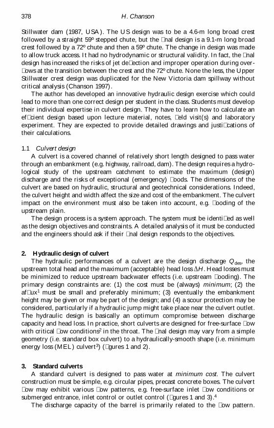
Figure 1. Sketch of a standard culvert operation: inlet control and outlet control.
When free-surface �ow takes place in the barrel, the discharge is �xed only by theentry conditions, and the discharge is typically estimated as:
Q 2 2—– = CD * —– * Ö 1 —– *g 2 *(H1 – zinlet)1.5 Free-surface inlet �ow (1)B 3 3
Q—– = C*D* Ö [2*g*(H1 – zinlet – C*D)]B
Submerged entrance and free-surface barrel �ow (2)
where B is the barrel width and D is the barrel height (�gure 1) (Henderson 1966).CD equals 1 for rounded vertical inlet edges and 0.9 for square-edged inlets. C equals0.6 for square-edged sof�t and 0.8 for rounded sof�t. For drowned culverts (i.e.outlet control), the discharge is determined by the culvert resistance (i.e. primaryand secondary losses) (e.g. US Bureau of Reclamation 1987, Concrete Pipe Associ-ation of Australasia 1991).
3.1. Design procedureFor standard culverts the design process is divided into two parts (e.g. Herr and
Bossy 1965, HEC No. 5). First, a system analysis must be carried out to determinethe objectives of the culvert, the design data, the constraints including the design�ow Qdes and the design upstream total head Hdes.
380 H. Chanson
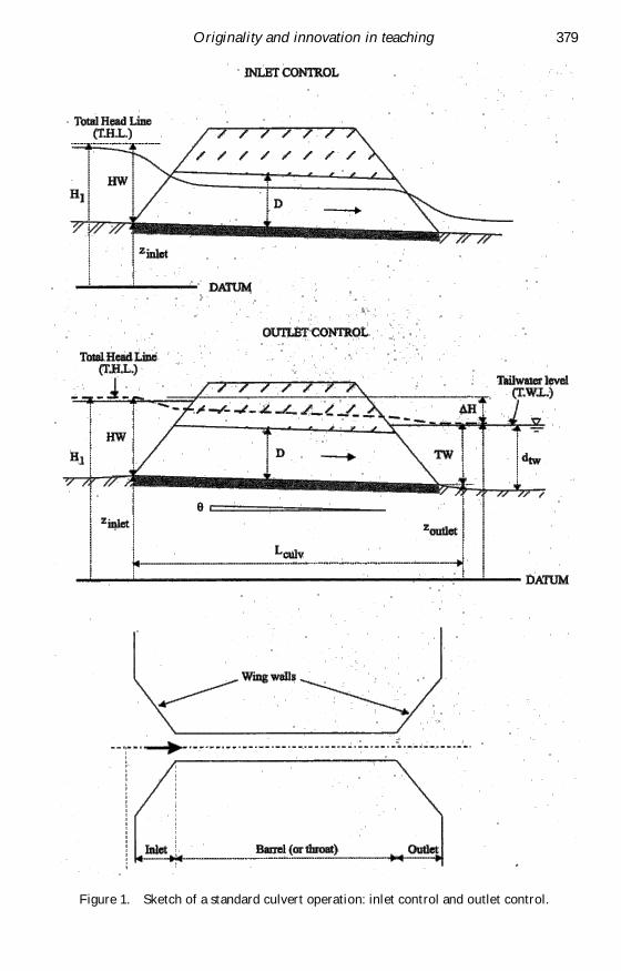
Figure 2. Sketch of a minimum energy loss culvert.
Originality and innovation in teaching 381
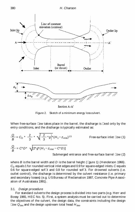
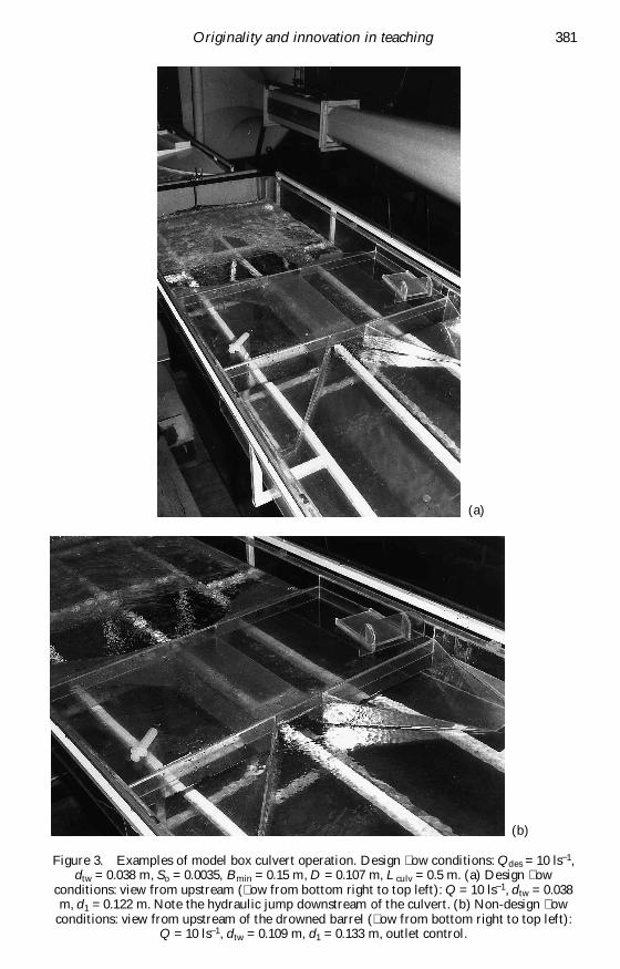
Figure 3. Examples of model box culvert operation. Design �ow conditions: Qdes = 10 ls–1,dtw = 0.038 m, So = 0.0035, Bmin = 0.15 m, D = 0.107 m, Lculv = 0.5 m. (a) Design �ow
conditions: view from upstream (�ow from bottom right to top left): Q = 10 ls–1, dtw = 0.038m, d1 = 0.122 m. Note the hydraulic jump downstream of the culvert. (b) Non-design �ow
conditions: view from upstream of the drowned barrel (�ow from bottom right to top left):Q = 10 ls–1, dtw = 0.109 m, d1 = 0.133 m, outlet control.
(a)
(b)
In a second stage, the barrel size is selected by a test-and-trial procedure, inwhich both inlet control and outlet control calculations are performed. At the end,the optimum size is the smallest barrel size allowing for inlet control operation.Calculations of the barrel size are iterative:
(1) Choose the barrel dimensions.(2) Assume an inlet control. Calculate the upstream total head corresponding
to the design discharge Qdes assuming inlet control for different barrel sizesuntil the upstream head H1
(ic) satis�es the design speci�cations (i.e. H1(ic) =
Hdes).(3) Assume an outlet control. Use design charts to calculate the head loss D H
from inlet to outlet for the design discharge Qdes (e.g. US Bureau of Recla-mation 1987). Calculate the upstream total head H1
(oc): H1(oc) = Htw + D H,
where Htw is the tailwater head at design �ow.(4) Compare the inlet control and outlet control results: Hdes = H1
(ic) _ H1(oc).
The larger value controls.
When the inlet control design head Hdes (used in step 2) is larger than H1(oc), inlet
control operation is con�rmed and the barrel size is correct. If H1(oc) is larger than
Hdes, outlet control takes place. Step 3 must be then repeated with an increasedbarrel size until H1
(oc) satis�es the design speci�cation Hdes.
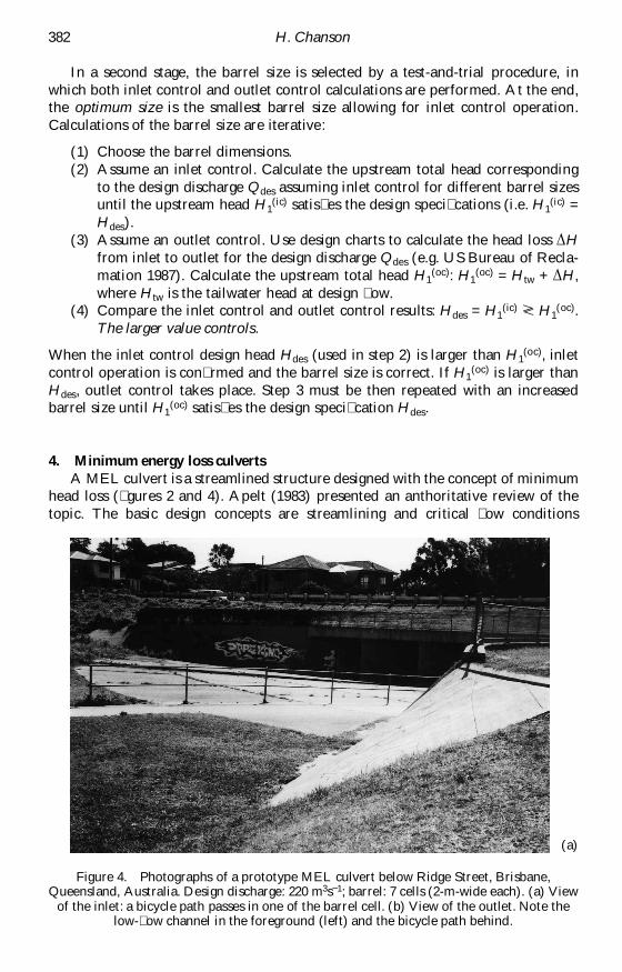
4. Minimum energy loss culvertsA MEL culvert is a streamlined structure designed with the concept of minimum
head loss (�gures 2 and 4). Apelt (1983) presented an anthoritative review of thetopic. The basic design concepts are streamlining and critical �ow conditions
382 H. Chanson
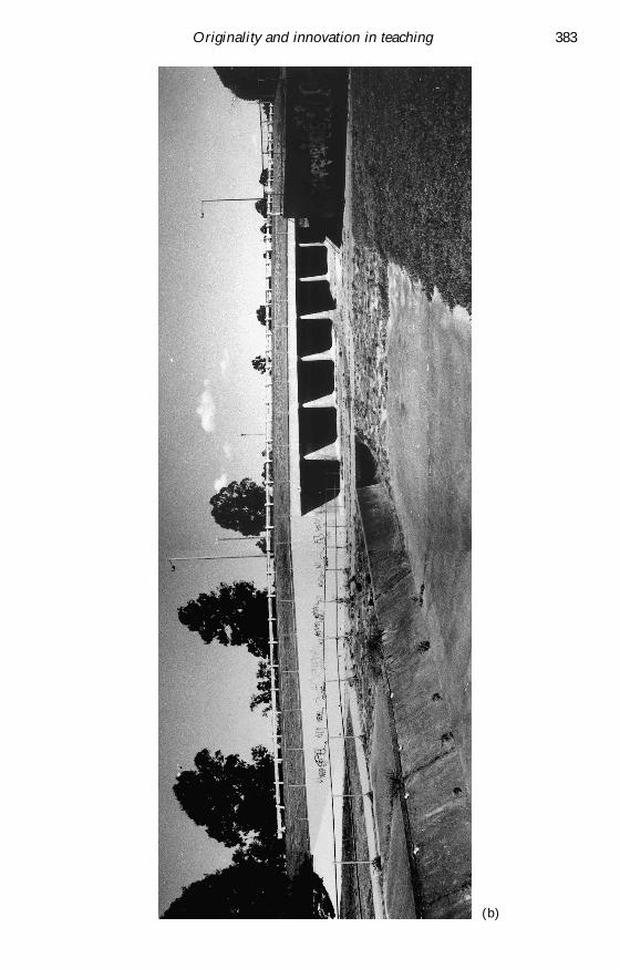
Figure 4. Photographs of a prototype MEL culvert below Ridge Street, Brisbane,Queensland, Australia. Design discharge: 220 m3s–1; barrel: 7 cells (2-m-wide each). (a) View
of the inlet: a bicycle path passes in one of the barrel cell. (b) View of the outlet. Note thelow-�ow channel in the foreground (left) and the bicycle path behind.
(a)
Originality and innovation in teaching 383
(b)

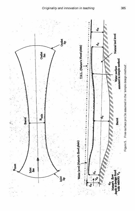
through all the waterway (inlet, barrel, outlet) (�gure 5). The intake is designed witha smooth contraction into the barrel while the outlet (or diffuser) is shaped as asmooth expansion back to the natural channel. In a satisfactory design, the �owstreamlines follow very smooth curves and no separation is observed as for a Ventur-meter installed in a circular pipe. MEL structure are designed to achieve critical �owconditions in all the engineered waterway because the maximum discharge per unitwidth for a given speci�c energy is achieved at critical �ow conditions (e.g. Hender-son 1966). At the throat the discharge per unit width may be increased by loweringthe barrel invert below the natural ground level.
4.1. A simple design methodProfessor C. J. Apelt (The University of Queensland) proposed a simple method
to calculate the basic characteristics of a MEL culvert. This method gives a prelimi-nary design.5 Full calculations using the backwater equations are required to predictaccurately the free-surface pro�le.
1. Decide the design discharge Qdes and the associated total head line (THL)in the �ood plain.
(A) Neglect energy losses2.1. Calculate the waterway characteristics in the throat (i.e. barrel) for critical
�ow conditions.2.2. Calculate the inlet width Bmax assuming critical �ow conditions and natural
bed level (i.e. D zo = 0).3.1. Decide the shapes of the fans.3.2. Calculate the geometry of the fans to satisfy critical �ow conditions every-
where (e.g. �gure 7).In the above steps, either the barrel width Bmin is selected and the barrelinvert drop D zo is calculated; or D zo is chosen and the barrel width is calcu-lated.
(B) Include the energy losses4. Adjust the bed pro�le of the waterway to take into account the energy
losses.5. Check the ‘off-design’ performances, i.e. Q > Qdes and Q < Qdes.
5. Teaching culvert designThe author developed a pedagogic tool to introduce students to culvert design.
It covers lecture material, home work associated with site visit(s) as well as a culvertlaboratory study which includes an audiovisual presentation, physical models ofculverts and numerical computations (using the program HydroCulv). The aim ofthe course is to introduce students to some original hydraulic design as well as tohydraulic computations of culvert design using a commercial package.
Following the lecture material, students are involved in home work associatedwith site visit(s) (individually or in groups). For a particular case study, the studentsare asked either to design a standard box culvert for a speci�ed �ow rate or to calcu-late the design discharge capacity of an existing structure, and the associatedupstream water levels. Then they are requested to design a MEL waterway to passa speci�c �ood (e.g. 1 in 50 years �ood) and to compare their design with the corre-sponding standard box culvert. For each site, there is usually a single optimumstandard culvert design and a multitude of correct MEL design. The multiplicity of
384 H. Chanson
Originality and innovation in teaching 385
Fig
ure
5.F
ree-
surf
ace
pro�
le a
ssum
ed in
the
‘sim
ple
desi
gn m
etho
d’.
MEL culvert designs results from the wide range of inlet and outlet shapes, e.g. para-bolic, elliptic or hyperbolic sidewall curves.
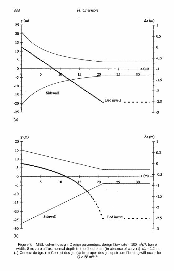
Considering a practical application, the culvert design parameters are: designdischarge = 100 m3s–1, barrel width = 8 m, zero af�ux.6 The students are asked todesign a box culvert with zero af�ux, a box culvert with an 8-m-wide barrel and aMEL culvert with zero af�ux and an 8-m-wide throat. A standard box culvert withinvert set at ground level would need to be 50-m-wide to pass the �ood withoutaf�ux, while an 8-m-wide box culvert would cause an upstream water level rise(af�ux) of about 4.4 m (�gure 6). The MEL culvert design would require a 2.6-mdeep excavation of the barrel. Figure 7 (a, b) shows proper inlet designs that wouldpass the design �ow rate with zero af�ux. Each �gure shows the sidewalls and centre-line invert elevation only. Figure 7(c) presents an improper design that would createsome upstream �ooding for �ow rates larger than 60% of the design �ow rate.7
Note the signi�cant differences between the standard and MEL culvert designs.The MEL waterway concept was developed by Profs G. R. McKay and C. J. Apeltfor the coastal plains of Queensland (North-East of Australia). Torrential rainsduring the wet season, associated with very small natural plain �ood slope (So ~ 0.001)and little fall (or head loss), place a heavy demand on culverts.
During each case study, the students may choose a multitude of inlet shapes. Acorrect design must be streamlined with occurrence of critical �ow conditions at anylocation between the inlet lip and barrel. The complete inlet design requires thedrawings of the lines of constant invert elevation. These are equipotential lines andthe complete inlet design is similar to a �ow net analysis (e.g. Vallentine 1969).
6. Laboratory workEach student spends one afternoon in a hydraulic laboratory (see the appendix).
The students are �rst introduced to culvert design (video presentation, Apelt 1994)before performing measurements in a standard box culvert model (�gure 3) and adownstream MEL culvert model (�gure 4). The models discharge an identical �owrate. They are made of �breglass and perspex, and the students can see the �owpatterns in the channel, barrel, inlet and outlet for design and non-design �owconditions8 (�gure 3). Identical �ow conditions are input to a commercial softwarefor standard culvert design (e.g. HydroCulv). Comparisons between the physicalmodel and computer program results are conducted and discussed with the help ofthe physical model. The comparative performances of standard and MEL culvertsare also discussed for design and non-design �ow conditions. At the end of the after-noon, the students are challenged on the effect of a �ood larger than the design �ow.Their response is discussed in a group before being tested in the physical models for1.5*Qdes.
7. Discussion: a teacher’s opinionThe author has taught hydraulic design at undergraduate and postgraduate levels
for more than 10 years. At undergraduate levels, he introduces the students tospillway and culvert design. It is the author’s opinion that the hydraulic design of aculvert offers a unique opportunity. The design exercise is based upon very basichydraulic material, i.e. the concept of speci�c energy, critical �ow conditions, ideal-�uid �ow. Each case study may be developed as a series of design exercises withincreasing complexity, e.g. starting with a standard culvert design and ending with a
386 H. Chanson

Originality and innovation in teaching 387
Fig
ure
6.F
ree-
surf
ace
com
puta
tion
s fo
r a
stan
dard
box
cul
vert
(pr
ogra
m H
ydro
Cul
v). D
esig
n pa
ram
eter
s: d
esig
n �o
w r
ate
= 1
00 m
3 s– 1
; bar
rel
wid
th: 8
m; n
orm
al d
epth
in t
he �
ood
plai
n (i
n ab
senc
e of
cul
vert
): 1
.2 m
.
388 H. Chanson
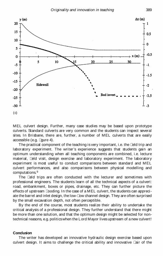
Figure 7. MEL culvert design. Design parameters: design �ow rate = 100 m3s–1; barrelwidth: 8 m; zero af�ux; normal depth in the �ood plain (in absence of culvert): do = 1.2 m.
(a) Correct design. (b) Correct design. (c) Improper design: upstream �ooding will occur forQ > 58 m3s–1.
(a)
(b)
MEL culvert design. Further, many case studies may be based upon prototypeculverts. Standard culverts are very common and the students can inspect severalsites. In Brisbane, there are, further, a number of MEL culverts that are easilyaccessible (e.g. �gure 4).
The practical component of the teaching is very important, i.e. the �eld trip andlaboratory experiment. The writer’s experience suggests that students gain anoptimum understanding when all teaching components are combined, i.e. lecturematerial, �eld visit, design exercise and laboratory experiment. The laboratoryexperiment is most useful to conduct comparisons between standard and MELculvert performances, and also comparisons between physical modelling andcomputations.9
The �eld trips are often conducted with the lecturer and sometimes withprofessional engineers. The students learn of all the technical aspects of a culvert:road, embankment, boxes or pipes, drainage, etc. They can further picture theeffects of upstream �ooding. In the case of a MEL culvert, the students can appreci-ate the barrel and inlet design, the low-�ow channel design. They are often surprisedby the small excavation depth, not often perceptible.
By the end of the course, most students realize their ability to undertake thecritical analysis of a professional design. They further understand that there mightbe more than one solution, and that the optimum design might be selected for non-technical reasons, e.g. politics when the Lord Mayor lives upstream of a new culvert!
ConclusionThe writer has developed an innovative hydraulic design exercise based upon
culvert design. It aims to challenge the critical ability and innovative �air of the
Originality and innovation in teaching 389
(c)

students, as indeed each design exercise may lead to more than one correct designper student in the class. Students have to learn basic design calculations based uponlecture material, notes, �eld visits and laboratory experiment. The practicalcomponent (laboratory, �eld visit) contributes signi�cantly to their understandingof the complete system, including some basic safety and professional issues.
It is the author’s opinion that the described teaching method has been verysuccessful in the context of Australian civil and environmental engineering students.He further believes that the �eld visit under the supervision of the lecturer andsometimes of professional engineers gives an added dimension to the hydraullicdesign teaching.
AcknowledgementsThe author thanks especially Prof. Colin J. Apelt, University of Queensland, for
his help and assistance. The technical background of the paper derived from Prof.Apelt’s personal lecture notes.
Appendix: Laboratory componentsAudio-visual material:
Apelt, C. J., 1994, The minimum energy loss culvert, Video-cassette VHS colour, Depart-ment of Civil Engineering, University of Queensland, Australia, 18 min.
Physical model (standard culvert):The physical model characteristics are: Qdes = 10 ls–1, Bmax = 1 m, Bmin = 0.15 m, D =0.11 m, Lculv = 0.5 m, dtw = 0.038 m, intake and outlet: 45º diffuser, So = 0.0035.
Physical model (MEL culvert):The physical model characteristics are: Qdes = 10 ls–1, Bmax = 1 m, Bmin = 0.10 m, D =0.17 m, barrel length: 0.6 m, dtw = 0.038 m, barrel elevation 0.124 m lower than river bed.
Computer program:HydroCulv Version 1.1 (HydroTools Software: [email protected]).
Notes1. The af�ux is the rise of water level above normal free-surface level upstream of the culvert.
It is a measure of the upstream �ooding caused by the culvert design.2. In open channel �ows, the �ow conditions, such as the speci�c energy is minimum, are
called the critical �ow conditions (e.g. Henderson 1966, Chanson 1999).3. The design of a MEL culvert is associated with the concept of constant total head. The inlet
and outlet must be steamlined in such a way that signi�cant form losses are avoided. Foran introduction on MEL culverts, see Apelt (1994). For a complete review of MELwaterways, see Apelt (1983).
4. Inlet control occurs when the �ow is controlled by the upstream �ow conditions and the�ow rate is independent of the downstream water level.
5. The simple method is based on the assumption that the �ow is critical from the inlet tooutlet lips including in the barrel.
6. Other design parameters are: normal depth in the �ood plain = 1.2 m (in absence ofculvert), bed slope = 0.005, culvert length = 24 m. Barrel height = 3 m.
7. The extent of the upstream �ooding could be determined with detailed backwatercomputations and physical modelling.
8. The experiments are conducted with �ow rates ranging from 0.05 to 1.5 times the designdischarge.
9. Most professional softwares perform one-dimensional or two-dimensional calculations.They fail to address the three-dimensional nature of the �ow that may be visualized in thephysical model.
390 H. Chanson

ReferencesAPELT, C. J., 1983, Hydraulics of minimum energy culverts and bridge waterways. Australian
Civil Engineering Transactions, CE25, 89–95.APELT, C. J., 1994, The minimum energy loss culvert, Videocassette VHS colour, Department
of Civil Engineering, University of Queensland, Australia, 18 min.CHANSON, H., 1997, A short history of stepped cascades in Australia. ANCOLD Bulletin, 106,
101–111.CHANSON, H., 1999, The Hydraulics of Open Channel Flows: An Introduction (London:
Edward Arnold).CONCRETE PIPE ASSOCIATION OF AUSTRALIA, 1991, Hydraulics of Precast Concrete Conduits
(Jenkin Buxton Printers, Australia).HENDERSON, F. M., 1966, Open Channel Flow (New York: MacMillan).HERR, L. A. AND BOSSY, H. G., 1965, Hydraulic Charts for the Selection of Highway Culverts.
Hydraulic Eng. Circular, US Dept. of Transportation, Federal Highway Admin., HECNo. 5, December.
US DEPARTMENT OF THE INTERIOR, 1987, Design of Small Dams. Denver CO: Bureau ofReclamation.
VALLENTINE, H. R., 1969, Applied Hydrodynamics (London: Butterworths).
About the authorHubert Chanson received a degree of ‘Ingénieur Hydraulicien’ from the Ecole NationaleSupérieure d’Hydraulique et de Mécanique de Grenoble (France) in 1983 and a degree of‘Ingénieur Génie Atomique’ from the ‘Institut National des Sciences et TechniquesNucléaires’ in 1984. He worked for industry in France as a R&D engineer at the AtomicEnergy Commission from 1984 to 1986, and as a computer professional in �uid mechanics forThomson-CSF between 1989 and 1990. From 1986 to 1988, he studied at the University ofCanterbury (New Zealand) as part of a PhD project. In 1999, he was awarded a Doctor ofEngineering at the University of Queensland. He has been a senior lecturer in �uid mechan-ics, hydraulics and environmental engineering at the University of Queensland since 1990.His research interests include design of hydraulic and coastal structures, experimental investi-gations of two-phase �ows, water modelling in coastal and hydraulic structures, environ-mental management and natural resources, and engineering heritage. He has authored threebooks: Hydraulic Design of Stepped Cascades, Channels, Weirs and Spillways, Air BubbleEntrainment in Free-surface Turbulent Shear Flows and The Hydraulics of Open ChannelFlows: An Introduction. His publication record includes over 160 international refereedpapers. Dr Chanson has been active also as consultant for both governmental agencies andprivate organizations. He has been awarded four fellowships from the Australian Academyof Science. In 1995 he was a Visiting Associate Professor at National Cheng Kung University(Taiwan ROC) and he was a Visiting Research Fellow at Toyohashi University of Technology(Japan) in 1999. Dr Chanson was the keynote lecturer at the 1998 ASME Fluids EngineeringSymposium on Flow Aeration and at the Workshop on Flow Characteristics aroundHydraulic Structures (Nihon University, Japan 1998). He gave an invited lecture at the Inter-national Workshop on Hydraulics of Stepped Spillways (ETH-Zürich, 2000). He lecturedseveral short courses in Australia and overseas (e.g. Japan, Taiwan).
Originality and innovation in teaching 391