introducing the centre for railway engineering
TRANSCRIPT
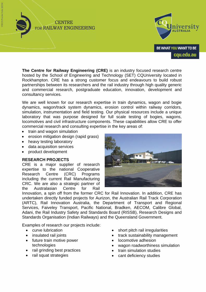
The Centre for Railway Engineering (CRE) is an industry focused research centre hosted by the School of Engineering and Technology (SET) CQUniversity located in Rockhampton. CRE has a strong customer focus and endeavours to build robust partnerships between its researchers and the rail industry through high quality generic and commercial research, postgraduate education, innovation, development and consultancy services.
We are well known for our research expertise in train dynamics, wagon and bogie dynamics, wagon/track system dynamics, erosion control within railway corridors, simulation, instrumentation and field testing. Our physical resources include a unique laboratory that was purpose designed for full scale testing of bogies, wagons, locomotives and civil infrastructure components. These capabilities allow CRE to offer commercial research and consulting expertise in the key areas of: train and wagon simulation erosion mitigation design (rapid grass) heavy testing laboratory data acquisition services product development
RESEARCH PROJECTS CRE is a major supplier of research expertise to the national Cooperative Research Centre (CRC) Programs including the current Rail Manufacturing CRC. We are also a strategic partner of the Australasian Centre for Rail Innovation, a spin off from the former CRC for Rail Innovation. In addition, CRE has undertaken directly funded projects for Aurizon, the Australian Rail Track Corporation (ARTC), Rail Innovation Australia, the Department of Transport and Regional Services, Faiveley Transport, Pacific National, Bradken, AECOM, Calibre Global, Adani, the Rail Industry Safety and Standards Board (RISSB), Research Designs and Standards Organisation (Indian Railways) and the Queensland Government.
Examples of research our projects include: curve lubrication insulated rail joints future train motive power
technologies rail grinding best practices rail squat strategies
short pitch rail irregularities track sustainability management locomotive adhesion wagon roadworthiness simulation train simulation studies cant deficiency studies

POSTGRADUATE RESEARCH STUDENTS CRE is proud to host and provide research higher degree training for postgraduate students. CRE, due to its industry environment, provides a multidisciplinary context for students and excellent opportunities to network with industry partners and rail researchers.
STAFFING The members and associates of CRE comprise experienced academics, researchers, technicians and software development staff with expertise in railway engineering, rollingstock engineering, railway maintenance, train/wagon and traction dynamics, simulation, instrumentation, intelligent devices and software. Working at CRE offers an ideal opportunity to develop your research career in an environment of wide collaboration with other researchers and the rail industry. INNOVATION AND DEVELOPMENT Our commitment to applied research and customer focus results in involvement in projects from initial concepts right through to the development and pre-commercialisation stages. Examples of projects of this type include: erosion control intelligent train monitor OzECP brakes train health advisory system
CONTACT DETAILS CQUniversity
Bruce Highway Rockhampton QLD 4700
Enquiries: Ms Vicky Kreiser Phone: +61 (0)7 4923 2277
Email: [email protected]
Website: www.cqu.edu.au/cre
Longitudinal Train Dynamics Simulation
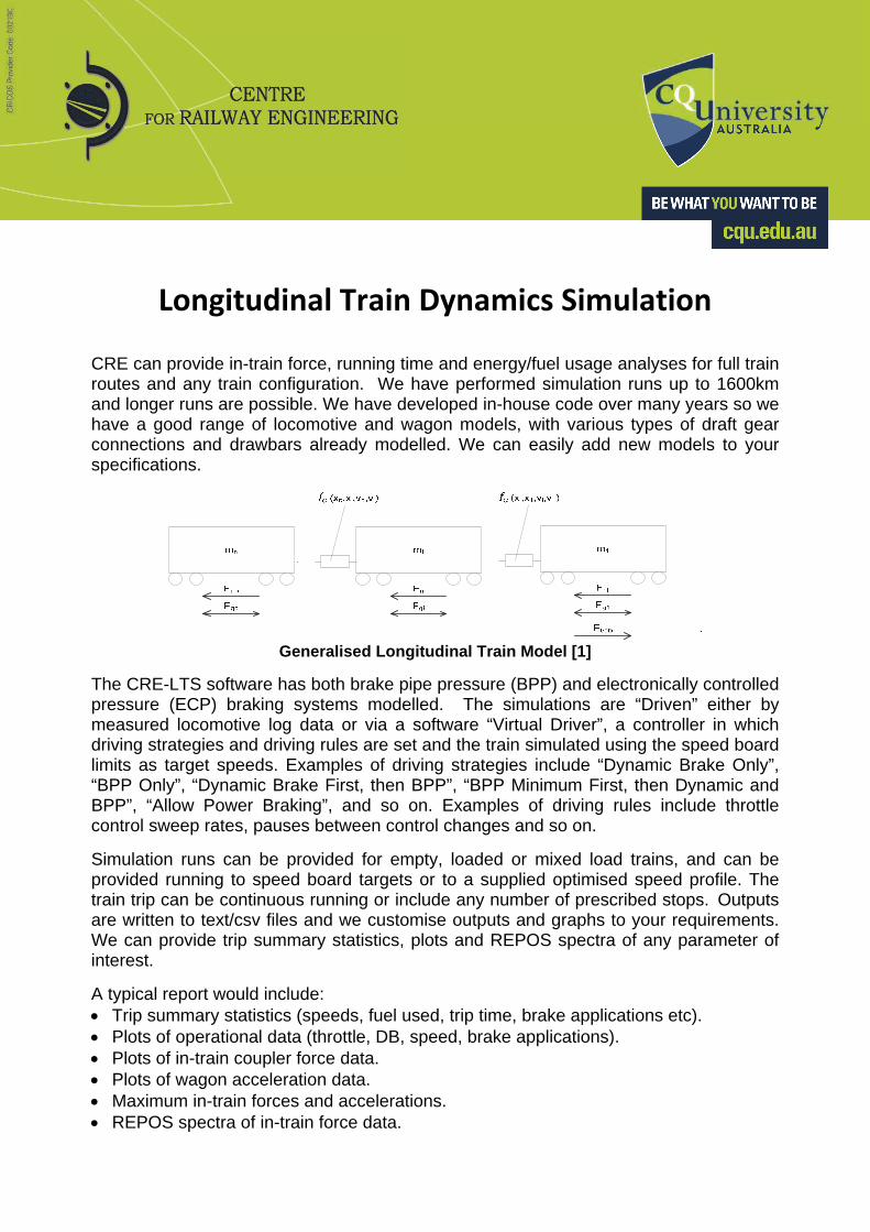
CRE can provide in-train force, running time and energy/fuel usage analyses for full train routes and any train configuration. We have performed simulation runs up to 1600km and longer runs are possible. We have developed in-house code over many years so we have a good range of locomotive and wagon models, with various types of draft gear connections and drawbars already modelled. We can easily add new models to your specifications.
Generalised Longitudinal Train Model [1]
The CRE-LTS software has both brake pipe pressure (BPP) and electronically controlled pressure (ECP) braking systems modelled. The simulations are “Driven” either by measured locomotive log data or via a software “Virtual Driver”, a controller in which driving strategies and driving rules are set and the train simulated using the speed board limits as target speeds. Examples of driving strategies include “Dynamic Brake Only”, “BPP Only”, “Dynamic Brake First, then BPP”, “BPP Minimum First, then Dynamic and BPP”, “Allow Power Braking”, and so on. Examples of driving rules include throttle control sweep rates, pauses between control changes and so on.
Simulation runs can be provided for empty, loaded or mixed load trains, and can be provided running to speed board targets or to a supplied optimised speed profile. The train trip can be continuous running or include any number of prescribed stops. Outputs are written to text/csv files and we customise outputs and graphs to your requirements. We can provide trip summary statistics, plots and REPOS spectra of any parameter of interest.
A typical report would include: Trip summary statistics (speeds, fuel used, trip time, brake applications etc). Plots of operational data (throttle, DB, speed, brake applications). Plots of in-train coupler force data. Plots of wagon acceleration data. Maximum in-train forces and accelerations. REPOS spectra of in-train force data.
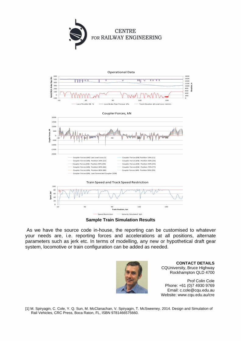
Sample Train Simulation Results
As we have the source code in-house, the reporting can be customised to whatever your needs are, i.e. reporting forces and accelerations at all positions, alternate parameters such as jerk etc. In terms of modelling, any new or hypothetical draft gear system, locomotive or train configuration can be added as needed.
[1] M. Spiryagin, C. Cole, Y. Q. Sun, M. McClanachan, V. Spiryagin, T. McSweeney. 2014. Design and Simulation of Rail Vehicles, CRC Press, Boca Raton, FL, ISBN 9781466575660.
0
200
400
600
800
1000
1200
1400
1600
1800
‐100
0
100
200
300
400
500
600
‐10 40 90 140 190
Elevation, m
Notch/D
B,%; B
rake
Pipe, kPa
Operational Data
Loco Throttle‐DB % Loco Brake Pipe Pressue kPa Track Elevation @ Lead Loco metres
0
20
40
60
80
100
‐10 40 90 140 190
Spee
d , kph
Track Position, km
Train Speed and Track Speed Restriction
Speed Restriction Velocity Simulated kph
‐2000
‐1500
‐1000
‐500
0
500
1000
1500
2000
‐10 40 90 140 190
Coup
ler Forces, kN
Coupler Forces, kN
Coupler Forces (kN) Last Lead Loco (1) Coupler Forces (kN) Position 10% (11)
Coupler Forces (kN) Position 20% (22) Coupler Forces (kN) Position 30% (33)
Coupler Forces (kN) Position 40% (44) Coupler Forces (kN) Position 50% (55)
Coupler Forces (kN) Position 60% (66) Coupler Forces (kN) Position 70% (77)
Coupler Forces (kN) Position 80% (88) Coupler Forces (kN) Position 90% (99)
Coupler Forces (kN) Last Connected Coupler (108)
CONTACT DETAILS CQUniversity,Bruce Highway
Rockhampton QLD 4700
Prof Colin Cole Phone: +61 (0)7 4930 9769
Email: [email protected] Website: www.cqu.edu.au/cre

Train – Wagon Interaction Simulation
In addition to train simulation, CRE has developed two further areas of analysis of wagon stability that are concerned with in-train forces: Lateral components of forces acting on wagons in curves Wagon pitch and jack-knifing
Larger lateral components of in-train forces occur on sharper curves due to coupler angles and also on some alignments because steeper grades are in the same areas as sharp curves. Risks for wagon stability that need to be analysed and managed include: In-train forces at start up and braking of empty trains on curves (wagon overturning) Longitudinal wagon accelerations at start up and braking of empty trains (body and bogie
pitch) Operation of empty wagons in a loaded train increases the risk of:
o lateral instability on curves – overturning and wheel climb o wagon lift off and jack-knifing
Analysis of lateral forces has been incorporated into the CRE-LTS software package and coupler angles and lateral forces are calculated from coupler force data for whole train trip simulations.
Vehicle Configuration and Coupler Angles During Curving
Coupler Angles
Lateral Forces Due to Couplers
Total Quasi-Static Lateral Forces
Total Quasi-Static Vertical Forces
Sample Coupler Angle and Force Results – Effect of Coupler Angles
2620 2630 2640 2650 2660 2670 2680 2690 2700
0
0.02
0.04
0.06
Time, (s)
Cou
ple
r an
gles
, (r
ad)
0 200 400 600 800 1000 1200 1400 1600 1800 2000-0.05
0
0.05
Time (s)
Co
up
ler
ang
le (
rad)
0 200 400 600 800 1000 1200 1400 1600 1800 2000-100
-50
0
50
100
Time (s)
La
tera
l fo
rce
(kN
)
0 200 400 600 800 1000 1200 1400 1600 1800 2000-150
-100
-50
0
50
100
150
Time (s)
To
tal q
ua
si-s
tatic
late
ral f
orce
(kN
)
0 200 400 600 800 1000 1200 1400 1600 1800 20000
100
200
300
400
500
600
700
Time (s)
To
tal q
ua
si-s
tatic
ve
rtic
al f
orce
(kN
)
Locomotive – Locomotive
Wagon – Wagon
Locomotive – Wagon
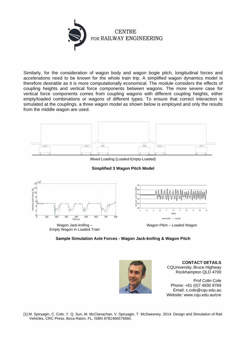
Similarly, for the consideration of wagon body and wagon bogie pitch, longitudinal forces and accelerations need to be known for the whole train trip. A simplified wagon dynamics model is therefore desirable as it is more computationally economical. The module considers the effects of coupling heights and vertical force components between wagons. The more severe case for vertical force components comes from coupling wagons with different coupling heights, either empty/loaded combinations or wagons of different types. To ensure that correct interaction is simulated at the couplings, a three wagon model as shown below is employed and only the results from the middle wagon are used.
Mixed Loading (Loaded-Empty-Loaded)
Simplified 3 Wagon Pitch Model
Wagon Jack-knifing – Empty Wagon in Loaded Train
Wagon Pitch – Loaded Wagon
Sample Simulation Axle Forces - Wagon Jack-knifing & Wagon Pitch
[1] M. Spiryagin, C. Cole, Y. Q. Sun, M. McClanachan, V. Spiryagin, T. McSweeney. 2014. Design and Simulation of Rail
Vehicles, CRC Press, Boca Raton, FL, ISBN 9781466575660.
0 100 200 300 400 500 600 700 8000
2
4
6
8
10
12
14x 10
4
Time (s)
Ver
tical
axl
e fo
rce
(N)
CONTACT DETAILS CQUniversity,Bruce Highway
Rockhampton QLD 4700
Prof Colin Cole Phone: +61 (0)7 4930 9769
Email: [email protected] Website: www.cqu.edu.au/cre
Wagon Dynamics Simulation
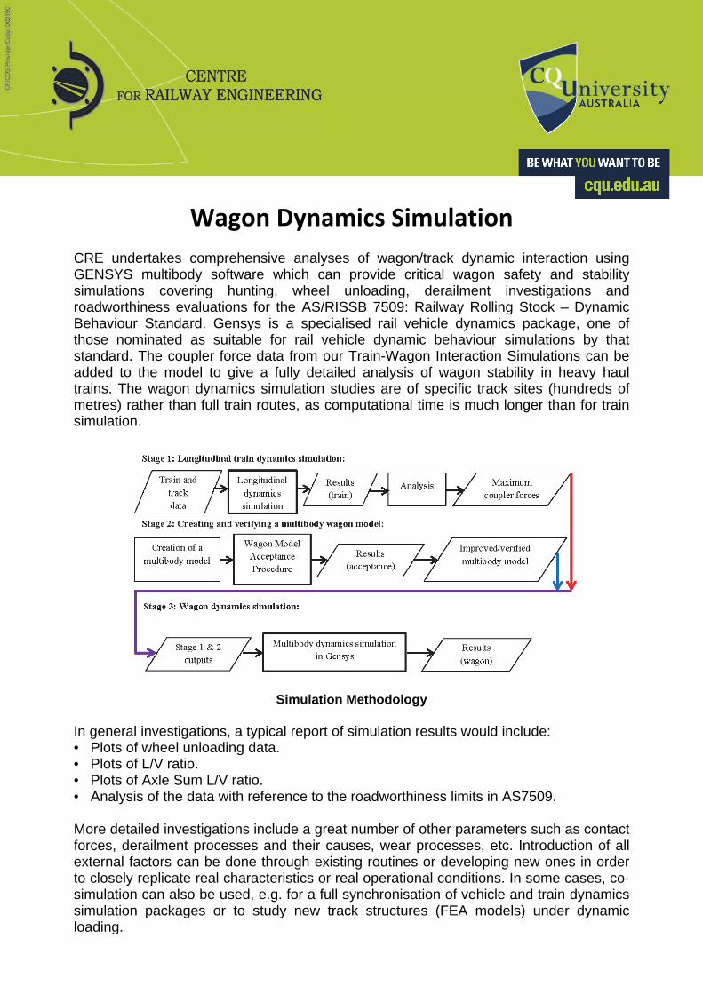
CRE undertakes comprehensive analyses of wagon/track dynamic interaction using GENSYS multibody software which can provide critical wagon safety and stability simulations covering hunting, wheel unloading, derailment investigations and roadworthiness evaluations for the AS/RISSB 7509: Railway Rolling Stock – Dynamic Behaviour Standard. Gensys is a specialised rail vehicle dynamics package, one of those nominated as suitable for rail vehicle dynamic behaviour simulations by that standard. The coupler force data from our Train-Wagon Interaction Simulations can be added to the model to give a fully detailed analysis of wagon stability in heavy haul trains. The wagon dynamics simulation studies are of specific track sites (hundreds of metres) rather than full train routes, as computational time is much longer than for train simulation.
Simulation Methodology
In general investigations, a typical report of simulation results would include: • Plots of wheel unloading data. • Plots of L/V ratio. • Plots of Axle Sum L/V ratio. • Analysis of the data with reference to the roadworthiness limits in AS7509. More detailed investigations include a great number of other parameters such as contact forces, derailment processes and their causes, wear processes, etc. Introduction of all external factors can be done through existing routines or developing new ones in order to closely replicate real characteristics or real operational conditions. In some cases, co-simulation can also be used, e.g. for a full synchronisation of vehicle and train dynamics simulation packages or to study new track structures (FEA models) under dynamic loading.
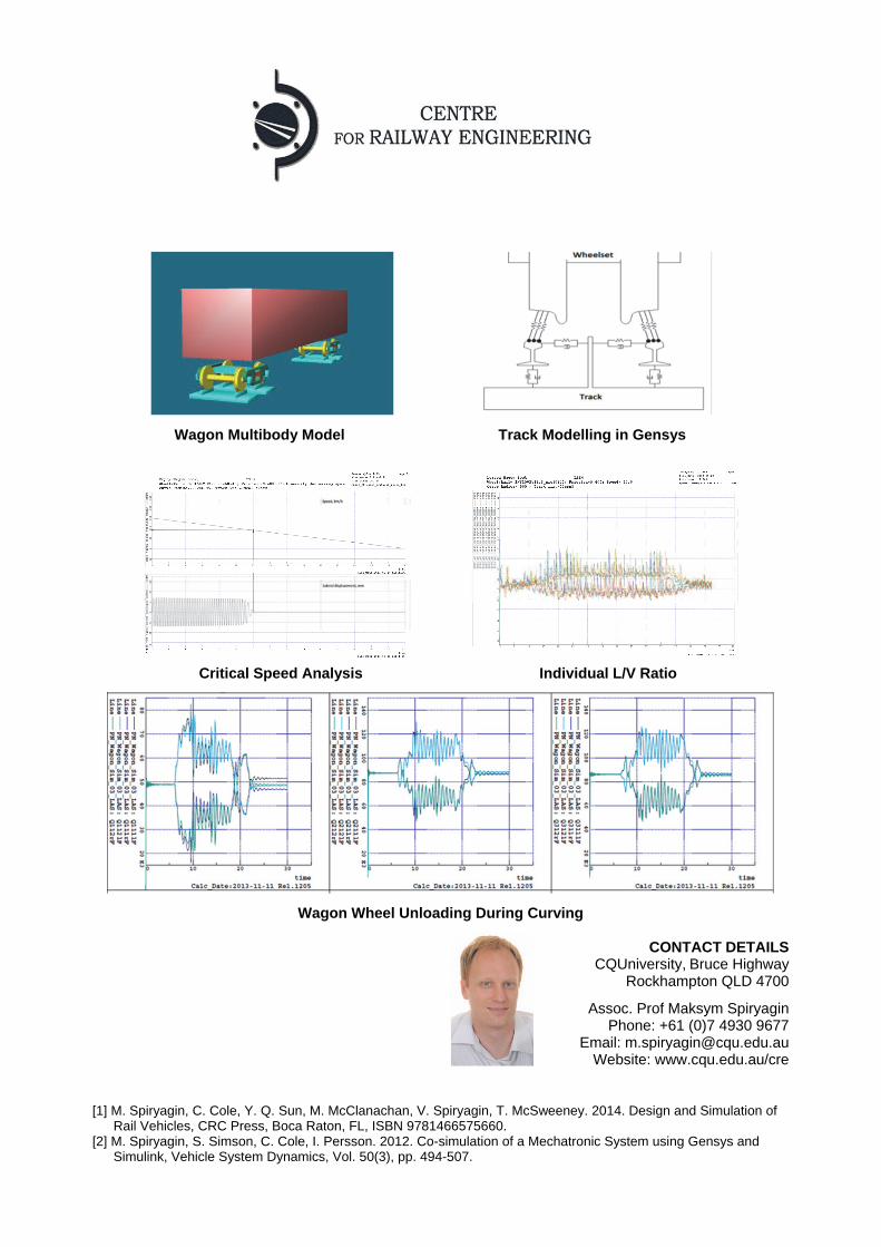
Wagon Multibody Model Track Modelling in Gensys
Critical Speed Analysis Individual L/V Ratio
Wagon Wheel Unloading During Curving
CONTACT DETAILS CQUniversity,Bruce Highway
Rockhampton QLD 4700
Assoc. Prof Maksym Spiryagin Phone: +61 (0)7 4930 9677
Email: [email protected] Website: www.cqu.edu.au/cre
[1] M. Spiryagin, C. Cole, Y. Q. Sun, M. McClanachan, V. Spiryagin, T. McSweeney. 2014. Design and Simulation of
Rail Vehicles, CRC Press, Boca Raton, FL, ISBN 9781466575660. [2] M. Spiryagin, S. Simson, C. Cole, I. Persson. 2012. Co-simulation of a Mechatronic System using Gensys and
Simulink, Vehicle System Dynamics, Vol. 50(3), pp. 494-507.
Locomotive Traction Dynamics & Co‐Simulation
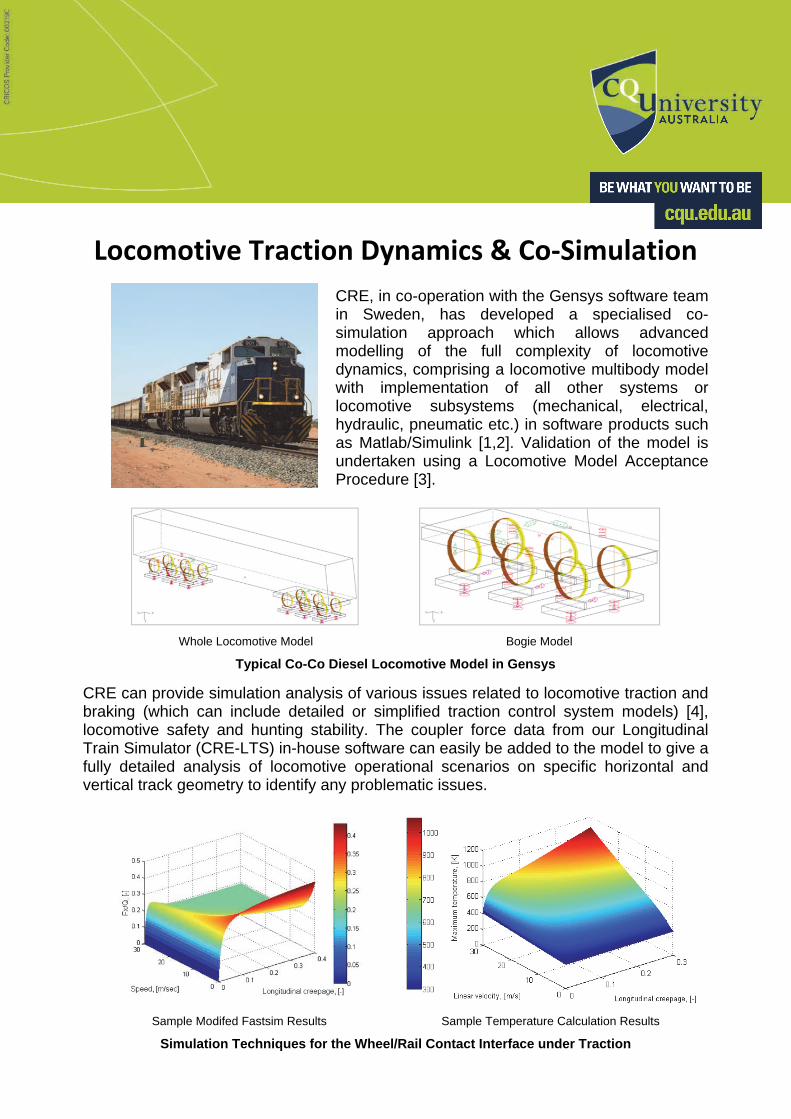
CRE, in co-operation with the Gensys software team in Sweden, has developed a specialised co-simulation approach which allows advanced modelling of the full complexity of locomotive dynamics, comprising a locomotive multibody model with implementation of all other systems or locomotive subsystems (mechanical, electrical, hydraulic, pneumatic etc.) in software products such as Matlab/Simulink [1,2]. Validation of the model is undertaken using a Locomotive Model Acceptance Procedure [3].
Whole Locomotive Model Bogie Model
Typical Co-Co Diesel Locomotive Model in Gensys
CRE can provide simulation analysis of various issues related to locomotive traction and braking (which can include detailed or simplified traction control system models) [4], locomotive safety and hunting stability. The coupler force data from our Longitudinal Train Simulator (CRE-LTS) in-house software can easily be added to the model to give a fully detailed analysis of locomotive operational scenarios on specific horizontal and vertical track geometry to identify any problematic issues.
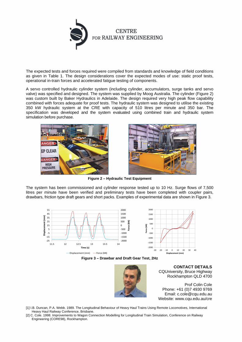
Sample Modifed Fastsim Results Sample Temperature Calculation Results
Simulation Techniques for the Wheel/Rail Contact Interface under Traction

The results obtained can be transferred to FEA or other programs in order to obtain more detailed information on the interaction processes between wheels and rails under traction and braking modes, the consequent stresses and temperatures, etc. [5]. Different wheel and rail profiles can also be considered.
Having more information on whether or not a new or modified locomotive would satisfy both static and dynamic behaviour requirements would be advantageous in the preliminary design stage. Some Australian and European standards also allow simulation in place of physical tests which can significantly reduce the cost of compliance validation.
Sample Wheel Tread Contact Simulation Results: Lateral Contact Patch Forces
Sample Wheel Flange Contact Simulation Results: Lateral Contact Patch Forces
CONTACT DETAILS
CQUniversity,Bruce Highway Rockhampton QLD 4700
Assoc. Prof Maksym Spiryagin Phone: +61 (0)7 4930 9677
Email: [email protected]
Website: www.cqu.edu.au/cre [1] M. Spiryagin, C. Cole, Y. Q. Sun, M. McClanachan, V. Spiryagin, T. McSweeney. 2014. Design and Simulation of
Rail Vehicles, CRC Press, Boca Raton, FL, ISBN 9781466575660. [2] M. Spiryagin, S. Simson, C. Cole, I. Persson. 2012. Co-simulation of a Mechatronic System using Gensys and
Simulink, Vehicle System Dynamics, Vol. 50(3), pp. 494-507. [3] M. Spiryagin, A. George, Y.Q. Sun, C. Cole, T. McSweeney, S. Simson. 2013. Investigation of Locomotive
Multibody Modelling Issues and Results Assessment Based on the Locomotive Model Acceptance Procedure, Journal of Rail and Rapid Transit, Vol. 227(5), pp. 453-468.
[4] M. Spiryagin, P. Wolfs, F. Szanto, C. Cole. 2015. Simplified and advanced modelling of traction control systems of heavy-haul locomotives,Vehicle System Dynamics, Vol. 53(5), pp. 672-691.
[5] C. Cole, M. Spiryagin, Y.Q. Sun, K.D. Vo, K.A. Tieu, H. Zhu, P. Meehan. 2013. R3.119: Locomotive Adhesion: Final Report, CRC for Rail Innovation, Brisbane, Australia.

Heavy Haul Draft Gear Testing
The CRE has designed and built a laboratory rig to emulate field conditions for draft gears and allow proof tests and accelerated fatigue tests. The design process allowed for expected forces from heavy haul train operations and included provision for hardware-in-the-loop investigations using train simulation software to provide inputs and test sequences. The rig has been made large enough to include a wagon stub sill and a coupler pair (or drawbar) so that all draft gear components (knuckle, coupler, yoke, draft gear and stub sill) can be evaluated simultaneously as shown in Figure 1.
Figure 1 – Test Rig showing Stub Sill and Couplers
Longitudinal train dynamics and large in-train forces have become a key focus for designers and operators of modern heavy haul rollingstock. The function of draft gears of providing damping of in-train forces while having sufficient strength to withstand heavy haul in-train forces continues to require optimisation. The challenge faced when seeking to achieve this is that not enough is known about draft gear behaviour. Current draft gear designs are accepted based on drop hammer tests. These tests are primarily to establish the robustness of the mechanical design and damping performance. It has been shown in previous studies [1,2] that the conditions of operation of draft gears in service and their actual behaviour are much different to that emulated by drop hammer tests. So, while drop hammer tests are important in establishing performance at extremes, a full load spectrum is needed from field tests to analyse draft gear performance. As field performance depends on design, an iterative optimisation process using field data is quite impossible (i.e., this could require a roll out of prototype batches of 400 draft gears per design test). Design optimisation therefore needs a more practical approach – a laboratory rig that can emulate realistic heavy haul train conditions. A laboratory rig with loading capabilities of up to 4.4MN in buff and 3.5MN in draft at loading rates sufficient for in-train force impacts has been installed at the CRE in partnership with Bradken Pty Ltd and with funding from the Queensland Department of Science, Information Technology and Innovation. The hydraulic loading cylinder has a stroke of 300mm and a maximum speed of 1m/s.
Table 1 – Test Specifications
TestDescription Movement(Stroke)mm
MaxForceDraftMN
MaxForceBuffMN
AARStandard
1 TrainSimulation[a],Hardware‐in‐theLoop 180[b] 3.1[c] 3.1[c]2 FatigueTests[d]‐WholeDrawgear 10to75 3.1[d] 3.1[d]3 KnuckleYield
CouplerBody,YokeYield 1.8
3.1,3.3
3.1,3.3M‐211
M‐211,M‐2054 KnuckleUltimate
CouplerBody,YokeUltimate 2.9
4.0,4.0
4.0,4.0M‐211
M‐211,M‐205
[a] In-Train behaviour has a mix of impacts and steady loads. [b] This is based on a half model of a wagon connection – one draft gear plus 25mm slack – full compression/tension cycle (~77mm*2+25mm). [c] Based on coupler yield. [d] Based on supplied Spectra, excludes the draft gear.
The expected tests and forces required were compiled from standards and knowledge of field conditions as given in Table 1. The design considerations cover the expected modes of use: static proof tests, operational in-train forces and accelerated fatigue testing of components. A servo controlled hydraulic cylinder system (including cylinder, accumulators, surge tanks and servo valve) was specified and designed. The system was supplied by Moog Australia. The cylinder (Figure 2) was custom built by Baker Hydraulics in Adelaide. The design required very high peak flow capability combined with forces adequate for proof tests. The hydraulic system was designed to utilise the existing 350 kW hydraulic system at the CRE with capacity of 510 litres per minute and 350 bar. The specification was developed and the system evaluated using combined train and hydraulic system simulation before purchase.
Figure 2 – Hydraulic Test Equipment
The system has been commissioned and cylinder response tested up to 10 Hz. Surge flows of 7,500 litres per minute have been verified and preliminary tests have been completed with coupler pairs, drawbars, friction type draft gears and short packs. Examples of experimental data are shown in Figure 3.
Figure 3 – Drawbar and Draft Gear Test, 2Hz
[1] I.B. Duncan, P.A. Webb. 1989. The Longitudinal Behaviour of Heavy Haul Trains Using Remote Locomotives, International
Heavy Haul Railway Conference, Brisbane. [2] C. Cole. 1998. Improvements to Wagon Connection Modelling for Longitudinal Train Simulation, Conference on Railway
Engineering (CORE98), Rockhampton.
‐2000
‐1500
‐1000
‐500
0
500
1000
1500
2000
‐25
‐15
‐5
5
15
25
35
45
55
11.5 12 12.5 13 13.5 14
Force (kN)
Displacement (m
m)
Time (s)
Displacement (mm) Force (kN)
‐2000
‐1500
‐1000
‐500
0
500
1000
1500
2000
‐30 ‐20 ‐10 0 10 20 30 40
Force (kN
)
Displacement (mm)
CONTACT DETAILS CQUniversity,Bruce Highway
Rockhampton QLD 4700
Prof Colin Cole Phone: +61 (0)7 4930 9769
Email: [email protected] Website: www.cqu.edu.au/cre
Rail Stress Analysis
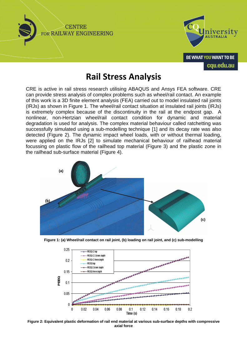
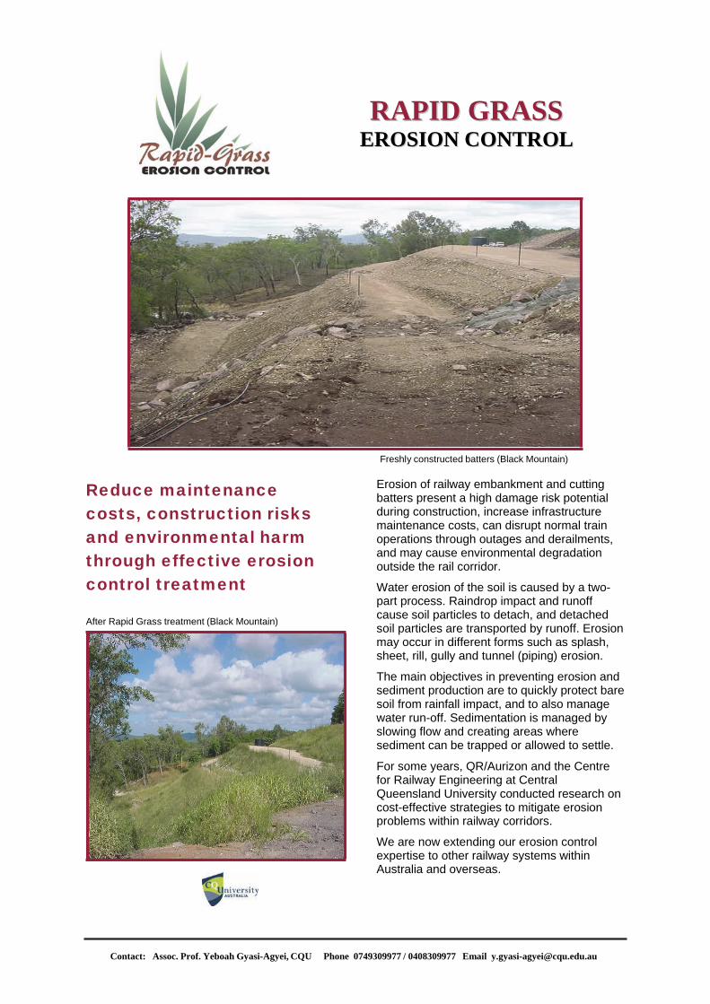
CRE is active in rail stress research utilising ABAQUS and Ansys FEA software. CRE can provide stress analysis of complex problems such as wheel/rail contact. An example of this work is a 3D finite element analysis (FEA) carried out to model insulated rail joints (IRJs) as shown in Figure 1. The wheel/rail contact situation at insulated rail joints (IRJs) is extremely complex because of the discontinuity in the rail at the endpost gap. A nonlinear, non-Hertzian wheel/rail contact condition for dynamic and material degradation is used for analysis. The complex material behaviour called ratchetting was successfully simulated using a sub-modelling technique [1] and its decay rate was also detected (Figure 2). The dynamic impact wheel loads, with or without thermal loading, were applied on the IRJs [2] to simulate mechanical behaviour of railhead material focussing on plastic flow of the railhead top material (Figure 3) and the plastic zone in the railhead sub-surface material (Figure 4).
Figure 1: (a) Wheel/rail contact on rail joint, (b) loading on rail joint, and (c) sub-modelling
Figure 2: Equivalent plastic deformation of rail end material at various sub-surface depths with compressive
axial force
(c)
(a)
(b)

Figure 3: Plastic flow in longitudinal direction Figure 4: Sub-surface plastic deformation
A sensitivity analysis of IRJ endpost thickness [3] and endpost material [4] was also carried out and FEA simulation results were verified using CRE testing facilities and field data. Extension of 3D FEA modelling to facilitate the redesign of joint bars to improve fatigue life by incorporating a saddle design, analysis of optimum wheel/rail profiles incorporating material relocation by plastic deformation, and condition monitoring assessment of railway structures using FEA and vibration data is progressing. An adapting meshing technique is also currently being investigated for improving FEA results. Adaptive meshing allows ABAQUS to maintain a high-quality mesh throughout an analysis by allowing the mesh to move independently of the material. It does not alter the topology of the mesh. This type of adaptive meshing is often referred to as Arbitrary Lagrangian-Eulerian (ALE) analysis as it combines the features of pure Lagrangian analysis and Eulerian analysis.
CONTACT DETAILS CQUniversity,Bruce Highway
Rockhampton QLD 4700
Dr Nirmal Mandal Phone: +61 (0)7 4923 2064
Email: [email protected] Website: www.cqu.edu.au/cre
[1] N.K. Mandal, M. Dhanasekar. 2013. Sub-modelling for the ratchetting failure of insulated rail joints, International
Journal of Mechanical Science, 75, 110-122. [2] N.K. Mandal. 2015. Plastic ratchetting of railhead material in the vicinity of insulated rail joints with wheel and
thermal loads, Wear, 330-331, pp. 540-553. [3] N.K. Mandal. 2014. Ratchetting of railhead material of insulated rail joints (IRJs) with reference to endpost
thickness, Engineering Failure Analysis, 45, pp. 347-362. [4] N.K. Mandal. 2016. Finite Element Analysis on mechanical behaviour of insulated rail joints due to impact loadings,
Journal of Rail and Rapid Transit, 230, pp. 759-773.
Contact: Assoc. Prof. Yeboah Gyasi-Agyei, CQU Phone 0749309977 / 0408309977 Email [email protected]
Reduce maintenance costs, construction risks and environmental harm through effective erosion control treatment
After Rapid Grass treatment (Black Mountain)
RRAAPPIIDD GGRRAASSSS EERROOSSIIOONN CCOONNTTRROOLL
Freshly constructed batters (Black Mountain)
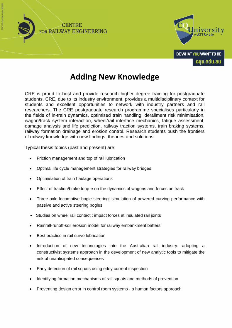
Erosion of railway embankment and cutting batters present a high damage risk potential during construction, increase infrastructure maintenance costs, can disrupt normal train operations through outages and derailments, and may cause environmental degradation outside the rail corridor.
Water erosion of the soil is caused by a two- part process. Raindrop impact and runoff cause soil particles to detach, and detached soil particles are transported by runoff. Erosion may occur in different forms such as splash, sheet, rill, gully and tunnel (piping) erosion.
The main objectives in preventing erosion and sediment production are to quickly protect bare soil from rainfall impact, and to also manage water run-off. Sedimentation is managed by slowing flow and creating areas where sediment can be trapped or allowed to settle.
For some years, QR/Aurizon and the Centre for Railway Engineering at Central Queensland University conducted research on cost-effective strategies to mitigate erosion problems within railway corridors.
We are now extending our erosion control expertise to other railway systems within Australia and overseas.

Contact: Assoc. Prof. Yeboah Gyasi-Agyei, CQU Phone 0749309977 / 0408309977 Email [email protected]
RAPID GRASS EROSION CONTROL TREATMENT
Before and after rehabilitation (Boundary Hill)
We will analyse your specific erosion problems and design a strategic erosion control plan customised to your local conditions. Erosion control processes can involve some or all of the following:
Topsoiling or amelioration of the surface soil with lime or gypsum where it is established that the surface soil is dispersive, sodic, saline and/or has an extreme pH.
Fertilisers spread to provide a medium conducive to rapid growth of grasses.
Cheap mulch (waste ballast) or erosion control blankets are spread or laid to protect grass seeds/ seedlings and ameliorants from washout by high intensity and short duration rainfall.
Grass seeding with non-pest species that are fast growing and accepting of local conditions.
A cost effective drip irrigation system to aid grass establishment is an integral part of the erosion control process options; the choice of water source depends on availability and cost.
In order to reduce the treatment costs, the embankment and cutting batters may be categorised with different levels of treatment.
Rapid Grass processes will give your company the opportunity to secure a cost effective and sustainable method of erosion control to remain financially viable in an environmentally conscious future.
KEY BENEFITS OF RAPID GRASS EROSION CONTROL:
Minimisation of maintenance costs
Minimisation of interruptions to normal train operations
Minimisation of the risks of moisture and erosion induced formation failures and associated outages or derailments
Minimisation of failures of railway signalling systems due to fouling of ballast by sediment
Aesthetically pleasing batters and surrounds will enhance your company’s image
Minimisation of the risk of lawsuits resulting from sediment delivery from your easements to nearby water courses (e.g. creeks, stock ponds)
Compliance with environmental legislative requirements

GENSYS Software Capabilities
Possible analyses include wheel unloading on twisted track, wagon body roll, critical speed, pantograph sway, maximum track shift forces and flange climb ratio, vehicle overturning, ride comfort, motion sickness, wheel and rail wear rates, vehicle behaviour under traction and braking, predicting if the wheel-profile will be stable or not and the risk of developing out of round wheels.
To simplify the generation of input data, the GENSYS package contains the following pre-processors: TRACK for generation of track irregularity files from track recording car measurements, KPF for generation of wheel-rail geometrical properties from measured or designed wheel and rail profiles, MISC for processing miscellaneous file formats, NPICK for adding flexible modes to rigid bodies, and OPTI which allows the user to set various criteria/options and sequences of calculations.
The main calculation programs in GENSYS are QUASI for quasi-static analysis, MODAL for modal analysis, FRESP for frequency-response analysis and TSIM for time-domain integration. All four calculation programs are very general in their basic design. With the GENSYS input data syntax, it is easy to create models of mechatronic systems. If the mechatronic electronic system is already written in an m-file for Matlab or Octave, it is possible to initiate a co-simulation with the cosim_server command.
GENSYS includes three powerful postprocessors: GLPLOT, GPLOT and MPLOT. GPLOT is a 3-D visualisation and animation program. GPLOT can also display a visual animation of the progression of wheel/rail-contact conditions. GLPLOT is similar to GPLOT but is written in OpenGL to give a cleaner appearance. The model is shown in perspective and all masses are made of solid and/or transparent surfaces. MPLOT is used for post-processing and 2- or 3-dimensional plotting of results, consisting of curves and/or scalars. Post-processing in MPLOT consists of algebraic operations, filtering operations, Fourier transform operations, different ride comfort assessments and various statistical evaluation methods.
CRE-LTS Longitudinal Train Simulator Software
Extensive train test programs, dating back to 1994, allowed CRE to develop and validate a fully longitudinal train simulation for engineering analysis: the Centre for Railway Engineering – Longitudinal Train Simulator (CRE-LTS). The software has the usual train simulation tools plus many improved capabilities to facilitate research. It contains detailed wagon connection modelling, coupler angle calculation, virtual driver software for automated simulation studies, force REPOS data output for fatigue studies, and energy analysis capability. There are no limits on rollingstock types or train marshalling configurations and simulations can be synchronised with field data of various formats
CONTACT DETAILS CQUniversity, Bruce Highway
Rockhampton QLD 4700
Assoc Prof Maksym Spiryagin Phone +61 (0)7 4930 9677
Email [email protected]
Website www.cqu.edu.au/cre
[1] M. Spiryagin, C. Cole, Y. Q. Sun, M. McClanachan, V. Spiryagin, T. McSweeney. 2014. Design and Simulation of Rail Vehicles, CRC Press, Boca Raton, FL, ISBN 9781466575660.
World Class Simulation of ANY Railway Operational Scenario
If a railway can do it, CRE can simulate it with GENSYS and CRE-LTS.
Locomotive/Wagon Dynamics Longitudinal Train Dynamics
Track Defects & Irregularities Braking & Traction
CRE is active in simulation research and continually strives to implement innovative new developments in modelling railway operational scenarios. GENSYS is a complete software tool for railway vehicle analysis, but its original design in Sweden as a general three-dimensional multibody dynamic software package allows modelling of many mechanical, electrical and/or mathematical problems. CRE’s in-house Longitudinal Train Simulator (CRE-LTS) software has the usual train simulation tools plus many improved capabilities to facilitate detailed analysis of railway operational scenarios.

AB DEsolver, Optand 914, S‐831 92 Ostersund, SWEDEN Centre for Railway Engineering, CQUniversity, Rockhampton, AUSTRALIA
Cooking with GENSYS & CRE-LTS [1] Use CRE-LTS to model in-train forces and motions, allowing for traction,
braking, gradients, curvature and retardation/drag. Outputs are coupler forces and coupler angles for selected wagons which are required for subsequent multibody simulations.
Develop and verify a multibody dynamics model of railway vehicles connected to each other by coupling elements. Each vehicle comprises a body with bogie frames and wheelsets, all having roll/pitch/yaw and longitudinal/lateral/vertical degrees of freedom. Checks are made to verify the model, including against the Locomotive/Wagon Model Acceptance Procedures (LMAP and WMAP).
Use the verified vehicle model/s in GENSYS to undertake a comprehensive dynamic simulation. Lateral coupler forces are applied at front and rear couplers; these forces change with respect to track geometry and longitudinal train dynamics as the train proceeds. The simulations are run over your actual track geometry (horizontal and vertical) and outputs include cycle times, energy used, coupler forces, wheel unloading, individual wheel L/V and sum L/V axle ratios to determine the economics and safety of the proposed operation.
Co-simulation network interface

Publishing Research
CRE has a strong track record in publishing research that can be released to the public domain. Publications serve two purposes: the dissemination of information to keep the rail industry informed, and a means of benchmarking the quality and rigour of our work by means of peer review when papers are submitted to world class journals. In the recent ERA rankings in Australia, the publication collection in Mechanical Engineering at CQUniversity was ranked above World Class.
Publications during 2014 and 2015 include:
Title Authors
Advanced dynamic modelling for friction draft gears Q Wu; M Spiryagin; C Cole.
Application of flywheel energy storage for heavy haul locomotives M Spiryagin; P Wolfs;
F Szanto; Y.Q Sun; C Cole,
D Nielsen.
Computing schemes for longitudinal train dynamics sequential, parallel and hybrid Q Wu; C Cole.
Determination of dynamic characteristics of draft gears of heavy haul train using collision simulations
Y.Q Sun; Q Wu; M Spiryagin;
C Cole.
FEA to assess railhead material damage with a reference to nylon endpost material of insulated rail joints
N.K Mandal.
Implementation of the temperature calculation model in a multibody code for the investigation of frictional heating processes at the wheel-rail interface for heavy haul locomotives
M Spiryagin; K Duan; Q Wu;
C Cole; Y.Q Sun; I Persson.
Investigation of the application of adjustable air suspension under traction control for heavy haul locomotives
M Spiryagin; V Spiryagin;
P Wolfs; C Cole; Y.Q Sun;
I Persson
Longitudinal train dynamics during indexer train unloading operations C Cole; Y.Q Sun; M Spiryagin.
Modelling of traction in railway vehicles M Spiryagin; P Wolfs; C Cole.
Monitoring vertical wheel–rail contact forces based on freight wagon inverse modelling
Y.Q Sun; C Cole; M Spiryagin.
Plastic ratchetting of railhead material in the vicinity of insulated rail joints with wheel and thermal loads
N.K Mandal.
Prediction of wheel-rail contact forces based on a heavy haul locomotive dynamic inverse modelling
YQ Sun; M Spiryagin; C Cole.
Simplified and advanced modelling of traction control systems of heavy-haul locomotives
M Spiryagin; P Wolfs;
F Szanto; C Cole.
Simulation of slow speed wagon dynamics and curve wear on balloon loops D Nielsen; M Spiryagin;
YQ Sun; C Cole.
Wagon dynamics from a combination of faults and external forces M Spiryagin; Q; YQ Sun;
C Cole.
Wagon multibody model and its real-time application M Spiryagin; S.S Ahmad;
C Cole; Y.Q Sun;
T McSweeney.
Wheel-rail wear investigation on a balloon loop track through simulation of slow speed wagon dynamics
Y.Q Sun; M Spiryagin; C Cole;
D Nielsen.
Adhesion estimation and its implementation for traction control of locomotives M Spiryagin; C Cole; Y.Q Sun.
Assessing wagon curve stability in heavy haul trains C Cole; Y.Q Sun; M Spiryagin.
Design and simulation of rail vehicles M Spiryagin; C Cole, Colin;
Y.Q Sun; M McClanachan;
V Spiryagin; T McSweeney.
A dynamic model of friction draft gear Q Wu; M Spiryagin; C Cole.
Finite element analysis of the mechanical behaviour of insulated rail joints due to impact loadings
N.K Mandal.
Integrated methodology for investigation of wagon bogie concepts by simulation S.S Ahmad; C Cole;
M Spiryagin; Y.Q Sun.
Integrated methodology for investigation of wagon design concepts by simulations S.S Ahmad; C Cole;
M Spiryagin; Y.Q Sun.
Longitudinal dynamics and energy analysis for heavy haul trains Q Wu; S Luo; C Cole.
Longitudinal heavy haul train simulations and energy analysis for typical Australian track routes
Y.Q Sun; C Cole; M Spiryagin;
T Godber; S Hames; M Rasul.
Maintenance intervention optimisation for existing railway bridges D Nielsen; T McSweeney;
D Raman.
Methodology for optimization of friction draft gear design Q Wu; C Cole; M Spiryagin.
Modelling grass-cover effects on soil erosion on railway embankment steep slopes A.K Sajjan; Y Gyasi-Agyei;
R.H Sharma.
On the low cycle fatigue failure of insulated rail joints (IRJs) N.K Mandal.
Optimisation of maintenance interventions for railway bridges D Nielsen; R Egelstaff;
T McSweeney.
Parametric studies on crashworthiness of Australian rolling stocks using multi-body dynamics modelling
Y.Q Sun; C Cole; M Spiryagin;
M Dhanasekar.
Ratchetting of railhead material of insulated rail joints (IRJs) with reference to endpost thickness
N.K Mandal.
Reduction of low frequency linear vibrations, long heavy haul consists D Birkin; C Cole; C Bosomworth
Research methodology for evaluation of top-of-rail friction management in Australian heavy haul networks
M Spiryagin; M Sajjad;
D Nielsen; Y.Q Sun, D Raman;
G Chattopadhyay.
A review of dynamics modelling of friction draft gear Q Wu; C Cole; S Luo;
M Spiryagin.
A review of dynamics modelling of friction wedge suspensions Q Wu; C Cole; M Spiryagin;
Y.Q Sun.
Stabilising mechanism and running behaviour of couplers on heavy haul trains Z Xu; Q Wu; S Luo; W Ma;
X Dong.
CONTACT DETAILS CQUniversity Bruce Highway Rockhampton QLD 4700
Enquiries: Ms Vicky Kreiser Phone: +61 (0)7 4923 2277 Email: [email protected]
Website: www.cqu.edu.au/cre
Adding New Knowledge
CRE is proud to host and provide research higher degree training for postgraduate students. CRE, due to its industry environment, provides a multidisciplinary context for students and excellent opportunities to network with industry partners and rail researchers. The CRE postgraduate research programme specialises particularly in the fields of in-train dynamics, optimised train handling, derailment risk minimisation, wagon/track system interaction, wheel/rail interface mechanics, fatigue assessment, damage analysis and life prediction, railway traction systems, train braking systems, railway formation drainage and erosion control. Research students push the frontiers of railway knowledge with new findings, theories and solutions. Typical thesis topics (past and present) are:
Friction management and top of rail lubrication
Optimal life cycle management strategies for railway bridges
Optimisation of train haulage operations
Effect of traction/brake torque on the dynamics of wagons and forces on track
Three axle locomotive bogie steering: simulation of powered curving performance with
passive and active steering bogies
Studies on wheel rail contact : impact forces at insulated rail joints
Rainfall-runoff-soil erosion model for railway embankment batters
Best practice in rail curve lubrication
Introduction of new technologies into the Australian rail industry: adopting a
constructivist systems approach in the development of new analytic tools to mitigate the
risk of unanticipated consequences
Early detection of rail squats using eddy current inspection
Identifying formation mechanisms of rail squats and methods of prevention
Preventing design error in control room systems - a human factors approach
Socio-technical analysis of railway level crossing designs for pedestrian use
Investigation of traction forces from high adhesion locomotives
Human factors engineering in signal sighting and signal recognition
Affordable level crossing protection systems
An optimised friction management strategy for the wheel-rail interface of heavy haul
railways
Optimisation of draft gear designs and wagon connection systems for heavy haul trains
Hybrid of fuzzy logic controllers with bio-inspired optimisation techniques to solve an
inventory control model with different demand rate and multi-echelon system
Innovative wagon and bogie designs to improve economics of inter-modal rail
transportation
Evaluation and modelling performance of capping layer in rail track substructure
Algorithms and modelling for enhanced real time monitoring systems for freight wagons
Derailment risk assessment
Alternate concept wagons
Future locomotive power technologies
Train systems energy analysis
Wagon stability analysis
CONTACT DETAILS CQUniversity Bruce Highway Rockhampton QLD 4700
Enquiries: Ms Vicky Kreiser Phone: +61 (0)7 4923 2277 Email: [email protected]
Director : Prof Colin Cole Phone: +61 (0)7 4930 9769 Email: [email protected]
Deputy Director: A/Prof Maksym Spiryagin Phone: +61 (0)7 4930 9677 Email: [email protected]
Website: www.cqu.edu.au/cre

Intelligent Instruments
CRE has extensive experience in data acquisition and data processing. Indeed, with the “Internet of Things” and lower cost of transducers, it has never been easier to collect and store data. The problem is, having obtained the data, how do you make sure you see the important reports? What about maintenance – are there alternatives to having thousands of transducers to maintain? The solution can be found in Intelligent Instruments. These are instruments that do not just measure; rather they process and simulate data on-board to give much more useful and valuable information to the control systems and the driver– and at lower cost. Examples of past projects include: Intelligent Train Monitor (ITM) The ITM is a package of instrumentation and software that gives the train driver comprehensive feedback of in-train forces on a screen in the locomotive cabin. Intelligent algorithms provide comprehensive reporting of train dynamics states based only on the locomotive conditions, GPS and track databases. The innovation is unique in that the device is also able to give real time predictions of in-train forces and train speed for the next 50 seconds of operation. This allows both future speed and in-train force levels to be used to modify control settings to improve compliance with speed limits and decrease in-train force levels.
ITM Screen
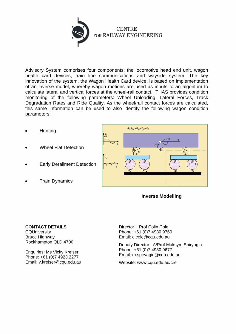
Train Health Advisory System (THAS) THAS is based on simple, inexpensive devices installed across a fleet of wagons, with an intelligent device located in the locomotive of a train. Moving the intelligence to a single point on the train reduces costs significantly as the devices on individual wagons are then simpler in design. The development ensures easy maintainability by keeping wiring and instrumentation only on the wagon body. The Train Health
x
z
roll
yaw
a
t
t
ay, az, zyx ,,
LV
Advisory System comprises four components: the locomotive head end unit, wagon health card devices, train line communications and wayside system. The key innovation of the system, the Wagon Health Card device, is based on implementation of an inverse model, whereby wagon motions are used as inputs to an algorithm to calculate lateral and vertical forces at the wheel-rail contact. THAS provides condition monitoring of the following parameters: Wheel Unloading, Lateral Forces, Track Degradation Rates and Ride Quality. As the wheel/rail contact forces are calculated, this same information can be used to also identify the following wagon condition parameters: Hunting
Inverse Modelling
Wheel Flat Detection Early Derailment Detection Train Dynamics
CONTACT DETAILS CQUniversity Bruce Highway Rockhampton QLD 4700 Enquiries: Ms Vicky Kreiser Phone: +61 (0)7 4923 2277 Email: [email protected]
Director : Prof Colin Cole Phone: +61 (0)7 4930 9769 Email: [email protected]
Deputy Director: A/Prof Maksym Spiryagin Phone: +61 (0)7 4930 9677 Email: [email protected]
Website: www.cqu.edu.au/cre
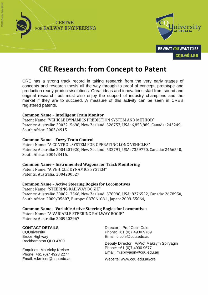
CRE Research: from Concept to Patent CRE has a strong track record in taking research from the very early stages of concepts and research thesis all the way through to proof of concept, prototype and production ready products/solutions. Great ideas and innovations start from sound and original research, but must also enjoy the support of industry champions and the market if they are to succeed. A measure of this activity can be seen in CRE’s registered patents. CommonName–IntelligentTrainMonitorPatentName:“VEHICLEDYNAMICSPREDICTIONSYSTEMANDMETHOD”Patents:Australia:2002215698,NewZealand:526757,USA:6,853,889,Canada:243249,SouthAfrica:2003/4915CommonName–FuzzyTrainControlPatentName:“ACONTROLSYSTEMFOROPERATINGLONGVEHICLES”Patents:Australia:2004201920,NewZealand:532791,USA:7359770,Canada:2466540,SouthAfrica:2004/3416.CommonName–InstrumentedWagonsforTrackMonitoringPatentName:“AVEHICLEDYNAMICSSYSTEM”Patents:Australia:2004200527CommonName–ActiveSteeringBogiesforLocomotivesPatentName:“STEERINGRAILWAYBOGIE”Patents:Australia:2008217566,NewZealand:578998,USA:8276522,Canada:2678950,SouthAfrica:2009/05607,Europe:08706108.1,Japan:2009‐55064,CommonName–VariableActiveSteeringBogiesforLocomotivesPatentName:“AVARIABLESTEERINGRAILWAYBOGIE”Patents:Australia:2009202967 CONTACT DETAILS CQUniversity Bruce Highway Rockhampton QLD 4700 Enquiries: Ms Vicky Kreiser Phone: +61 (0)7 4923 2277 Email: [email protected]
Director : Prof Colin Cole Phone: +61 (0)7 4930 9769 Email: [email protected]
Deputy Director: A/Prof Maksym Spiryagin Phone: +61 (0)7 4930 9677 Email: [email protected]
Website: www.cqu.edu.au/cre