introduction hardware setup bios setupstatic.highspeedbackbone.net/pdf/abit_sg-95_manual.pdf ·...
TRANSCRIPT
Intro
du
ction
Hard
ware S
etup
BIO
S S
etup
D
river & U
tility CD
A
pp
end
ix
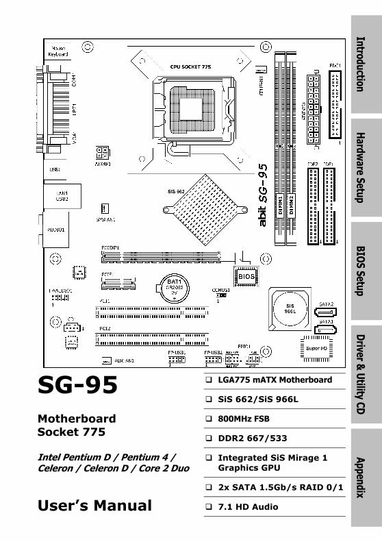
SG-95
Motherboard
Socket 775
Intel Pentium D / Pentium 4 /
Celeron / Celeron D / Core 2 Duo
User’s Manual
� LGA775 mATX Motherboard
� SiS 662/SiS 966L
� 800MHz FSB
� DDR2 667/533
� Integrated SiS Mirage 1
Graphics GPU
� 2x SATA 1.5Gb/s RAID 0/1
� 7.1 HD Audio
SG-95
User’s Manual
English, 1st Edition
August, 2006
Copyright and Warranty Notice
The information in this document is subject to change without notice and does not represent a commitment on part of the vendor, who assumes no liability or responsibility for any errors that may appear in this manual.
No warranty or representation, either expressed or implied, is made with respect to the quality, accuracy or fitness for any particular part of this document. In no event shall the manufacturer be liable for direct, indirect, special, incidental or consequential damages arising from any defect or error in this manual or product.
Product names appearing in this manual are for identification purpose only and trademarks and product names or brand names appearing in this document are the property of their respective owners.
This document contains materials protected under International Copyright Laws. All rights reserved. No part of this manual may be reproduced, transmitted or transcribed without the expressed written permission of the manufacturer and authors of this manual.
If you do not properly set the motherboard settings, causing the motherboard to malfunction or fail, we cannot guarantee any responsibility.
ii SG-95
Intro
du
ction
Contents
1. Introduction..................................................................... 1-1
Hard
ware S
etup
BIO
S S
etup
D
river & U
tility CD
A
pp
end
ix
1.1 Features & Specifications .............................................................1-1
1.2 Motherboard Layout.....................................................................1-3
2. Hardware Setup ............................................................... 2-1
2.1 Choosing a Computer Chassis .......................................................2-1
2.2 Installing Motherboard .................................................................2-1
2.3 Checking Jumper Settings ............................................................2-2
2.3.1 CMOS Memory Clearing Header and Backup Battery ..............2-3
2.4 Connecting Chassis Components...................................................2-5
2.4.1 ATX Power Connectors ........................................................2-5
2.4.2 Front Panel Switches & Indicators Headers............................2-6
2.4.3 FAN Power Connectors ........................................................2-7
2.5 Installing Hardware......................................................................2-8
2.5.1 CPU Socket 775 ..................................................................2-8
2.5.2 DDR2 Memory Slots ..........................................................2-11
2.6 Connecting Peripheral Devices ....................................................2-12
2.6.1 Floppy and IDE Disk Drive Connectors ................................2-12
2.6.2 Serial ATA Connectors .......................................................2-13
2.6.3 Additional USB 2.0 Port Headers.........................................2-14
2.6.4 Internal Audio Connectors..................................................2-15
2.6.5 Front Panel Audio Connection Header .................................2-15
2.6.6 PCI and PCI Express X16, X1 Slots .....................................2-17
2.7 Connecting I/O Devices..............................................................2-18
3. BIOS Setup....................................................................... 3-1
4. Driver & Utility CD............................................................ 4-1
4.1 SiS VGA Driver.............................................................................4-2
4.2 Realtek HD Audio Driver...............................................................4-3
4.3 SiS LAN Driver .............................................................................4-4
4.4 USB 2.0 Driver.............................................................................4-4
4.5 SiS Raid Driver Disk .....................................................................4-5
4.6 AMI BIOS Flash ...........................................................................4-6
SG-95 iii

5. Appendix .......................................................................... 5-1
5.1 Troubleshooting (How to Get Technical Support?)..........................5-1
5.1.1 Q & A.................................................................................5-1
5.1.2 Technical Support Form ......................................................5-4
5.1.3 Universal ABIT Contact Information......................................5-5
iv SG-95
Intro
ductio
n
1. Introduction
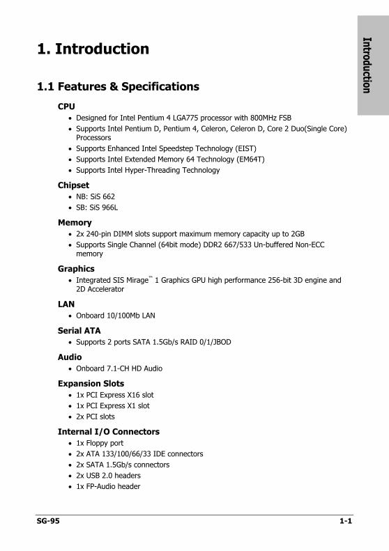
1.1 Features & Specifications
CPU
• Designed for Intel Pentium 4 LGA775 processor with 800MHz FSB
• Supports Intel Pentium D, Pentium 4, Celeron, Celeron D, Core 2 Duo(Single Core) Processors
• Supports Enhanced Intel Speedstep Technology (EIST)
• Supports Intel Extended Memory 64 Technology (EM64T)
• Supports Intel Hyper-Threading Technology
Chipset
• NB: SiS 662
• SB: SiS 966L
Memory
• 2x 240-pin DIMM slots support maximum memory capacity up to 2GB
• Supports Single Channel (64bit mode) DDR2 667/533 Un-buffered Non-ECC memory
Graphics
• Integrated SIS Mirage™ 1 Graphics GPU high performance 256-bit 3D engine and 2D Accelerator
LAN
• Onboard 10/100Mb LAN
Serial ATA
• Supports 2 ports SATA 1.5Gb/s RAID 0/1/JBOD
Audio
• Onboard 7.1-CH HD Audio
Expansion Slots
• 1x PCI Express X16 slot
• 1x PCI Express X1 slot
• 2x PCI slots
Internal I/O Connectors
• 1x Floppy port
• 2x ATA 133/100/66/33 IDE connectors
• 2x SATA 1.5Gb/s connectors
• 2x USB 2.0 headers
• 1x FP-Audio header
SG-95 1-1
• 1x CD-In connector
Rear Panel I/O
• 1x PS/2 Keyboard connector
• 1x PS/2 Mouse connector
• 1x COM port
• 1x Parallel port
• 1x VGA port
• 1x 7.1 HD Audio Connector (Surround-Left / Surround-Right, Rear-Left / Rear-Right, Center / Subwoofer, Mic-In, Line-In, Line-Out)
• 1x RJ-45 LAN port
• 4x USB 2.0 ports
RoHS Compliancy
• 100% Lead-free process and RoHS compliancy
Miscellaneous
• Micro ATX form factor (224mm x 245mm)
※ Specifications and information contained herein are subject to change without notice.
1-2 SG-95
Intro
du
ction
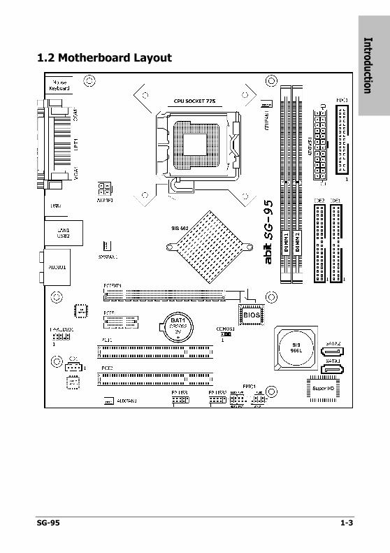
1.2 Motherboard Layout
SG-95 1-3

1-4 SG-95
Hard
ware S
etup
SG-95 2-1
2. Hardware Setup
In this chapter we will elaborate all the information you need upon installing this motherboard to your computer system.
※ Always power off the computer and unplug the AC power cord before adding or removing any peripheral or component. Failing to so may cause severe damage to your motherboard and/or peripherals. Plug in the AC power cord only after you have carefully checked everything.
2.1 Choosing a Computer Chassis
• This motherboard carries a Micro ATX form factor of 224 x 245 mm. Choose a chassis big enough to install this motherboard.
• As some features for this motherboard are implemented by cabling connectors on the motherboard to indicators and switches or buttons on the chassis, make sure your chassis supports all the features required.
• If there is possibility of adopting some more hard drives, make sure your chassis has sufficient power and space for them.
• Most chassis have alternatives for I/O shield located at the rear panel. Make sure the I/O shield of the chassis matches the I/O port configuration of this motherboard. You can find an I/O shield specifically designed for this motherboard in its package.
2.2 Installing Motherboard
Most computer chassis have a base with many mounting holes to allow the motherboard to be securely attached, and at the same time, protected the system from short circuits. There are two ways to attach the motherboard to the chassis base:
1. with studs, 2. or with spacers
In principle, the best way to attach the board is with studs. Only if you are unable to do this should you attach the board with spacers. Line up the holes on the board with the mounting holes on the chassis. If the holes line up and there are screw holes, you can attach the board with studs. If the holes line up and there are only slots, you can only attach with spacers. Take the tip of the spacers and insert them into the slots. After doing this to all the slots, you can slide the board into position aligned with slots. After the board has been positioned, check to make sure everything is OK before putting the chassis back on.
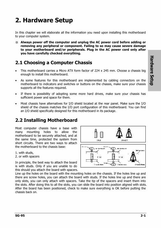
To install this motherboard:
1. Locate all the screw holes onthe motherboard and the chassis base.
2. Place all the studs or spacersneeded on the chassis baseand have them tightened.
3. Face the motherboard’s I/O ports toward the chassis’s rearpanel.
4. Line up all the motherboard’sscrew holes with those studs orspacers on the chassis.
5. Install the motherboard withscrews and have themtightened.
Fa
ce
th
e c
ha
ssis
’s r
ea
r p
an
el.
※ To prevent shorting the PCB circuit, please REMOVE the metal studs or spacers if they are already fastened on the chassis base and are without mounting-holes on the motherboard to align with.
2.3 Checking Jumper Settings
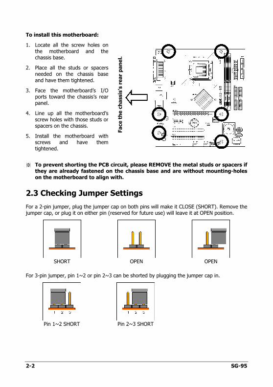
For a 2-pin jumper, plug the jumper cap on both pins will make it CLOSE (SHORT). Remove the jumper cap, or plug it on either pin (reserved for future use) will leave it at OPEN position.
SHORT OPEN OPEN
For 3-pin jumper, pin 1~2 or pin 2~3 can be shorted by plugging the jumper cap in.
Pin 1~2 SHORT Pin 2~3 SHORT
2-2 SG-95

Hard
ware S
etup
SG-95 2-3
2.3.1 CMOS Memory Clearing Header and Backup Battery
The time to clear the CMOS memory occurs when (a) the CMOS data becomes corrupted, (b) you forgot the supervisor or user password preset in the BIOS menu, (c) you are unable to boot-up the system because the CPU ratio/clock was incorrectly set in the BIOS menu, or (d) whenever there is modification on the CPU or memory modules.
This header uses a jumper cap to clear the CMOS memory and have it reconfigured to the default values stored in BIOS.
• Pins 2 and 3 shorted (default): Normal operation.
• Pins 1 and 2 shorted: Clear CMOS memory.
To clear the CMOS memory and load in the default values:
1. Power off the system and disconnect with AC power source.
2. Set pin 1 and pin 2 shorted by the jumper cap. Wait for a few seconds. Set the jumper cap back to its default settings --- pin 2 and pin 3 shorted.
3. Power on the system.
4. For incorrect CPU ratio/clock settings in the BIOS, press <Del> key to enter the BIOS setup menu right after powering on system.
5. Set the CPU operating speed back to its default or an appropriate value.
6. Save and exit the BIOS setup menu.
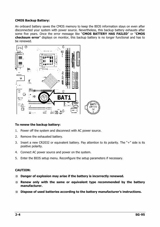
CMOS Backup Battery:
An onboard battery saves the CMOS memory to keep the BIOS information stays on even after disconnected your system with power source. Nevertheless, this backup battery exhausts after some five years. Once the error message like “CMOS BATTERY HAS FAILED” or “CMOS checksum error” displays on monitor, this backup battery is no longer functional and has to be renewed.
To renew the backup battery:
1. Power off the system and disconnect with AC power source.
2. Remove the exhausted battery.
3. Insert a new CR2032 or equivalent battery. Pay attention to its polarity. The “+” side is its positive polarity.
4. Connect AC power source and power on the system.
5. Enter the BIOS setup menu. Reconfigure the setup parameters if necessary.
CAUTION:
※ Danger of explosion may arise if the battery is incorrectly renewed.
※ Renew only with the same or equivalent type recommended by the battery manufacturer.
※ Dispose of used batteries according to the battery manufacturer’s instructions.
2-4 SG-95
Hard
ware S
etup
SG-95 2-5
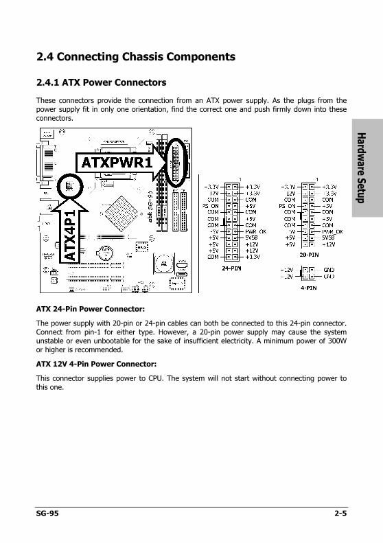
2.4 Connecting Chassis Components
2.4.1 ATX Power Connectors
These connectors provide the connection from an ATX power supply. As the plugs from the power supply fit in only one orientation, find the correct one and push firmly down into these connectors.
ATX 24-Pin Power Connector:
The power supply with 20-pin or 24-pin cables can both be connected to this 24-pin connector. Connect from pin-1 for either type. However, a 20-pin power supply may cause the system unstable or even unbootable for the sake of insufficient electricity. A minimum power of 300W or higher is recommended.
ATX 12V 4-Pin Power Connector:
This connector supplies power to CPU. The system will not start without connecting power to this one.
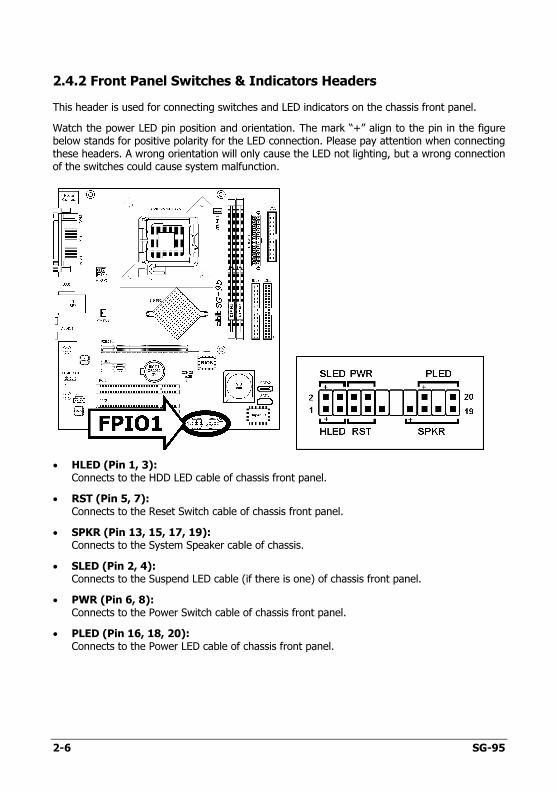
2.4.2 Front Panel Switches & Indicators Headers
This header is used for connecting switches and LED indicators on the chassis front panel.
Watch the power LED pin position and orientation. The mark “+” align to the pin in the figure below stands for positive polarity for the LED connection. Please pay attention when connecting these headers. A wrong orientation will only cause the LED not lighting, but a wrong connection of the switches could cause system malfunction.
• HLED (Pin 1, 3): Connects to the HDD LED cable of chassis front panel.
• RST (Pin 5, 7): Connects to the Reset Switch cable of chassis front panel.
• SPKR (Pin 13, 15, 17, 19): Connects to the System Speaker cable of chassis.
• SLED (Pin 2, 4): Connects to the Suspend LED cable (if there is one) of chassis front panel.
• PWR (Pin 6, 8): Connects to the Power Switch cable of chassis front panel.
• PLED (Pin 16, 18, 20): Connects to the Power LED cable of chassis front panel.
2-6 SG-95
Hard
ware S
etup
SG-95 2-7
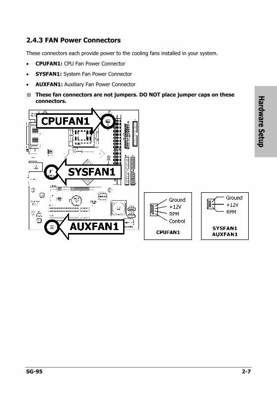
2.4.3 FAN Power Connectors
These connectors each provide power to the cooling fans installed in your system.
• CPUFAN1: CPU Fan Power Connector
• SYSFAN1: System Fan Power Connector
• AUXFAN1: Auxiliary Fan Power Connector
※ These fan connectors are not jumpers. DO NOT place jumper caps on these connectors.
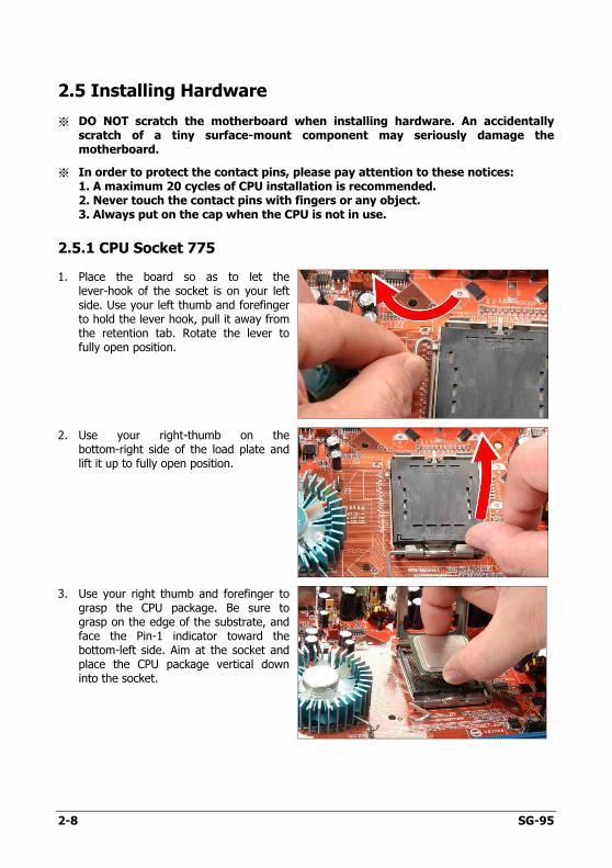
2.5 Installing Hardware
※ DO NOT scratch the motherboard when installing hardware. An accidentally scratch of a tiny surface-mount component may seriously damage the motherboard.
※ In order to protect the contact pins, please pay attention to these notices: 1. A maximum 20 cycles of CPU installation is recommended. 2. Never touch the contact pins with fingers or any object. 3. Always put on the cap when the CPU is not in use.
2.5.1 CPU Socket 775
1. Place the board so as to let the lever-hook of the socket is on your left side. Use your left thumb and forefinger to hold the lever hook, pull it away from the retention tab. Rotate the lever to fully open position.
2. Use your right-thumb on the bottom-right side of the load plate and lift it up to fully open position.
3. Use your right thumb and forefinger to grasp the CPU package. Be sure to grasp on the edge of the substrate, and face the Pin-1 indicator toward the bottom-left side. Aim at the socket and place the CPU package vertical down into the socket.
2-8 SG-95
Hard
ware S
etup
SG-95 2-9
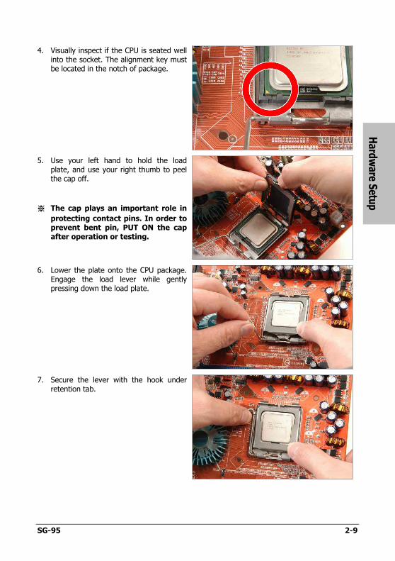
4. Visually inspect if the CPU is seated well into the socket. The alignment key must be located in the notch of package.
5. Use your left hand to hold the load plate, and use your right thumb to peel the cap off.
※ The cap plays an important role in
protecting contact pins. In order to prevent bent pin, PUT ON the cap after operation or testing.
6. Lower the plate onto the CPU package. Engage the load lever while gently pressing down the load plate.
7. Secure the lever with the hook under retention tab.
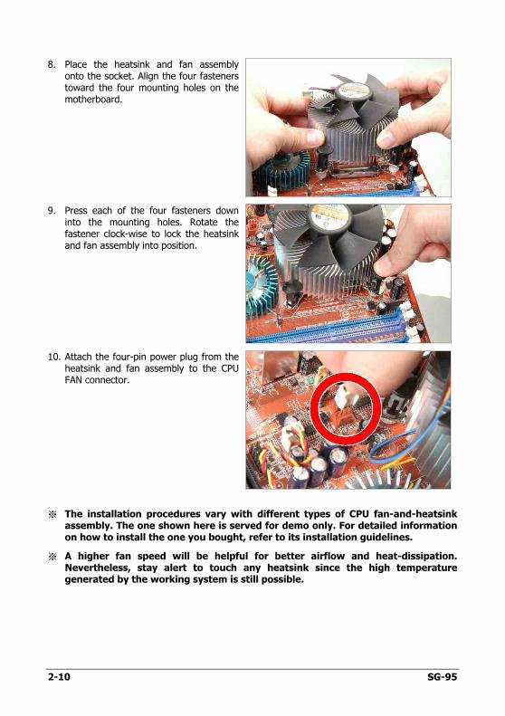
8. Place the heatsink and fan assembly onto the socket. Align the four fasteners toward the four mounting holes on the motherboard.
9. Press each of the four fasteners down into the mounting holes. Rotate the fastener clock-wise to lock the heatsink and fan assembly into position.
10. Attach the four-pin power plug from the heatsink and fan assembly to the CPU FAN connector.
※ The installation procedures vary with different types of CPU fan-and-heatsink assembly. The one shown here is served for demo only. For detailed information on how to install the one you bought, refer to its installation guidelines.
※ A higher fan speed will be helpful for better airflow and heat-dissipation. Nevertheless, stay alert to touch any heatsink since the high temperature generated by the working system is still possible.
2-10 SG-95
Hard
ware S
etup
SG-95 2-11
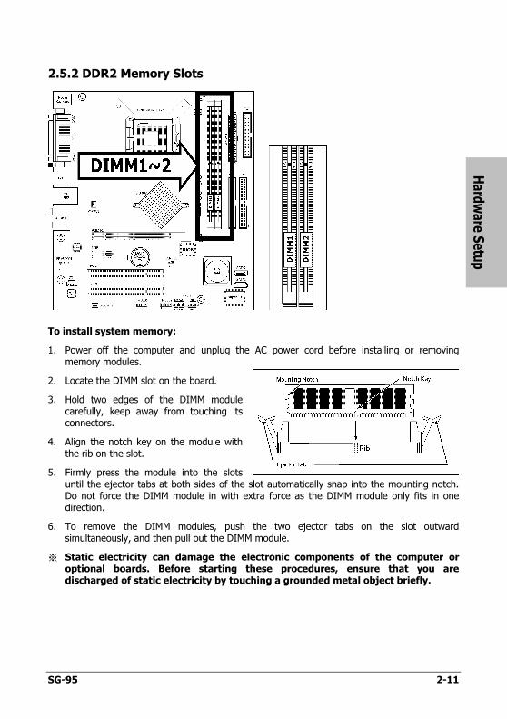
2.5.2 DDR2 Memory Slots
To install system memory:
1. Power off the computer and unplug the AC power cord before installing or removing memory modules.
2. Locate the DIMM slot on the board.
3. Hold two edges of the DIMM module carefully, keep away from touching its connectors.
4. Align the notch key on the module with the rib on the slot.
5. Firmly press the module into the slots until the ejector tabs at both sides of the slot automatically snap into the mounting notch. Do not force the DIMM module in with extra force as the DIMM module only fits in one direction.
6. To remove the DIMM modules, push the two ejector tabs on the slot outward simultaneously, and then pull out the DIMM module.
※ Static electricity can damage the electronic components of the computer or optional boards. Before starting these procedures, ensure that you are discharged of static electricity by touching a grounded metal object briefly.
2.6 Connecting Peripheral Devices
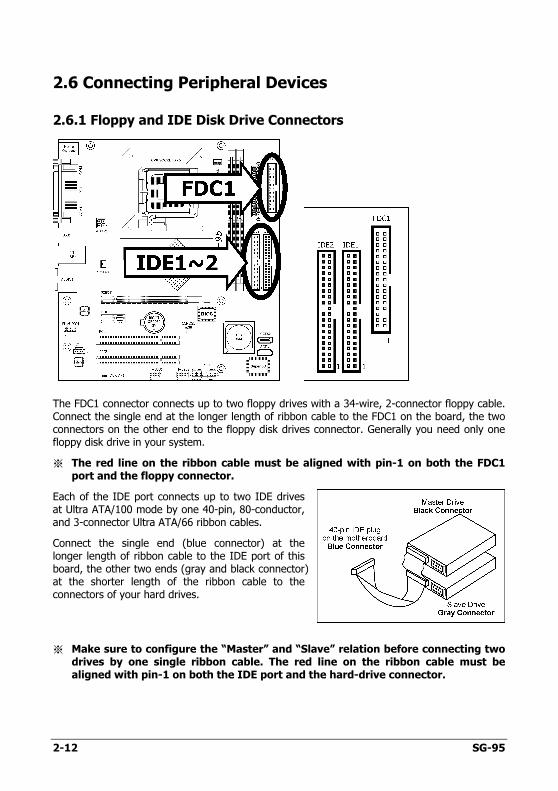
2.6.1 Floppy and IDE Disk Drive Connectors
The FDC1 connector connects up to two floppy drives with a 34-wire, 2-connector floppy cable. Connect the single end at the longer length of ribbon cable to the FDC1 on the board, the two connectors on the other end to the floppy disk drives connector. Generally you need only one floppy disk drive in your system.
※ The red line on the ribbon cable must be aligned with pin-1 on both the FDC1 port and the floppy connector.
Each of the IDE port connects up to two IDE drives at Ultra ATA/100 mode by one 40-pin, 80-conductor, and 3-connector Ultra ATA/66 ribbon cables.
Connect the single end (blue connector) at the longer length of ribbon cable to the IDE port of this board, the other two ends (gray and black connector) at the shorter length of the ribbon cable to the connectors of your hard drives.
※ Make sure to configure the “Master” and “Slave” relation before connecting two drives by one single ribbon cable. The red line on the ribbon cable must be aligned with pin-1 on both the IDE port and the hard-drive connector.
2-12 SG-95
Hard
ware S
etup
SG-95 2-13
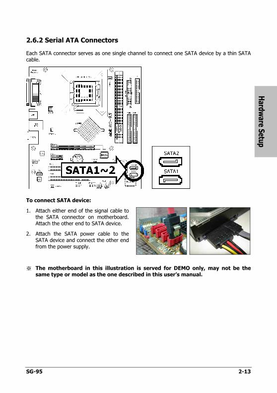
2.6.2 Serial ATA Connectors
Each SATA connector serves as one single channel to connect one SATA device by a thin SATA cable.
To connect SATA device:
1. Attach either end of the signal cable tothe SATA connector on motherboard.Attach the other end to SATA device.
2. Attach the SATA power cable to theSATA device and connect the other endfrom the power supply.
※ The motherboard in this illustration is served for DEMO only, may not be the same type or model as the one described in this user’s manual.
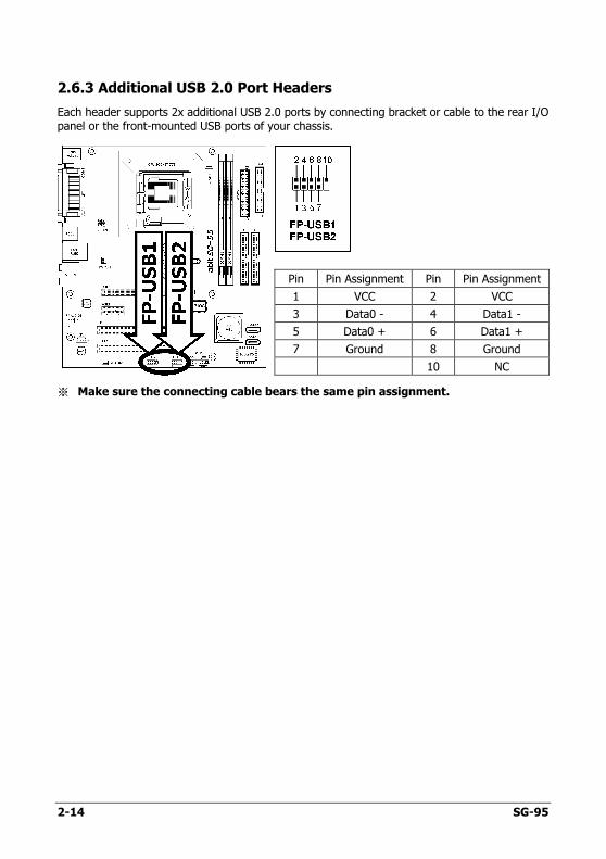
2.6.3 Additional USB 2.0 Port Headers
Each header supports 2x additional USB 2.0 ports by connecting bracket or cable to the rear I/O panel or the front-mounted USB ports of your chassis.
Pin Pin Assignment Pin Pin Assignment
1 VCC 2 VCC
3 Data0 - 4 Data1 -
5 Data0 + 6 Data1 +
7 Ground 8 Ground
10 NC
※ Make sure the connecting cable bears the same pin assignment.
2-14 SG-95
Hard
ware S
etup
SG-95 2-15
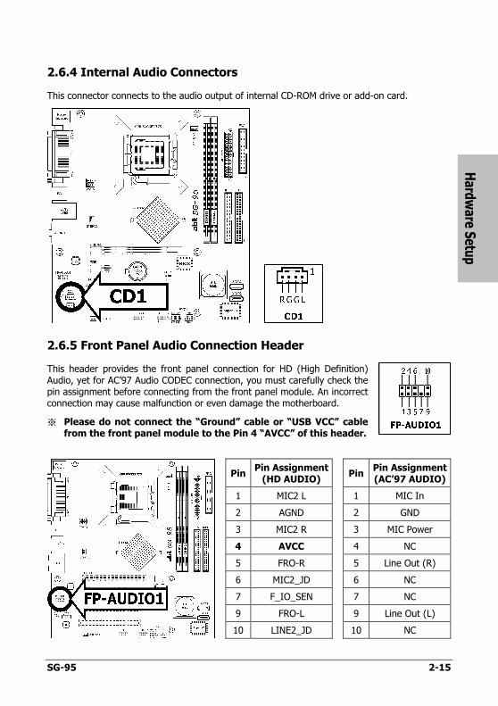
2.6.4 Internal Audio Connectors
This connector connects to the audio output of internal CD-ROM drive or add-on card.
2.6.5 Front Panel Audio Connection Header
This header provides the front panel connection for HD (High Definition) Audio, yet for AC’97 Audio CODEC connection, you must carefully check the pin assignment before connecting from the front panel module. An incorrect connection may cause malfunction or even damage the motherboard.
※ Please do not connect the “Ground” cable or “USB VCC” cable from the front panel module to the Pin 4 “AVCC” of this header.
PinPin Assignment
(HD AUDIO) Pin
Pin Assignment (AC’97 AUDIO)
1 MIC2 L 1 MIC In
2 AGND 2 GND
3 MIC2 R 3 MIC Power
4 AVCC 4 NC
5 FRO-R 5 Line Out (R)
6 MIC2_JD 6 NC
7 F_IO_SEN 7 NC
9 FRO-L 9 Line Out (L)
10 LINE2_JD 10 NC
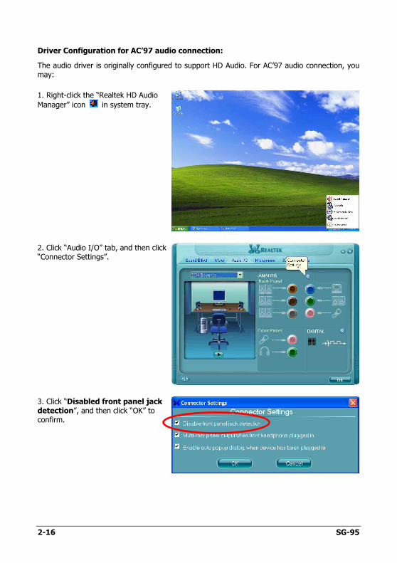
Driver Configuration for AC’97 audio connection:
The audio driver is originally configured to support HD Audio. For AC’97 audio connection, you may:
1. Right-click the “Realtek HD Audio
Manager” icon in system tray.
2. Click “Audio I/O” tab, and then click “Connector Settings”.
3. Click “Disabled front panel jack detection”, and then click “OK” to confirm.
2-16 SG-95
Hard
ware S
etup
SG-95 2-17
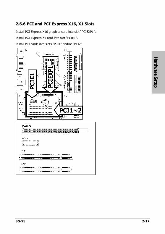
2.6.6 PCI and PCI Express X16, X1 Slots
Install PCI Express X16 graphics card into slot “PCIEXP1”.
Install PCI Express X1 card into slot “PCIE1”.
Install PCI cards into slots “PCI1” and/or “PCI2”.
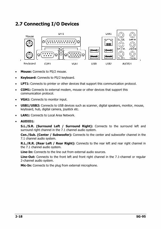
2.7 Connecting I/O Devices
• Mouse: Connects to PS/2 mouse.
• Keyboard: Connects to PS/2 keyboard.
• LPT1: Connects to printer or other devices that support this communication protocol.
• COM1: Connects to external modem, mouse or other devices that support this communication protocol.
• VGA1: Connects to monitor input.
• USB1/USB2: Connects to USB devices such as scanner, digital speakers, monitor, mouse, keyboard, hub, digital camera, joystick etc.
• LAN1: Connects to Local Area Network.
• AUDIO1:
S.L./S.R. (Surround Left / Surround Right): Connects to the surround left and surround right channel in the 7.1 channel audio system.
Cen./Sub. (Center / Subwoofer): Connects to the center and subwoofer channel in the 7.1 channel audio system.
R.L./R.R. (Rear Left / Rear Right): Connects to the rear left and rear right channel in the 7.1 channel audio system.
Line-In: Connects to the line out from external audio sources.
Line-Out: Connects to the front left and front right channel in the 7.1-channel or regular 2-channel audio system.
Mic-In: Connects to the plug from external microphone.
2-18 SG-95
BIO
S S
etup
SG-95 3-1
3. BIOS Setup
This motherboard provides a programmable EEPROM so that you can update the BIOS utility. The BIOS (Basic Input/Output System) is a program that deals with the basic level of communication between processor and peripherals. Use the BIOS Setup program only when installing motherboard, reconfiguring system, or prompted to “Run Setup”. This chapter explains the Setup Utility of BIOS utility.
After powering up the system, the BIOS message appears on the screen, the memory count begins, and then the following message appears on the screen:
PRESS DEL TO ENTER SETUP
If this message disappears before you respond, restart the system by pressing <Ctrl> + <Alt> + <Del> keys, or by pressing the Reset button on computer chassis. Only when these two methods fair should you restart the system by powering it off and then back on.
After pressing <Del> key, the main menu screen appears.
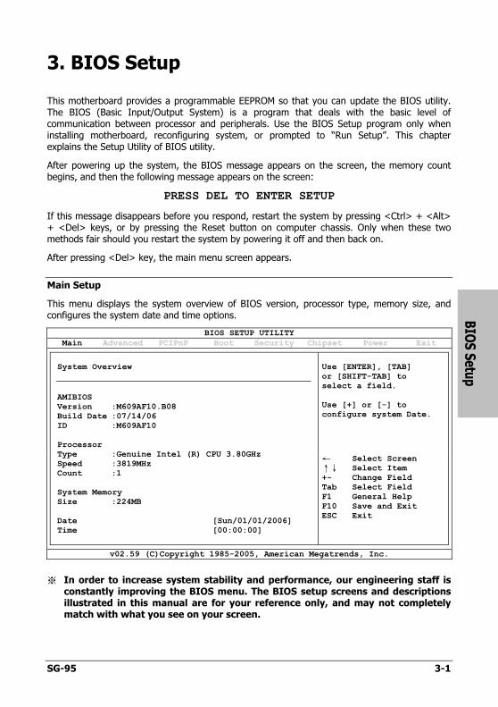
Main Setup
This menu displays the system overview of BIOS version, processor type, memory size, and configures the system date and time options.
BIOS SETUP UTILITY
Main Advanced PCIPnP Boot Security Chipset Power Exit
Use [ENTER], [TAB] or [SHIFT-TAB] to select a field. Use [+] or [-] to configure system Date.
System Overview
AMIBIOS Version :M609AF10.B08 Build Date :07/14/06 ID :M609AF10 Processor Type :Genuine Intel (R) CPU 3.80GHz Speed :3819MHz Count :1 System Memory Size :224MB Date [Sun/01/01/2006] Time [00:00:00]
← Select Screen
↑↓ Select Item +- Change Field Tab Select Field F1 General Help F10 Save and Exit ESC Exit
v02.59 (C)Copyright 1985-2005, American Megatrends, Inc.
※ In order to increase system stability and performance, our engineering staff is constantly improving the BIOS menu. The BIOS setup screens and descriptions illustrated in this manual are for your reference only, and may not completely match with what you see on your screen.
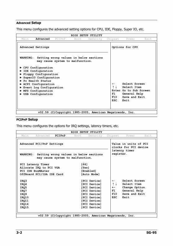
Advanced Setup
This menu configures the advanced setting options for CPU, IDE, Floppy, Super IO, etc.
BIOS SETUP UTILITY
Main Advanced PCIPnP Boot Security Chipset Power Exit
Options for CPU
Advanced Settings
WARNING: Setting wrong values in below sections
may cause system to malfunction. ► CPU Configuration ► IDE Configuration ► Floppy Configuration ► SuperIO Configuration ► Pc Health Status ► ACPI Configuration ► Event Log Configuration ► MPS Configuration ► USB Configuration
← Select Screen
↑↓ Select Item Enter Go to Sub Screen F1 General Help F10 Save and Exit ESC Exit
v02.59 (C)Copyright 1985-2005, American Megatrends, Inc.
PCIPnP Setup
This menu configures the options for IRQ settings, latency timers, etc.
BIOS SETUP UTILITY
Main Advanced PCIPnP Boot Security Chipset Power Exit
Value in units of PCI clocks for PCI device latency timer register.
Advanced PCI/PnP Settings
WARNING: Setting wrong values in below sections
may cause system to malfunction. PCI Latency Timer [64] Allocate IRQ to PCI VGA [Yes] PCI IDE BusMAster [Enabled] OffBoard PCI/ISA IDE Card [Auto Mode] IRQ3 [PCI Device] IRQ4 [PCI Device] IRQ5 [PCI Device] IRQ7 [PCI Device] IRQ9 [PCI Device] IRQ10 [PCI Device] IRQ11 [PCI Device] IRQ14 [PCI Device] IRQ15 [PCI Device]
← Select Screen
↑↓ Select Item +- Change Option F1 General Help F10 Save and Exit ESC Exit
v02.59 (C)Copyright 1985-2005, American Megatrends, Inc.
3-2 SG-95
BIO
S S
etup
SG-95 3-3
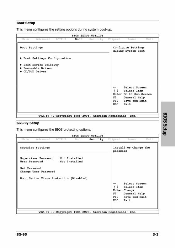
Boot Setup
This menu configures the setting options during system boot-up.
BIOS SETUP UTILITY
Main Advanced PCIPnP Boot Security Chipset Power Exit
Configure Settings during System Boot
Boot Settings
► Boot Settings Configuration ► Boot Device Priority ► Removable Drives ► CD/DVD Drives
← Select Screen
↑↓ Select Item Enter Go to Sub Screen F1 General Help F10 Save and Exit ESC Exit
v02.59 (C)Copyright 1985-2005, American Megatrends, Inc.
Security Setup
This menu configures the BIOS protecting options.
BIOS SETUP UTILITY
Main Advanced PCIPnP Boot Security Chipset Power Exit
Install or Change the password
Security Settings
Supervisor Password :Not Installed User Password :Not Installed Set Password Change User Password Boot Sector Virus Protection [Disabled]
← Select Screen
↑↓ Select Item Enter Change F1 General Help F10 Save and Exit ESC Exit
v02.59 (C)Copyright 1985-2005, American Megatrends, Inc.
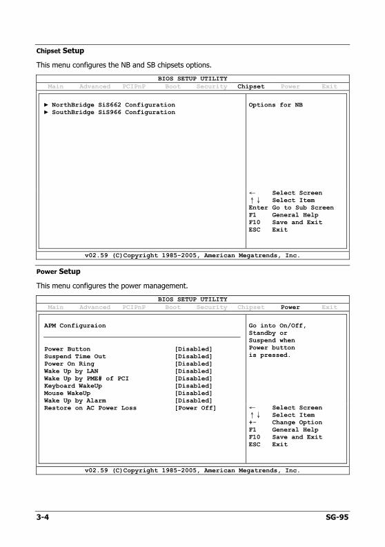
Chipset Setup
This menu configures the NB and SB chipsets options.
BIOS SETUP UTILITY
Main Advanced PCIPnP Boot Security Chipset Power Exit
Options for NB
► NorthBridge SiS662 Configuration ► SouthBridge SiS966 Configuration
← Select Screen
↑↓ Select Item Enter Go to Sub Screen F1 General Help F10 Save and Exit ESC Exit
v02.59 (C)Copyright 1985-2005, American Megatrends, Inc.
Power Setup
This menu configures the power management.
BIOS SETUP UTILITY
Main Advanced PCIPnP Boot Security Chipset Power Exit
Go into On/Off, Standby or Suspend when Power button is pressed.
APM Configuraion
Power Button [Disabled] Suspend Time Out [Disabled] Power On Ring [Disabled] Wake Up by LAN [Disabled] Wake Up by PME# of PCI [Disabled] Keyboard WakeUp [Disabled] Mouse WakeUp [Disabled] Wake Up by Alarm [Disabled] Restore on AC Power Loss [Power Off]
← Select Screen
↑↓ Select Item +- Change Option F1 General Help F10 Save and Exit ESC Exit
v02.59 (C)Copyright 1985-2005, American Megatrends, Inc.
3-4 SG-95
BIO
S S
etup
SG-95 3-5
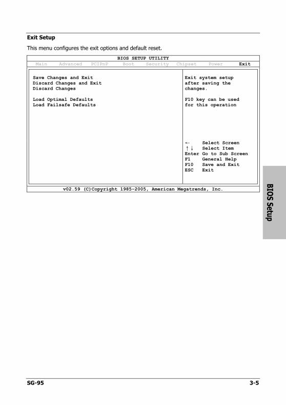
Exit Setup
This menu configures the exit options and default reset.
BIOS SETUP UTILITY
Main Advanced PCIPnP Boot Security Chipset Power Exit
Exit system setup after saving the changes. F10 key can be used for this operation
Save Changes and Exit Discard Changes and Exit Discard Changes Load Optimal Defaults Load Failsafe Defaults
← Select Screen
↑↓ Select Item Enter Go to Sub Screen F1 General Help F10 Save and Exit ESC Exit
v02.59 (C)Copyright 1985-2005, American Megatrends, Inc.

3-6 SG-95
Driver &
Utility C
D
SG-95 4-1
4. Driver & Utility CD
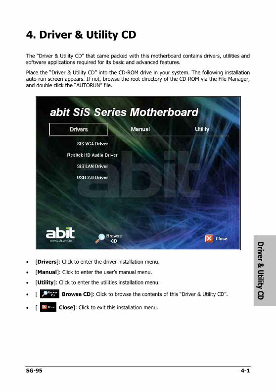
The “Driver & Utility CD” that came packed with this motherboard contains drivers, utilities and software applications required for its basic and advanced features.
Place the “Driver & Utility CD” into the CD-ROM drive in your system. The following installation auto-run screen appears. If not, browse the root directory of the CD-ROM via the File Manager, and double click the “AUTORUN” file.
• [Drivers]: Click to enter the driver installation menu.
• [Manual]: Click to enter the user’s manual menu.
• [Utility]: Click to enter the utilities installation menu.
• [ Browse CD]: Click to browse the contents of this “Driver & Utility CD”.
• [ Close]: Click to exit this installation menu.
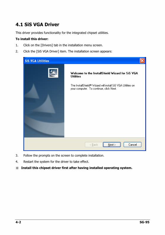
4.1 SiS VGA Driver
This driver provides functionality for the integrated chipset utilities.
To install this driver:
1. Click on the [Drivers] tab in the installation menu screen.
2. Click the [SiS VGA Driver] item. The installation screen appears:
3. Follow the prompts on the screen to complete installation.
4. Restart the system for the driver to take effect.
※ Install this chipset driver first after having installed operating system.
4-2 SG-95
Driver &
Utility C
D
SG-95 4-3
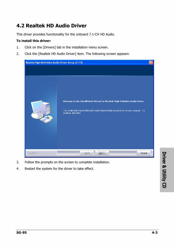
4.2 Realtek HD Audio Driver
This driver provides functionality for the onboard 7.1-CH HD Audio.
To install this driver:
1. Click on the [Drivers] tab in the installation menu screen.
2. Click the [Realtek HD Audio Driver] item. The following screen appears:
3. Follow the prompts on the screen to complete installation.
4. Restart the system for the driver to take effect.
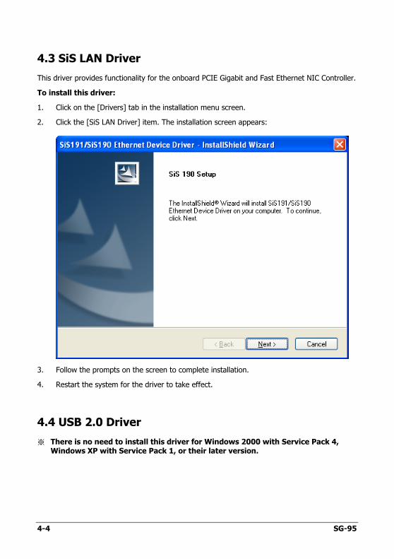
4.3 SiS LAN Driver
This driver provides functionality for the onboard PCIE Gigabit and Fast Ethernet NIC Controller.
To install this driver:
1. Click on the [Drivers] tab in the installation menu screen.
2. Click the [SiS LAN Driver] item. The installation screen appears:
3. Follow the prompts on the screen to complete installation.
4. Restart the system for the driver to take effect.
4.4 USB 2.0 Driver
※ There is no need to install this driver for Windows 2000 with Service Pack 4, Windows XP with Service Pack 1, or their later version.
4-4 SG-95
Driver &
Utility C
D
SG-95 4-5
4.5 SiS Raid Driver Disk
This procedure is necessary if you want to install operating system to a RAID configuration connected among “SATA1~SATA2” connectors:
1. Prepare a 3.5” floppy disk drive and connect it to “FDC1” connector on this motherboard.
2. Start install operating system.
3. Insert this driver disk into floppy disk drive when the screen instruction prompts you to install a third-party SCSI or RAID driver.
4. Press <F6> key, and then follow the screen instruction to complete the installation.
To create a driver disk:
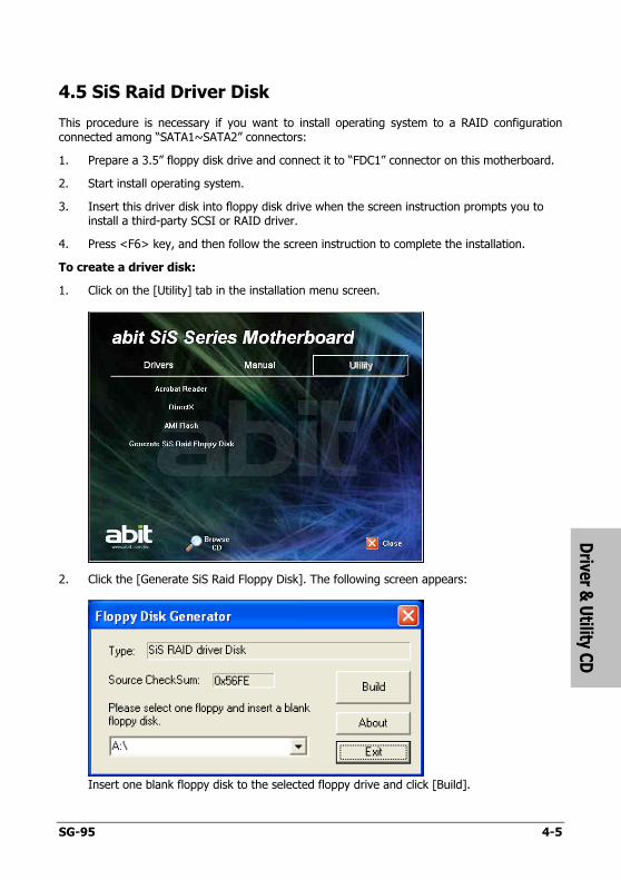
1. Click on the [Utility] tab in the installation menu screen.
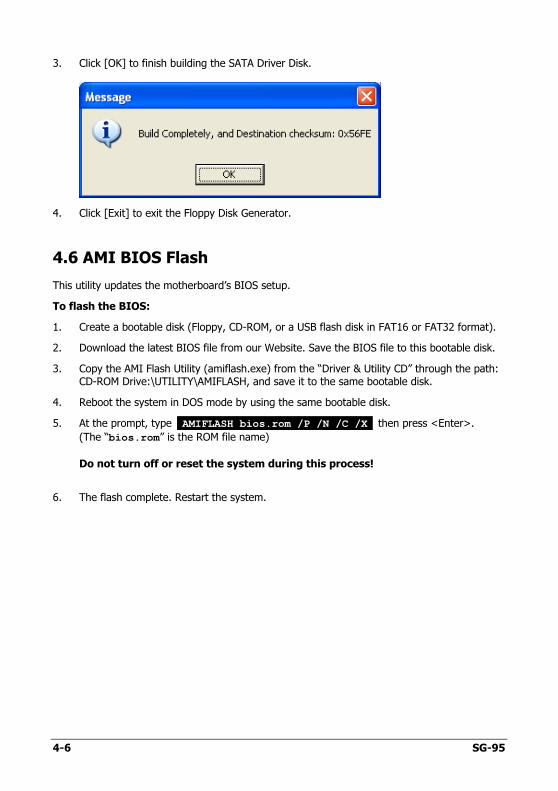
2. Click the [Generate SiS Raid Floppy Disk]. The following screen appears:
Insert one blank floppy disk to the selected floppy drive and click [Build].
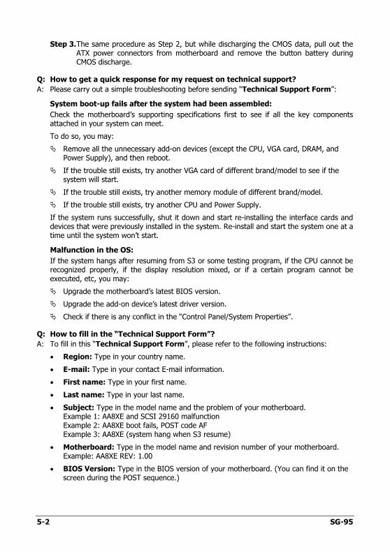
3. Click [OK] to finish building the SATA Driver Disk.
4. Click [Exit] to exit the Floppy Disk Generator.
4.6 AMI BIOS Flash
This utility updates the motherboard’s BIOS setup.
To flash the BIOS:
1. Create a bootable disk (Floppy, CD-ROM, or a USB flash disk in FAT16 or FAT32 format).
2. Download the latest BIOS file from our Website. Save the BIOS file to this bootable disk.
3. Copy the AMI Flash Utility (amiflash.exe) from the “Driver & Utility CD” through the path: CD-ROM Drive:\UTILITY\AMIFLASH, and save it to the same bootable disk.
4. Reboot the system in DOS mode by using the same bootable disk.
5. At the prompt, type AMIFLASH bios.rom /P /N /C /X then press <Enter>.
(The “bios.rom” is the ROM file name)
Do not turn off or reset the system during this process!
6. The flash complete. Restart the system.
4-6 SG-95

Ap
pen
dix
SG-95 5-1
5. Appendix
5.1 Troubleshooting (How to Get Technical Support?) 5.1.1 Q & A
Q: Do I need to clear the CMOS before I use a new motherboard to assemble my new computer system?
A: Yes, we highly recommend that you clear the CMOS before installing a new motherboard. Please move the CMOS jumper from its default 2-3 position to 1-2 for a few seconds, and then back. When you boot up your system for the first time, follow the instructions in the user's manual to load the optimized defaults.
Q: If my system hangs when I update the BIOS or set the wrong CPU parameters, what should I do?
A: Whenever you update the BIOS or if the system hangs due to wrong CPU parameters setting, always clear CMOS jumper before booting up again.
Q: Why does the system fail to boot up again right after a mechanical power-off?
A: Please keep a 30-second interval between each mechanical power On/Off.
Q: Why does the system fail to boot up and nothing displays on the screen after I did some over-clocking or non-standard settings inside the BIOS?
A: It should not cause hardware or permanent damage to motherboard when BIOS settings were changed from default to over-clocking or non-standard status.
We suggest the following three troubleshooting methods to discharge CMOS data, recover the hardware default status, and then making the motherboard work again. There is no need to bother returning the motherboard to where you bought it from or go through an RMA process.
Step 1. Switch off the power supply unit and then switch it on again after one minute. If there is no power-switch on the power supply unit, disconnect its power cord for one minute and then reconnect.
Press and hold the <Insert> key on the keyboard, and press the power-on button to boot up system. If it works, release the <Insert> key and hit <Del> key to enter the BIOS setup page to apply the correct settings.
If the situation remains the same, repeat the procedures in Step 1 for three times, or try Step 2.
Step 2. Switch off the power supply unit or disconnect the power cord. Open the chassis cover. Locate the CCMOS jumper near the button battery. Change the jumper position from default 2-3 to 1-2 for one minute to discharge the CMOS data, and then put it back to default 2-3 position.
Close the chassis and switch on the power supply unit or plug in the power cord. Press the power-on button to boot up system. If it works, hit <Del> key to enter the BIOS setup page to do the correct settings.
If the situation remains the same, try Step 3.
Step 3. The same procedure as Step 2, but while discharging the CMOS data, pull out the ATX power connectors from motherboard and remove the button battery during CMOS discharge.
Q: How to get a quick response for my request on technical support?
A: Please carry out a simple troubleshooting before sending “Technical Support Form”:
System boot-up fails after the system had been assembled:
Check the motherboard’s supporting specifications first to see if all the key components attached in your system can meet.
To do so, you may:
� Remove all the unnecessary add-on devices (except the CPU, VGA card, DRAM, and Power Supply), and then reboot.
� If the trouble still exists, try another VGA card of different brand/model to see if the system will start.
� If the trouble still exists, try another memory module of different brand/model.
� If the trouble still exists, try another CPU and Power Supply.
If the system runs successfully, shut it down and start re-installing the interface cards and devices that were previously installed in the system. Re-install and start the system one at a time until the system won’t start.
Malfunction in the OS:
If the system hangs after resuming from S3 or some testing program, if the CPU cannot be recognized properly, if the display resolution mixed, or if a certain program cannot be executed, etc, you may:
� Upgrade the motherboard’s latest BIOS version.
� Upgrade the add-on device’s latest driver version.
� Check if there is any conflict in the “Control Panel/System Properties”.
Q: How to fill in the “Technical Support Form”?
A: To fill in this “Technical Support Form”, please refer to the following instructions:
• Region: Type in your country name.
• E-mail: Type in your contact E-mail information.
• First name: Type in your first name.
• Last name: Type in your last name.
• Subject: Type in the model name and the problem of your motherboard. Example 1: AA8XE and SCSI 29160 malfunction Example 2: AA8XE boot fails, POST code AF Example 3: AA8XE (system hang when S3 resume)
• Motherboard: Type in the model name and revision number of your motherboard. Example: AA8XE REV: 1.00
• BIOS Version: Type in the BIOS version of your motherboard. (You can find it on the screen during the POST sequence.)
5-2 SG-95
Ap
pen
dix
SG-95 5-3
• CPU: Type in the brand name and the speed (MHz) of your CPU. (Illustrate the over-clocking status if you had done so.) Example: Intel 650 3.4GHz (OC FSB=220MHz)
• Memory brand: Type in the brand and model name of your memory module. Example: Memory brand: Kingston (KVR533D2N4/1G)
• Memory size: Type in the size of your memory module. Example: 512M* 4PCS
• Memory configuration: Type in the memory configuration in BIOS setting. Example: Memory Timing: 2.5-3-3-7 @533MHz
• Graphics information: Note Graphics card’s brand, model and driver version
• Graphics card: Type in the brand and model name of your graphics card. Example: ATI RADEON X850 XT PE
• Graphics driver version: Type in the driver version of your graphics card Example: Catalyst 5.12V
• Power supply maker: Type in the brand and model name of your power supply unit.
• Power supply wattage: Type in the power wattage of your power supply unit.
• Storage devices: Type in the brand and specifications of your HDD drive and quantity. Specify if it was inserted on IDE (Master or Slave) or SATA ports, including the RAID allocation status. Example 1: WD Caviar WD600 60GB (on IDE2 master), Maxtor DiamondMax 10 SATA 300GB (on SATA 3) Example 2: Maxtor DiamondMax 10 SATA 300GB *2 (on SATA 3, SATA 4 RAID 1)
• Optical devices: Type in the brand and specifications of your optical drives and quantity. Specify if it was inserted on IDE (Master or Slave) or SATA ports.
• Other devices: Indicate which add-on cards or USB devices that you absolutely sure are related to the problem. If you cannot identify the problem’s origin, indicate all the add-on cards or USB devices inserted on your system. Example: AHA 29160 (on PCI 2), Sandisk Cruzer mini 256MB USB Flash-disk.
• Operating system: Indicate which OS and language version Example: Microsoft Windows XP SP2, English version Example: Microsoft Media Center Edition 2005, Korean version
• Problem description: Describe the problem of your system configuration. Indicate the steps to duplicate problem if possible. See the next page for a blank Technical Support Form, or visit our website to fill in the form on line (http://www.abit.com.tw/page/en/contact/technical.php).
Q. Is the motherboard dead? Do I need to return it to where I bought from or go through an RMA process?
A: After you had gone through the troubleshooting procedures, yet the problem still exists, or you find an evident damage on the motherboard. Please contact our RMA center. (http://www2.abit.com.tw/page/en/contact/index.php?pFUN_KEY=18000&pTITLE_IMG)
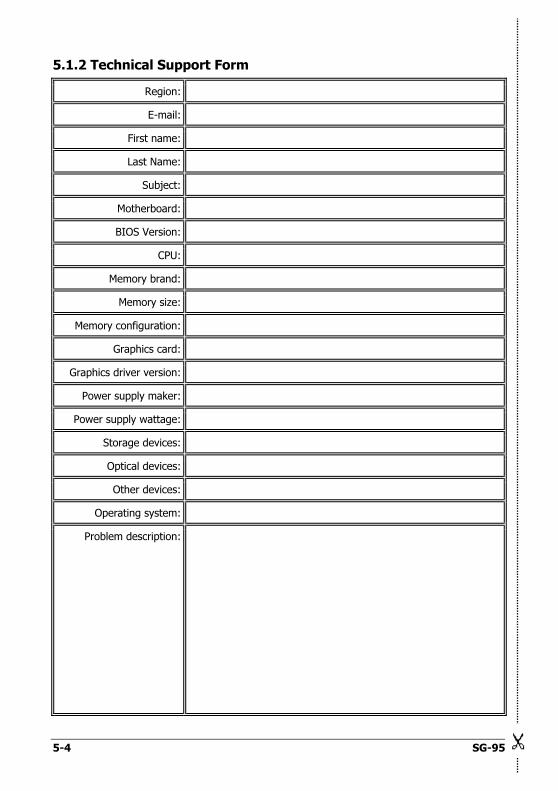
5.1.2 Technical Support Form
5-4 SG-95
Region:
E-mail:
First name:
Last Name:
Subject:
Motherboard:
BIOS Version:
CPU:
Memory brand:
Memory size:
Memory configuration:
Graphics card:
Graphics driver version:
Power supply maker:
Power supply wattage:
Storage devices:
Optical devices:
Other devices:
Operating system:
Problem description:
Ap
pen
dix
SG-95 5-5
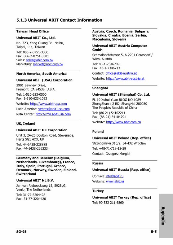
5.1.3 Universal ABIT Contact Information
Taiwan Head Office
Universal ABIT Co., Ltd.
No. 323, Yang Guang St., Neihu, Taipei, 114, Taiwan
Tel: 886-2-8751-3380 Fax: 886-2-8751-3381 Sales: [email protected] Marketing: [email protected]
North America, South America
Universal ABIT (USA) Corporation
2901 Bayview Drive, Fremont, CA 94538, U.S.A.
Tel: 1-510-623-0500 Fax: 1-510-623-1092
Website: http://www.abit-usa.com
Latin America: [email protected]
RMA Center: http://rma.abit-usa.com
UK, Ireland
Universal ABIT UK Corporation
Unit 3, 24-26 Boulton Road, Stevenage, Herts SG1 4QX, UK
Tel: 44-1438-228888 Fax: 44-1438-226333
Germany and Benelux (Belgium, Netherlands, Luxembourg), France, Italy, Spain, Portugal, Greece, Denmark, Norway, Sweden, Finland, Switzerland
Universal ABIT NL B.V.
Jan van Riebeeckweg 15, 5928LG, Venlo, The Netherlands
Tel: 31-77-3204428 Fax: 31-77-3204420
Austria, Czech, Romania, Bulgaria, Slovakia, Croatia, Bosnia, Serbia, Macedonia, Slovenia
Universal ABIT Austria Computer GmbH
Schmalbachstrasse 5, A-2201 Gerasdorf / Wien, Austria
Tel: 43-1-7346709 Fax: 43-1-7346713
Contact: [email protected]
Website: http://www.abit-austria.at
Shanghai
Universal ABIT (Shanghai) Co. Ltd.
FL 19 Xuhui Yuan BLOG NO.1089 ZhongShan s 2 RD, ShangHai 200030 The People's Republic of China
Tel: (86-21) 54102211 Fax: (86-21) 54104791
Website: http://www.abit.com.cn
Poland
Universal ABIT Poland (Rep. office)
Strzegomska 310/2, 54-432 Wroclaw
Tel: +48-71-718-12-39
Contact: Grzegorz Morgiel
Russia
Universal ABIT Russia (Rep. office)
Contact: [email protected]
Website: www.abit.ru
Turkey
Universal ABIT Turkey (Rep. office)
Tel: 90 532 211 6860