introduction - marine museum of the great lakes€¦ · · 2011-12-07second largest canadian...
TRANSCRIPT

1
INTRODUCTION
This fonds consists of the corporate records of Upper Lakes Group Incorporated and its subsidiary
corporations, specifically Upper Lakes Shipping and ULS Marbulk Limited. ULS is currently the
second largest Canadian shipping company operating on the Great Lakes and overseas. The
material is relatively recent dating from 1951 to 1971, and 1988.
As an initial accession it holds potential to be one of among our institution's best collections
documenting the history and growth of a shipping company whose genesis is surprisingly different
from that of other Canadian shipping companies. This difference should prove intrinsic to the fonds
intellectual value due to the linkages it can provide within the broader scope of Canadian business
history - historic linkages with the purchasers and processors of Canada' primary staple commodity,
wheat. ULS moreover, is perhaps best known within the academic (and shipping) communities for
its unique contribution to recent labour history. As one of the largest, and oldest shippers on the
Great Lakes its records should provide a solid counterpoint for comparative analysis with the fonds
of other Great Lakes shipping companies within our archival holdings. This fonds naturally lends
itself to the study of transportation history, marine and technology history, and labour history:
combined its antecedents within the grain trade, it offers potential for a broad overview of Canadian
business history during its most interesting period.
2
ADMINISTRATIVE HISTORY
Unlike other shipping fleets created by maritime men who fostered, raised, and nurtured each ship
like a new arrival to the family, Upper Lakes Shipping began life very much the unplanned child:
and its putative father was the Toronto Elevator Company. The founder, Gordon C. Leitch, had
been trained in the grain forwarding business in Manitoba and Toronto. A man of uncanny business
acumen, he noticed during the nadir of the early Depression, a unique opportunity in Toronto to
service the flour mills located there in a profitable manner. Surprisingly this, the industrial engine of
Ontario, had no grain elevators. Prairie wheat was stored in elevators on Georgian Bay, then hauled
overland on an as need basis. It was slow and expensive. The key to the concept was the newly
expanded Welland canal which would allow larger vessels into the lower lakes: shipping directly
from the Lakehead thereby eliminating the overland leg would substantially reduce the cost of
wheat. Leitch and his backers quickly built a state of the art elevator on the Toronto waterfront.
Situated next door to the city's milling industry they were in the position to service their customers
faster and at a higher profit margin than those who continued to haul from Georgian Bay.
Unfortunately, the Georgain Bay elevator companies had enough commercial leverage to
discourage shipping companies from unloading at the new Toronto Elevator Company. In order to
fill his granary Gordon Leitch was forced to the unwonted expedient of buying his own ship, the
Sarnian, and in 1931 she became the embryo of Upper Lakes Shipping.
One ship however soon proved woefully inadequate to the task. At this juncture a longtime
partnership was forged with the established Chicago grain firm of James Norris. Norris provided
the capital to aggressively purchase more vessels and suddenly this sideline to Leitch's grain
forwarding business began to grow exponentially. Incorporated in 1932 as the Upper Lakes and St.
Lawrence Transportation Company (later shortened to Upper Lakes Shipping), this marked the
formal beginning of the company's history. Incredibly, the unpromising commercial climate of the
mid 1930s' was no impediment to the company's rapid growth. Leitch's original concept of building
an elevator at Toronto provided the engine while James Norris' capital provided the fuel that
generated the accelerated expansion of the ULS fleet. From 1931 to 1940 the company increased
from one to thirty-four vessels - a mix of canallers and larger bulk carriers, the largest being the 472
3
foot Victorious.
From their outgrowth as grain merchants Leitch and Norris had succeeded splendidly in a field
relatively new to them; creating and operating a fleet of ships. However as grain forwarders they
knew better than most the value of elevators for their ability store grain (thereby freeing up ships to
continue freighting), and they knew how to site them strategically. The commercial elevators at the
seaports of Montreal and Quebec were annual bottlenecks for all the competing fleets, consuming
time and profits as they waited to unload outbound wheat. In 1937 Upper Lakes Shipping
sidestepped the issue by building their own facility at the small port of Trois Rivieres. It was a
return to Leitch's original inspiration for building at Toronto; and the company continued the
practice, later purchasing an elevator at Goderich in 1954.
In 1939 Upper Lake Shipping, like most other Canadian merchant fleets made its contribution to
the war effort, sending ten canallers to the Atlantic. The enemy sent six to the bottom.
Upper Lakes Shipping's genesis was actually a commercial decision by Toronto Elevators towards
vertical integration within the grain forwarding business. And although by 1940 the shipping
business had outgrown its commercial forebearer, Gordon Leitch was still a grain merchant bent
upon further vertical growth. Beyond shipping and selling wheat, the next step was to process it.
The Norris Grain firm was already heavily involved in the huge conglomerate Maple Leaf Mills; so
Leitch established a modest agricultural feed mill and called it Master Feeds - a name well known
to farmers throughout Ontario. From the beginning the grain business and the shipping business
together had been integral to the Leitch/Norris partnership in Upper Lakes Shipping.
In the immediate postwar years Upper Lakes began purchasing larger ships and disencumbering
itself of its many 250 foot canallers in anticipation of the new Seaway, which would open in 1959
and allow vessels as long as 750 feet access from the sea to the Lakehead. In 1952 Upper Lakes
commissioned its first two new vessels to be built at Port Weller; they were aptly named the James
Norris and Gordon C. Leitch. Almost coincident with their launching of their namesakes was the
demise of the two founding partners: happily their respective sons - both raised to the business -

4
continued the partnership with the same strategies of horizontal growth (more shipping capacity)
and the vertical integration into complementary industries. In 1956 the company bought Port Weller
Drydocks. Then partially jettisoning the old practice of buying older vessels and refitting, the firm
began constructing new, purpose built vessels designed to meet specific freight and classification
needs. The existing fleet was aging; plus the new competition brought in by the Seaway, and the
decision to move into ocean shipping, were the motivating factors behind the investment in new
construction.
The move towards ocean shipping in the early 1960s was tentative. The Leitch holding company,
Leitch Transport managed the business rather than ULS directly. Cooperative efforts with foreign
shippers and off-shore Caribbean companies were set up as pilot projects. Foreign built ocean class
vessels were first tried, some purchased, some chartered - such as the Red Wing and Elat
respectively. The creation of an ocean going merchant fleet was the next logical step for company
growth; however it was precisely at this delicate moment that Upper Lakes met its most formidable
business nemesis in the form of the redoubtable and reckless leader of the (Canadian) Seafarers
International Union, Mr. Hal Banks. By the early 1960s the SIU completely controlled crewing and
stevedoring on both sides of the Great Lakes, and it harboured a particular resentment against
Upper Lakes Shipping for its reluctance to cheerfully embrace the SIU when it first entered
Canadian waters. Jack Leitch, backed by loyal crews, decided to outmanoeuvre the truculent SIU by
signing his people with a rival, more amenable union. The SIU's animosity exploded into open
warfare in 1961 with broken contracts and broken heads a regular feature of the contest. The ULS
ship Howard L. Shaw was bombed in Chicago harbour. The furore ended with a royal commission
and Hal Bank's indictment for criminal activity in 1967. For his standing toe to toe with the union
bully, Jack Leitch was acclaimed 'Great Lakes Man of the Year' by his peers in the shipping
industry in 1965. The losses incurred during the union war however had disenchanted Leitch's
longtime silent partner Bruce Norris, who wished to divest himself of his interest in Upper Lakes
Shipping. Finally in 1974 the Leitch/Norris partnership was dissolved. In the process Norris gained
full control of the Leitch shares in the milling business - under the umbrella of Maple Leaf Mills -
in return Leitch Transport gained full control of Upper Lakes Shipping. From 1974 on ULS
operated as a shipping and shipbuilding company solely. Its historic and commercial links with its

5
own roots, the grain trade, had ended.
The 1970s was a decade of renewal and expansion. The Great Lakes fleet was rejuvenated with
fewer, but new, larger, and more efficient self-unloading ships. This was a technology forged
largely by Canadians on the Great Lakes: it greatly diminished the cargo turnaround time in
harbour. Time saved in port equalled more trips and more profit. Then in 1972 the large
Papachristidis fleet was purchased, thus making Upper Lakes the second largest Canadian fleet on
the Great Lakes. In 1973 the federal Darling Report required coastal and inland freight moving
between Canadian ports to be carried in Canadian bottoms. This stipulation would stimulate the
growth of a Canadian ocean merchant marine by guaranteeing cargo routes such as carrying coal
from Cape Breton inland. Upper Lakes' seagoing fleet had grown to seven ships by 1975. This
included the company's largest vessel the 74,000 ton Phosphore Conveyor. Ironically, with the
onset of recession in the early 1980s this very fleet was the first to downsize in order to protect the
core of the company's operations on the Great Lakes.
In order to carve a commercial niche in the ultra competitive seagoing trade, company president
Jack Leitch determined to capitalize on the Canadian technology of self-unloading equipment by
servicing small foreign ports whose harbours had little or no cargo handling facilities, and where
the typical ocean bulk carrier was handicapped. ULS Marbulk Incorporated was formally
established to manage the surviving and now rejuvenatated ocean fleet. It was composed of the
seagoing self-unloaders Ambassador, Pioneer, Citadel Hill and the new Panamax self-unloader
Nelvana, along with the bulk carriers Thornhill and Richmond Hill (the latter two added in 1993).
The 1990s are synonymous with retrenchment, downsizing and creative management - just keep a
company afloat (if the reader will indulge the metaphor). In 1990 Upper Lakes Shipping and
erstwhile competitor Algoma Central, coordinated management of their bulk carriers under the
name of 'Seaway Bulk Carriers'. In 1993 Seaway Bulk Carriers acquired fifteen bulkers from
Canada Steamship Lines, Misener Shipping, and Pioneer Shipping. It was a calculated risk: some of
the vessels have proved capable carriers, some not. As of 1995/96 the Upper Lakes Shipping Great
Lakes fleet comprises seven self-unloaders and nine bulk carriers. ULS Marbulk's ocean fleet
consists of four self-unloaders and two bulk carriers. Port Weller Drydock, currently the only viable

6
shipyard on the Canadian lakes is coowned with Canadian Shipbuilding and Engineering.

7
SCOPE AND CONTENT NOTES
Introduction
The Upper Lakes Shipping fonds consists of the records of two branch corporations of Upper Lakes
Group Incorporated: Upper Lakes Shipping, and ULS Marbulk Limited.
Arrangement
The collection at present consists of one accession arranged into two subgroups, the primary
division based upon medium with manuscript material forming the first part and graphic material in
the form of ship plans comprising the second part.
Within the manuscript subgroup three series were defined: Series A Fleet Operations (Great
Lakes); Series B Ocean Shipping; and Series C Engineering. This series organization was largely
determined by the principle of preserving original order and hopefully reflects as accurately as
possible the company's operations. This subgroup totals approximately 12.75 cubic feet of material.
The overall date range being 1951-1971, 1988.
The ship plan subgroup consists of approximately 33 cubic feet of graphic material which translates
into almost 2550 plans by count. These plans are almost exclusively blueprints (folded). Following
ship register convention, the plans are primarily arranged alphabetically, according to vessel name.
At the item level, the individual plans were often numbered by the company. They have remained
in this order, and are listed thus. Where no company number was found the plans were assigned
item level numbers from .1 onwards. Full accession numbers have been assigned at the archivist's
discretion - each box being allotted a main tripartite number, then each item's own number
concatenates to this to form a four element accession number for each plan. (Thus plan .23 in box
1995.26.25 is fully identified as plan 1995.26.25.23).
Provenance
All material was created by Upper Lakes Group Incorporated or its antecedents. The fonds was
donated to the Marine Museum of the Great Lakes at Kingston by Upper Lakes Shipping of

8
Toronto and St. Catharines, Ontario.
Restrictions
All currently received records are open.
Copyright
Copyright to all materials, manuscripts, drawings, and photographs has been transferred in toto to
the Marine Museum of the Great Lakes at Kingston.
Finding Aids
A detailed inventory is available in bound hardcopy. The fonds can also be accessed on the Internet
via Queens University's Stauffer Library system. Once in the Marine Museum's database use the
command 'K=archival Upper Lakes Shipping' to extract the fonds.
9
Series A Fleet Operations
This series represents the activities of one of the four current departments comprising Upper Lakes
Shipping's Great Lakes Operations Division, to wit: Fleet Research and Development;
Engineering; Marketing (Freight); and Fleet Operations. Fleet Operations is responsible for all
aspects of the day to day running of the company fleet, typically: crew personnel; harbour
information and liaison; trip reports or logs, recording the vessels' freight trips and their relative
performance; overseas charter operational files; accident reports; pilotage and canal fees; wharfage
and stevedoring; ship surveys and certifications; and general fleet correspondence. Records created
by executive officers from this department may also be included in the series.
Remark that the deep sea vessels belonging to the ULS shipping group are also managed by a Fleet
Operations department with corresponding duties and similar records. However, the ocean fleet
belongs to a distinct corporate entity, ULS Marbulk Ltd., and is therefore described in a separate
series.
To date, records have been received representing only a portion of this department's responsibilities.
However the records in hand have been determined as belonging to specific subsets or subseries,
which reflect a particular aspect of the department's activities set out above. Respect du fonds was a
principle followed as far as practicable; however since a relatively small sample of this department's
output has been accessioned, some archival interpretation was inevitable. Strictly speaking these are
artificial subseries, exhibiting some degree of imposed order. Two subseries were created: Ports and
Harbours; and Trip Reports. Subseries descriptions precede their respective unit lists within the
corpus of the finding aid.
This series' date range is 1959-71, and 1988. It currently comprises two cubic feet.
10
Series A Fleet Operations
Subseries I Port and Harbours
This subseries is comprised of reference files on ports and harbours to which ULS operated. These
ports are both national and international. The material consists of harbour charts, water lot plans,
related correspondence, drawings of wharves and their cargo loading facilities, and photographs of
the particulars. The units are organized alphabetically by port and the date range is 1959-71. The
material comprises 1 cubic foot.
11
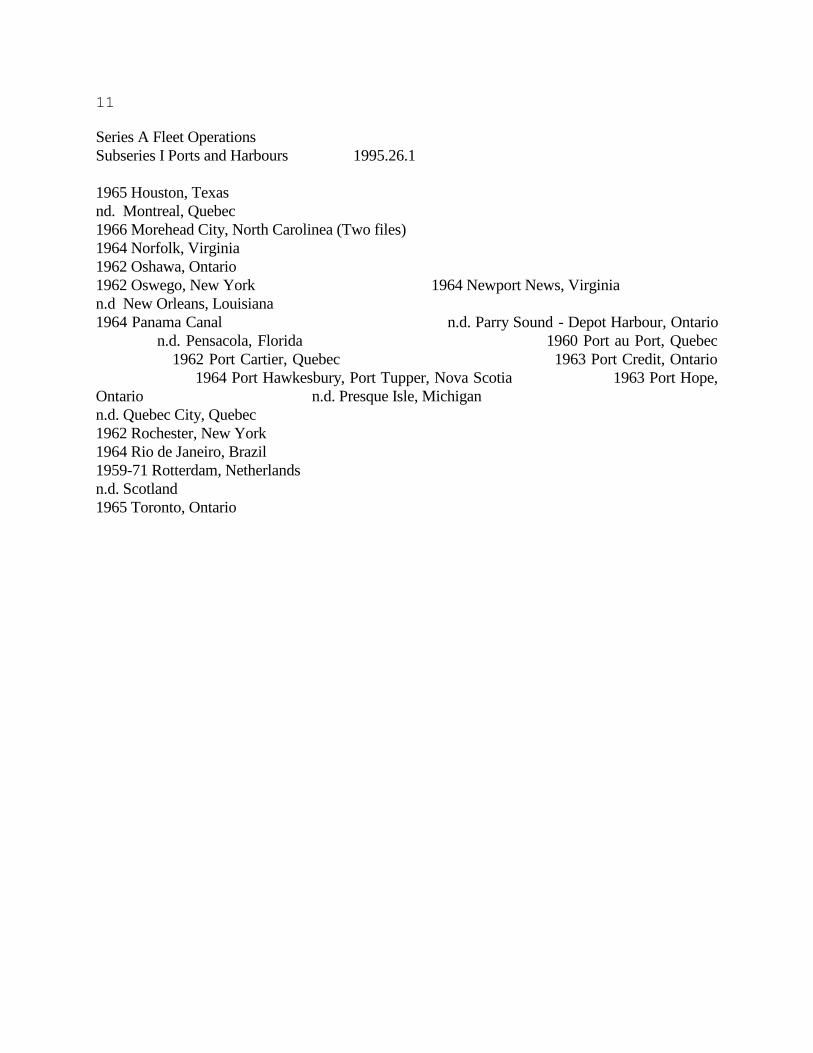
Series A Fleet Operations
Subseries I Ports and Harbours 1995.26.1
1965 Houston, Texas
nd. Montreal, Quebec
1966 Morehead City, North Carolinea (Two files)
1964 Norfolk, Virginia
1962 Oshawa, Ontario
1962 Oswego, New York 1964 Newport News, Virginia
n.d New Orleans, Louisiana
1964 Panama Canal n.d. Parry Sound - Depot Harbour, Ontario
n.d. Pensacola, Florida 1960 Port au Port, Quebec
1962 Port Cartier, Quebec 1963 Port Credit, Ontario
1964 Port Hawkesbury, Port Tupper, Nova Scotia 1963 Port Hope,
Ontario n.d. Presque Isle, Michigan
n.d. Quebec City, Quebec
1962 Rochester, New York
1964 Rio de Janeiro, Brazil
1959-71 Rotterdam, Netherlands
n.d. Scotland
1965 Toronto, Ontario

12
Series A Fleet Operations
Subseries II Trip Reports
This subseries consists of trip reports called Speed Charts, organized according to vessel and the
Seaway sections it passed through enroute. These lists were kept by each master or first mate of a
ULS vessel for each trip - for which the passage of each Seaway section was timed and logged. A
separate speed chart was kept for each seaway section, thus each vessel maintained a series of speed
charts documenting each stage of its route and providing an analysis of its overall performance.
Each file in the subseries contains reports for the whole fleet; the items are organized internally by
ship name and date. All records date to 1988 and comprise one cubic foot of material.

13
Series A Fleet Operations
Subseries II Trip Reports 1995.26.2
[The speed charts for each operating ULS vessel are keyed according to its trip number. Each chart
dated per diem]
1988 Speed Charts April/May
1988 Speed Charts June/July
1988 Speed Charts August/September
1988 Speed Charts October/November
1988 Speed Charts December

14
Series B Ocean Shipping
Upper Lakes Shipping has been engaged in oceangoing shipping since the early 1960s, first on a
tentative basis with ships such as the Wheat King which had an ocean going Lloyd's classification;
then later on a more committed scale with the Inverewe and Elat. Ocean shipping was from the
beginning run as a business entity separate from ULS's Great Lakes fleet: first via the wholly owned
subsidiaries Leitch Transport and Maple Leaf Mills, which first piloted cooperative seagoing efforts
with foreign shippers and then established off-shore ULS subsidiaries such as Gulf Stream Trading
of Bermuda, and Technibulk Shipping of the Bahamas. These ocean going vessels often found
themselves chartered to other shippers when business dictated. There were also some ULS ships in
the Great Lakes fleet which had ocean going classifications - such as the Cape Breton Miner - their
ocean excursions were run directly by ULS. Currently (1996) a separate corporate entity, ULS
Marbulk Limited, manages the ocean going fleet of six ships.
The history of ULS ocean shipping determines the establishment of two subseries which reflects the
operations of the corporation on the high seas: Overseas Charters; and ULS Marbulk Shipping.
Our present accessions belong to the first of these subseries as described below. The series' material
dates to 1966-67 and totals 3 cubic feet.

15
Series B Ocean Shipping
Subseries I Overseas Charters
Leitch Transport, a branch of ULS entered into a seagoing venture with Technibulk Shipping Ltd.
of Nassau, Bahamas in 1966 -the agreement lasting until at least 1969. This small company was
incorporated in Nassau in 1966 with five shareholders and one chartered seagoing ship, the Elat.
(Chartered from Zim Israel Ltd.) Its charter was to operate as a deep sea international shipper; it
came into partnership with Leitch Transport who would manage and operate the vessel on behalf of
Technibulk. Control of a majority of shares was turned over to three officers of Leitch Transport
and it became in effect a subsidiary of ULS: a branch office was opened in Toronto. (Note that this
vessel, unlike Inverewe, was never owned by ULS, and thus does not show up on any fleet list).
This venture had as an antecedent the seagoing operation of the Inverewe (ca 1962-68) which was
also run under the auspices of an Caribbean subsidiary, the Gulf Stream Trading Company. One file
documenting Voyage 2 of Inverewe is included in this subseries as well as one file for the charter
trips of the Phosphate Conveyor: Note that these latter two vessels were owned directly by ULS.
The following files document the establishment of Technibulk Shipping and its agreement with
Leitch Transport. Included are all of the Elat's log abstracts and trip reports for 1967. Of primary
importance is the Elat Itinerary for 1967 which gives a synopsis of its activities for the year. These
activities are fully documented in the subsequent Voyage Files, titled according to voyage number
and departure and destination ports. These files contain: copies of vessel charter from Zim Israel
Ltd.; correspondence, including telexes; bills of lading; manifests; log abstracts; Port Logs and
Statements of Facts; port charges including stevedoring; tug charges; demurrage documents; freight
contract documents; invoices to freight customers; purchase orders and invoices ongoing for repairs
and supplies; pilotage fees; debit and credit notes; canal and custom documents; accident reports
and legal protests; cost account working papers; miscellaneous accounting documents;
miscellaneous plans; and Voyage Result Statements (ie: financial statements for a given trip). The
subseries comprises 3 cubic feet of material all dating to 1966-67.
16
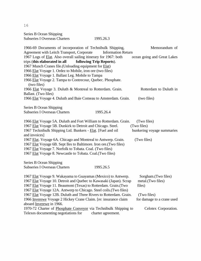
Series B Ocean Shipping
Subseries I Overseas Charters 1995.26.3
1966-69 Documents of incorporation of Technibulk Shipping, Memorandum of
Agreement with Leitch Transport, Corporate Information Return
1967 Logs of Elat. Also overall sailing itinerary for 1967: both ocean going and Great Lakes
trips (this elaborated in all following Trip Reports).
1967 Munch Cranes file.(Unloading equipment for Elat)
1966 Elat Voyage 1. Ordez to Mobile, iron ore (two files)
1966 Elat Voyage 1. Ballast Leg. Mobile to Tampa
1966 Elat Voyage 2. Tampa to Contrecour, Quebec. Phosphate.
(two files)
1966 Elat Voyage 3. Duluth & Montreal to Rotterdam. Grain. Rotterdam to Duluth in
Ballast. (Two files)
1966 Elat Voyage 4. Duluth and Baie Comeau to Amsterdam. Grain. (two files)
Series B Ocean Shipping
Subseries I Overseas Charters 1995.26.4
1966 Elat Voyage 5A. Duluth and Fort William to Rotterdam. Grain. (Two files)
1967 Elat Voyage 5B. Dunkirk to Detroit and Chicago. Steel. (Two files)
1967 Tecknibulk Shipping Ltd. Bunkers - Elat. [Fuel and oil bunkering voyage summaries
and invoices]
1967 Elat. Voyage 6A. Chicago and Montreal to Antwerp. Grain. (Two files)
1967 Elat Voyage 6B. Sept Iles to Baltimore. Iron ore.(Two files)
1967 Elat Voyage 7. Norfolk to Tobata. Coal. (Two files)
1967 Elat Voyage 8. Newcastle to Tobata. Coal.(Two files)
Series B Ocean Shipping
Subseries I Overseas Charters 1995.26.5
1967 Elat Voyage 9. Wakayama to Guayamas (Mexico) to Antwerp. Sorgham.(Two files)
1967 Elat Voyage 10. Detroit and Quebec to Kawasaki (Japan). Scrap metal.(Two files)
1967 Elat Voyage 11. Beaumont (Texas) to Rotterdam. Grain.(Two files)
1967 Elat Voyage 12A. Antwerp to Chicago. Steel coils.(Two files)
1967 Elat Voyage 12B. Duluth and Three Rivers to Rotterdam. Grain. (Two files)
1966 Inverewe Voyage 2 Hickey Crane Claim. [re: insurance claim for damage to a crane used
aboard Inverewe in 1966.
1970-72 Charter of Phosphate Conveyor via Technibulk Shipping to Celotex Corporation.
Telexes documenting negotiations for charter agreement.
17
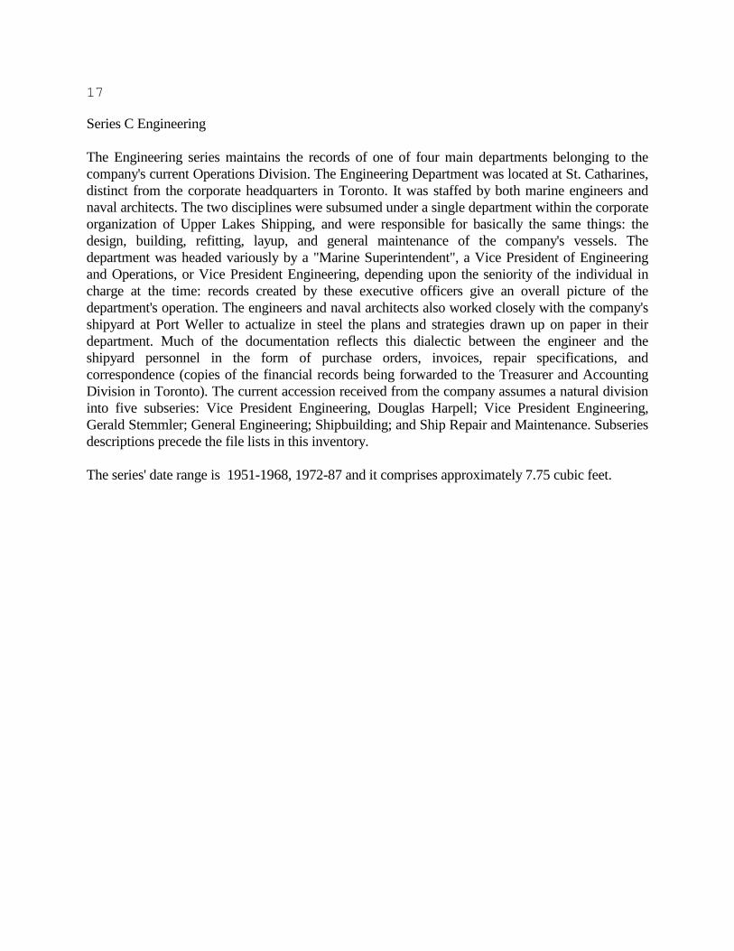
Series C Engineering
The Engineering series maintains the records of one of four main departments belonging to the
company's current Operations Division. The Engineering Department was located at St. Catharines,
distinct from the corporate headquarters in Toronto. It was staffed by both marine engineers and
naval architects. The two disciplines were subsumed under a single department within the corporate
organization of Upper Lakes Shipping, and were responsible for basically the same things: the
design, building, refitting, layup, and general maintenance of the company's vessels. The
department was headed variously by a "Marine Superintendent", a Vice President of Engineering
and Operations, or Vice President Engineering, depending upon the seniority of the individual in
charge at the time: records created by these executive officers give an overall picture of the
department's operation. The engineers and naval architects also worked closely with the company's
shipyard at Port Weller to actualize in steel the plans and strategies drawn up on paper in their
department. Much of the documentation reflects this dialectic between the engineer and the
shipyard personnel in the form of purchase orders, invoices, repair specifications, and
correspondence (copies of the financial records being forwarded to the Treasurer and Accounting
Division in Toronto). The current accession received from the company assumes a natural division
into five subseries: Vice President Engineering, Douglas Harpell; Vice President Engineering,
Gerald Stemmler; General Engineering; Shipbuilding; and Ship Repair and Maintenance. Subseries
descriptions precede the file lists in this inventory.
The series' date range is 1951-1968, 1972-87 and it comprises approximately 7.75 cubic feet.
18
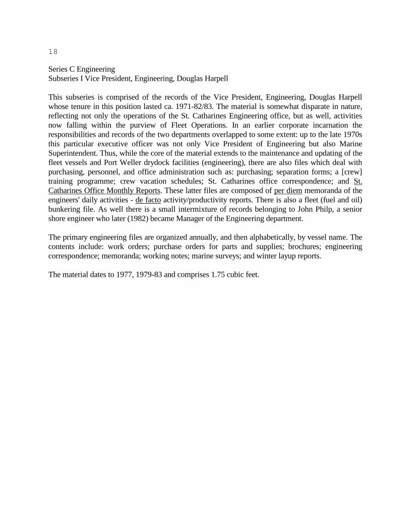
Series C Engineering
Subseries I Vice President, Engineering, Douglas Harpell
This subseries is comprised of the records of the Vice President, Engineering, Douglas Harpell
whose tenure in this position lasted ca. 1971-82/83. The material is somewhat disparate in nature,
reflecting not only the operations of the St. Catharines Engineering office, but as well, activities
now falling within the purview of Fleet Operations. In an earlier corporate incarnation the
responsibilities and records of the two departments overlapped to some extent: up to the late 1970s
this particular executive officer was not only Vice President of Engineering but also Marine
Superintendent. Thus, while the core of the material extends to the maintenance and updating of the
fleet vessels and Port Weller drydock facilities (engineering), there are also files which deal with
purchasing, personnel, and office administration such as: purchasing; separation forms; a [crew]
training programme; crew vacation schedules; St. Catharines office correspondence; and St.
Catharines Office Monthly Reports. These latter files are composed of per diem memoranda of the
engineers' daily activities - de facto activity/productivity reports. There is also a fleet (fuel and oil)
bunkering file. As well there is a small intermixture of records belonging to John Philp, a senior
shore engineer who later (1982) became Manager of the Engineering department.
The primary engineering files are organized annually, and then alphabetically, by vessel name. The
contents include: work orders; purchase orders for parts and supplies; brochures; engineering
correspondence; memoranda; working notes; marine surveys; and winter layup reports.
The material dates to 1977, 1979-83 and comprises 1.75 cubic feet.
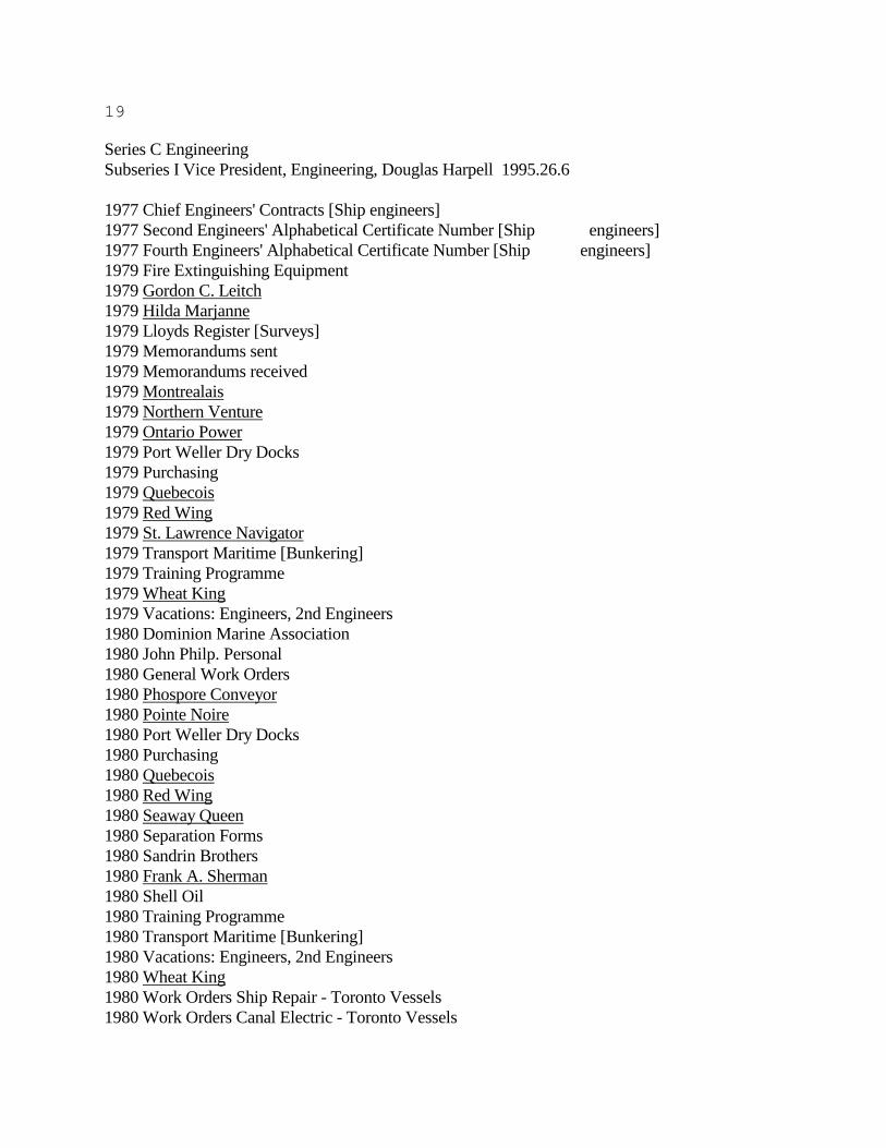
19
Series C Engineering
Subseries I Vice President, Engineering, Douglas Harpell 1995.26.6
1977 Chief Engineers' Contracts [Ship engineers]
1977 Second Engineers' Alphabetical Certificate Number [Ship engineers]
1977 Fourth Engineers' Alphabetical Certificate Number [Ship engineers]
1979 Fire Extinguishing Equipment
1979 Gordon C. Leitch
1979 Hilda Marjanne
1979 Lloyds Register [Surveys]
1979 Memorandums sent
1979 Memorandums received
1979 Montrealais
1979 Northern Venture
1979 Ontario Power
1979 Port Weller Dry Docks
1979 Purchasing
1979 Quebecois
1979 Red Wing
1979 St. Lawrence Navigator
1979 Transport Maritime [Bunkering]
1979 Training Programme
1979 Wheat King
1979 Vacations: Engineers, 2nd Engineers
1980 Dominion Marine Association
1980 John Philp. Personal
1980 General Work Orders
1980 Phospore Conveyor
1980 Pointe Noire
1980 Port Weller Dry Docks
1980 Purchasing
1980 Quebecois
1980 Red Wing
1980 Seaway Queen
1980 Separation Forms
1980 Sandrin Brothers
1980 Frank A. Sherman
1980 Shell Oil
1980 Training Programme
1980 Transport Maritime [Bunkering]
1980 Vacations: Engineers, 2nd Engineers
1980 Wheat King
1980 Work Orders Ship Repair - Toronto Vessels
1980 Work Orders Canal Electric - Toronto Vessels

20
1980 Work Orders Marsh Engineering - Toronto Vessels
1980 Work Orders Fritz - Toronto Vessels
1980 Work Orders - St. Catharines Layup
1980 Work Orders Frasers - Toronto Vessels
1980 Work Orders Miscellaneous - Toronto Vessels
n.d. Reference Files. Self Unloader Equipment
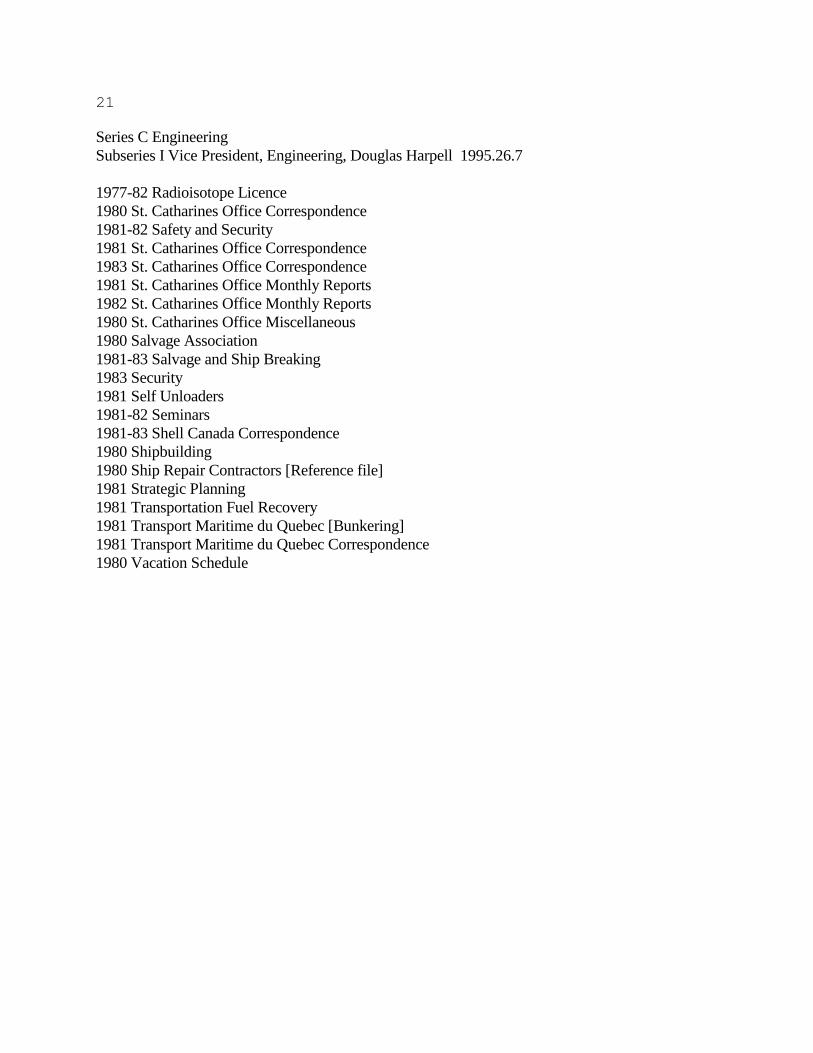
21
Series C Engineering
Subseries I Vice President, Engineering, Douglas Harpell 1995.26.7
1977-82 Radioisotope Licence
1980 St. Catharines Office Correspondence
1981-82 Safety and Security
1981 St. Catharines Office Correspondence
1983 St. Catharines Office Correspondence
1981 St. Catharines Office Monthly Reports
1982 St. Catharines Office Monthly Reports
1980 St. Catharines Office Miscellaneous
1980 Salvage Association
1981-83 Salvage and Ship Breaking
1983 Security
1981 Self Unloaders
1981-82 Seminars
1981-83 Shell Canada Correspondence
1980 Shipbuilding
1980 Ship Repair Contractors [Reference file]
1981 Strategic Planning
1981 Transportation Fuel Recovery
1981 Transport Maritime du Quebec [Bunkering]
1981 Transport Maritime du Quebec Correspondence
1980 Vacation Schedule

22
Series C Engineering
Subseries II Vice President, Engineering, Gerald Stemmler
This subseries follows thematically and chronologically, Subseries I Vice President Engineering
Douglas Harpell. It is consists of records from the St. Catharines engineering office of Vice
President, Engineering, Gerald Stemmler, who succeeded to the post in 1983/4 and continued to ca.
1991. The material corresponds in nature and organization to the previous subseries but is much
less comprehensive - for instance, there are only two vessel engineering files extant - both for the
Quetico. The date range is 1986-87 and comprise approximately 0.25 feet.
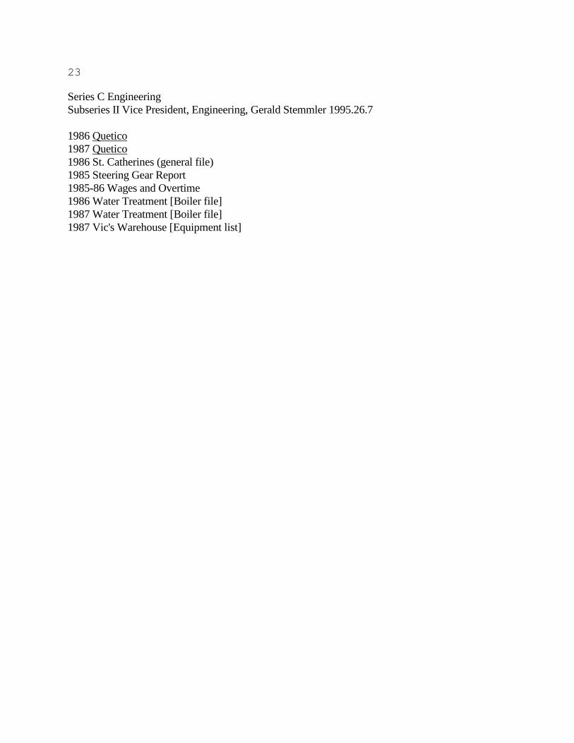
23
Series C Engineering
Subseries II Vice President, Engineering, Gerald Stemmler 1995.26.7
1986 Quetico
1987 Quetico
1986 St. Catherines (general file)
1985 Steering Gear Report
1985-86 Wages and Overtime
1986 Water Treatment [Boiler file]
1987 Water Treatment [Boiler file]
1987 Vic's Warehouse [Equipment list]

24
Series C Engineering
Subseries III General Engineering
This subseries is comprised of records from the St. Catharines Engineering office and document
specifically the ongoing fleet maintenance as directed by the marine engineers of ULS. Original
order has been preserved: the records are organized primarily by vessel name, and secondarily by
date (with some redundancy from box to box). The records are comprised of specifications, work
orders, boiler data, general engineering data, and engineering correspondence. Complementary
records may be found in the two Vice President Engineering Subseries I & II. Date range is
1961,1969, 1973-1986; the subseries comprises two cubic feet of material.
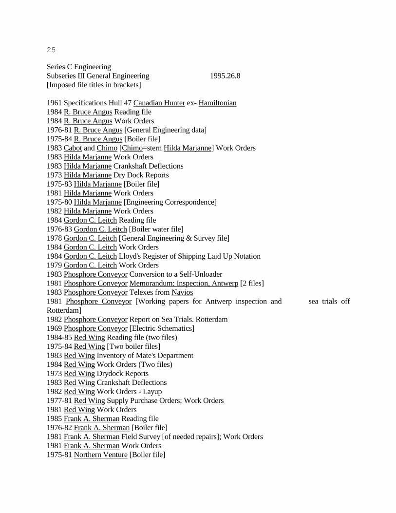
25
Series C Engineering
Subseries III General Engineering 1995.26.8
[Imposed file titles in brackets]
1961 Specifications Hull 47 Canadian Hunter ex- Hamiltonian
1984 R. Bruce Angus Reading file
1984 R. Bruce Angus Work Orders
1976-81 R. Bruce Angus [General Engineering data]
1975-84 R. Bruce Angus [Boiler file]
1983 Cabot and Chimo [Chimo=stern Hilda Marjanne] Work Orders
1983 Hilda Marjanne Work Orders
1983 Hilda Marjanne Crankshaft Deflections
1973 Hilda Marjanne Dry Dock Reports
1975-83 Hilda Marjanne [Boiler file]
1981 Hilda Marjanne Work Orders
1975-80 Hilda Marjanne [Engineering Correspondence]
1982 Hilda Marjanne Work Orders
1984 Gordon C. Leitch Reading file
1976-83 Gordon C. Leitch [Boiler water file]
1978 Gordon C. Leitch [General Engineering & Survey file]
1984 Gordon C. Leitch Work Orders
1984 Gordon C. Leitch Lloyd's Register of Shipping Laid Up Notation
1979 Gordon C. Leitch Work Orders
1983 Phosphore Conveyor Conversion to a Self-Unloader
1981 Phosphore Conveyor Memorandum: Inspection, Antwerp [2 files]
1983 Phosphore Conveyor Telexes from Navios
1981 Phosphore Conveyor [Working papers for Antwerp inspection and sea trials off
Rotterdam]
1982 Phosphore Conveyor Report on Sea Trials. Rotterdam
1969 Phosphore Conveyor [Electric Schematics]
1984-85 Red Wing Reading file (two files)
1975-84 Red Wing [Two boiler files]
1983 Red Wing Inventory of Mate's Department
1984 Red Wing Work Orders (Two files)
1973 Red Wing Drydock Reports
1983 Red Wing Crankshaft Deflections
1982 Red Wing Work Orders - Layup
1977-81 Red Wing Supply Purchase Orders; Work Orders
1981 Red Wing Work Orders
1985 Frank A. Sherman Reading file
1976-82 Frank A. Sherman [Boiler file]
1981 Frank A. Sherman Field Survey [of needed repairs]; Work Orders
1981 Frank A. Sherman Work Orders
1975-81 Northern Venture [Boiler file]

26
1978 Northern Venture Preventive Maintenance and Diagnostic Analysis; Work Orders
1985 Wheat King Reading file
1976-81 Wheat King [Boiler file]
nd. Ungava Transport Dismantling the Main Engine of the Ungava Transport

27
Series C Engineering
Subseries III General Engineering 1995.26.9
1975-77 Phosphore Conveyor Correspondence
1975-83 Phosphore Conveyor General (engineering data)
n.d. Phosphore Conveyor Index for Finished Plans
1981-86 Red Wing Work Orders
1981-85 Red Wing General (engineering data)
1985 Richmond Hill Work Orders
1982 Seaway Queen Work Orders
1981 Frank A. Sherman General (engineering data)
1981 Frank A. Sherman Megger Tests
n.d. Frank A. Sherman Spare Parts List
1981-86 Frank A. Sherman Work Orders
1975-81 Ontario Power General (engineering data)
1978-81 Ontario Power Miscellaneous Correspondence
1980-81 Ontario Power Work Orders
1982-83 Ontario Power Work Orders
1973 Ontario Power Ignitor Assembly
1981 Ontario Power Tampa Barge Service
1985-86 Wheat King General (engineering data)
1981 Wheat King Megger Tests
1981-82 Wheat King Miscellaneous Correspondence
1985-86 Wheat King Work Orders
1984-86 Fleet Work Orders
1985 Fleet Work Orders
28
Series C Engineering
Subseries IV Shipbuilding
This subseries is comprised of files from the engineering office at St. Catharines. They document
the building of new ULS vessels at Port Weller, and the purchase and conversion of vessels, both at
Port Weller and other yards. Note that no distinction was made between the professions of naval
architect and marine engineer at ULS: both disciplines and were merged under the umbrella of
marine engineering. The material includes specifically engineering records such as; specifications,
engineering correspondence, progress photographs, progress reports, machinery lists, and
calculations for stability and loading. As well there are associated records such as marine surveys
and vessel certificates, purchase orders for materials, and general correspondence.
Original order has been observed. Organization is by vessel name (with previous names irregularly
recorded); beyond that there is little apparent internal organization. The subseries currently
comprises approximately 1.75 cubic feet of material.
29
Series C Engineering
Subseries IV Shipbuilding 1995.26.10
1953 R. Bruce Angus. Hull Specification for The Conversion of the Great Lakes Oil Tanker
Imperial Redwater to A Great Lakes Ore and Bulk Carrier [R. Bruce Angus] at Collingwood
Shipyards.
1953,58 R. Bruce Angus. Spare Propellor, Tail shaft, rudder. [List and correspondence
regarding above parts]
1950 R. Bruce Angus. Anchors and Cables - Original Certificates.
1954-56 R. Bruce Angus ex Imperial Redwater. Conversion. [engineering correspondence,
sketches, purchase orders for material]
1951-54 R. Bruce Angus ex Imperial Redwater. Conversion. Progress Photographs.[44 black
and white photographs both bound and loose. Annotated]
Subseries IV Shipbuilding 1995.26.11
[Red Wing -ex Imperial Edmonton conversion]
1960 Red Wing. Description of: Major Conversion From T2 Tanker, Imperial Edmonton to
Lake Bulk Cargo Carrier.[Working draft and final copy]
1957 Imperial Edmonton Hull Renewals Schedule/Specification
1958 Photographs of T2 Tankers at New Haven. [Eight 5x7 prints]
1959-64 Red Wing. General correspondence
1958-59 Vickers Ocean-Lake Bulk Carrier Correspondence
1961 Red Wing conversion progress photographs.[96 prints=42, 4x5" and 54, 8x10 "; bulk are
black and white]
Subseries IV Shipbuilding 1995.26.11
[Wheat King ex Llandaff conversion]
1971 Thermometers.[Schematics, calculations, and 30 5x7" photographs]
1971 Bowthrusters.[Contents do not match file title; items all regarding fuel availability and
modifications required for arctic operation]
1960 Wheat King ex Llandaff Estimated Stability
1960 Wheat King Loading Calculations and Stability
1960 What King ex Llandaff Preliminary Specifications. Conversion to Bulk Carrier for Service
on Ocean and Great Lakes. One specification dated July 1960, three other copies datedd to
October 1960. Including thirteen progress photographs. [Four files]
1975 Wheat King. Inspections.
1976 Wheat King. Machinery.
1959 Llandaff a.k.a. Wheat King. Survey Report
1960 Wheat King. Report of Survey
1975 Wheat King. Contract with Port Weller Drydocks for lengthening of hull.
1957-59 Llandaff. Certificates: Boiler; Load Line; Radiotelegraphy; Hull and Machinery; Canal
Certificate; Panama Canal Certificate; Class Certiticate; Speed Trials; Compasses;
30
Venezualan Tonnage Certificate
Series C Engineering
Subseries IV Shipbuilding 1995.26.11
[Wheat King ex Llandaff]
1957 Transcript for Register. Safety Equipment Certificates.
1975 Wheat King. Purchase Orders.[1975 lengthening]
1975 Wheat King. Purchase Approvals.[1975 lengthening]
1952-57 Lllandaff. Registers of Machinery, Chains, Wire Rope, etc.
1957-61 Hull 25. Wheat King. [Miscellaneous]
1960 Llandaff.Conversion calculations and data to Wheat King.
1976 Correspondence. Wheat King. [1977-76 lengthening]
Subseries IV Shipbuilding 1995.26.11
[Canadian Olympic. New build at Port Weller]
1976 Canadian Olypic. Progress reports.
Subseries IV Shipbuilding 1995.26.12
[Ontario Power]
1965 Ontario Power. Tank Calibrations
1965 Ontario Power. Stability Book
1965 Ontario Power. Grain Loading Booklet
1965 Ontario Power. Report on the Second Trip of the Ontario Power
1965 Ontario Power. Report of Inclining Experiment
1965 Measured and Calculated Deflections of Ontario Power at Float Off [ie: launching
deflections]
1967 National Research Council of Canada. Mechanical Engineering Report. Main Hull Girder
Stresses. Ontario Power.
1964 Notes and Recommendations to Avoid Built in Sag in All Welded Ships
31
Series C Engineering
Subseries V Ship Repair and Maintenance
Two manners/modes of organization are to be found: in general maintenance files material is
ordered primarily by vessel name, secondarily by date; for fleet repair invoices the reverse holds
with material filed annually, then alphabetically by vessel name.
Files typically comprised of: engineering correspondence; plan lists; refit modification
schedules/lists;refit specifications; surveys; certificates; boiler data; tenders and bids from
subcontractors; occasional personnel items; service reports; and copies of itemized invoices for
repairs done (invoices being a direct source for refit information).

32
Series C Engineering
Subseries V Ship Repair and Maintenance 1995.25.13
[Goderich ex Pathfinder]
1964-65 Goderich [engineering correspondence re: refit]
1967-68 Goderich [engineering data and sketches re: refit including 28 5x7" black and white
progress photographs]
Subseries V Ship Repair and Maintenance 1995.25.13
[Goderich ex Pathfinder]
1964 Cape Breton Miner Grain Loading [Booklet]
1968 Cape Breton Miner [Correspondence re: refit
1972-76 Cape Breton Miner Lloyd's Certificates
1976 Cape Breton Miner Dry Docking and Refits
1974 Cape Breton Miner Marine Service Lubrication Chart
1976-77 cape Breton Miner Correspondence [engineering]
33
Series C Engineering
Subseries V Ship Repair and Maintenance 1995.26.14
[Repair Invoices for Fleet]
1981 Canadian Ambassador
1981 Canadian Century
1981 Canadian Enterprise
1981 Canadian Highlander
1981 Canadian Hunter
1981 Canadian Leader
1981 Canadian Navigator
1981 Canadian Pioneer
1981 Canadian Progress
1981 Canadian Prospector
1981 Canadian Transport
1981 Cape Breton Miner
1981 Frank A. Sherman
1981 Gordon C. Leitch
1981 Hilda Marjanne
1981 James Norris
1981 Montrealais
1981 Ontario Power
1981 Quebecois
1981 Pointe Noire
1981 R. Bruce Angus
1981 Red Wing
1981 Seaway Queen
1981 Wheat King
1981 Fleet
1982 Cape Breton Miner
1982 Frank A. Sherman
1982 gordon C. Leitch
1982 Hilda Marjanne
1982 Northern Venture
1982 Ontario Power
1982 Pointe Noire
1982 R. Bruce Angus
1982 Red Wing
1982 Wheat King
1983 Cabot [later stern of Canadian Explorer]
1983 Cape Breton Miner
1983 Chimo [later stern of Canadian Ranger]
1983 Frank A. Sherman
1983 Gordon C. Leitch

34
1983 Hilda Marjanne
1983 Northern Venture
1983 Ontario Power
1983 Phosphore Conveyor
1983 R. Bruce Angus
1983 Red Wing
1983 Wheat King
35
GRAPHIC SUBGROUP
The ship plan subgroup consists of approximately 33 cubic feet of graphic material which translates
into almost 2550 plans by count. These plans are almost exclusively blueprints (folded). Following
ship register convention, the plans are primarily arranged alphabetically, according to vessel name.
At the item level, the individual plans were often numbered by the company. They have remained
in this order, and are listed thus. Where no company number was found the plans were assigned
item level numbers from .1 onwards. Full accession numbers have been assigned at the archivist's
discretion - each box being allotted a main tripartite number, then each item's own number
concatenates to this to form a four element accession number for each plan. (Thus plan .23 in box
1995.26.25 is fully identified as plan 1995.26.25.23).
A fleet list from The Ships of Upper Lakes Shipping by Garnet Wilcox and Skip Gillham has been
included in the introduction to this subgroup to orient the reader and facilitate identification of
vessels.
UPPER LAKES SHIPPING FLEET LIST
Including present and past ships
Ambassador
Angus, R. Bruce
Arctic
Arctic Troll
Baird, Frank B.
Barge 137
Blue Cross
Blue River
Brown Beaver
Brawn Barge
Bad, Ralph
Canadian Ambassador
Canadian Century
Canadian Enterprise
Canadian Explorer
Canadian Highlander
Canadian Hunter
Canadian Leader
Canadian Mariner
Canadian Navigator
Canadian Olympic
Canadian Pioneer
Canadian Progress
Canadian Prospector
Canadian Ranger
36
Canadian Transport (I)
Canadian Transport (II)
Cape Breton Highlander
Cape Breton Miner
Citadel Hill
UPPER LAKES SHIPPING FLEET LIST
Including present and past ships (continued)
Clement, Norman P.
Daniels, William H.
Douglass, Edwin T.
Eads, James B.
Ericsson, John
Federal Monarch
Field, Albert C.
Fritz, John
Glenbogie
Goderich
Grey Beaver
Grovedale
Hamilton Energy
Hart, Judge
Hilda Marjanne
Holley, Alexander
Hollaway, John A.
Houghton, Douglass
Huntley, Charles R.
Inverewe
Kenefick, Judge
Leitch, Gordon C.
Maunaloa II
MacPherson, Norman B.
McGrath, James E.
McCorquodale, L.A.
Meaford
Melanie Fair
Montrealais
Nelvana
Nisbet, Watkins F.
Norris, James
Northern Venture
Ontario Power
Parkdale

37
Phosphore Conveyor
Pillsbury, John S.
Pioneer
Pointe Noire
Pomeroy, Robert W.
Port Weller
Quebecois
Rammacher, John H.
Red Wing
Richards, John H.
Richmond Hill (I)
Richmond Hill (II)
Ridgetown
Roebling, John A.
St. Lawrence Navigator
St. Lawrence Prospector
UPPER LAKES SHIPPING FLEET LIST
Including present and past ships (continued)
Sarnian
Seaway Queen
Shaw, Howard L.
Sherman, Frank A.
Stewart, James
Taylor, Shirley G.
Thornhill (I)
Thornhill (II)
Thornhill (III)
Torian, George L.
Victorious
Wallaceburg
Warren, William C.
Weed, Shelton
Wheat King
Wiarton

38
Canadian Explorer 1995.26.15
ex- Northern Venture[bow]
ex- Cabot[stern]
Port Weller/-/1984
Accession #/Title/Drawing #/Date
.1/Capacity Plan/Dwg - /1973
.2/Mallkantenplan Und Massskizze/Dwg 556/557-002009/1960
.3/Hydrostatic Curves/Dwg 556-0010-02/1961
.4/General Arrangement/Dwg - /1961
.5/Cargo Hold-Wing-Bulkheads FRS 83,109,135,163,191/Dwg 556- 1303d/1960
.6/Bulkheads On Upper-Deck (Aft)/Dwg 556-1507a/1960
.7/Zu Und Abluft Der Wohnraume Im I. Und Backdeck Vorschiff/Dwg 556/557-3120-01/1961
.8/Installation Of The Upper Deck And Forecastle Deck/Dwg 556-9000- 06a/1960
.9/New Duct Arrm. Poopdeck/Dwg 556-3103/1961
.10/Supply And Exhaust Air Of Accomodation Rooms In Upper Deck, Frame 19-45/Dwg 556-
3120-03/1961
.11/Gyro System And Gyro Steering/Dwg 556-9000-21a/1960
.12/Arrangement Of Zinc Protectors On Stern Frame And Rudder/Dwg 556-0020-29/1960
.13/Chain Locker/Dwg 556-1004/1960
.14/Sea Box Strainer/Dwg 556-8000-06b/1960
.15/Arrangement Of Rudder Equipment/Dwg 556-10-15/1960
.16/Arrangement Of Rudder Equipment/Dwg 556-10-15/1960
.17/Stern Anchor Pocket/Dwg 556/557-1105/1960
.18/Bower Anchor Pocket/Dwg 556/557-1106a/1960
.19/Tank Top/Dwg 556-1201/1960
39
.20/Upper Deck/Dwg 556-1410/1960
.21/Upper Deck Forw./Dwg 556-1413a/1960
.22/Bridge Deck/Dwg 556-1414a/1960
.23/Forecastle Deck/Dwg 556 1417a/1960
.24/Bulkheads On Upper Deck/Dwg 556-1505a/1960
.25/Bulkheads On Upper Deck (Aft)/Dwg 556-1507a/1960
.26/Bulkheads On Upper Deck (Aft)/Dwg 556 1507a/1960
.27/Bulkheads On Poopdeck/Dwg 556-1509/1960
.28/Anderung Des Poop-Front-Schotts Und Deckuberstand/Dwg 556-15- 13a/1960
.29/Oberlicht Zum Crews Recreations Room/Dwg 556-1530-01/Date -
.30/Boom Step For 2 t. Load/Dwg 556/557-2020-02b/1961
.31/Rudder Tiller Casting Model/Dwg 556-2100-02/1960
.32/Steering Gear Motor Assembly/Dwg 556-2100-04/1961
.33/Steering Gear Motor Assembly/Dwg 556-2100-04/1961
.34/Arrangement Of Port Colborne Fairleads On Maindeck/Dwg 556/557- 2330-07/1960
.35/Diagram Arrangement Of Fwd. Ventilation/Dwg ?/1960
.36/Coverstion Of Sea Chest For Potable Water Fill Pump/Dwg 556- 8030-03a/1960
.37/Elevation Engine And Boiler Room Stbd. Side/Dwg 556-6100- 04b/1960
.38/Poopdeck Reefer Space - Refrigeration Insulation/Dwg 556- 2520-04a/1960
.39/Poopdeck Reefer Space - Refrigeration Insulation/Dwg 556- 2520-04a/1960
.40/Supply And Exhaust Air Of Accomodation Rooms In Upper Deck, Frame 19-45/Dwg 556-
3120-03/1961
40
.41/Supply And Exhaust Air Of Accomodation Rooms In Upper Deck, Frame 19-45/Dwg 556-
3120-03/1961
.42/New Duct Arrm. Poop Deck/Dwg 556-3103/1961
.43/New Duct Arrm. Boat Deck/Dwg 556-31-01/1961
.44/Supply And Exhaust Air Of Accomodation Rooms In Back Deck And Upper Deck
Forebody/Dwg 556/557-3120-01/1961
.45/New Duct Arrm. Upper Deck/Dwg 556-31-02/1960
.46/New Duct Arrm. Upper Deck/Dwg 556-31-02/1960
.47/New Duct Arrm. Upper Deck/Dwg 556-31-02/1960
.48/Supply And Exhaust Air Of Accomodation Rooms In Upper Deck, Frame 0-19/Dwg 556-
3120-04/1961
.49/Exhaust Air For Crew Recreation Room/Dwg 556-3120-05/1961
.50/Piping - Foreward/Dwg 556-8000-22/1961
.51/Insulation Plan/Dwg 556-3700-01b/1961
.52/Quarters Arrangement Upper Deck Forward A. Forecastle Deck/Dwg 556-4300-03/1960
.53/Sea Box Strainer/Dwg 556-8000-06b/1960
.54/Arrangement Of Sanitary System Aft And Fwd./Dwg 556-8030- 01/1960
.55/Diagrammatic Of Main Water Piping In Engine Room/Dwg 556-8030- 02/1960
.56/Conversion Of Sea Chest For Potable Water Fill. Pump/Dwg 556- 8030-03a/1960
.57/Diagrammatic Arrangement Of Sewage System/Dwg 556-8040-06a/1960
.58/Engine And Boiler Room Extraction And Waste Steam Piping Diagram/Dwg 556-8100-
02/1960
.59/One Line Diagram/Dwg 557-9000-01/1960
.60/Diagrammatic Of Drain Piping/Dwg 556-8110-02/Date -

41
.61/Installation Of The Upper Deck And Forecastle Deck/Dwg 556- 9000-06a/1960
.62/Gyro System And Gyro Steering/Dwg 556-9000-21a/1960
.63/Wiring Diagram For Ballast Pump 2 And Connection For Aft Winch Power Panel/Dwg 556-
9110-02/1960
.64/Diagrammatic Arrangement Of Bilge - , Ballast - , And Priming System/Dwg 556-8000-
02d/1960
.65/Diagrammatic Arrangement Of Bilge, Ballast, And Priming System/Dwg 556-8000-
02d/1960
.66/Sanitary Discharge Lines/Dwg 556-8040-07c/Date -
.67/Diagrammatic Arrangement Of Compressed Air Lines/Dwg 556-6160- 01/1960
.68/Connection For Fwd. Winch Power Panel, And Connection For Measurement/Dwg 556-
9110-03/1960
.69/Diagrammatic Arrangement Of Bilge, Ballast, And Priming System/Dwg 556-8000-
02d/1960
.70/Diagrammatic Arrangement Of New Auxiliary Steam Piping.Dwg 556- 8100-03/1960
.71/Fire Extinguishing Plan/Dwg 556-8050-01/1960
.72/Fire Extinguishing Plan/Dwg 556-8050-01/1960
.73/Hydrostatic Curves/Dwg 556-0010-02/1961
.74/Hydrostatic Curves/Dwg 556-0010-02/1961
.75/Docking Plan/Dwg 556-0010-15/1961
.76/Docking Plan/Dwg 556-0010-15/1961
.77/Docking Plan/Dwg 556-0010-15/1961
.78/Arrangement Of Life-Saving Equipment/Dwg 556/557-32-01c/1960
.79/Mooring Arrangement Upper Deck/Dwg 556/557-23-01a/1960
.80/Anchor Arrangement On Stern/Dwg 556/557-22-02c/1960
42
.81/Bower Anchor Arrangement/Dwg 556/556-22-01b/1961
.82/Arrangement Of Scupper/Dwg 556-8040-03b/1961
.83/Diagrammatic Arrangement Of Vent And Sounding Pipes/Dwg 556- 8060-03/1960
.84/Scupperplant/Dwg 556-8040-01a/1960
.85/Storm Valve Welded Discharge Pipe/Dwg 556-8040-08/1960
.86/Suction Bellmouth/Dwg 556-8000-05a/1960
.87/Masts For Noc-Lights, Anchor Lights And Signalling Lamp/Dwg 556/557-2740-01/1961
.88/Passageway Exhaust Air Fr. 25-26P Fr. 26-27S/Dwg 556-3120- 02/1961
.89/Steam For Running Engineroom/Dwg 556-3140-07/1961
.90/Ventilation Of Passage-Ways/Dwg 556/557-3160-02a/1961
.91/Ventilation Of Stores, Etc. In Fore Body/Dwg 556-3160-01/1960
.92/Hallways And Decks For Crew's Recreation Room 83/Dwg 556-41- 06/1961
.93/Walls, Hallways And Decks For Crew's Messroom And Poopdeck/Dwg 556-41-07/1961
.94/Steel Doors/Dwg 556/557-3302d/1960
.95/Drawing For Windows/Dwg 556-33-01/1961
.96/Supply And Exhaust Air For CO2 Room/Dwg 556-3160-06/1961
.97/Dutch Type Door In Shell-Plating/Dwg 556/557-3310-02/1960
.98/Outside Dead Light For Windows/Dwg 556-3380-04/1961
.99/Inside Dead Light For Windows/Dwg 556-3380-02/1961
.100/Stewards Stores Poopdeck Room 38/Dwg 556-4680-03/1961
.101/Deck Store Upperdeck Forward Room 26a/Dwg 556-4680-04/1961

43
.102/Duplex Priming Unit/Dwg 652/1960
.103/Priming System/Dwg 651/1960
.104/Lamproom/Dwg 556/557-4680-05/1960
.105/Owner's Pantry Room 9/Dwg 556-4710-13a/1960
.106/Laundry Room 77 Upper Deck Aft/Dwg 556-4750-01/1960
.107/Table Lamp/Dwg 556-4800-01/1960
.108/Ships Name (Bow)/Dwg 556-5260-01a/1961
.109/Arrangement Of E-Station Upperdeck/Dwg 556-4640-11a/1961
.110/Installation E-Log/Dwg 556-9000-30b/1960
.111/Installation Of Consumer In The Pantry/Dwg 556-9000-27a/1961
.112/Cable Way In The Cable Trunk/Dwg 556-9030-03/1961
.113/Installation Of Engine Order Telegraph And Plant Mills/Dwg 556-9000-22/1960
.114/Installation Of Rudder Angle Indicator And Revolution Counter/Dwg 556-9000-
23a/1960
.115/Mold Loft Offsets/Dwg - /1961
.116/Exhaust Air For Laundry p./Dwg 556-3120-06/1961
.117/Exhaust Air Of Mess Room - Officers And Crew/Dwg 556-3120- 09/1960
.118/Watertight Flap Arrangement I/Dwg 556-3130-01/1960
.119/Arrangement Of Gyro Room/Dwg - /1961
.120/Arrangement Of Nautical Equipment In The Pilot House/Dwg 556- 4-15b/1960
.121/Owner's Cabin/Dwg 556-4-12a/1960
.122/Self Closing Vave/Dwg 556-8040-05/1960
44
.123/Inventory List For Deck Department/Dwg 556-28-01/Date -
.124/Section Through Wall/Dwg 556-41-05/1960
.125/Captain's Dayroom/Dwg 556-4-10a/1960
.126/Supply And Exhaust Air For Paint Locker/Dwg 556-3160-03/1961
.127/Officer's Mess Room - Arrangement Of Galley Door 556 And 557/Dwg 556-41-
09/1961
.128/Alteration Of Rails In Aft Body/Dwg 556/557-3500-02/1962
.129/Captain's Bedroom/Dwg 556-4-11a/1960
.130/Painting/Dwg 556-5-32a/1960
.131/Farben Und Konservierungsplan Fur Alle Neuen Und Aufgearbeiteten
Eisenteile/Dwg 556/557-5-31/1960
.132/Arrangement Of Pilot's Room/Dwg 556-4-17/1961
.133/Recreation Room Forward/Dwg 556-4-16/1960
.134/Lamp Screen For Spare Rangelamp/Dwg 556/557-2700-03a/Date -
.135/Signal Mast Aft/Dwg 556-2700-02a/1960
.136/Arrangement Of Port Colborne Fairleads On Upper Deck/Dwg 556/557-2330-07b/1960
.137/Namepennant/Dwg 556-2840-01/1960
.138/Bitter Eno Fittings For Bower Anchor Chains/Dwg 556/557-2230- 01/1960
.139/Bolt For Rudder Tiller/Dwg 556-2100-03/1960
.140/Bitter End Fittings For Stern Anchor Chains/Dwg 556/557-2260- 01/1960
.141/Slider (Stern)/Dwg 556/557-2260-03a/1960
.142/Grand View Boiler-Room And Platform Deck Engine-Room/Dwg 556- 6100-02b/1960
.143/Funnelmark N.B. 556/Dwg 556-5260-03/1961
45
.144/Arrangement Of Whistles In The Funnel/Dwg 556/557-7800-03/1961
.145/Notabschaltung Fur Pumpen/Dwg 556-9000-17a/1961
.146/Arrangement Of Navigation Lamps/Dwg 556/557-9320-02/1960
.147/Installation Of Fathometer/Dwg 556-9000-13a/1960
.148/Installation Of The Trimmindicator Fwd. And Aft/Dwg 556-9000- 16a/1961
.149/Arrangement Of Cable For Quick-Closing Controls At Diesel Oil Tanks/Dwg 556-8130-
09/1961
.150/Sea Water Heater/Dwg 59-998-1/1960
.151/Steam Lines At Hot Water Boiler In Forebody/Dwg 556-8100- 04/1960
.152/Comensator (#10004) F. Safety Line/Dwg 556-8170-02/1960
.153/Overall Dimensions Of Extra Heavy Marine Viking Johnson Couplings For Steel
Pipes/Dwg 556-8000-04/1960
.154/Arrangement Of Pilot-House/Dwg 556-4-08b/1960
.155/Quarters Arrangement Upper Deck Fwd. a. Forecastle Deck/Dwg 556-4-03f/1961
.156/Quarters Arrangement Upper Deck Aft/Dwg 556-4-01d/1960
.157/Quarters Arrangement Poop Deck/Dwg 556-4-02c/1960
.158/Main And Bridge Deck Fwd./Dwg 556-4-09b/1960
.159/Linen Locker Upper Deck Aft Room 87/Dwg 556-4680-01/1961
.160/Navigation Bridge/Dwg 556-4440-01/1961
.161/Chest For Radar Transmitter And Folding Table/Dwg 556-4440- 02/1961
.162/Pad Eyes For Boatswain's Chair/Dwg 556/557-2880-57/1961
.163/Supply And Exhaust Air For Steering Gear Room/Dwg 556-3140- 01/1960
.164/Blocking For Rotating Ventilator Caps/Dwg 556-3120-14a/1961

46
.165/Label Schedule (Page 1)/Dwg 556-2870-03a/1961
.166/Label Schedule (Page 2)/Dwg 556-2870-03a/1961
.167/Label Schedule (Page 3)/Dwg 556-2870-03a/1961
.168/Deadweight Calculation/Dwg - /1961
.169/Conversion Of Sea Chest For Potable Water Fill Pump/Dwg 556- 8030-03a/1960
.170/Diagram Arrangement Of Fwd Ventilation/Dwg - /1960
.171/Steering Gear Motor Assembly/Dwg 556-2100-04/1961
.172/Bulkheads On Upper Deck (Aft)/Dwg 556-1507a/1960
.173/Deadweight Calculation/Dwg - /1961
.174/Protocols Of Trials/Dwg - /1961
.175/Capacity Plan/Dwg 556-0010-16/Date -
.176/Frame Plan/Dwg 556-1103/1960
.177/Ventilation Plant/Dwg 556-31-06/1961
.178/Calculation Of Trim/Dwg - /1961
.179/Detail "A" From Dwg No. 556.1014a/Dwg 556 1016/1961
.180/Deckdurehbruche Fur Ruder M. Roum Luftung (Alt)/Dwg 3140- 02/1960
.181/Turenplan Fur Kammer-Moskito U. Ruderhausturen [Joiner Door Plan]/Dwg 556-4300-
07c/1960
.182/Diagrammatic Arrangement Of Bilge - , Ballast - , And Priming System/Dwg 556-8000-
02d/1960
.183/New Duct Arrm. Poop Deck/Dwg 556-3103/1961

47
Canadian Explorer 1995.26.16
ex. Northern Venture (bow)
ex. Cabot (stern)
Port Weller/-/1984
Accession #/Title/Drawing #/Date
.1/General Arrangement - Profile/Dwg 649-A.F.-500-1/Date -
.2/General Arrangement - Spar Deck And Top Decks/Dwg 649-A.F.-500- 2/Date -
.3/General Arrangement - Main Deck-Steering Gear Flat-Tank Top/Dwg 649-A.F.-500-3/Date -
.4/General Arrangement - Main Deck-Steering Gear Flat-Tank Top/Dwg 649-A.F.-500-3/Date -
.5/Capacity Plan/Dwg 649-A.F.-501/1965
.6/Capacity Plan/Dwg 649-A.F.-501/1967
.7/Capacity Plan/Dwg 649-A.F.-501/1967
.8/Lines Plan/Dwg 649-A.F.-502/1965
.9/Lines Plan/Dwg 649-A.F.-502/1965
.10/Lines Plan/Dwg 649-A.F.-502/1965
.11/Hydrostatic Curves/Dwg 649-A.F.-503/1965
.12/Hydrostatic Curves/Dwg 649-A.F.-503/1965
.13/Hydrostatic Curves/Dwg 649-A.F.-503/1965
.14/Trim And Stability Particulars - Conditions With Only One Crane On Board/Dwg - /1967
.15/Trim And Stability Particulars - Conditions With Only One Crane On Board/Dwg - /1967
.16/Trim And Stability Particulars/Dwg 649-A.F.-504/1965
.17/Trim And Stability Particulars/Dwg - /1967
.18/Trim And Stability Particulars/Dwg - /1967
.19/Cross Curves OF Stability/Dwg 649-A.F.-506/1965

48
.20/Cross Curves Of Stability/Dwg 649-A.F.-506/1965
.21/Profile And Decks Aft Body/Dwg 649-A.F.-507/Date -
.22/Shell Expansion/Dwg 649-A.F.-509/Date -
.23/Shell Expansion/Dwg 649-A.F.-509/Date -
.24/Docking Plan/Dwg 649-A.F.-510/Date -
.25/Docking Plan/Dwg 649-A.F.-510/Date -
.26/Docking Plan/Dwg 649-A.F.-510/Date -
.27/Ship's Name And Draft Marks/Dwg 649-3072-2/1965
.28/Lines Plan (Fwd)/Dwg 3653-11 (Sheet 2)/1964
.29/General Arrangement Profile/Dwg 649-9000-1/1965
.30/General Arrangement Profile/Dwg 649-9000-1/1964
.31/Visibility With Cranes In Stowed Position And Arrangement Of Containers/Dwg 649-2046-
1/1964
.32/Hatch Cover Operating Instructions/Dwg 8820/1964
.33/Hatch Cover Operating Instructions/Dwg 8820/1964
.34/Stowage Plan No. 1 Hatch/Dwg 8148/1964
.35/No. 1 And No. 4 Hatch Closing Operation/Dwg 649-2014-2/1965
.36/Double Bottom (Hold)/Dwg 649-120-1/1964
.37/Double Bottom (Hold)/Dwg 649-120-1/1964
.38/Main Deck Plating (Between Frs. 11 and 144)/Dwg 649-120-8/1964
.39/Main Deck Plating (Between Frs. 11 and 114)/Dwg 649-120-8/1964
.40/Water Ballast Tank In Lower Hold Fwd./Dwg 649-120-15/1964
.41/General Arrangement Profile - Proposal "A"/Dwg 649-9000-1/1964
49
.42/General Arrangement Pfofile - Proposal "B"/Dwg 649-9000-1/1964
.43/Proposed Arrangement For Elevators/Dwg P.106-3083-1/1963
.44/Proposed Arrangement For Elevators/Dwg P.106-3083-1/1963
.45/Proposed Access To Aft. Hold/Dwg 649-3062-101/1964
.46/Quick Acting Cleat/Dwg - /Date -
.47/Quick Acting Cleat For Hatch Sides/Dwg 649-2014/1965
.48/Quick Acting Cleat For Hatch Sides/Dwg 649-2014/1965
.49/Hatch End Beams And Strong Beams In Holds For Main Deck/Dwg 649-120-4 (Sheet
1)/1964
.50/Hatch End Beams And Strong Beams In Holds For Main Deck/Dwg 649-120-4 (Sheet
1)/1964
.51/Hatch End Beams And Box Beams In Holds For Spar Deck/Dwg 649- 120-4 (Sheet 2)/1964
.52/Hatch End Beams And Box Beams In Holds For Spar Deck/Dwg 649- 120-4 (Sheet 2)/1964
.53/Shell Expansion/Dwg 649-120-2/1964
.54/Trimming Hatches/Dwg 649-3019-3/1964
.55/Fore End Framing/Dwg 649-120-6/1964
.56/Fore End Framing/Dwg 649-120-6/1964
.57/Lower Hold Wt. Bhds./Dwg 649-120-30/1964
.58/Lifting Spreader (30 Ton) (Aluminum)/Dwg 649-2046-4/1965
.59/Lifting Spreader (30 Ton) (Aluminum)/Dwg 649-2046-4/1965
.60/Arrangement Of Scuppers For W.T. Cargo Doors/Dwg 649-4085- 16/1964
.61/Arrangement Of Scuppers For W.T. Cargo Doors/Dwg 649-4085- 16/1964
.62/Arrangement Of Elevator Piping/Dwg 649-4225-11/1964
50
.63/Arrangement Of Elevator Piping/Dwg 649-4225-11 (Sheet 2)/Date -
.64/Hydrolic Piping Arrangement For Cargo Doors/Dwg 649-4225-10 (Sheet 1)/1964
.65/Hydrolic Piping Arrangement For Cargo Doors/Dwg 649-4225-10 (Sheet 2)/Date -
.66/Hydrolic Piping Arrangement For Cargo Doors/Dwg 649-4225-10 (Sheet 2)/Date -
51
Canadian Harvest 1995.26.17
ex - Rimouski
Collingwood/Hull 181/1964
Accession #/Title/Drawing #/Date
.1/Dwg H-8200/ G.A. Profile/1964
.2/Dwg H-8201/G.A. Upper Decks/1964
.3/Dwg H-8202/G.A. Lower Decks/Date -
.4/Dwg H-8203/Midship Section/1964
.5/Dwg H-8204/Shell Expansion & Framing Plan/1964
.6/Dwg H-8205/Capacity Plan/1972
.7/Dwg H-8206/Hydrostatic Curves/1972
.8/Dwg H-8207/Lines Plan/Date -
.9/Dwg H-8208/Docking Plan/1965
.10/Dwg H-8209/After Cant Frames, Web Fr. 245, & After Chain Locker/1964
.11/Dwg H-8210/W.T. Bhd 30, Web Fr. 27/1964
.12/Dwg H-8211/W.T. Bhd 204/1964
.13/Dwg H-8212/Lower Deck Plating Frs 30 & 23 & W.T. Bulkhead Under/1964
.14/Dwg H-8213/Fore Peak Construction/1964
.15/Dwg H-8214/Side Tanks Upper/1964
.16/Dwg H-8215/Side Tanks Lower/1964
.17/Dwg H-8216/Aft Peak Construction/1964
.18/Dwg H-8217/Oil Fuel Bunkers/1964
.19/Dwg H-8218/Tank Top & Double Bottom in Holds/1964
52
.20/Dwg H-8219/Spar Deck Plating at Ends/1964
.21/Dwg H-8220/Spar Deck Between Hatches/1964
.22/Dwg H-8221/Main Deck Plating/1964
.23/Dwg H-8222/Machinery Deck/1964
.24/Dwg H-8223/False Floors - Spar, Poop & Forecastle Decks/1964
.25/Dwg H-8224/Forward Trimming Bulkheads/1964
.26/Dwg H-8225/Accommodation Plan - Poop & Forecastle Decks/1964
.27/Dwg H-8226/Laundry- Main Deck Forward/1964
.28/Dwg H-8227/Laundry- Main Deck Aft./1964
.29/Dwg H-8228/Laundry- Spar Deck Aft./1964
.30/Dwg H-8229/Passengers' Pantry - Forecastle Deck/1964
.31/Dwg H-8230/Captain's Pantry - Texas Deck/1964
.32/Dwg H-8231/Painting Room - Spar Deck Aft./1964
.33/Dwg H-8232/Painting Room - Main Deck Aft./1964
.34/Dwg H-8233/Bosun's Store - Spar Deck Aft./1964
.35/Dwg H-8234/Locker Room - Main Deck Aft./1964
.36/Dwg H-8235/Cold Stores/1964
.37/Dwg H-8236/Mooring Arrangement/1964
.38/Dwg H-8237/W.T. Roller Bow Fairlead/1964
.39/Dwg H-8238/Fabricated Towing Chock/1965
.40/Dwg H-8239/Section in Way of Lifeboats/1964
.41/Dwg H-8240/Boat Arrangement (Missing) - see H-8269
53
.42/Dwg H-8241/Accommodation Ladder Arrangement/1964
.43/Dwg H-8242/Fore & Aft. Ladder Arrangement/1965
.44/Dwg H-8243/Stores Davit Seating/1965
.45/Dwg H-8244/Landing Boom & Details/1965
.46/Dwg H-8245/Oil Hose Davit/1965
.47/Dwg H-8246/Hydraul;cally Operated Spear Pole/1964
.48/Dwg H-8247/Accommodation Ladder Davits/1965
.49/Dwg H-8248/Emergency Whistle Pull/1965
.50/Dwg H-8249/Aft Mast & Details/1964
.51/Dwg H-8250/Forward Mast & Details/1964
.52/Dwg H-8251/Rigging Plan/1965
.53/Dwg H-8252/Lifeline Arrangement/1965
.54/Dwg H-8253/Exterior Painting Scheme & Ship's Name (missing)
.55/Dwg H-8254/Hull Insulation/1964
.56/Dwg H-8255/Deck Coverings/1964
.57/Dwg H-8256/Wheelhouse Chartroom & Wheelhouse Top/1965
.58/Dwg H-8257/Rudder/1964
.59/Dwg H-8258/Rudder Stock/Date -
.60/Dwg H-8259/Forged Steel Pintle/1964
.61/Dwg H-8260/Stern Frame/Date -
.62/Dwg H-8261/Steering Gear Seating/1964
.63/Dwg H-8262/Rudder Alteration (Missing)

54
.64/Dwg H-8263/Fire Detection/1985 (Date issued)
.65/Dwg H-8269/Section in Way of Lifeboats/1964
55
Canadian Harvest 1995.26.18
ex - Rimouski
Collingwood/Hull 181/1964
Accession #/Title/Drawing #/Date
.1/Machinery Arrangement Plan Views/Dwg E-2321/1964
.2/Machinery Arrangement Sections & Elevation/Dwg E-2308/1964
.3/Pumping Plan/Dwg 181-C-101/1964
.4/Hot Water Piping Diagrammatic/Dwg E-2331/1964
.5/Piston Cooling Piping Diagrammatic/Dwg H-2667/1964
.6/Main Ballast Pump Sea Chest/Dwg G-3861/1964
.7/Filter Tank for Piston Cooling Water/Dwg G-3875/1964
.8/Lube Oil Diagrammatic/Dwg E-2328/1964
.9/Lube Oil Piping/Dwg E-2355/1965
.10/Fuel Oil Service Piping/Dwg E-2344/1964
.11/Fuel Oil Piping Diagrammatic/Dwg E-2323/1964
.12/Fuel Oil Service Piping/Dwg E-2343/1964
.13/Fuel Valve Cooling Fresh Water Piping Diagrammatic/Dwg H- 2668/1964
.14/Waste & Drains/Dwg 181-C-107/1964
.15/Air Piping Diagrammatic/Dwg G-3865/1964
.16/Sea Water Piping Diagrammatic/Dwg G-3862/1964
.17/High & Low Sea Inlet Boxes/Dwg E-2320/1964
.18/Preliminary Ballast Piping Arrangement/Dwg E-2231/1963
.19/Fresh Water Piping Diagrammatic/Dwg H-2666/1964
.20/Fuel Oil Piping Diagrammatic/Dwg E-2323/1964
56
.21/Shafting Arrangement/Dwg E-2311/1964
.22/Sterntube Details/Dwg E-2315/1964
.23/Fuel Oil Service Piping/Dwg E-2343/1964
.24/Fuel Oil Filling & Sludge Pump Discharge/Dwg E-2322/1964
.25/Sterntube Fittings Detail/Dwg E-2288/1964
.26/Fuel Oil Filling, Venting & Sounding Piping/Dwg E-2319/1964
.27/Bilge, Ballast & General Service Diagrammatic/Dwg G-3848/1964
.28/Ballast Control Panel/Dwg H-2659/1964
.29/Sanitary Water System/Dwg 181-C-108/1964
.30/C.P. Propeller Lube Oil Diagrammatic/Dwg G-3874/1964
.31/Auxiliary Machinery Seats in Lower Engine Room/Dwg 181-C- 47/1964
.32/Primary Piping Diagrammatic/Dwg H-2685/1964
.33/High Pressure Hot Water Piping/Dwg E-2362/1965
.34/Hot & Cold Water Systems/Dwg 181-C-109/1964
.35/Cooling Water to Ice Machine & A/C Condensers/Dwg 181-C- 110/1965
.36/Diesel Exhaust Piping/Dwg E-2361/1965
.37/Engine Room Project New Bulk Carrier/Dwg 181-P-39/1960
.38/Disposition der Rohranschlusse/Dwg 181-P-40-1/1962
.39/Rohrplan Seitenansichten & Schnilt Durch Zylinder/Dwg 181-P-40- 2/1959
.40/Rohrplan Ansicht Auspuffseite/Dwg 181-P-40-3/1959
.41/Rohrplan Ansicht Brennstoffpumpenseite/181-P-40-4/1959
.42/Rohrplan Grundriss & Kurbelgehause/Dwg 181-P-40-5/1959
57
.43/Draft Indicators/Dwg 181-C-116/1964
.44/Shafting for Emergency Steering/181-C-217/1964
.45/Outside Scuppers/Dwg 181-C-113/1964
.46/Natural Ventilation/Dwg 181-C-112/1964
.47/Ventilation in Engine Room Plan Views/Dwg E-2334/1964
.48/Ventilation Arrangement for Elect. Control Room & Bow Thruster Comp./Dwg 181-C-
119/1964
.49/Ventilation in Engine Room Sections & Elevations/Dwg E- 2336/1964
.50/Mechanical Ventilation/Dwg 181-C-111/1964
.51/Electric Lighting Schematic/Dwg EL-181-D-531/1964
.52/Diagrammatic Layout of Control Piping for Automatic Ballast
Discharge Regulating Valve/Dwg G-3899/1965
.53/Turning Gear/Dwg 3-200230/1964
58
Canadian Hunter 1995.26.19
ex- Petite Hermione
ex- Hamiltonian
Saint John Shipbuilding & Drydock Co. Ltd./Hull 47/1960
Accession #/Title/Drawing #/Date
.1/General Arrangement/Dwg 119/1960
.2/Upper Deck Plating Forward/Dwg 53C Sheet 2/1961
.3/Upper Deck Plating Aft/Dwg 47-53C Sheet 1/1961
.4/Profile & Decks/Dwg 33/1960
.5/Poop Deck Plating/Dwg 53D/1960
.6/Shell Expansion-Forward/Dwg 40C/1961
.7/Aft Framing Expansion/Dwg 47A/1960
.9/Shell Expansion Midships/Dwg 40B/1961
.10/Shell Expansion Aft/Dwg 40A/1960
.11/Midship Section/Dwg 34/1960
.12/Arrangement of Scuppers & Discharges Poop Deck, Upper Deck/Dwg 414/1960
.13/Plan of Manholes/Dwg 85/1961
.14/List of Doors & Hardware/Dwg 47-83/1960
.15/Detail of Doors/Dwg 47-83A/1960
.16/Engineers Office & Locker Room/Dwg 113J/1961
.17/Arrangement of Cargo Hold Floodlights/Dwg 47-115/1960
.18/Fresh & Distilled Water Tanks on Main Deck Aft/Dwg 74/1960
.19/Sea Suction Boxes/Dwg 58/1961
.20/Pumping Arrangement inc.,Air & Sounding, Scuppers From Lower Dks./Dwg 47-405/1961
59
.21/Main Engine Seats/Dwg 54/1961
.22/Heating Coils in F.O. Settling Tanks/Dwg 353 Sheet 2/1961
.23/Lead of After Control Shafting/Dwg 116/1961
.24/Welding Sequence Upper Dk. Aft/Dwg 70C/1961
.25/Welding Sequence Tank Top & D.B. in E.R./Dwg 70B/1961
.26/Heating Coils in Bunkers & D.B. Tanks/Dwg 47-353 Sheet 1/1961
.27/Welding Sequence Shell Aft/Dwg 70A/1961
.28/Tailshaft Removal/Dwg 318/1961
.29/Auxiliary Engine Seats Tank Top/Dwg 57A/1960
.30/Deck Coverings/Dwg 89/1961
.32/Location & Details of Shipside Discharge Valve Mountings/Dwg 356/1961
.33/Engine Room Floor Plates Ladders & Gratings/Dwg 361/1962
.34/As Fitted Sea Water Circulating Pipe Arrangement/Dwg 348/1962
.35/As Fitted Miscellaneous Piping in Eng Room Arrangement/Dwg 347 Sheet 1/1962
.36/Miscellaneous Piping in Eng Room Arrangement As Fitted/Dwg 347 Sheet 2/1962
.38/Minor Bulkheads-Main Dk. Aft/Dwg 56A/1961
.39/Steel Hatch Covers/Dwg 61 Fly A/1961
.40/Hatch Covers/Dwg 61 Fly A/1962
.41/Upper Deck Forward Accommodation/Dwg 47-110B-2/1961
.42/Upper Deck Plating Aft/Dwg 47-53C Sheet 1/1961
.43/Upper Deck Plating Forward/Dwg 53C Sheet 2/1961
.44/Forecastle Deck Plating/Dwg 53E/1961

60
.45/Bilge & Ballast Arrangement in Engine Room/Dwg 345/1961
.45A/Ballast Pump Schematic & Wiring Diagram/Dwg 12087-E-8/1987
.46/Condensate, Distillate And Vents Arrangement -As Fitted- (Sections)/Dwg 349 (Sheet
1)/1962
.47/Condensate, Distillate And Vents Arrangement -As Fitted- (Profiles)/Dwg 349 (Sheet
3)/1962
.48/Condensate, Distillate And Vents Arrangement -As Fitted- (Plans)/Dwg 349 (Sheet
2)/1962
.49/Auxiliary Boiler Feed Water Tank/Dwg 395/1962
.50/Arrangement Of Scuppers And Drains Main Deck And Control Platform -As Fitted-/Dwg
414 (Sheet 1)/1962
.51/Arrangement Of Scuppers And Drains -As Fitted-/Dwg 414 (Sheet 3)/1962
.52/Main And Auxiliary Steam -As Fitted- (Profile)/Dwg 348 (Sheet 1)/1962
.53/Main And Auxiliary Steam -As Fitted- (Plan)/Dwg 348 (Sheet 2)/1962
.54/Arrangement Of Feed And Boiler Blowdowns -As Fitted-/Dwg 350/1962
.55/Arrangement Of Pumping Flooding And Draining/Dwg - /1962
.60/Auxiliary Boiler Feed Water Tank/Dwg 395/1962
.61/Arrangement Of Fuel Oil Filling And Transfer/Dwg 340/1962
61
Canadian Hunter 1995.26.20
ex Petite Hermine
ex Hamiltonian
Saint John Shipbuilding & Drydock Co. Ltd./47/1960
Accession #/Title/Drawing #/Date
.1/Engine Room Ventilation/Dwg 370/1962
.2/Uptakes & Inner Funnel/Dwg 371/1962
.3/F.O. Drain Tank/Dwg 390 Sheet 1/1961
.4/D.O. Storage, D.O. Day & O.W. Separator Reclaim Tanks/Dwg 390 Sheet 2/1962
.5/Arrangement & Details of Landing Booms & Sounding Boom/Dwg 93C/1961
.6/Rigging Arrangement/Dwg 47-93/1961
.7/Echo Sounder Compartment/Dwg 48 Fly 1/1962
.8/Bulwarks/Dwg 62/1961
.9/Shell Door/Dwg 71/1961
.10/Minor Bulkheads on Upper Deck Fwd./Dwg 65B/1961
.11/Decks-Houses & Minor Bhds. Above Forecastle Deck/Dwg 65C/1962
.12/Lamp & Paint Room/Dwg 113F/1961
.13/Draft Marks & Paint Line/Dwg 96/1961
.14/Laundry & Dryroom/Dwg 113C/1962
.15/Compressed Air Arrangement As Fitted/Dwg 344/1962
.16/Extended Spindles/Dwg 365 Sheet 1/1962
.17/Extended Spindles/Dwg 365 Sheet 2/1962
.18/Extended Spindles @ Fr 234/Dwg 365 Sheet 3/1962
.19/Safety Valve Easing Gear Detail & Arrangement/Dwg 363/1962
62
.20/Diagramatic Arrangement of Sea Water Circ. System/Dwg 326/1961
.21/Diagramatic Arrangement of Drinking Water, Sanitary Water & Fire & Washdeck/Dwg
1047-327/1961
.22/Exhaust Steam Drains and Escape Arrangement Center Line Profile to Port and Stbd./Dwg
47-351/1962
.23/Arrangement of Indicating Systems for Ballast Tanks, Ships Draught, Bunker & Misc.
Tanks & Telegraphs/Dwg 355/1962
.24/Diagrammatic Arrangement Feed & Boiler Blowdowns/Dwg 336/1961
.25/Diagrammatic Arrangement of Condensate, Distillate & Vents/Dwg 329/1961
.26/Diagrammatic Arrangement Bilge, Ballast & Priming Systems/Dwg 325/1961
.27/Rope Guard/Dwg 314/1962
.28/Oil Fuel Service Diagram/Dwg 321/1960
.29/Oil Fuel Pumping Diagram/Dwg 320/1960
.30/Main Engine Holding Down Bolts & Chocks/Dwg 305/1961
.31/Heating Coils in F.O. Settling Tanks/Dwg 353/1961
.32/Diagrammatic Arrangement Main & Auxiliary Steam/Dwg 328/1961
.33/Tank Top & Double Bottom Engine Room/Dwg 55A/1960
.34/Aft End Framing/Dwg 49/1960
.35/Heating Coils in Settling Tanks/Dwg 353/1961
.36/Shafting Arrangement/Dwg 310/1960
.37/Diagrammatic Arrangement of Lube Oil Service & Transfer Piping/Dwg 336/1961
.38/Hydrostatic Curves/Dwg D43/1962
.39/F.O. Service Arrangement As Fitted/Dwg 341/1962
63
.40/Main & Aux. Steam System/Dwg 348 Sheet 1/1961
.41/Main & Aux. Steam System/Dwg 348 Sheet 2/1961
.42/Main & Aux. Steam System/Dwg 348 Sheet 3/1961
.43/Lube Oil Service and Transfer Piping As Fitted/Dwg 342/1961
.44/Tank Top & Double Bottom Aft Hold/Dwg 55B/1960
.45/Rails & Stanchions/Dwg 81/1961
.46/Funnel & Fan Room/Dwg 66/1962
.47/Minor Bulkheads on Main Deck Fwd./Dwg 56B/1961
.48/Arrangement of Engine Room Servicing Hoists/Dwg 302/1961
.49/Auxiliary Engine Seats Control Platform/Dwg 57B/1961
.50/Lube Oil Settling, Storage, Gravity & Miscellaneous Tanks/Dwg 398/61
.51/System Flooding, Pumping & Draining List of Valves & Fittings/Sheets 1-11/1961
.52/Main Machinery Arrangement Profile & Sections/Dwg 301/1961
.53/Sketch of After Accomadation/1961
.54/Arrangement Of Scuppers & Discharges - Profile - /Dwg 414/1961
.55/List Of Insulation/Dwg 382/1962
.56/Upper Deck Aft Accommodation/Dwg 47-110A/1961
.57/Upper Deck Forward Accommodation/Dwg 47-110B/1961
.58/Stern Anchor Details - Showing Hawsepipes, Windlass Stiffening, Cable Locker Etc./Dwg
60/1961
.59/ 100 Gal. Observation Tank/Dwg 396/1961
.60/Lifeboat Stowage/Dwg 94A/1962
.61/General Alarm System/Dwg 47-506/1962
64
.62/Painting Schedule/Dwg 95/1962
.63/Ships Name And Port Of Registry/Dwg 98B/1962
.64/Ventilation Arrangement For Mooring Winch Motors/47-88D/1961
.65/Main Condenser Door Removal/Dwg 362 (Sheet 3)/1962
.66/Fore End Framing/Dwg 48/1961
.67/Exhaust Steam Drains And Escape Arrangement Plans/Dwg 351 (Sheet 1)/1962
.68/Mechanical Ventilation Arrangements/Dwg 88 (Sheet 1)/1962
.69/Mechanical Ventilation Arrangements/Dwg 88 (Sheet 2)/1962
.70/Mechanical Ventilation Details/Dwg 88A/1962
.71/Layout Of Air Conditioning Unit Room No. 1/Dwg 88B (Sheet 1)/1962
.72/Layout Of Air Conditioning Unit Room No. 2/Dwg 88B (Sheet 2)/1962
.73/CO2 Room/Dwg 113G/1962
.74/Lighting Decks -As Fitted- /Dwg 501 (Sheet 1)/1962
.75/Lighting Machinery Spaces -As Fitted- /Dwg 501 (Sheet 2)/1962
.76/Life Saving Appliances And Navigational Lights/Dwg 94/1961
.77/Arrangement Of Refrigerated Chambers/Dwg 102/1961
.78/Key Plan And List Of Sidelights And Windows/Dwg 82/1961
.79/Small Hatches - Key Plan And Details/Dwg 85A/1961
.80/Lifting Eye Plates And Zinc Anodes/Dwg 80/1961
.81/Linings, Ceilings And Joiner Bulkheads/Dwg 114/1961
.82/Insulation Key Plan And Details/Dwg 90/1961
.83/Diagrammatic Arrangement Of Drinking Water, Sanitary Water, Fire And Washdeck

65
Systems/Dwg 327/1961
.84/Mooring & Towing Arrangement/Dwg 91/1961
.85/Roller Fairlead At Bow And Stern/Dwg 91A/1961
.86/Key Plan Of Ladders/Dwg 84/1961
.87/Details Of Steel Stairways And Ladders/Dwg 84A/1961
.88/Stiffening Under Decks/Dwg 53 (Fly 1)/1963
.89/Arrangement And Details Of Spearpole/Dwg 93B/1961
.90/Details Of Ensign Staff And Oil Fuel Filling Davits/Dwg 93E/1961
.91/E.R. Lifting Beams/Dwg 75/1962
.92/Diagrammatic Arrangement Of Compressed Air Piping/Dwg 324/1961
.93/List Of Canvas/Dwg 104/1962
.94/Lighting Machinery Spaces/Dwg 501 (Sheet 2)/1961
.95/Arrangement Of Electrical Control Room Forward/Dwg 11B/1961
.96/Auxiliary Engine Seats Main Deck//Dwg 57C/1961
.97/Arrangement Of Scuppers And Discharges Wheelhouse Deck, Texas Deck, Forecastle Deck,
Upper Deck, And Main Deck/Dwg 414/1961
66
Canadian Hunter 1995.26.21
ex. Petite Hermine
ex. Hamiltonian
Saint John Shipbuilding and Drydock/Hull 47/1960
Accession #/Title/Drawing #/Date
.1/Natural Ventilation Details/Dwg 87a/1962
.2/Engine Room Layout Boilers AFT/Dwg - /1960
.3/Engine Room Layout Boilers Forward/Dwg - /1960
.4/Comparison Of Boilers Placed At Forward And After End Of Machinery
Compartment/Dwg - /1960
.5/A.T. Bulkhead 47/Dwg - /1961
.6/ 100 Gal. Observation Tank/Dwg 396/1961
.7/Extended Spindles/Dwg 365/1962
.8/Dry Store And Slop Lockers/Dwg 113b/1962
.9/Baggage Rooms Oil Skin Lockers And Linen Lockers/Dwg 113d/1962
.10/Layout Of Galley/Dwg 47-111/1961
.11/Engine Room And Galley Skylights/Dwg 86/1961
.12/Fire Fighting Arrangement/Dwg 124/1962
.13/Tank Top And Double Bottom Forward Hold/Dwg 55c/1961
.14/Tank Top And Double Bottom Forward Hold/Dwg 55c/1961
.15/Tank Top And Double Bottom Aft Hold/Dwg 55b/Date -
.16/Key Plan Of P.5. Plating/Dwg 73/Date -
.17/Layout Of Engineers Workshop/Dwg 47-372/1961
.18/Fire Fighting Appliances/Dwg 47-99/1960
.19/Arrangement And Details Of Stores Booms/Dwg 93d/1961

67
.20/Pantries/Dwg 113h/Date -
.21/Detail Of Shelving And Dole Plates In Refrigerated Chambers/Dwg 102b/1962
.22/Potable Water Tank On Main Deck Forward/Dwg 74a/Date -
.23/Water Tank For Winter Layup/Dwg 395 (Sheet 3)/Date -
.24/Forecastle Deckhouse,Texas Deck And Wheelhouse Accommodation/Dwg 47-
110c-3/1961
.25/List Of Insulation/Dwg 382/1962
.26/Hatch Cover Crane Rails/Dwg 79/1961
.27/Sea Water Circulating Pipe Arrangement/Dwg 346/1961
.28/Wing Tank Walkway/Dwg 47-105/1961
.29/Grain Shovel Lugs In Holds/Dwg 47-93a/1961
.30/Longitudinal Cargo Hold Bulkheads/Dwg 47-H52b/1961
.31/Preliminary Machinery Arrangement (Sections)/Dwg 47-300 (Sheet 1)/1961
.32/Preliminary Machinery Arrangement/Dwg 47-300 (Sheet 2)/1961
.33/Web Frs. And Stringers (Aft)/Dwg 50/1960
.34/Fly To O.T. And W.T. Bulkheads/Dwg 47-52a Fly/1961
.35/Control Platform Plating/Dwg 53a/1960
.36/Forward Framing Expansions/Dwg 47b/1961
.37/Navigation Lamp Box/Dwg 121/1962
.38/Arrangement Of Scuppers And Drains Upper And Poop Deck/Dwg 414/1962
.39/Bilge And Ballast Piping Arrangement/Dwg 345/1961
.40/O.T. W.T. And Screen Bulkheads/Dwg 47-52a/1960
68
.41/O.T. W.T. And Screen Bulkheads/Dwg 47-52a/1960
.42/Oil Fuel Settling Tank/Dwg 72/1961
.43/Loudhailing And Talk-Back System Connection Diagram/Dwg 47- 512/1962
.44/Furniture List/Dwg 47-97/1961
.45/Furniture Details/Dwg 47-97a (Sheets 1-20)/1961
.46/Monogram For St.John N.B. Quote Sept. 16/Dwg - /1961
.47/Upper Deck Aft Accommodation/Dwg 47-110a-2/1961
.48/Loudhailer And Talk-Back System & Telephone System/Dwg 47- 505/1962
.49/Evap. Door Removal Gear/Dwg 362 (Sheet 4)/1962
.50/Arrangement Of Electric Hydraulic Steering Gear/Dwg A. 4940/1956
.51/Steering Gear Seats/Dwg 68a/1961
.52/Forward Anchor Details - Showing Anchor Pockets, Hawsepipes, Chainpipes, Windlass
Stiffening Etc./Dwg 59/1961
.52/Mushroom Head For Ballast Tank Air Pipes/Dwg - /1961
.53/Bosun's Store/Dwg 113a/1961
.54/Fly To Midship Section/Dwg 34 (Fly)/1960
.55/Fly To Midship Section/Dwg 34 (Fly)/1960
.56/Drain Plugs In Shell And Tank Testing Plan/Dwg 47-78/1961
.57/Navigation Aids And Miscellaneous Diagrams As Fitted/Dwg 47- 504/1962
.58/KaMeWa - Steering Propeller 1000/2000/AS-CP Installation/Dwg 531806/1974
.59/KaMeWa - Steering Propeller 1000/2000/AS-CP Axelarrangem/Shaft Arrangement/Dwg
587167/1974
.60/Hull Equipment Certificates/Dwg - /Date -
69
.61/Machinery Equipment Certificates/Dwg - /Date -
.62/Capacity Plan/Dwg - /1972
.63/Capacity Plan/Dwg - /1972
.64/Capacity Plan/Dwg - /1962
.65/Capacity Plan/Dwg - /1962
.66/List Of Equipment/Dwg - /Date -
.67/Specification/Dwg - /Date -
.68/Shell Expansion - Forward/ Dwg 40c/1961

70
Canadian Pathfinder 1995.26.22
ex. Baie St. Paul
Davie Shipbuilding/-/1963
Accession #/Title/Drawing #/Date
.1/Dwg H-15603/Midship Section/1963
.2/Dwg H-15603/Midship Section/1963
.3/Dwg H-15606/Hydrostatic Curves/1963
.4/Dwg H-15625/Shell Expansion/1962
.5/Dwg H-15625/Shell Expanbsion/1962
.6/Dwg H-15671/Rudder & Details/1962
.7/Dwg H-15671/Rudder & Details/1962
.8/Dwg H-15671A/Upper Rudder Stock/1960
.9/Dwg H-15671A/Upper Rudder Stock/1960
.10/Dwg H-15672/Ship Side Connections/1962
.11/Dwg H-15672/Ship Side Connections/1962
.12/Dwg H-15673/Steering Gear Seats & Details for Machy. Rudder Stock/1962
.13/Dwg H-15673/Steering Gear Seats & Details for Machy. Rudder Stock/1962
.14/Dwg H-15674/ 70" Angle Valve w/14" Si de Outlet./1962 ex "Baie St. Paul"
.15/Dwg M-15600/Main & Auxiliary H.P. Steam Diagram/1962
.16/Dwg M-15601/L.P. Steam System Diagram/1962
.17/Dwg M-15602/Aux. Exhaust Bleed & Escape Steam System Diagram/1962
.18/Dwg M-15604/Main & Auxiliary Condensate System Diagram/1962
.19/Dwg M-15605/Engine Room Lifting Gear/1962
.20/Dwg M-15606/Tailshaft & Sterntube Assembly/1962
71
.21/Dwg M-15607/Shafting Arrangement/1962
.22/Dwg M-15608/Shaft Details/1962
.23/Dwg M-15609/Main & Auxiliary Feed System Diagram/1962
.24/Dwg M-15610/Main & Auxiliary Sea Water Circulating and Sea Water Service Systems
Diagram/1962
.25/Dwg M-15611/Compressed Air System Diagram/1963
.26/Dwg M-15612/Fresh Water & Sea Water Systems Diagram for 500KW Diesel
Generator/1962
.27/Dwg M-15613/List of Symbols for Piping Diagrams/1962
.28/Dwg M-15614/Fuel Oil and Diesel Oil Systems Diagram/1962
.29/Dwg M-15615/Lubricating Oil System Diagram/1962
.30/Dwg M-15616/Fireye Flame Failure Safeguard Control System/1966
.31/Dwg M-15617/Air, Fuel Oil, Steam & Control Piping for Semi- Automatic Boilers/1966
.32/Dwg M-15618/Air, Oil, Steam & Control Piping For Semi-Automatic Boilers/1965
.33/Dwg M-15631/Main Engine Forced Lubrification System Piping Arrangement/1963
.34/Dwg M-15634/Compressed Air System Piping Arrangement/1963
.35/Dwg M-15635/Priming System Piping Arrangement/1963
.36/Dwg M-15641/Piping in Lube Oil Sump Tank/1963
.37/Dwg M-15642/Heating Coils in Oil Fuel Bunkers/1962
.38/Dwg M-15643/Machinery Space Ventilation & Diesel Exhaust Plan View/1963
.39/Dwg M-15687/Primary Wheel Thrust Block/Date -
72
.40/Dwg M-15689/ 6" Ahead - 5" Astern Manoeuvring Emergency Valve/1962
.41/Dwg M-15813/F.W. Circulating Systems Diagram/1966
.42/Dwg H-15835/Stern Frame/1965
.43/Dwg H-15836/Rudder/1966
73
CANADIAN RANGER 1995.25.23
ex HILDA MARJANNE (bow)
ex CHIMO (stern)
Hull 57/Kaiser Shipyards/1943
Hull 662/Davie Shipyards/nd
Conversion/Port Weller Shipyards/1983
Accession #/Title/Drawing #/Date
.1/Arrangement of Deck Piping Aft/Dwg 214-900-1/1943
.2/Arrangement of Steam & Exhaust Piping Elevations Dwg 241-900- 6/1943
.3/Lines/Dwg K-700-8/1943
.4/Arrangement of Steam & Exhaust Piping Plans/Dwg 241-900-7/1943
.5/Arrangment of Steam & Exhaust Piping Sections/Dwg 241-900-8/1944
.6/Isometric of Main Steam Piping/Dwg 900-9-0/1943
.7/Arrangement of Water Piping Plans/Dwg 241-901-6/1943
.8/Arrangement of Water Piping Port & Starboard Elevation/Dwg 241- 901-7/1943
.9/Arrangement of Water Piping Sections at Fr. 36 to 45/Dwg 241- 901-8/943
.10/Arrangement of Main and Auxiliary Boiler Feed Piping/Dwg 241- 901-15/1943
.11/Main and Auxiliary Boiler Feed Piping Isometric/Dwg 901-15- 0/1943
.12/Diagrammatic of Compressed Air System/Dwg 241-902-01/1943
.13/Arrangement of Compressed Air Piping/Dwg 241-902-1/1943
.14/Diagram of Heating System/Dwg 241-914-01/1943
.15/Arrangement of Heating System. Forward Quarters/Dwg 241-914- 1/1943
.16/Arrangement of Heating. Aft Quarters/Dwg 241-914-2/1943
74
.17/Diagram of Drinking Water Systems/Dwg 241-918-011/1943
.18/Arrangement of Bilge & Ballast System in Engine & Boiler Rooms/Dwg 241-918-3/1944
.19/Key Rigging Plan/Dwg K-744-1/1943
.20/Kingposts & Fittings/Dwg K-744-21/1943
.21/Booms & Fittings/Dwg K-744-22/1943
.22/Arrangement of Engine Room Ventilators/Dwg K-777-2/1943
.23/Arrangement of Machinery Sections at frs. 40 & 42 (for G.E. Propulsion Equipment)/Dwg
KM-901-4/1943
.24/ 4" & 5" Scuppers for Sanitary System/Dwg KM-918-2/1943
.25/Arrangement & Details of Whistle Pulls/Dwg KM-942-1/1943
.26/Arrangement & Details of Whistle Pulls/Dwg KM-942-2/1943
.27/Offsets (final)/Dwg K-700D-0B/1942
.28/General Arrangement SS Castle Pinckney/Dwg K-700-1/1943
.29/Arrangement of Quarters Aft/Dwg K-700-2/1943
.30/Arrangement of Quarters Forward & Midship/Dwg K-700-3/1943
.31/Isometric Lighting, Midship Section/Dwg KS64-1-299B/1943
.32/Gyro System Wiring Diagram and Instruments/Dwg KS24-7-112/1943
.33/Rudder Angle Indicating System Schematic Diagram/Dwg KS24-7- 120/1942
.34/Instument Layout/Dwg KS24-7-186/1943
.35/Auxiliary Generators Cable Runs/Dwg KS-62-2-89/1942
.36/Conduit Detail on Walkway Between Bridge Deck & Pump House/Dwg KS-62-2-106/Date
-
.37/Detail of Conduit on Forward Walkway/Dwg KS-62-2-107/1943

75
.38/Power & Lighting Boiler Room/Dwg KS-62-2-208/1943
.39/Power/Dwg KS-63-1-125/1943
.40/Pumproom Lighting & Control Equipment/Dwg KS63-1-128/1943
.41/Bridge Space/Dwg KS64-1-91/1943
.42/Wiring Layout Upper Deck Forward/Dwg KS-64-1-96/1943
.43/Wiring Layout Forecastle and Gun Platform/Dwg KS 64-1-98/1942
.44/Wiring Layout Second Deck/Dwg KS 64-1-97/1942
.45/Wiring Layout Upper Deck Quarters-Aft-/Dwg KS64-1-149/1943
.46/Lighting and Power Layout Poop Deck/Dwg Ks64-1-158/1943
.47/Wiring Layout for Casing Top/Dwg KS-64-1-160A/1943
.48/Wiring Layout for Boat Deck/Dwg KS 64-1-160-B/1943
.49/Upper Bridge Deck Power Lighting and I.C./Dwg KS64-1-184/1943
.50/Wiring Layout House Top/Dwg KS-64-1-185/1942
.51/Wiring Layout Nav. Bridge Deck/Dwg KS-64-1-188/1943
.52/Bridge Deck Lighting Power and I.C. Layout/Dwg KS64-1-245/1943
.53/Isometric-Lighting-Aft/Dwg KS64-1-299A/1943
.54/Lighting Isometric Forepeak Section/Dwg KS64-1-299C/1943
.55/Isometric Wiring Diagram Battle Telephone/Dwg KS-65-1-295/1943
.56/Generator Flat-Port Frames 41-46/Dwg Ks-65-7-147/1943
.57/Schematic Whistle Control System/Dwg KS-65-7-304-B/1943
.58/Schematic Shaft Speed Indicator/Dwg KS-65-7-304-F/1943
.59/Isometric Wiring Diagram Fathometer & Rudder Angle Indicator System/Dwg KS68-0-
297/1943

76
.60/Fathometer System Elementary Diagram/Dwg KS68-1-192/1943
.61/Refrigeration-Machinery Location Nd Piping Layout/Dwg 241-855- 1/1943
.62/Arrangement of Telemotor Piping/Dwg 241-858-4/Date -
.63/Arrangement of Fuel Oil Transfer System in Eng. Room/Dwg 241- 869-01/1943
.64/Details of Ducts for Boiler Room Ventilation/Dwg K-777-4/1943
.65/Details of Ducts for Engine Room Ventilation/Dwg K-777-5/1943
.66/Ventilator for Fwd.End of Engine Room Under Machinery Flat/Dwg K-777-8/1943
.67/General Arrangement Natural Ventilation/Dwg K-778-1/1943
.68/Mechanical Ventilation Aft Quarters General Arrangement/Dwg K- 779-1/1943
.69/Mechanical Ventilation Aft Quarters & Fan Room - General Arrangment/Dwg K-779-
2/1943
.70/Mechanical Ventilation Aft Quarters Details of Ducts/Dwg K-779- 3/1943
.71/Mechanical Ventilation Aft Quarters Details of Ducts/Dwg K-779- 4/1943
.72/Mechanical Ventilation Aft Quarters-Details of Ducts/Dwg K-779- 5/1943
.72A/Exhauster-Aft Pump Room General Arrg't & Details/Dwg K-779- 6/1943
.73/Ventilation Ammunition Chamber Aft/Dwg K-779-8/1944
.74/General Arrangement Of Exhausters/Dwg K-779-12/1943
.75/Freeboard Markings/Dwg K-794-20/1943
.76/Isometric of Bilge and Ballast in Engine and Boiler Room/Dwg 918-3-0/1943
.77/Arrangement of Sanitary System Aft Quarters/Dwg 241-918-5/1943
.78/Diagramatic Arrangement of Steam Smothering Syst./Dwg 241-920- 02/1942
.79/Arrangement of Piping for CO2 Fire Extinguishing System/Dwg 241-920-2/1944

77
.80/CO2 Fire Extinguishing System In Machinery Spaces, Control Station Cabinets/Dwg 241-
920-3/1944
.81/General Arrangement Of CO2 Fire Protection Control Stations/Dwg 241-920-4/1944
.82/Power Failure Alarm Unit/Dwg CAL-7962S-5/1944
.83/Propeller/Dwg KM-840-1/1943
.84/Arrangement Lifting Gear, Steering Gear Flat/Dwg KM-856-27/1943
.85/Rudder Trunk/Dwg KM-858-2/1943
.86/Detail Of Rudder Stock And Eye Bolt/Dwg KM-858-3/1943
.87/Arrangement Of Telemotor Equipment/Dwg KM-858-4/1943
.88/Arrangement And Details Of Operating Gear For Rudder Angle Transmitter And
Indicator/Dwg KM-858-6/1943
.89/Arrangement And Details Of Steering Gear Control Shafting/Dwg KM-858-7/1943
.90/Protection For Telemotor Pipes Along Fore and Aft Walkway/Dwg KM-858-8/1943
.91/Details Of Rudder Bearing/Dwg KM-858-9/1943
.92/Detail Of Thrust Collar On Rudder Stock/Dwg KM-858-10/1943
.93/Rudder Bracket/Dwg KM-858-11/1944
.94/Uptakes/Dwg KM-880-1/1943
.95/Uptake Details/Dwg KM-880-2/1943
.96/Arrangement Of Machinery Plans (For G. E. Propulsion Equipment)/Dwg KM-901-
1/1943
.97/Arrangement Of Machinery Elevation (For G. E. Propulsion Equipment)/Dwg KM-901-
2/1943
.98/Arrangement Of Machinery Sections Frs. #9 To #30/Dwg KM-901- 3/1943
.99/Contra-Guide Rudder/Dwg K-703-2/1943

78

79
Canadian Ranger 1995.26.24
ex Hilda Marjanne [Bow]
ex Chimo [Stern]
Conversion. Port Weller/-/1983
Accession #/Title/Drawing #/Date
.1/Gabelseilhulsen/Dwg - /1954
.2/Sketch Showing Max. Wire Angle/Dwg N-40-107/1960
.3/Sanitary Discharge Lines/Dwg 556-8040-07c/1961
.4/Diagrammatic Of Diesel Oil Piping/Dwg 556-8130-01/1960
.5/Diagrammatic Arrangement Of Vent And Sounding Pipes/Dwg 556- 8060-03a/1960
.6/Diagrammatic Of Drain Piping/Dwg 556-8110-02/1960
.7/Diagrammatic Of Aux. Boiler Feed Water, Drain; Heaters In Engine Room,Boiler Room
And Pump Room/Dwg 556-8110-01/1960
.8/Diagrammatic Arrangement Of New Auxiliary Steam Piping/Dwg 556- 8100-03/1960
.9/Engine And boiler Room Extraction And Waste Steam Piping Diagram/Dwg 556-8100-
02/1960
.10/Diagrammatic Arrangement Of Aux. Steam Piping In Engine And Boiler Rooms. 450 And
150 GA-Desuperheated Systems/Dwg 556- 8100-01/1960
.11/Elevation Engine - And Boiler Room Port Side/Dwg 556-6100- 03/1960
.12/Diagrammatic Arrangement Of Bilge, Ballast, And Priming System/Dwg 556-8000-
02d/1960
.13/Scupperplant/Dwg 556-8040-01a/1960
.14/Rohrplan Vorschiff [Piping Forward]/Dwg 556-8000-22/1961
.15/New Duct Arrm. Poop Deck/Dwg 556-3103/1961
.16/Foundation For Steam-Boiler/Dwg 556-1610/1960
.17/Fundamente Fur Bootsdarits/Dwg 556/57-1600.07a/1961
80
.18/Eisenplan Profile And Decks [Platesplan]/Dwg - /1960
.19/Fundamente, Tonks Und Wande [Found., Tanks And Bulkh.]/Dwg 556-1611/1961
.20/Foundation For Bilge Pump/Dwg 556-1613/1961
.21/Foundations In Engineroom And Pumproom/Dwg 556-1619/1961
.22/Capacity-Plan/Dwg 557-0010-16/Date -
.23/Erection Plan/Dwg 556/557-0020-15/1960
.24/Section Below Platformdeck - Grand View floor level eng. room/Dwg 556-6100-
016/1960
.25/Piping Arrangement F. Donkey Boiler/Dwg 556-8170-01/1960
.26/Diagrammatic Arrangement Of Compressed Air Lines/Dwg 556-8160- 01/1960
.27/Fuel Oil Bunker Station/Dwg 556-8130-02/1961
.28/Arrangement Of Quarter Heating Unit/Dwg 556-8300-01/1961
.29/Shut Off Drain Fitting At Bulkhead 47 With Remote Control/Dwg 556-8040-15a/1960
.30/Scupper With Water Trap For Sanitary Room/Dwg 556-8040-09/1960
.31/Fire Extinguishing Plan/Dwg 556-8050-01/1960
.32/Exhaust Air For Oil Skin Locker/Dwg 00556-3160-05/1961
.33/Pipingplan - Passageway/Dwg 556-8000-21a/1960
.34/Arrangement Of Sanitary System Aft And Fwd./Dwg 556-8030- 01/1960
.35/Sanitary Discharge Lines/Dwg 556-8040-07c/1960
.36/Diagrammatic Of Drain Piping/Dwg 556-8110-02/1960
.37/Diagrammatic Arrangement Of Compressed Air Lines/Dwg 556-8160- 01/1960
.38/Diagrammatic Of Diesel Oil Piping/Dwg 557-8130-01/1960
.39/Diagrammatic Of Main Water Piping In Engine Room/Dwg 556-8030- 02/1960
81
.40/Diagrammatic Arrangement Of Aux. Steam Piping In Engine And Boiler Rooms. 450 And
150 GA-Desuperheated Systems/Dwg 557- 8100-01/1960
.41/Engine And Boiler Room Extraction And Waste Steam Piping Diagram/Dwg 557-8100-
02/1960
.42/Diagrammatic Of Diesel Oil Piping/Dwg 556-8130-01/1960
.43/Fire Extinguishing Plan/Dwg 557-8050-01a/1960
.44/Diagrammatic Arrangement Of New Auxiliary Steam Piping/Dwg 556- 8100-03/1960
.45/Diagrammatic Arrangement Of Compressed Air Lines/Dwg 556-8160- 01/1960
.46/Diagrammatic Arrangement Of Sewage System/Dwg 556-8040-06a/1960
.47/Sanitary Discharge Lines/Dwg 556-8040-07c/1960
.48/Shellplating/Dwg 556/557-0020-08/1960
.49/Grand View Boiler-Room And Platformdeck Engine-Room/Dwg 557- 6100-02/1960
.50/Section Below Platformdeck - Grand View Floor Level Engine Room/Dwg 557-6100-
01/1960
.51/Elevation Engine - And Boilerroom Port Side/Dwg 557-6100- 03/1960
.52/Elevation Engine - And Boiler Room Stbd. Side/Dwg 557-6100- 04/1960
.53/Gear Box Seat For Bow Thruster/Dwg - /1974
.54/Arrangement Of Quarters Upper Dk. Fwd. And Foc'sle Dk./Dwg Yd 571-533-1-3/1960
.55/Waterlines Aft. In Way Of Transition/Dwg 556/557-002020/1960
.56/Mallkantenplan Und Massskizze/Dwg 556/557-002009/1960
.57/Kuchen Und Pantry Einrichtung Poopdeck Achtern/Dwg 556-4700- 01a/1960
.58/Quarters Arrangement Poopdeck Einrichtung Poopdeck/Dwg 556-4- 02a/1960
.59/Quarters Arrangement Upper Deck Fwd. a. Forecastle Deck/Dwg 556-4-03b/1960

82
.60/Quarters Arrangement Upper Deck Fwd. a. Forecastle Deck/Dwg 556-4-03c/1961
.61/Lable Schedule/Dwg 556-2870-03a/1961
.62/Decks Coverings/Dwg 556-40-03/1960
.63/Hangers For Mosquitoframes And Inside Dead Light/Dwg 556-3380- 03/1961
.64/Lamp-Shelves For Position Lamps/Dwg 556/557-11-11/1961
.65/Stern Anchor Winch Seating/Dwg 556/557-1600-02/1960
.66/Stern Anchor Winch Seating/Dwg 556/557-1600-02a/1960
.67/Arrangement Of Stern Anchor Windless Foundation And Fastening Of Chain Pipe/Dwg
556/557-1600-06/1961
.68/Arrangement Of Stern Anchor Windless Foundation And Fastening Of Chain Pipe/Dwg
556/557-1600-06b/1961
.69/Arrangement Of Stores Cranes/Dwg 556/557-2000-01c/1961
.70/Arrangement Of Stores Cranes/Dwg 556/557-2000-01c/1961
.71/Foundations For Nautical Appliances In Wheelhouse And On Wheelhousetop/Dwg
556/557-21-01/1961
.72/Recess For Electrical Control Panels/Dwg 556/557-9120-16/1961
.73/Wood Deck For Navigations Bridge/Dwg 556-3010-01/1960
.74/House On Bridge Deck/Dwg 556-1516/1960
.75/Installation Plan Bridge-D. And Pilot House/Dwg 556-9000- 09a/1960
.76/Quarters Arrangement Upper Deck Aft./Dwg 556-4-01a/1960
.77/Awning Of Boatdeck/Dwg 556/557-3600-01/1961
.78/Boring Plan - Poop Deck/Dwg 556-1914/1961
.79/Pendeltur In Eisenwand, Mit und Ohne Wegerung/Dwg 556-4300- 13/1961
.80/Kuchen Und Pantry Einrichtung Poopdeck Achtern/Dwg 556-4700- 01/1960
83
.81/Cut Outs For Profiles/Dwg 556/557-0020-50/1960
.82/Lifting Gear For Skylight/Dwg 557-3330-01/1961
.83/Mass Production Goods/Dwg 556-1901
.84/Sketch Showing Views Of Visor As Proposed/Dwg - /1960
.85/Funnelmark NB 566/Dwg 556-5260-03/1961
.86/Clips For Trim Indicators On Fore And Main Mast/Dwg 556/557- 9540-02/1961
.87/Alteration Of Lifting Gear For Galley Skylight/Dwg 556-3330- 03/1961
.88/Installation Of The Trimmindicator Fwd. And Aft./Dwg 556-9000- 16a/1961
.89/Sea Box Strainer/Dwg 556-8000-06/1960
.90/Strainer For Overboard Discharge/Dwg 556-8000-08/1960
.91/Shut Off Drain Fitting At BHD. 47 With Remote Control/Dwg 556- 8040-15/1960
.92/Drain Fitting With Dist. Rodding In Passage Way/Dwg 556-8040- 04/1960
.93/General Arrangement/Dwg - /1961
.94/Fire Extinguishing Plan/Dwg 557-8050-01a/1960
.95/Capacity Plan/Dwg 557-0010-16/1961
.96/I-Deck Seite (Upper Deck)/Dwg 556-1410/1960
.97/Doppelboden [Tank Top]/Dwg 556-1201/1960
.98/BHD'On Upper Deck/Dwg 556-1505a/1960
.99/Eisenplan [Profile And Decks]/Dwg 557-002010/1960
.100/Camber Of Upper Deck In Way Of Transition/Dwg 556/557-0020- 07/1960
.101/Bower Anchor Pocket/Dwg 556/557-1106a/1960
.102/Upper Deck Forw./Dwg 556-1413a/1960
84
.103/Goose-Neck Vent Pipe 4"/Dwg 556-8060-05/1960
.104/Goose-Neck Vent Pipe 6"/Dwg 556-8060-04/1960
.105/Davit For Handling Hardwood Ladder/Dwg 556/557-2060-01
.106/Gelanderplan/Dwg 556/557-3500-01/1960
.107/Rollenkluse Im Vorsteven/Dwg 556/557-2330-01/1960
.108/Cut Outs For Profiles/Dwg 556/557 0020-50a/1960
.109/Dropping Window/Dwg R301-226/1958
.110/Fixed Window/Dwg R1-446-2/1960
.111/Clear-View Screen/Dwg - /1960
.112/Handwinde WB 12-1/Dwg 2885b/1956
.113/Bugelseilhulsen/Dwg - /1954
.114/Mal 06 Plaseringstegning/Dwg N 30022/1960
.115/Foundation For Bilge Pump/Dwg 556-1613/1961
.116/Engine And Boiler Room Extraction And Waste Steam Piping Diagram/Dwg 556-8100-
02/1960
.117/Schrank Fur Radarsender Und Klapptisch/Dwg 556-4440-02/1961
.118/Sketch Showing Location Of Components Of The Two Radar Sets/Dwg - /1960
.119/Arrangement Of Pilot House/Dwg YD 571-S33-1-4/1960
.120/Deadweight Calculation/Dwg - /1961
.121/Installation Of The CO2 Room/Dwg - /1960
.122/Installation Of CO2 Room/Dwg - /1960
.123/Plaseringstegning/Dwg - /1960

85
.124/Label Schedule (Page One)/Dwg 556-2870-03/1961
.125/Label Schedule (Page One)/Dwg 556-2870-03a/1961
.127/Label Schedule (Page Two)/Dwg 556-2870-03/1961
.128/Label Schedule (Page Three)/Dwg 556-2870-03/1961
.129/Label Schedule (Page Three)/Dwg 556-2870-03a/1961
.130/Tiefgangsanzeiger/Dwg 556/557-2800-04/1961
.131/Arrangement Of Hydraulic Pump Unit For Automatic Pilot/Dwg 556/557-9720-02/1961
.132/Scheinwerfer Auf Bootsdeck/Dwg 556/557-9330-03/1961
.133/Pad Eyes For Boatswain's Chair/Dwg 556/557-2880-57/1961
.134/Zusatzlicher Haken An Fallreepleiter/Dwg 556/557-2800-05/1961
.135/Lifeboat Stowage/Dwg YS571-S82-1-1/Date -
.136/Protocols Of Trials/Dwg - /1961
.137/Sanitary Discharge Lines/Dwg 556-8040-07c/1960
.138/Diagrammatic Arrangement Of Sewage System/Dwg 556-8040- 06a/1960
.139/Diagrammatic Of Main Water Piping In Engine Room/Dwg 556-8030- 02/1960
.140/Diagrammatic Of Diesel Oil Piping/Dwg 557-8130-01/1960
.141/House On Bridge Deck/Dwg 556-1516/1960
.142/Lamp Shelves For Position Lamps/Dwg 556/557-11-11/1961
.143/Port Colborne Fairleads Outline 20" Type. Arrangement With Frame/Dwg EO 4419/1960
.144/Docking Plan/Dwg 557-0010-15/1961

86
Canadian Ranger 1995.26.25
ex. Hilda Marjanne (bow)
ex. Chimo (stern)
Conversion.Port Weller/-/1983
Accession #/Title/Drawing #/Date
.1/General Arrangement - Profile/Dwg 662-A.F.-500-1/1967
.2/General Arrangement - Spar-Deck And Top-Decks/Dwg 662-A.F.-500- 2/1967
.3/General Arrangement - Main Deck-Steering Gear Flat-Tank Top/Dwg 662-A.F.-500-3/1967
.4/Capacity Plan/Dwg 662-A.F.-501/1967
.5/Lines Plan/Dwg 662-C-1/Date -
.6/Hydrostatic Curves/Dwg 662-A.F.-503/1967
.7/Cross Curves Of Stability/Dwg 662-A.F.-506/1967
.8/Profile And Decks Aft. Body/Dwg 662-A.F.-507/Date -
.9/Midship Section And Profile & Decks In Way Of Holds/Dwg 662- A.F.-502/Date -
.10/Shell Expansion/Dwg 662-120-2/1966
.11/Graph To Determine Angle Of Heel To Immerse No. 4 Shell Door/Dwg - /Date -
.12/Capacity Plan/Dwg 649-A.F.-501/1967
.13/Ships Name, Draft Marks And Colour Scheme/Dwg 662-3072-2/1967
.14/Deck Cargo Stowage And Lashings/Dwg 662-2046-2/1967
.15/Berth Spring Officer And Crew/Dwg 211/1966
.16/Crew Arm Chair/Dwg 217/1966
.17/No. 3 Hatch Closing Operation/Dwg 662-2014-2/1967
.18/General Arrangement - Main Deck-Steering Gear Flat-Tank Top/Dwg 662-9000-2 (Sheet
3)/1966
87
.19/Hatch Cover Operating Instructions/Dwg 662-H5C-2014-8/Date -
.20/Stowage Plan No. 1 Hatch/Dwg 662-H5C-2014-3/1966
.21/Stowage Plan No. 2 Hatch/Dwg 662-H5C-2014-4/1966
.22/Stowage Plan No. 3 Hatch/Dwg 662-H5C-2014-5/1966
.23/Arrangement Of Special Cable Drum/Dwg 35S056-3/1966
.24/Container Guide Arrangement No. 4 Hatch/Dwg 6348-1/1980
.25/Scantling Modifications (No. 3 Hatch Panels 1 And 8)/Dwg P.2420a/1980
.26/No. 3 Hatch Closing Operation/Dwg 662-2014-2/1967
.27/Arrangement And Scantling Plan/Dwg 662-H5C-2014-1/1966
.28/Arrangement And Scantling Plan/Dwg 662-H5C-2014-1/1966
.29/Arrangement And Scantling Plan/Dwg 662-H5C-2014-1/1966
.30/Arrangement Of Fairlead Roller/Dwg 662-H5C-2014-7/1966
.31/List Of Chains As Fitted To Covers Less Than 36'0" Wide/Dwg 662-H5C-2014-11/Date -
.32/Arrangement And Details Of Spring Buffer And Eyeplate/Dwg 662- H5C-2014-6/1966
.33/Constructional Details/Dwg 662-H5C-2014-2/1964
.34/Quick Acting Cleat For Hatch Sides/Dwg 662-H5C-2014-9/Date -
.35/Double Bottom (Hold)/Dwg 662-120-1 (Sheet 1)/1966
.36/Water Ballast Tank In Lowe Hold Fwd./Dwg 662-120-15/1966
.37/Locking Arrangement/Dwg D-WK-552-21B/1957
.38/Typical Dogging Detail/Dwg D-WK-522-8 Rev B/1956
.39/Midship Section And Profile & Decks In Way Of Hold/Dwg 662- 9000-2/1966
.40/Hatch End Beams And Strong Beams In Holds For Main Deck/Dwg 662-120-4 (Sheet
1)/1966
88
.41/Hatch End Beams And Strong Beams In Holds For Spar Deck/Dwg 662-120-4 (Sheet
2)/1966
.42/Fore End Framing/Dwg 662-120-6/1964
.43/Forecastle Deck And Bulkheads Under/Dwg 662-130-5/1966
.44/Bulwarks/Dwg 662-130-3/1967
.45/Resevoir Horizontal A Eau Chaude 22" x 30"/Dwg 60-60-954/1966
.46/Trimming Hatch And Flush Type Small Hatches/Dwg 662-3019-1/1966
.47/Crane Rail And Pin Rack Arrangement (Spar Deck)/Dwg 662-2017- 7/1967
.48/Cargo Door Ramps/Dwg 662-3064-2 (Sheet 1)/1967
.49/Lifting Spreader (38 3/4 Ton) (Aluminum)/Dwg 662-2046-4/1966
.50/ 20 Ton Electric Trav. Deck Crane/Dwg 662-H5C-2017-5/1966
.51/ 20 Ton Electric Trav. Deck Crane/Dwg 662-H5C-2017-6/1966
.52/Requisition Form (B)/Dwg 662-H5L-2014-10/1966
.53/ 15 Ton Trav. Electric Deck Crane/Dwg 44-128-76/1964
.54/Fabricated Bow Fairlead/Dwg 662-2048-1/1967
.55/Elevators - Sprocket Shafts And Coupling/Dwg 662-3083-7/1967
.56/Lower Hold W.T. Bulkheads/Dwg 662-120-30/1966
.57/Elevator Cylinder Anchor Block/Dwg 662-3083-5/1967
.58/Elevator Turnbuckle, Rod And Chain Clamp/Dwg 662-3083-3/1967
.59/Ram Fork Assembly/Dwg 662-3083-6/1967
.60/Mechanical Arrangement Of Elevator Cylinders, Ram, Sprockets Etc./Dwg 662-3083-
2/1967
.61/Arrangement Of Elevators - Details Of Cylinder Guides and Platforms/Dwg 662-3083-
89
1/1967
.62/Detail Of Housing For Elevator And Cargo Door Pumping Units/Dwg 662-3083-8/1967
.63/Voice Pipe Arrangement/Dwg 662-4096-10/1967
.64/Voice Pipe Arrangement/Dwg 662-4096-10 (Sheet 2)/Date -
.65/Cable Tray In Cargo Space P. And S./Dwg 662-6301 SK-1/1966
.66/Cable Tray In Cargo Space P. And S./ Dwg 662-6301 SK-2/1966
.67/Mooring Arrangement On Spar Deck And Seatings/Dwg 662-2044- 6/1967
.68/Auxiliary Seats On Deep Tank Top Fwd./Dwg 662-9-2/1967
.69/Mushroom Heads For Cargo Hold Ventilation/Dwg 662-1160-3/1967
.70/Mushroom Heads For Cargo Hold Ventilation/Dwg 662-1160-3/1967
.71/Bosun's Store/Dwg 662-1054-2/1967
.72/Stowage Arrangement For Cargo Door Ramps/Dwg 662-3064-2 (Sheet 3)/1967
.74/Cargo Battens (Arrangement And Details)/Dwg 662-2036-1/1967
.75/Store Gangways/Dwg 662-3064-2 (Sheet 2)/1967
.76/ 38 3/4 Ton Liufting Spreader Seat/Dwg 662-2046-5/1967
.77/Cargo Door Spacers/Dwg 663-5214-1/1967
.78/Portable Guard Chains, Round Main Deck Cargo Hatches/Dwg 662- 3063-2/1967
.79/Vertical Steel Ladders/Dwg 662-3062-1/1967
.80/Single Roller Fairlead (1 Off)/Dwg 662-2048-2/1967
.81/Crane Jib Stowage And Crutches/Dwg 662-2017-1/1967
.82/Elevator Pit Cargo Spacers/Dwg 662-3083-12/1967
.83/Anchor Pocket And Windlass Seating/Dwg 662-2044-8/1967
90
.84/Outside Scuppers And Drains/Dwg 662-4085-14 (Sheet 1)/1966
.85/Outside Scuppers And Drains/Dwg 662-4085-14 (Sheet 1)/1966
.86/Outside Scuppers And Drains/Dwg 662-4085-14 (Sheet 2)/1966
.87/Outside Scuppers And Drains/Dwg 662-4085-14 (Sheet 2)/1966
.88/Arrangement Of Scuppers For W.T. Cargo Doors/Dwg 662-4085-16 (Sheet 1)/1966
.89/Arrangement Of Scuppers For W.T. Cargo Doors/Dwg 662-4085-16 (Sheet 2)/1966
.90/Arrangement Of Scuppers For W.T. Cargo Doors/Dwg 662-4085-16 (Sheet 2)/1966
.91/F.O. And D.O. Tanks Air Vent Piping Arrangement/Dwg 662-4202-3 (Sheet 1)/1966
.92/Hydro Pneumatic Domestic And Sanitary Systems/Dwg 87Z62/1966
.93/Hydraulic Piping Arrangement Cargo Elevators/Dwg 662-4225-11 (Sheet 1)/1967
.94/Hydraulic Piping Arrangement For Cargo Elevators/Dwg 662-4225- 11 (Sheet 2)/1967
.95/Hydraulic Piping Arrangement For Cargo Doors/Dwg 662-4225-10 (Sheet 1)/1966
.96/Hydraulic Piping Arrangement For Cargo Doors/Dwg 662-4225-10 (Sheet 2)/1967
.97/Voice Pipe Arrangement/Dwg 662-4096-10 (Sheet 1)/1967
.98/Voice Pipe Arrangement/Dwg 662-4096-10 (Sheet 2)/1967
91
Canadian Transport 1995.26.26
ex- Ore Transport
[converted] Kure Shipyards/37/1953
Accession #/Title/Drawing #/Date
.1/Arrangement of Make Up Feed Evaporator Piping & B/M/Dwg 37-S58- 1-5/1953
.2/Arrangement of Refrigeration Compressor Room/Dwg 36-S59-1- 3/1953
.3/Arrangement of Freon Piping in Refrigerated Spaces/Dwg 36-S59- 1-4/1953
.4/Arrangement of Freon Piping & Salt Water Cooling Pipe in Refrigeration Compressor
Room/Dwg 36-S59-1-5/1953
.5/Boiler Uptakes/Dwg 37-S52-1-1/1953
.6/Smike Stack/Dwg 37-S52-1-2/1953
.7/Safety Valve Expansion Joints/Dwg 37-S48-27-7/1953
.8/Operating Gear Yokes for Ballast & Bilge Valves/Dwg 37-S48-24- 5/1953
.9/Ballast Recess Whistle Alarm/Dwg 37-S48-25-2/1953
.10/Arrangement & Detail of Feedwater Regulator & Gage Glasses on Boiler Steam Drum/Dwg
36-S51-3-1/1953
.11/Safety Valve Release Gear/Dwg 36-S51-3-2/1953
.12/Forced Draft Ducts Arrangement & Details/Dwg 36-S52-2-1/1953
.13/Arrangement of Piping in Stack/Dwg 36-S52-2-2/1953
.14/Hot Water Drain Collecting Tank/Dwg 36-S56-4-1/1953
.15/Contaminated Drain Tank/Dwg 36-S56-4-2/1953
.16/Arrangement of Sw Distilling Plant Piping Plans & Bim/Dwg 36- S58-1-1/1953
.17/Arrangement of Sw Distilling Plant Piping Sections & Elev's/Dwg 36-S58-1-2/1953
.18/Misc. Reach Rods on Eng. Room/Dwg 37-S48-12-1/1953
92
.19/Misc. Reach Rods/Dwg 37-S48-12-3/1953
.20/List of Gages & Thermometers/Dwg 37-S48-23-8/1953
.21/Pneumercator Gages Arrangement & Details/Dwg 36-S48-23-9/1953
.22/Arrangement of Boiler Stack Instruments/Dwg 36-S48-23-10/1953
.23/Gage Board for Ballast System in Engine Room/Dwg 36-S48-23- 11/1953
.24/Gage Board for Main Operating Station/Dwg 37-S48-23-12/1953
.25/Boiler Gage Board/Dwg 37-S48-23-13/1953
.26/Remote Reading Water Level Gages for Main Boiler Steam Drums/Dwg 37-S48-23-
14/1953
.27/Reach Rods for Ballast Valves/Dwg 37-S48-24-3/1953
.28/Arrangement of Machinery Plan Views/Dwg 36-S40-0-1/1953
.29/Shafting Arrangement & Details/Dwg 36-S43-1-1/1953
.30/Arrangement of Machinery Sections/Dwg 36-S40-0-3/1953
.31/Arrangement of Machinery Elevations/Dwg 36-S40-0-2/1953
.32/Fan List/Dwg 36-S38-1-8/1953
.33/Arrangement of Steering Gear Room/Dwg 36-S22-1-1/1953
.34/Tuck Steerer Arrangement & Details/Dwg 36-S22-1-2/1953
.35/Arrangement of Elec. Hydraulic Strng Gear/Dwg A-4378/1953
.36/Stern Tube/Dwg 36-S43-1-2/1953
.37/Diagram of Main Cue Water & Clean Ballast System/Dwg 36-S48-3- 01 Alt 6/1953
.38/Diagram of Fuel Oil Service System/Dwg 36-S55-1-01 Alt 3/1953
.39/Diagram of Fire Main/Dwg 36-S48-3-03/1953
.40/List of Nameplates Lighting & Intercoms/Dwg 36-S60-2-2/1953
93
.41/Location of Elec. Equipment on Buldhead#62/Dwg 36-S60-4-1/1953
.42/Main Wire Way Engine Room/Dwg 36-S62-1-3/1953
.43/Main Wire Way Main Deck Aft & Midship/Dwg 36-S62-1-4/1953
.44/Main Wire Way Tunnel/Dwg 36-S62-1-5/1953
.45/List of Power Panels/Dwg 36-S62-2-4/1953
.46/Main Wire Way Poop Dk & Midship House/Dwg 36-S62-2-7/1953
.47/List of Lighting Panels/Dwg 36-S64-1-7/1953
.48/Arrangement of I.C. Equipment Gyro Room, Chart Room, Pilot House & Top of
House/Dwg 36-S65-0-1/1953
.49/Voice Tubes Deck Plan/Dwg 36-S65-1-4/1953
.50/Engineers Alarm Panel & Wiring Diagram/Dwg 36-S65-2-1/1953
.51/Arrangement of Equipment in Radio Room & Captain Office/Dwg 36- S67-0-3/1953
.52/Radio Battery Box/Dwg 36-3N-171/1953
.53/Water Drum/Dwg NY-510-658-J/1953
.54/Arrangement of Brickwork & Field Insulation/Dwg NY 510-679- M/1953
.55/External Attachments to Steam & Water Drums/Dwg NY 530-343/1953
.56/General Arrangement-Outside Elevation/Dwg NY 510-693-R/1953
.57/General Arrangement-Auxiliary Sections/Dwg NY 510-578-N/1953
.58/Internal Attachments to Steam Drum/Dwg NY 512-321-K/1953
.59/Arrangements & Details of Rear Waterwall Steam Drum 48" I.D./Dwg NY 510-657-
G/1953
.60/Seating Arrangement & Loading Diagram/Dwg NY 510-550-L/1953
.61/General Arrangement Main Sections/Dwg NY 510-577-U/1953
94
.62/Arrangement of Boiler Downcomers & Shtr. Support Tube/Dwg NY 511-259-A/1953
.63/Details of Drum Internals/Dwg NY 511-477-E/1953
.64/Foster Wheeler Corp Steam Generator/Dwg 17451-1/1953
.65/Arrangement & Details of Front & Rear Waterwall Feeder Tubes/Dwg NY 510-481-
D/1953
.66/Arrangement of 4" U.D. Boiler Stiffener Tubes/Dwg NY 511-358- N/1953
.67/Arrangement of Front Waterwall Tubes/Dwg NY 510-567-B/1953
.68/Front & Rear Wall Riser Tubes/Dwg NY 510-576-B/1953
.69/Tubes/Dwg NY 510-472-H/1953
.70/Arrangement of Drum Internals/Dwg NY 510-876-F/1953
.71/Modification to Main Fuel Piping at Boilers/Dwg 256841/1953
.72/External Attachments to Steam & Water Drums/Dwg NY 530- 343/1953
.73/Tube Templet/Dwg NY 510-472-H/1953
.74/General Arrangements Aux Sections/Dwg NY 510-578-V/1953
.75/General Arrangement Main Sections/Dwg NY 510-577-U/1953
.76/Water Drum/Dwg NY 510-658-J/1953
.77/Arrangement & Details of Front & Rear Waterwall Feeder Tubes/Dwg NY 510-481-
D/1953
.78/Steam Drum/Dwg NY 510-657-G/1953
.79/Seating Arrangement & Loading Diagram/Dwg NY 510-550-L/1953
.80/Arrangement of Brickwork & Insulation/Dwg 510-679M/1953
.81/Arrangement & Details of Rear Waterwall Tubes/Dwg 470- 843B/1953
.82/Arrangement of S.W. Sanitary & Engine Room Service Piping/Dwg 36-S48-3-8/1953
95
.83/Washwater Piping in Engine Room/Dwg 36-S48-4-1/1953
.84/Arrangement of Fuel Oil Service Systems Plan-Elevation/Dwg 36- S55-1-1/1953
.85/Main Circulation System/Dwg 36-S48-3-1/1953
.86/Arrangement of Portable Watertank, Drain, Filling & Service Piping in Engine Room/Dwg
36-S48-4-7/1953
.87/Bilge Piping in Engine Room/Dwg 36-S48-1-1/1953
.88/Arrangement of Compressed Air Piping/Dwg 36-S48-2-7/1953
.89/Diagram of Fuel Oil Service System/Dwg 36-S55-1-01/1953
.90/Arrangements of Fuel Oil Service System Sections/Dwg 36-S55-1- 2/1953
.91/Arrangements D.O. Filling Piping to Galley Range and F.O. Service Hand Pump/Dwg 36-
S55-1-9/1953
.92/Arrangements of Fuel Oil Filling & Transfer System/Dwg 36-S55- 1-4/1953
.93/Arrangements of Bilge, Ballast & Fuel Oil Piping in Forward Pump Room/Dwg 36-S48-3-
12/1953
.94/Arrangements of Boiler Feed Discharge & Boiler Blow Piping, Plan, Elev, & Sect./Dwg
36-S48-2-5/1953
.95/Modification to Main Feed Piping at Boilers/Dwg 256841/1953
.96/Arrangement of Boiler Feed Regulator and Compressed Air Piping/Dwg 36-S48-2-
8/1953
.97/Arrangement of Foam System Fire Protection for Engine Room/Dwg 36-S93-1-2/1953
.98/Diagram of Main Cuc. Water & Clean Ballast System/Dwg 36- S48-3-01/1953
.99/Auxiliary Circulating System Elevations & B/M/Dwg 36-S48-3- 4/1953
.100/Auxiliary Circulating Systems Plans & Sections/Dwg 36-S48-3- 3/1953

96
Canadian Transport 1995.26.27
ex Ore Transport
Kure Shipyards/Hull 37/1953
Accession #/Title/Drawing #/Date
.1/Bulkhead or Deck Stuffing Boxes for Steam & Exhaust Piping/Dwg 36-S48-10-30/1953
.2/Sway Braces Arrangement & Details/Dwg 36-S48-10-29/1953
.3/Spring Hangers Arrangement & Details/Dwg 36-S48-10-28/1953
.4/Heating Coils in F.O. Bunkers/Dwg 36-S48-10-26/1953
.5/Arrangements of High & Low Pressure Steam Drains Elevations/Dwg 37-S48-10-19/1953
.6/Arrangements of High & Low Pressure Steam Drains Elevations/Dwg 37-S48-10-18/1953
.7/Arrangements of High & Low Pressure Steam Drains Plan Views/Dwg 37-S48-10-17/1953
.8/Misc. Vents & Sounding Tubes in Engine Room/Dwg 36-S48-9-4/1953
.9/Misc. Vents & Sounding Tubes (Outside of E.R.)/Dwg 36-S48-9- 2/1953
.10/Arrangements of Plumbing Drains Midship Quarters/Dwg 36-S48-8- 2/1953
.11/Arrangements of Plumbing Drains in Aft Quarters Elevation, Section & Detail/Dwg 36-
S48-8-1/1953
.12/Arrangement of Plumbing Drains in Aft Quarters Plan & B/M/Dwg 36-S48-8-1/1953
.13/ 16" Strainer for Ballast System/Dwg 36-S48-3-11/1953
.14/Condensate Suction Strainers/Dwg 36-S48-2-11/1953
.15/Details of Compound Feeder Tank/Dwg 36-S48-2-10/1953
.16/Arrangement of Boiler Fuel Regulator and Compressed Air Piping/Dwg 36-S48-2-
8/1953
.17/Assembly & Detail of Line Shaft Bearing and Cover & Lid/Dwg 36- S45-1-3/1953
.18/Arrangement & Details Throttle Operating Gear/Dwg 36-S41-1- 2/1953
97
.19/Steam Heating System Midship Quarters/Dwg 36-S38-2-3/1953
.20/Steam Heating System After Quarters Elevations, Sections & Details/Dwg 36-S38-2-
2/1953
.21/Steam Heating System After Quarters Plans & B/M/Dwg 36-S38-2- 1/1953
.22/Suction Strainer Boxes for Bilge Systems/Dwg 36-S48-1-5/1953
.23/Lube Oil Sump Float & Alarm/Dwg 36-S45-4-2/1953
.24/Piping in Lube Oil Gravity Tank/Dwg 36-S45-1-6/1953
.25/Arrangement of Lub. Oil Service Piping Elevation B&M/Dwg 36- S45-1-3/1953
.26/Arrangement of Lub. Oil Service Piping (Sections)/Dwg 36-S45-1- 2/1953
.27/Arrangement of Lub. Oil Service Piping/Dwg 36-S45-1-1/1953
.28/Elementary Wiring Diagrams of I.C. Systems/Dwg 36-S65-1-1/1953
.29/Power Deck Plan Main Deck/Dwg 36-S62-2-3/1953
.30/Power One Line Diagram & List of Cable Feeders/Dwg 36-S62-2- 1/1953
.31/Lighting Deck Plan Engine Room/Dwg 36-S64-1-2/1953
.32/Power Deck Plan Top of Aft House/Dwg 36-S62-26
.33/Lighting Deck Plan Tunnel & Ore Hold/Dwg 36-S64-1-8
.34/Lighting Deck Plan Poop Deck/Dwg 36-S64-1-5/1953
.35/Master List of Material & Symbol List-Electrical I.C. Lighting & Power/Dwg 36-S60-
5/1953
.36/Power Deck Plan Poop & Midship House/Dwg 36-S62-2-5/1953
.37/Arrangement of Navigation Lights & Wiring Diagram & Navigation Lighting Control
Panel/Dwg 36-S64-1-9/1953
.38/Lighting Deck Plan Midship House/Dwg 36-S64-1-4/1953
.39/Power Deck Plan Engine Room/Dwg 36-S62-2-2/1953

98
.40/List of Nameplates (Power)/Dwg 36-S60-2-1/1953
.41/Lighting Deck Plan Main Deck Aft & Midship/Dwg 36-S64-1-6/1953
.42/Lighting Deck Plan Main Deck Forward & Forecastle Deck Main Switchboard Rear View
Wiring Diagram/Dwg 36-S62-1-1/1953
.43/Lighting Dist Switchboard (Midship House) Main Switchboard Sectional View &
Foundation Plan/Dwg 36-S62-1-2/1953
.44/Main Switchboard Structural Front & Rear Views/Dwg 36-S62-1- 0/1953
.45/Foundations in Engine Room for Aux Condenser, Gear L.O. Cooler, H.P. Feed Heater/Dwg
36-S11-13-11/1953
.46/Aux Machy Foundations on Machy Flat Port/Dwg 36-S11-13-12/1953
.47/Aux Machy Foundations on Machy Flat Stbd/Dwg 36-S11-13-13/1953
.48/Aux Machy Foundations Behind the Fr. 62 B40 Manoeuvring Valve, Lp Feed Heater Drain
Pump, Lub Oil Seperator, Main Air Ejector, Main Lub Oil Cooler, Gland Vapour Condenser, Lp
Primary Feed Heater/Dwg 36-S11-13-14/1953
.49/Forced Draft Blower & Turbine Foundations/Dwg 36-S11-13-16/1953
.50/Steering Gear Foundations/Dwg 36-S11-13-19/1953
.51/Aux Foudations in Aft Pump Room/Dwg 36-S11-13-20/1953
.52/Foundations in Forward Pump Room/Dwg 36-S11-13-21/1953
.53/Foundations Refrigeration Compressor Room/Dwg 37-S11-13-22/1953
.54/Foundations of Deck Winch on Upper Deck/Dwg 36-S11-13-23/1953
.55/Foundations of Poop Deck House Top/Dwg 36-S11-13-24/1953
.56/Foundations of Line Shaft Bearing/Dwg 36-S11-13-25/1953
.57/Returned Offsets (After Body)/Dwg 36-S5-3-5/1953
.58/Returned Offsets (Fore Body)/Dwg 36-S5-3-5 (8)/1953
99
.59/Run of Shell Longitudinals & Seams - Aft/Dwg 36-S5-3-6/1953
.60/Run of Shell Longitudinals & Seams - Fore/Dwg 36-S5-3-7/1953
.61/Hull 36 Off Set on Frames/Dwg 37-S5-3-9/1953
.62/Tank Top Plating/Dwg 36-S11-2-1/1953
.63/Transverses #62,64,65 & 66/Dwg 36-S11-3-3/1953
.64/Transverses Fr #42-58/Dwg 36-S11-3-4/1953
.65/Transverses Fr #20-38/Dwg 36-S11-3-6/1953
.66/After Peak Framing Sheet no 1/Dwg 36-S11-3-8/1953
.67/After Peak Framing Sheet no 2/Dwg 36-S11-3-9/1953
.68/After Peak Framing Sheet no 3/Dwg 36-S11-3-10/1953
.69/Transverses 125,126,127/Dwg 36-S11-3-11/1953
.70/Transverses For 130-133/Dwg 36-S11-3-12/1953
.71/Fore Peak Framing #1 Transverse & Chain Locker/Dwg 36-S11-3- 14/1953
.72/Fore Peak Framing #2/Dwg 36-S11-3-15/1953
.73/Fore Peak Framing #3/Dwg 36-S11-3-16/1953
.74/Floors in Double Bottom Frs 61 to 50/Dwg 36-S11-3-17/1953
.75/Upper Deck Plating Aft (Fr 67 to Stern)/Dwg 37-S11-6-2/1953
.76/Quarters Ventilation Poop Deck & Upper Deck Aft/Dwg 37-S38-1-3
.77/Cargo Hold Hatch Covers/Dwg - /Date -
100
Canadian Transport 1995.26.28
ex Ore Transport
Kure Shipyards/Hull 37/1953
Accession #/Title/Drawing #/Date
.1/Main Switchboard Structural Front & Rear Views/Dwg 36-S62-1- 0/1953
.2/Lighting Deck Plan Tunnel & Ore Hold/Dwg 36-S64-1-8/1953
.3/Power Deck Plan Main Deck/Dwg 36-S62-2-3/1953
.4/List of Nameplates (Power)/Dwg 36-S60-2-1/1953
.5/Main Switchboard Rear View Wiring Diagram/Dwg 36-S62-1-1/1953
.6/Lighting Deck Plan Engine Room/Dwg 36-S64-1-2/1953
.7/Lighting Deck Plan Main Deck Forward & Forecastle Deck/Dwg 36- S64-1-3/1953
.8/Power One Line Diagram & List of Cable Feeders/Dwg 36-S62-2- 1/1953
.9/Lighting Deck Plan Midship House/Dwg 36-S64-1-4/1953
.10/Power Deck Plan Engine Room/Dwg 36-S62-2-2/1953
.11/Main Switchboard Sectional View & Foundation Plan/Dwg 36-S62-1- 2/1953
.12/Arrangement of Navigation Lights & Wiring Diagram & Navigation Lighting Control
Panel/Dwg 36-S64-1-9/1953
.13/Elementary Wiring Diagrams of I.C. Systems/Dwg 36-S65-1-1/1953
.14/Power Deck Plan Poop Deck & Midship House/Dwg 36-S62-2-5/1953
.15/Lighting Dist. Switchboard Midship House/Dwg 36-S62-1-2A/1953
.16/Power Deck Plan Top of Aft House/Dwg 36-S62-2-6/1953
.17/Soot Blower Piping/Dwg 36-S48-10-11/1953
.18/Arrangement Deck Steam & Exhaust Piping/Dwg 36-S48-10-2/1953
.19/Main Steam Piping Plan Views/Dwg 36-S48-10-1/1953
101
.20/Main Steam Piping B&M/Dwg 36-S48-10-3/1953
.21/Main Steam Piping Elevations & Sections/Dwg 36-S48-10-2/1953
.22/Arrangements of Aux. Steam Piping Plan Views/Dwg 36-S48-10- 7/1953
.23/Main Steam Piping Details/Dwg 36-S48-10-5 (Sheet 2 of 2)/1953
.24/Main Steam Piping Details/Dwg 36-S48-10-4 (Sheet 1 of 2)/1953
.25/Arrangement Aux. Steam Piping Elevations/Dwg 36-S48-10-8/1953
.26/Steam & Exhaust Piping in Forward Pump Room/Dwg 36-S48-10- 24/1953
.27/Arrangement of Auxiliary Exhaust Piping Elevations & B/M/Dwg 36-S48-10-15/1953
.28/Arrangement of Auxiliary Exhaust Piping Sections/Dwg 36-S48-10- 14/1953
.29/Arrangement of Auxiliary Exhaust Piping Plan View/Dwg 36-S48- 10-13/1953
.30/Arrangement of Auxiliary Steam Piping Sections & B/M/Dwg 36- S48-10-9/1953
.31/Location of Safety Devices/Dwg 36-S93-1-1/1953
.32/ 2 Closed Roller Chock/Dwg 36-S12-1-2/1953
.33/ 2 Opened Roller Chock/Dwg 36-S12-1-3/1953
.34/ 16" Mooring Belt/Dwg 36-S12-1-4/1953
.35/Fauleader Welded Type 17" Roller/Dwg 36-S12-1-5/1953
.36/Arrangement & Details of Rails & Stanchions/Dwg 36-S12-2-1/1953
.37/Bilge Keel/Dwg 36-S11-4-8/1953
.38/Longitudinal Girders in Double Bottom/Dwg 36-S11-4-12/1953
.39/Cargo & Walkway Flat & Longitudinal W.T. Bulkhead Flrs 62- 72/Dwg 36-S11-6-4/1953
.40/Cargo & Walkway Flat & Longitudinal W.T. Bulkhead Flrs 120- 128/Dwg 36-S11-6-
5/1953
102
.41/Forecastle Deck Plating & Windlars Foundation/Dwg 36-S11-6- 6/1953
.42/ 30" ROT Hatch, 24" RWT Hatch Assembly & Details/Dwg 36-S16-2- 4/1953
.43/List & Details of WT & Air T. Steel Doors/Dwg 36-S16-2-1/1953
.44/Arrangement & List of Hatch Manhole/Dwg 36-S16-2-2/1953
.45/Manhole Details/Dwg 36-S16-2-3/1953
.46/ 4'x4' Raised NWT Hatch Detail/Dwg 36-S16-2-5/1953
.47/ 4'x4' Raised WT Hatch Detail/Dwg 36-S16-2-6/1953
.48/Roller for Tonnage Opening Door/Dwg 36-S16-2-7/1953
.49/Detail & List of Vllage Plate/Dwg 36-S16-2-8/1953
.50/Air Hatch/Dwg 36-S16-2-9/1953
.51/Portable Plate on Poop Deck Aft/Dwg 36-S16-2-11/1953
.52/List of Joiner, Wood, Weathertight Screens & Non-Tight Steel Doors/Dwg 36-S16-3-
1/1953
.53/Non-Tight Steel Doors/Dwg 36-S16-3-3/1953
.54/Details of Joiner Doors/Dwg 29-S16-3-3B/1953
.55/Ladder Rungs in Tanks/Dwg 36-S16-4-1/1953
.56/Inclined Ladders Arrangement & Details/Dwg 36-S16-4-3/1953
.57/Cargo Hatch (Davit)/Dwg 29-S12-5-4/1953
.58/Propeller & Rudder Lifting Pads/Dwg 37-S12-5-5/1953
.59/Arrangement & Details for Line Plates on Stern Frame/Dwg 36- S12-17-1/1953
.60/Deck Covering Arrangement & Detail/Dwg 36-S14-2-1/1953
.61/Safety Treads/Dwg 36-S14-4-1/1953
.62/Ladders & Gratings in Engine Room/Dwg 36-S16-1-1/1953

103
.63/Ladders & Gratings in Aft Pump Room/Dwg 36-S16-1-2/1953
.64/Ladders & Gratings in Ford Pump Room/Dwg 36-S16-1-3/1953
.65/Handrail Stanchions Assembly & Details/Dwg 36-S12-2-2/1953
.66/List of Airports & Fixed Light/Dwg 36-S12-3-1/1953
.67/Details of Galley & Forward Pump Room Skylight/Dwg 36-S12-3- 4/1953
.68/Engine Room Skylight Assembly & Details/Dwg 29-S12-3-5/1953
.69/Miscellaneous Outfitting Details/Dwg 36-S12-4-1/1953
.70/Awnings Over on Navigation Bridge Deck/Dwg 36-S12-5-2/1953
.71/Details of Vertical Ladders/Dwg 36-S16-4-4/1953
.72/Accomodation Ladder & Gangway Handling Arrangement/Dwg 36-S16- 4-5/1953
.73/Detail of Accomodation Ladder & Gangway Handling Derrick/Dwg 36-S16-4-7/1953
.74/Details of Accomodation Ladder Stowage and Miscellaneous Fittings/Dwg 36-S16-4-
8/1953
.75/Arrangement & Details of Derrick/Dwg 36-S17-1-1/1953
.76/Floors in Double Bottom Flrs. 18-50/Dwg 36-S11-3-18/1953
104
Canadian Transport 1995.26.29
ex Ore Transport
Kure Shipyards/Hull 37/1953
Accession #/Title/Drawing #/Date
.1/Arrangement of Main Switchboard Compartment in Engine Room/Dwg 36-S40-0-4/1953
.2/Trolley Beams in Engine Room & Shaft Alleys/Dwg 36-S41-6-1/1953
.3/Chock Arrangement Main Gear/Dwg 36-S42-4-1/1953
.4/Mooring Arrangement/Dwg 36-S12-1-1/1953
.5/Foremast & Radar Mast Arrangement & Details/Dwg 36-S17-2-1/1953
.6/Jack & Ensign Staffs/Dwg 29-S17-2-3/1953
.7/Rope List/Dwg 36-S18-1-1/1953
.8/Block List/Dwg 36-S18-1-2/1953
.9/Miscellaneous Fittings List/Dwg 36-S18-1-3/1953
.10/Rigging Details for Antennas/Dwg 36-S18-1-4/1953
.11/Paint Schedule/Dwg 37-S19-1-1/1953
.12/Details of Rudder Carrier & Gland/Dwg 36-S22-2-2/1953
.13/Anchor Handling & Hawse Pipe (Bow)/Dwg 36-S26-2-1/1953
.14/Anchor Handling & Hawse Pipe (Stern)/Dwg 36-S26-2-2/1953
.15/Details of Bow & Stern Chain Stoppers/Dwg 36-S26-2-3/1953
.16/List of Lock Key & Label Plate/Dwg 36-S28-3-2/1953
.17/Notices & Notice Frames/Dwg 29-S28-3-5/1953
.18/Plimsoll Mark/Dwg 36-S28-3-6/1953
.19/Hull Marks/Dwg 36-S28-6-1/1953

105
.20/Under Deck Tonnage Stations/Dwg 36-S29-11-2/1953
.21/Details of Misc. Shelving in Store Room/Dwg 36-S30-3-1/1953
.22/Miscellaneous Furniture/Dwg 29-S33-2-9/1953
.23/Arrangement of Galley Equipment Foundations & Galley Stock/Dwg 36-S34-1-1/1953
.24/Sheathing & Insulation/Dwg 36-S39-1-1/1953
.25/Refrigerated Stores Arrangement & Details/Dwg 36-S59-1-1/1953
.26/Arrangement of Mechanical Whistle Pull/Dwg 36-S65-1-3/1953
.27/Misc. Work Benches/Dwg 29-S92-1-3/1953
.28/Arrangement & Details of Air Filter Cleaning & Charging Station/Dwg 36-S92-1-4/1953
.29/Arrangement & Details of Bosn's Stores/Dwg 36-S30-3-3/1953
.30/Arrangement of Main Deck Quarters/Dwg 36-S33-1-3/1953
.31/List of Furniture & Room Equipement/Dwg 37-S33-2-1/1953
.32/Arrangement of Poop Deck Quarters/Dwg 36-S33-2-6/1953
.33/Arrangement of Quarters in Midship House/Dwg 36-S33-2-7/1953
.34/Arrangement & Details of Engineer's Workshop/Dwg 36-S33-2- 8/1953
.35/General Arrangement Aux Condenser/Dwg 37-M-112-123/1953
.36/LP Primary Feed Water Heater Arrangement/Dwg 37-M-112-114/1953
.37/Arrangement of Gear Lube Oil Cooler/Dwg 37-M-112-111/1953
.38/Arrangement of Lube Oil Coolers #1,2,3,4/Dwg 37-M-112-120/1953
.39/Deaerating Feed Heater/Dwg 37-M-109-51/1953
.40/Gland Leak Off Condenser & Exhauster/Dwg 37-M-112-117/1953
.41/General Arrangement of Main Condenser/Dwg 37-M-112-101/1953
106
.42/Arrangement Main & Aux Condensate Piping Sections & Elevations/Dwg 37-S48-2-
2/1953
.43/Label Plates-Hull Piping/Dwg 36-S28-2-2/1953
.44/List of Engine Label Plates/Dwg 36-S28-2-1/1953
.45/Arrangement of Compound Feeder & Feedmaster Test System/Dwg 37- S48-2-9/1953
.46/Arrangement Main & Aux. Condensate Piping Plan B/M/Dwg 36-S48- 2-1/1953
.47/Details of Rudder Angle Indicator/Dwg 36-S22-1-3/1953
.48/LP Evaporator/1953
.49/Lube Oil Purifier Heater/Dwg 5068-1/1953
.50/Fuel Oil Preheater & Drain Cooler/Dwg 5103-5/1953
.51/Machinery Flat/Dwg 36-S11-6-8/1953
.52/W.T. Flat Aft/Dwg 36-S11-6-9/1953
.53/Oil Tight Flat Frs. 128-134/Dwg 36-S11-6-10/1953
.54/Pool Deck Plating/Dwg 36-S11-6-11/1953
.55/Pool Deck House Top Plating/Dwg 36-S11-6-12/1953
.56/Lower Bridge Dk. Plating Side & End Bulkheads/Dwg 36-S11-7- 1/1953
.57/Tank Top & W.T. Flat & Longitudinal W.T. Bulkhead 40' Off Centre Line/Dwg 36-S11-
6-13/1953
.58/Midship House Structure/Dwg 36-S11-7-2/1953
.59/Lube Oil Storage Tank/Dwg 36-S11-7-5/1953
.60/Heel Piece Frames 18-23 Centre Line of Skeg/Dwg 36-S11-8-5/1953
.61/H.P. Turbine Support & Gear Case Struts/Dwg 36-S11-13-2/1953
.62/Aux Machinery Foundations on Tank Top/Dwg 36-S11-13-3/1953
107
.63/Aux Machinery Foundations on Tank Top Near Centre Line of Ship/Dwg 36-S11-13-
4/1953
.64/Aux Machinery Foundations on Tank Top Stbd, Aux Condenser Condensate Pump, Aux
Condenser Circ. Pump/Dwg 36-S11-13-5/1953
.65/Foundations for Vap Feed Pump, W.W. Pumps, Sanitary Pumps, Distiller Condenser Cue
Pump, Shaft Alley Bilge Pump/Dwg 36- S11/13-6/1953
.66/Aux Machinery Foundations for L.O. Waste Tank, L.O. Filter, L.O. Purifier, L.O. Pre
Heater, Aux Feed Pump/Dwg 36-S11-13- 7/1953
.67/Foundations on High Tank Top, Main Feed Pump, Main F.O. Service Pump, Aux F.O.
Service Pump, F.O. Preheater/Dwg 36-S11-13- 8/1953
.68/Aux Machinery Foundations at 22'6" Level and Above Hote Water Heater, Make Up Feed
Vap Drain Cooler, Fresh Water Pump, Distillate Condenser-Condensate Pump/Dwg 36-S11-
13-9/1953
.69/Aux Machinery Foundations at 22'6" Level and Above, Fuel Oil Heater, Dist Condensate
Cooler, First Effect Tube Nest Drain Pump, Brine Overboard Discharge Pump/Dwg 36-S11-13-
10/1953
.70/Curves of Form/Dwg 36-S29-1-1/1953
.71/General Deck Arrangement Aft Fr. 92/Dwg 36-S9-0-2/1953
.72/Diesel Oil Tank for Diesel Generator/Dwg 36-S55-1-7/1953
.73/Galley Fuel Oil Tank & Light Lube Oil Tank Details/Dwg 29-S55- 1-6/1953

108
Cape Breton Miner 1995.26.30
Port Weller/Hull 35/1964
Accession #/Title/Drawing #/Date
.1/General arrangement/Dwg 35-H-30/1962
.2/Stability booklet/Dwg - /1968
.2A/Stability booklet/Dwg - /1968
.3/Capacity plan/Dwg - /1981
.3A/Capacity plan/Dwg - /1969
.4/Midship section/Dwg 35-H-194/1962
.4A/Midship section/Dwg 35-H-2/1963
.4B/Midship section/Dwg - /1962
.6A/Profile/Dwg A-29/1951
.17/Machinery arrangement steering gear flat & emergency generator room/Dwg 35-M-1 (Sheet
1)/Date -
.18/Hydrostatic curves/Dwg 35-H-181/1964
.19/Acceptance trial data - machinery & hull/Dwg - /1964
.22/Report on corosion inspection/Dwg - /1967
.35/Arrangement of riser tubes/Dwg 610328/1967
.36/Details of economizer headers/Dwg 610330/1962
.36A/Economizer pressure part details/Dwg F-165-949/950-?/1943
.36B/Economizer arr'g't/Dwg F-165-899-5/1943
.37/Sections of stud tube economizer & economizer casing/Dwg 610334/Date -
.38/Details of superheater intermediate header/Dwg 610360/1963
109
.38A/Details of superheater headers/Dwg F-165-812/1942
.39/Arrangement of support castings/Dwg 610243/1958
.40/Details of upper and lower rear wall headers/Dwg 610333/1962
.41/Arrangement of perforated baffle desuperheater & dry pipe (sht 1 & 2)/Dwg 610365-A & 610366-
B/1962
.42/Arranqement and details desuperheater/Dwg 610373/1963
.42A/Desuperheater details/Dwg F-165-947-4/1942
.43/Internal piping/Dwg 610368-B/1962
.44/Arrangements & sections of front casing/Dwg 610352/1962
.45/Arrangement & sections of brickpan/Dwg 610341/1962
.46/Arrangement of economizer casing drum side & baffle/Dwg 610350/Date -
.47/Arrangement of rear casing/Dwg 610353/1962
.48/General arrangement/Dwg 610285/1961
.49/Arrangement of furnace brickwork for floor/Dwg 610422/1962
.50/Detail of steam drum externals/Dwg 610346/1963
.51/Arrangement of side wall tubes & header/Dwg 610316/1963
.5lA/Details of side water wall header/Dwg F-165-801/1942
.52/Arrangement of rear wall tubes & header/Dwg 610323/1963
.53/Details and sections of side & rear wall headers/Dwg 610331/1962
.54/Boiler seating/Dwg 610282A/1961
.55/Detail end plates and supports/Dwg 610371/1962
.56/Arrangement of Oil Burner Tile - Iowa Burner - 17 13/17" Throat/Dwg 610515/1951
.57/Arrangement of brick bolt clips for front and rear walls/Dwg 610413/1962
110
.58/Arrangement of furnace roof casing/Dwg 610417/1962
.59/Arrangement and sections of rear S.H . door frames/Dwg 610404/1962
.60/Arrangement of furnace side casing/Dwg 610386/1962
.61/Arrangement and details of boiler piping/Dwg 610393/1962
.62/Arrangement of furnace brickwork rear wall/Dwg 610421/1962
.63/Arrangement of furnace brickwork front wall/Dwg 610420/1962
.64/Sectional front view/Dwg 610280/1961
.65/Arrangement of floor tubes/Dwg 610318/1963
.66/Arrangement of generator & Screen Tubes/Dwg 610289/1963
.67/Arrangement of superheater support & curtain tubes/Dwg 610326/1963
.68/Arrangement of superheater/Dwg 610332/1963
.69/Dry drum arrangement and details/Dwg 610449/1964
.70/Dry drum support brackets/Dwg 610452/1064
.71/Dry drum baffle assembly/Dwg 610455/1964
.72/Section thru soot blower opening in front wall/Dwg 216140/1962
.73/Section thru IK soot blower unit/Dwg 216139/1963
.74/Section thru front wall at burners/Dwg 216138/1962
.75/Section thru superheater at front wall/Dwg 216137/1962
.76/Sections thru front wall at superheater doorsDwg 216136/1962
.77/Section thru front wall at floor/Dwg 216135/1962
.78/General arrangement of burners/Dwg 216133/1962
.79/Section showing corner const. at upper rear wall hdr./Dwg 216132/1962
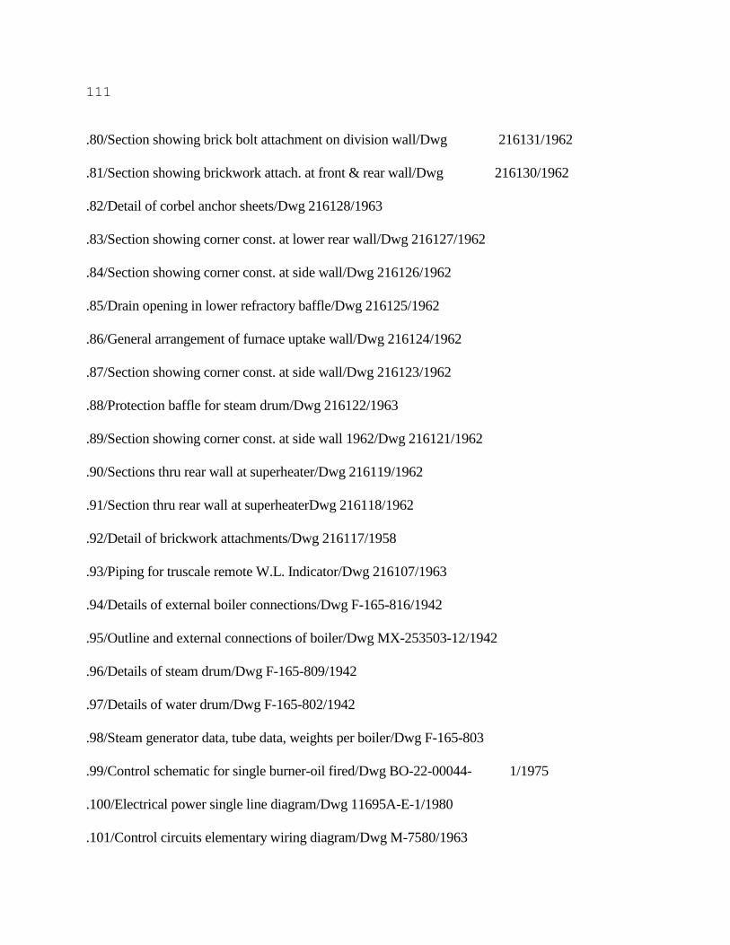
111
.80/Section showing brick bolt attachment on division wall/Dwg 216131/1962
.81/Section showing brickwork attach. at front & rear wall/Dwg 216130/1962
.82/Detail of corbel anchor sheets/Dwg 216128/1963
.83/Section showing corner const. at lower rear wall/Dwg 216127/1962
.84/Section showing corner const. at side wall/Dwg 216126/1962
.85/Drain opening in lower refractory baffle/Dwg 216125/1962
.86/General arrangement of furnace uptake wall/Dwg 216124/1962
.87/Section showing corner const. at side wall/Dwg 216123/1962
.88/Protection baffle for steam drum/Dwg 216122/1963
.89/Section showing corner const. at side wall 1962/Dwg 216121/1962
.90/Sections thru rear wall at superheater/Dwg 216119/1962
.91/Section thru rear wall at superheaterDwg 216118/1962
.92/Detail of brickwork attachments/Dwg 216117/1958
.93/Piping for truscale remote W.L. Indicator/Dwg 216107/1963
.94/Details of external boiler connections/Dwg F-165-816/1942
.95/Outline and external connections of boiler/Dwg MX-253503-12/1942
.96/Details of steam drum/Dwg F-165-809/1942
.97/Details of water drum/Dwg F-165-802/1942
.98/Steam generator data, tube data, weights per boiler/Dwg F-165-803
.99/Control schematic for single burner-oil fired/Dwg BO-22-00044- 1/1975
.100/Electrical power single line diagram/Dwg 11695A-E-1/1980
.101/Control circuits elementary wiring diagram/Dwg M-7580/1963

112
.150/Galley equipment/Dwg 35-H-30/1979
.200/Tunnel ventilation/Dwg 35-H-218/1965
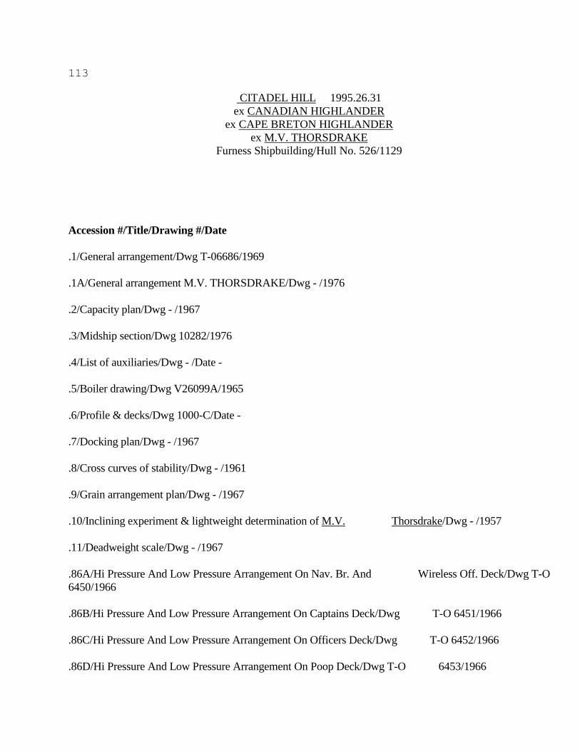
113
CITADEL HILL 1995.26.31
ex CANADIAN HIGHLANDER
ex CAPE BRETON HIGHLANDER
ex M.V. THORSDRAKE
Furness Shipbuilding/Hull No. 526/1129
Accession #/Title/Drawing #/Date
.1/General arrangement/Dwg T-06686/1969
.1A/General arrangement M.V. THORSDRAKE/Dwg - /1976
.2/Capacity plan/Dwg - /1967
.3/Midship section/Dwg 10282/1976
.4/List of auxiliaries/Dwg - /Date -
.5/Boiler drawing/Dwg V26099A/1965
.6/Profile & decks/Dwg 1000-C/Date -
.7/Docking plan/Dwg - /1967
.8/Cross curves of stability/Dwg - /1961
.9/Grain arrangement plan/Dwg - /1967
.10/Inclining experiment & lightweight determination of M.V. Thorsdrake/Dwg - /1957
.11/Deadweight scale/Dwg - /1967
.86A/Hi Pressure And Low Pressure Arrangement On Nav. Br. And Wireless Off. Deck/Dwg T-O
6450/1966
.86B/Hi Pressure And Low Pressure Arrangement On Captains Deck/Dwg T-O 6451/1966
.86C/Hi Pressure And Low Pressure Arrangement On Officers Deck/Dwg T-O 6452/1966
.86D/Hi Pressure And Low Pressure Arrangement On Poop Deck/Dwg T-O 6453/1966
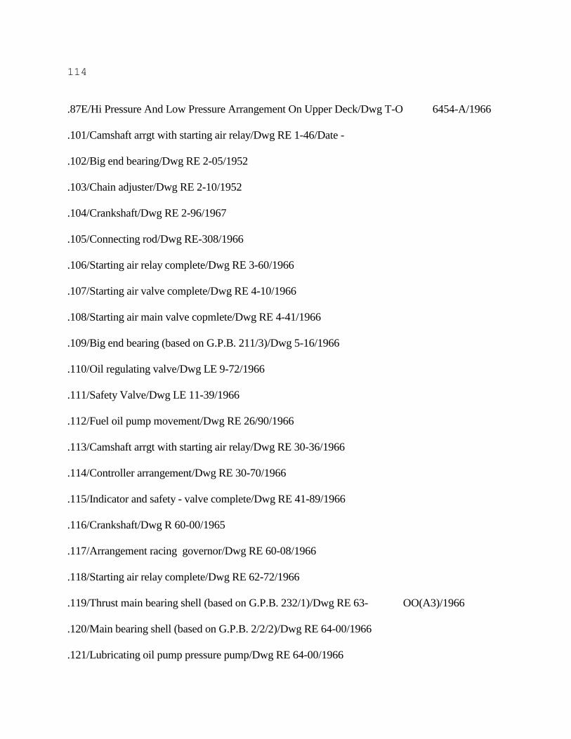
114
.87E/Hi Pressure And Low Pressure Arrangement On Upper Deck/Dwg T-O 6454-A/1966
.101/Camshaft arrgt with starting air relay/Dwg RE 1-46/Date -
.102/Big end bearing/Dwg RE 2-05/1952
.103/Chain adjuster/Dwg RE 2-10/1952
.104/Crankshaft/Dwg RE 2-96/1967
.105/Connecting rod/Dwg RE-308/1966
.106/Starting air relay complete/Dwg RE 3-60/1966
.107/Starting air valve complete/Dwg RE 4-10/1966
.108/Starting air main valve copmlete/Dwg RE 4-41/1966
.109/Big end bearing (based on G.P.B. 211/3)/Dwg 5-16/1966
.110/Oil regulating valve/Dwg LE 9-72/1966
.111/Safety Valve/Dwg LE 11-39/1966
.112/Fuel oil pump movement/Dwg RE 26/90/1966
.113/Camshaft arrgt with starting air relay/Dwg RE 30-36/1966
.114/Controller arrangement/Dwg RE 30-70/1966
.115/Indicator and safety - valve complete/Dwg RE 41-89/1966
.116/Crankshaft/Dwg R 60-00/1965
.117/Arrangement racing governor/Dwg RE 60-08/1966
.118/Starting air relay complete/Dwg RE 62-72/1966
.119/Thrust main bearing shell (based on G.P.B. 232/1)/Dwg RE 63- OO(A3)/1966
.120/Main bearing shell (based on G.P.B. 2/2/2)/Dwg RE 64-00/1966
.121/Lubricating oil pump pressure pump/Dwg RE 64-00/1966
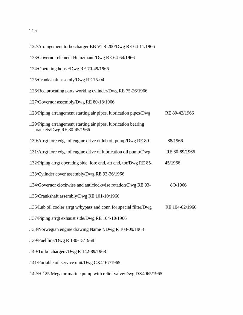
115
.122/Arrangement turbo charger BB VTR 200/Dwg RE 64-11/1966
.123/Governor element Heinzmann/Dwg RE 64-64/1966
.124/Operating house/Dwg RE 70-49/1966
.125/Crankshaft assemly/Dwg RE 75-04
.126/Reciprocating parts working cylinder/Dwg RE 75-26/1966
.127/Governor assembly/Dwg RE 80-18/1966
.128/Piping arrangement starting air pipes, lubrication pipes/Dwg RE 80-42/1966
.129/Piping arrangement starting air pipes, lubrication bearing
brackets/Dwg RE 80-45/1966
.130/Arrgt fore edge of engine drive ot lub oil pump/Dwg RE 80- 88/1966
.131/Arrgt fore edge of engine drive of lubrication oil pump/Dwg RE 80-89/1966
.132/Piping arrgt operating side, fore end, aft end, tor/Dwg RE 85- 45/1966
.133/Cylinder cover assembly/Dwg RE 93-26/1966
.134/Governor clockwise and anticlockwise rotation/Dwg RE 93- 8O/1966
.135/Crankshaft assembly/Dwg RE 101-10/1966
.136/Lub oil cooler arrgt w/bypass and conn for special filter/Dwg RE 104-02/1966
.137/Piping arrgt exhaust side/Dwg RE 104-10/1966
.138/Norwegian engine drawing Name ?/Dwg R 103-09/1968
.139/Fuel line/Dwg R 130-15/1968
.140/Turbo chargers/Dwg R 142-89/1968
.141/Portable oil service unit/Dwg CX4167/1965
.142/H.125 Megator marine pump with relief valve/Dwg DX4065/1965
116
.143/Horizontal watercooled aftercooler - type HE/Dwg KX12449/Date -
.148/Brackets for hatch cleats/Dwg 100027-A/1967
.149/Engine test sheet for bergen diesel/Dwg 137-91/1966
.150/Arrangement of hydraulic jacks/Dwg 114014/Date -
.150A/Arrangement of electric hydraulic steering gear/Dwg A8463/1967
.151/Connecting rod/Dwg D-75740/1976
.152/Main engine bedplate/Dwg - /Date -
.153/Main engine bearings/Dwg - /1976
.153A/Main bearing/Dwg 1414A36/1963
.154/Cross head bearing/Dwg D-76197/1966
.155/Cross head bearing/Dwg 1392A73/1963
.156/Cross head bearing/Dwg 10420-8/1976
.157/Bottom end bearing/Dwg - /1967
.157A/Crankpin bearing/Dwg 1429A61/1963
.158/Electric wiring/Dwg 2513-C/1975
.159/Electrical schematic remote control main engine/Dwg 3195- 6.1a/1973
.160/Electrical schematic remote control main engine/Dwg 3195-6.3/1955
.161/Michell tunnel bearing/Dwg 45304-1/1966
.163/Norwegian diagram Name ? /Dwg 634-6.13/Date -
.163A/Norwegian diagram Name ? /Dwg 634-6.15/1969
.164/Arrgt of Serck drain cooler/Dwg 72101/Date -
.165/Arrgt of Serck oil cooler/Dwg 73855-73856/Date -
117
.165A/Arrgt of Serck oil cooler/Dwg 73895/Date -
.166/Oil cooler/Dwg 73895.B/Date -
.167/Assembly of shaft bonding unit/Dwg 98-133/Date -
.168/Piping schematic main engine console/Dwg 800006-6-7/1966
.169/Schematic diagram of control air system on engine/Dwg 800006- 18-4/1966
.170/Flow sheet for control air on remote control of main engine B & W VT 2 BF/Dwg 9029-
Q3.1/1972
.171/Autochief 1 Wiring diagram/Dwg 9029-Q6.8/1973
.172/Standard oil separator CM-1816 dimensional sketch/Dwg C2-33636/1966
.173/Dimensional sketch CNS 69 Marine/Dwg Cl-33995/1966
.174/Superjector CNS 80/Dwg Cl-33996/1966
.175/Norwegian drawing Name ? /Dwg 1642/1963
.176/Norwegian drawing Name ? /Dwg U4029.1/Date -
118
Citadel Hill 1995.26.32
.200/Feed water filter & float tank/Dwg 25759/1964
.201/Key plan of hopper & double bottom units/Dwg 9621/1967
.201A/Hopper Side And Shell/Dwg 9699/1969
.202/Detail of flush type manhole in tank top/Dwg 9661/1967
.203/Detail of bilge well manholes/Dwg 9663/1967
.203C/Double bottom frs 155 to 197 Unit no. 96 cen.re, 97 stbd,
99 port, 116 centre, 117 stbd, & 118 port/Dwg 9720/Date -
.204/Tank top and inner bottom shell/Dwg 9737/1967
.205/Detail of manhole access to valves in bilge wells/Dwg 9740- C/1967
.206/Cargo hatch stowage arrangement T.S./Dwg 10007-B/1967
.207/Details of access hatches & ladders to cargo holds/Dwg 9745- A/1966
.208/Unit no. 49 stbd, unit no. 50 port, shell & E.R. flat/Dwg 9751-B/1967
.208A/Unit no. 138 centre, unit no. 139 stbd, unit no. 140 port,
W.T. BuIkhead fr 195 /Dwg 9755-E/1969
.210/Unit no. 41, double bottom in engine room (centre) O.T.
bulkheads below upper deck/Dwg 9774-B/1969
.211/Double bottom in engine room/Dwg 9775/1969
.211B/Key plan of upper deck & saddle tank units/Dwg 9657/1969
.212/Overboard discharges/Dwg 9850/1967
.213/Fabricated M.S. bollards (sht 1)/Dwg 9854/1967
.214/Engine room skylight/Dwg T/S-10,132-A/1967
.215/Pedestal fairlead seats (sht 2)/Dwg 9863/1967
.216/Lifting beams in engine room (sht 1)/Dwg 9875/1966

119
.217/Lifting beams in engine room/Dwg 9883/1967
.218/Auxiliary seats (tank top) (sht 1)/Dwg 9908/1966
.218B/Poop deck & side shell/Dwg 9940-B/1969
.219/Fly plan to cargo hatch coamings showing F.B. headers in way of coaming stays/Dwg 9947/1967
.220/Hatch coamings/Dwg 9958-F/1967
.221/Steel door list/Dwg 9988/1967
.222/Bulwark on poop deck in way of deckhouse (sht 2)/Dwg 9989/1967
.223/Seat for purifier operating water tank/Dwg 9992/Date -
.224/Seat for camshaft lub oil tank/Dwg 9994/Date -
.225/Seat for drains cooler/Dwg 9995/Date -
.226/Seats for spare propeller shaft/Dwg 9996/Date -
.227/Seat for piston rod stuffing box drain tank/Dwg 9997/Date -
.228/Seat for bilge & general service pump/Dwg 9998/Date -
.229/Seat for bilge pump/Dwg 9999/Date -
.230/Seat for domestic fresh water & sea water pumps/Dwg 10000/Date -
.231/Seat for E.R. fresh water system/Dwg 10001/Date -
.232/Seat for M.E. lub oil coolers solvent cleaning unit/Dwg 10002/Date -
.233/Seat for feed filter tank/Dwg 10003/Date -
.234/Seat for observation tank/Dwg 10004/Date -
.235/Seat for stbd fire & eductor pump/Dwg 10009/Date -
.236/Seat for diesel alternator sump drain tie/Dwg 10010/Date -
.236A/Seat for sterntube lub oil tank/Dwg 10011/Date -
120
.236B/Seat for domestic refrigeration pumps/Dwg 10012/Date -
.237/Seat for air conditioning pump/Dwg 10013/Date -
.238/Seats for air receivers/Dwg 1003/1967
.239/Seat for oily water separator/Dwg 10039/Date -
.240/Cancelled seat for exhaust valve grinding machine/Dwg 10040/1967
.241/Seat for exhaust valve grinding machine/Dwg 10040-A/1967
.241A/Seat for Cochran boiler/Dwg 10041/Date -
.242/Seats for feed water circulating pumps/Dwg 10042/Date -
.242A/Feed pumps/Dwg - /Date -
.243/Seat for fuel valve spindle oil storage tank/Dwg10043/Date -
.244/Seat for steam drum/Dwg 10044/Date -
.245/Seat for sterntube lub oil header tank/Dwg 10045/Date -
.246/Seat for domestic water pressure tanks/Dwg 10046/Date -
.247/Seat for daily service oil tanks/Dwg 10047/Date -
.248/Seat for deck air compressor/Dwg 1004/Date -
.249/Seat for deck air compressor after cooler/Dwg 10049/Date -
.250/Seat for deck air receiver/Dwg 10050/Date -
.251/Seat for main engine fuel oil return receiver/Dwg 10051/Date -
.252/Seat for H.O. purifiers/Dwg 10052/1967
.253/Seat for pre/heater/Dwg 10053/Date -
.254/Seat for main engine fuel oil circulating pumps/Dwg 10054/Date -
.255/Seat for H.O. fuel purifier heaters/Dwg 10055/Date -
121
.256/Seat for fuel oil purifier electric heater/Dwg 10056/Date -
.257/Seats for main air compressors/Dwg 10057/Date -
.258/Seat for diesel alternator F.W. cooler/Dwg 10058/Date -
.259/Seat for F.W. cooler/Dwg 10059/Date -
.260/Seat for F.W. generator/Dwg 10060/Date -
.261/Seat for lub oil tank purifier/Dwg 10061/Date -
.262/Seat for self cleaning lub oil purifier/Dwg 10062/Date -
.263/Seat for L.O. purifier heater/Dwg 10063/Date -
.264/Seat for electric L.O. heater/Dwg 10064/Date -
.265/Seats for 5 cylinder diesel alternator (port side drawn,
stbd similar)/Dwg 10065/Date -
.267/Lifting beam for spare tail shaft (sht 2)/Dwg 10067/1967
.268/Seat for diesel alternator air compressor/Dwg 10069/Date -
.269/Seat for standby H.O. purifier/Dwg 10070/Date -
.270/Seat for hand operated air compressor/Dwg 10071/Date -
.271/Seats for main engine fuel oil filters/Dwg 10072/Date -
.272/Seat for diesel alternator starting bottle/Dwg 10073/Date -
.273/Seat for air receiver for emergency hand operated compressor/Dwg 10074/Date -
.273A/Seat for F.W. pumps/Dwg 10075/Date -
.274/Seat for sludge pump/Dwg 10081/1967
.274A/Forecastle deck & internal bulkheads/Dwg 10082C/1966
.275/Seat for boiler oil tank/Dwg 10086/1967
122
.276/Seat for main engine F.W. header tank/Dwg 10087/Date -
.277/Support bracket for main engine exhaust pipe 'A'/Dwg 10088/Date -
.278/Support bracket for main engine exhaust pipe 'C'/Dwg 10089/Date -
.279/Anti-roll stays for exhaust gas boiler/Dwg 10090/Date -
.280/Port side trunks ventilators on casing side (sht 1)/Dwg 10096- A/1967
.280A/Port side trunks ventilators on casing side (sht 1)/Dwg 10096/1967
.281/Stbd side vent trunks ventilators on casing side (sht 2)/Dwg 10097/1967
.282/Stbd side vent trunks ventilators on casing side (sht2)/Dwg 10097-A/1967
.283/Arrangement of natural ventilation/Dwg 10127/1967

123
Citadel Hill 1995.26.33
.284/Seat for polytex emergency fire pump in forecastle space/Dwg 10148/1967
.285/Control console/Dwg 10162/1967
.286/Foremast and crows nest/Dwg 10164/1967
.287/Seat for diesel alternators exhaust silencers/Dwg 10170/1967
.288/Seat for oil fired boiler ignition unit/Dwg 10173/1967
.289/Seat for exhaust valve storage tank/Dwg 10174/Date -
.290/Seat for H.W. circulating pump/Dwg 10175/Date -
.290A/Centrifugal pump/Dwg - /1964
.290B/Centrifugal pump C.M.B./Dwg 54241/1971
.291/Arranqement of rudder carrier/Dwg C11757/1967
.292/Sternframe & rudder/Dwg B.147/1965
.293/Midship deckhouse/Dwg 10193/1967
.294/Shell expansion/Dwg 9603-E/1967
.295/Aft end construction/Dwg 1015-F/1965
.296/Fore end construction/Dwg 1019-C/1966
.301/Diagrammatic Arrangement of bilge system/Dwg 6113-D/1966
.302/Diagrammatic arrangement of ballast system/Dwg 6114-D/1966
.302A/Diagrammatic arrangement of bilge & ballast system
(in way of cargo hold)/Dwg E.38.A/1966
.303/Diagrammatic arrangement of sea water system/Dwg 6115-D/1965
.304/Diagrammatic arrangement of fresh water pipes/Dwg 6116-C/1966
.305/Diagrammatic arrangement of O.F. suction & discharge mains
124
& transfer pump suctions/Dwg 6117-B/1965
.305A/Diagrammatic arrangement of O.F. suction & discharge mains
& transfer pump suctions/Dwg 6117-C/1965
.306/Diagrammatic arrangemnet of O.F. discharges purifier
system, etc./Dwg 6118-E/1965
.307/Diagrammatic arrangement of lubricating oil pipes/Dwg 6119- A/1966
.308/Diagrammatic arrangement of lubricating oil pipes/Dwg 6119- F/1966
.309/Diagrammatic arrangement of lubricating oil pipes/Dwg 6119- G/1966
See Instruction Manuals
.310/Diagrammatic arrangement of feed & blowdown pipes/Dwg 6120- A/1966
.311/Diagrammatic arrangernent of feed & blowdown pipes/Dwg 6120- B/1966
.312/Diagrammatic arrangement of steam pipes/Dwg 6121-A/1966
.313/Diagrammatic arrangement of steam pipes/Dwg 6121-E/1966
.314/Diagrammatic arrangement of exhaust pipes/Dwg 6122-E/1966
.314A/Arrangement & details of shafting/Dwg 6146-D/1965
.315/Arrangement & details of sterntube/Dwg 6166/1966
.315A/Arrangement of compressed air pipes (sht 1)/Dwg 6171-C/1967
.315B/Arrangement of compressed air pipes (sht 2)/Dwg 6171-C/1967
.316/Arrangement of compressed air pipes (sht 3)/Dwg 6171-C/1967
.316A/Arrangement of compressed air pipes (sht 4)/Dwg 6171-C/1967
.317/Arrangement of prop shaft withdrawal/Dwg 6184-A/1966

125
Citadel Hill 1995.26.34
.318/Underfloor pipe arrangement (sht 1)/Dwg 6209-D/1966
.319/Underfloor pipe arrangement (sht 2)/Dwg 6209-D/1966
.320/Underfloor pipe arrangement (sht 1)/Dwg 6209-E/1966
.321/Underfloor pipe arrangement (sht 2)/Dwg 6209-E/1966
.321A/Lub & fuel oil pipe arrangement (sht 1)/Dwg 6232-C/1967
.321C/Lub & fuel oil pipe arrangement (sht 3)/Dwg 6232-C/1967
.322/Lub & fuel oil pipe arrangement (sht 4)/Dwg 6232-C/1967
.323/Main engine console instruments/Dwg 6233-A/1967
.324/Water discharges pipe arrangement (sht 1)/Dwg 6239-C/1966
.325/Water discharges pipe arrangement (sht 2)/Dwg 6239-C/1966
.325B/Water discharges pipe arrangement (sht 3)/Dwg 6239-E/1966
.325C/Water discharges pipe arrangement (sht 4)/Dwg 6239-E/1966
See/Instruction Manuals - 2
.326/Water discharges pipe arrangement (sht 5)/Dwg 6239-E/1966
.327/Arrangement & details of funnel unit no. 165/Dwg 6251-A/1966
.328/Arrangement of feed steam & exhaust pipes (sht 3)/Dwg 6270- A/1967
.328B/Arrangement of feed steam & exhaust pipes (sht 1)/Dwg 6270- B/1967
.328C/Arrangement of feed steam & exhaust pipes (sht 2)/Dwg 6270- B/1967
.329/Arrangement of feed steam & exhaust pipes (sht 3)/Dwg 6270- B/1967
.329A/Arrangement of feed steam & exhaust pipes (sht 4)/Dwg 6270- B/1967

126
Citadel Hill 1995.26.35
.33O/Machinery arrangement (sht 1)/Dwg 6284-A/1967
.330A/Machinery arrangement (sht 2)/Dwg 6284-A/1967
.330B/Machinery arrangement (sht 3)/Dwg 6284-A/1967
.331/Auxiliary machinery arrangement/Dwg - /Date -
.331A/Heating coils in double bottom tanks (sht 2)/Dwg 6320-B/1966
.332/Accomodation (sht 1)/Dwg 6373-D/1966
.333/Accomodation (sht 1)/Dwg 6373-F/1965
.334/Accomodation (sht 2)/Dwg 6374-G/1965
.335/Diagrammatic arrangement of 0.F. suction & discharge mains
& transfer pump suctions/Dwg 6376-E/1965
.336/Diagrammatic arrangement of 0.F. discharges purifier system, etc./Dwg 6404-G/1965
.337/Diagrammatic arrangement of steam pipes/Dwg 6405-F/1966
.338/Diagrammatic arrangement of exhaust pipes/Dwg 6406-F/1966
.339/Steam chamber arrangement of pipe connections/Dwg P-326- 667/1965
.340/Connection for exhaust boilers/Dwg P-326-679/1965
.341/Refrigerated chambers/Dwg 6423-B/1966
.342/Fire/washdeck line/Dwg 6434-A/1966
.343/Fire fighting equipment plan/Dwg 6481.A/1967
127
Citadel Hill 1995.26.36
.351/Hold bulkhead/Dwg 988-8/1965
.352/Garage for a crane car/Dwg 5322.001.A/1972
.353/Mountings arrangement/Dwg T.26255.A/1965
.354/Electric torsionmeter 19"-22" general arrangement/Dwg M1035AQ/1956
.355/BT5 Compressor arrangement 2 with NEBB. 0MQA84 electric motor/Dwg BBT5-101/1966
.356/Norus cleaning plan/Dwg N-2-lOR/1966
.357/Standard air receivers/Dwg 97002837/1960
.358/Detail & arrangement of air receiver/Dwg Tl-12531/1966
.400/Wiring diagram of talkback amplifier & relay panel/Dwg 11229- E-l/1979
.401/Interior communication system block diagram/Dwg11229-E-2/1979
.402/I.C. system - horn box/Dwg 11229-E-SK-l/1979
.403/I.C. system -relay box/Dwg 11229-E-SK-2/1979
.404/I.C. system - talkback speaker type 1/Dwg 11229-E-SK-3/1979
.405/I.C. system - talkback speaker type 2/Dwg 11229-E-SK-4/1979
.406/Connection diagram of telephone exchanger & talkback
amplifier rack/Dwg 11229-E-SK-5/1979
.407/Connection diagram of J.B./Dwg 11229-E-SK-6/1979
.408/Connection diagram of J.B./Dwg 11229-E-SK-7/1979
.409/Connection diagram of J.B./Dwg 11229-E-SK-8/1979
.410/Connection diagram of J.B./Dwg 11229-E-SK-9/1979
.411/Connection diagram of J.B./Dwg 11229-E-SK-10/1979
.412/Connection diagram of J.B./Dwg 11229-E-SK-ll/1979

128
.413/Connection diagram of desk type telephone/Dwg 11229-E-SK- 12/1979
.414/Connection diagram of wall type telephone/Dwg 11229-E-SK- 13/1979
.415/Connection diagram of sound powered telephone/Dwg 11229-E-SK- 14/1979
.415A/Sypertyfon air whistle Drawings No. 502/615/600/727/751;
TY 617/1954
.416/Schematic & connection diagram of talkback master station/Dwg 11229-E-SK-15/1979
.416A/Single line diagram for switch boards/Dwg E.4428/1967
.416B/Arrangement of electric lighting (sht 1)/Dwg E.4494/1965
.416C/Arrangement of electric lighting (sht 2)/Dwg E.4494/1965
.417/Propellor/Dwg 12238 S-2/1965
.418/Propellor/Dwg 122378 S-2/1965
.451/Hatch cover parking ramp hatch no. 1 assembly & details/Dwg 128410-0/1966
.452/Crankshaft/Dwg 145446/1967
.453/Crankshaft approval drawing/Dwg 145531/1965
.454/Crankshaft arrangement/Dwg 20-10200/1966
.454A/Crankshaft deflection/Dwg 98166/1962
.455/Arrangement of piston cooling/Dwg 1455A25/1963
.456/Section of engine/Dwg 145566/1967
.457/Cylinder lubricator piping/Dwg 145629/1964
.458/Marine auxiliary installation details/Dwg 145815/1963
.459/Piston/Dwg 146351/1967
.460/Pipe arrangement (front)/Dwg 146647/1967
129
.461/Pipe arrangement (back)/Dwg 146648/1967
.462/Pipe arrangement (plan)/Dwg 146649/1967
.462A/List for pipe arrangement lub oil system/Dwg 146650/1965
.462B/List for pipe arrangement piston cooling oiI drains &
turbo-blower lub oil system/Dwg 146650/1965
.462C/List for pipe arrangement piston cooling system/Dwg 146650/1965
.462D/List for pipe arrangement steam system/Dwg 146650/1965
.462E/List for pipe arrangement turbo-blower lub oil system & drains/Dwg 146650/1965
.462F/List for pipe arrangement starting air system/Dwg 146650/1965
.462G/List for pipe arrangement cooling water system/Dwg 146650/1965
.462H/List for pipe arrangement fuel oil system/Dwg 146650/1965
.462I/List for pipe arrangement fuel oil system & fuel valve
cooling system/Dwg 146650/1965
.462J/List for pipe arrangement fuel valve cooling system/Dwg 146650/1965
.462K/List for pipe arrangement fuel oil system & fuel oil drains/Dwg 146650/1965
.462L/List for pipe arrangement fuel oil drains/Dwg 146650/1965
.462M/List for pipe arrangement lub oil drains/Dwg 146650/1965
.462N/List for pipe arrangement thermometers & pressure gauges/Dwg 146650/1965
.462O/List for pipe arrangement piston cooling & lub oil drains 146650/1965
.462P/List for pipe arrangement piston cooling oil drains/Dwg 146650/1965
.462Q/List for pipe arrangement pressure gauges/Dwg 146650/1965
.463/Fuel pump arrangement (lower part)/Dwg 147041/1966
.464/Arrangement of manoeuvring gear/Dwg 147231/1966

130
.465/Exhaust valve spindle guide/Dwg 147334/1964
.465A/Fuel valve assembly/Dwg 147411/1966
.466/Exhaust valve assembly/Dwg 147505/1964
.467/Fuel pump arrangement (upper)/Dwg 147523/1965
.468/Diesel engine standard 8feed cylinder lubricator (Manzel
'B' type - auto filling with separate float tank)/Dwg 147805/1966
.469/Diesel engine standard 8feed cylinder lubricator (Manzel
'B' type - auto filling with separate float tank)/Dwg147806
.469A/Norwegian Drawing (?)/Dwg 148711-2/1969
.469B/Hatch covers mounting of support brackets/Dwg 156044-2/1970
.470/Adjustments for fuel regulation/Dwg 1529A75/1964
.471/Chain drive & lubrication arrangement/Dwg 1570A37/1964
.472/Exhaust cam/Dwg 1574B71/1965
.473/Arrangement for C02 slunking/Dwg 1590B74/1965
.473A/C02 pipe arrangement/Dwg E-373/1966
.474/Norwegian engine drawing name (?)/Dwg 1788C92/1967
.475/Control arrangement/Dwg 1813B55/1967
.476/Norwegian engine drawing name (?)/Dwg 183215/Date -
.477/Scavenge doors/Dwg 1674B71/1966
.478/Shafting/Dwg 191389/1968
.479/Shims between cooling jacket & scavenging box/Dwg 191535/1968
.480/Norwegian drawing name (?)/Dwg 191576/1969
.481/Norwegian drawing name (?)/Dwg 191577/1969
.482/Norwegian drawing name (?)/Dwg 191578/1969
131
.482A/Norwegian drawing name (?)/Dwg 222168/1967
.483/Norwegian drawing name (?)/Dwg 222173/1967
.484/Norwegian drawing name (?)/Dwg 223803/Date -
.485/Measured clearance in assemblings/Dwg 223804/1968
.486/Fitting of clock gauge on scavenging box/Dwg 223995/1968
.501/Unloading control booth/Dwg 100-001/1979
.502/Keyplan of doors & door schedule/Dwg 102-001 1/1979
.503/Details of tunnel walkway - mech. ventilation air intake
cowl/Dwg 115-001 3/1979
.504/ A/C unit for unloading control booth/Dwg 115-002 1/1979
.505/Nameplates/Dwg 123-001 0/1979
.506/Boom support & rigging arrangement & details/Dwg 202-001 1/1979
.507/Boom support & rigging arrangement & details/Dwg 202-001 2/1979
132
Citadel Hill 1995.26.37
.508/Watertight doors details (sht 1)/Dwg 301-001/1979
.509/Watertight doors details (sht 1)/Dwg 301-001 1/1979
.510/Small hatches & manholes/Dwg 302-001 0/1979
.511/Loop belt casing ladder arrangement/Dwg 305-001 0/1979
.512/Loop belt casing ladder arrangement (sht 1)/Dwg 305-001 2/1979
.513/Drive motor platform ladder & gratings (sht 1)/Dwg 305-001 3/1979
.514/Drive motor platform ladder & gratings (sht 2)/Dwg 305-001 0/1979
.515/Loop belt take-up pump seat arrangement (sht 3)/Dwg 305- 0010/1980
.516/Loop belt casing ladder details/Dwg 305-002 1/1979
.517/Detail forward vent trunk ladder (sht 1)/Dwg 305-003 0/1979
.518/Access ladder for P & S take-up trunks, no. 8 hold & aft
void spaces (sht 2)/Dwg 305-003 0/1979
.519/Keyplan of ladders/Dwg 305-004 1/1979
.520/Painting schedule/Dwg 315-001 5/1979
.521/Piping list for SW cooling system vacuum priming system &
air starting system for unloading generators (sht 1)/Dwg 500- 002/1979
.522/Pipe list for tunnel wash down system/Dwg 500-002/1979
.523/Pipe list for tunnel compressed air/Dwg 500-002/1979
.524/Pipe list for slurry piping system (sht 2)/Dwg 500-002/1979
.525/Engine room - composite arrangement/Dwg 500-0041/1979
.526/Unloading generator room - composite arrangement/Dwg 500-004 1/1979
.527/Tank composite arrangement/Dwg 500-005 2/1979
133
.528/Modification to air & sound pipes no. 3 - 2 & 1 centre tanks P & S (sht 1)/Dwg 500-005 0/1979
.529/Upper deck - composite arrangement/Dwg 500-006 0/1979
.530/Tunnel gate system for conveyor location & detail of brackets/Dwg 500-007 0/1979
.531/Tunnel gate SVS hyd piping arrangement/Dwg 500-008 0/1979
.532/Valve nameplate list - system: slurry & ballast & vacuum
priming; cooling water; fuel oil; compressed air; diesel
exhaust (shts l; 122; 3; 4; & 5)/Dwg 517-001/1979
.533/Bow thruster composite/Dwg 600-005 2/1979
.534/Spare parts list/Dwg 630-001 0/Date -
.535/Lubricants & hydraulic oils list/Dwg 633-01 0/1979
.536/Lubricants & hydraulic oils list/Dwg 633-01 1/1979
.537/Bow thruster connection diagram/Dwg 700-001 1/1979
.538/wireway to boom/Dwg 701-001/1979
.539/Wireway's port & stbd tunnels/Dwg 701-002/1979
.540/Wireway's port & stbd tunnels/Dwg 701-002 1/1979
.541/Unloading switchboard & M.C.C. cable transits, section
"A" & "AR" (sht 1)/Dwg 701-003/Date -
.542/Unloading switchboard & M.C.C. cable transits, section
"BF" & "BR" (sht 122)/Dwg 701-003/Date -
.543/Unloading switchboard & M.C.C. cable transits, section
"CF" (sht 123)/Dwg 701-003/Date -
.544/Unloading switchboard & M.C.C. cable transits, section
"DF" (sht 124)/Dwg 701-003/Date -
.545/Unloading switchboard & M.C.C. cable transits, section
"EF" (sht 125)/Dwg 701-003/Date -
.546/Unloading switchboard & M.C.C. cable transits, section
134
"FF" (sht 126)/Dwg 701-003/Date -
.547/Unloading switchboard & M.C.C. cable transits, section
"GF" (sht 127)/Dwg 701-003/Date -
.548/Unloading switchboard & M.C.C. cable transits, section
"HF" & "HR" (sht 128)/Dwg 701-003/Date -
.549/Unloading switchboard & M.C.C. cable transits, section
"JF" & "JR" (sht 9)/Dwg 701-003/Date -
.550/Unloading control room (sht 10)/Dwg 701-003/Date -
.551/Unloading control room (sht 11)/Dwg 701-003/Date -
.552/Cable transits at bulkhead 212 (sht 12)/Dwg 701-003/Date -
.553/Cable transits at bulkhead 212 forward (sht 13)/Dwg 701- 003/Date -
.554/Cable transits at bulkhead 212 aft (sht 14)/Dwg 701-003/Date -
.555/Cable transits at bulkhead 212 aft (sht 15)/Dwg 701-003/Date -
.556/Cable transits at generator #1 (sht 16)/Dwg 701-003/Date -
.557/Cable transits at generator #2 (sht 17)/Dwg 701-003/Date -
.558/Cable transits bridge front (sht 18)/Dwg 701-003/Date -
.559/Cable transits tunnel apex fr 128 (port) (sht 19)/Dwg 701- 003/Date -
.560/Cable transits tunnel apex fr 128 (stbd) (sht 20)/Dwg 701- 003/Date -
.561/Cable transits tunnel apex fr 128 (stbd) (sht 21)/Dwg 701- 003/Date -
.562/Cable schedule/Dwg 702-001/1979
.563/Lighting panel (sht 1)/Dwg 703-001/1979
.564/Lighting panel (sht 2)/Dwg 703-001/1979
.565/ 460 Volt distribution panel (sht 3)/Dwg 703-001/1979
.566/Boom lighting panel (sht 4)/Dwg 703-001/1979
135
.567/Arrangement of circuits miscellaneous panel LP4 (sht 5)/Dwg 703-001/1979
.568/ 440 Volt distribution panel (sht 6)/Dwg 703-001/1979
.569/Arrangement of lighting fittings & recepticals on boom
structure/Dwg 710-001 2/1979
.570/Unloading control booth (lighting receptacle arrangement)/Dwg 710-002 1/1979
.571/Lighting conveyor loop/Dwg 710-003 1/1979
.572/Unloading generator room (lighting receptacle arrangement)/Dwg 710-004 1/1979
.573/Lighting port & starboard tunnels/Dwg 710-005 2/1979
.574/Bow thruster compartment lighting/Dwg 710-006 0/1974
.572/Unloading console cabling diagram/Dwg 712-001 0/1979
.573/J.B.-l Junction box connection diagram (sht 1)/Dwg 712-001 1/1979
.573/J.B.-2 Junction box connection diagram (sht 2)/Dwg 712-002 1/1979
.574/J.B.-3 Junction box connection diagram (sht 3)/Dwg 712-002 1/1979
.575/J.B.-4 Junction box connection diagram (sht 4)/Dwg 712-002 1/1979
.576/J.B.-5 Junction box connection diagram (sht 5)/Dwg 712-002 1/1997
.577/J.B.-6 Junction box connection diagram (sht 6)/Dwg 712-002 1/1979
.578/J.B.-7 Junction box connection diagram (sht 7)/Dwg 712-002 1/1979
.579/J.B.-8 Junction box connection diagram (sht 8)/Dwg 712-002 1/1979
.580/J.B.-9 Junction box connection diagram (sht 9)/Dwg 712-002 1/1979
.581/J.B.-10 Junction box connection diagram (sht 10)/Dwg 712- 002 1/1979
.582/Unloading control console terminal bar connection (sht 1)/Dwg 712-003 1/1979
.583/Unloading control console terminal bar connection (sht 2)/Dwg 712-003 1/1979
136
.584/Unloading control console terminal bar connection (sht 3)/Dwg 712-003 1/1979
.585/Unloading control console terminal bar connection (sht 4)/Dwg 712-003 1/1979
.586/Unloading control console terminal bar connection (sht 5)/Dwg 712-003 1/1979
.587/Unloading control console terminal bar connection (sht 6)/Dwg 712-003 1/1979
.588/Unloading control console terminal bar connection (sht 7)/Dwg 712-003 0/1979
.589/Unloading system block cabling diagram (sht 1)/Dwg 712-004 1/1979
.590/Location of unloading control equipment/Dwg 712-006 1/1979
.591/Boom electrical equipment block wiring diagram/Dwg 712-008 0/1979
.592/Fixed structure junction boxes (sht 1)/Dwg 712-009 0/1979
.593/Fixed structure junction boxes connection diagram (sht 2)/Dwg 712-009 0/1979
.593A/Remote alarm panel & generator connections (sht 2)/Dwg 712- 012 0/1980
.594/Fresh & SW cooling-air starting D0 service, F0 filling-mod
to comp air-diesel exhaust & crankcase vent, etc./Dwg 903-001 0/1979
.595/Unloading system - hydraulic diagram/Dwg 903-002 0/1979
.596/Hopper divisions, sides & shedders no. 2 hold (sht 1)/Dwg 907- 002 0/1979
.597/Hopper divisions, sides & shedders no. 2 hold (sht 2)/Dwg 907- 002 0/1979
.598/Details of flush W.T. & 0.T. manholes/Dwg HD-2BBC/1979

137
Frank A. Sherman 1995.26.38
Port Weller/Hull 25/1958
Accession #/Title/Drawing #/Date
.1/General Arrangement/Dwg 25-H-17/1958
138
Goderich 1995.26.38
ex Pathfinder
Detroit Shipbuilding/Hull 66/1906
Accession #/Title/Drawing #/Date
.1/Hydrostatics/dwg - /1968
.2/Shell expansion/dwg 9/1906
.2A/Shell expansion/dwg 66-H-2/1906
.3/Midship section/dwg 3/1905
.4/Ventilation details/dwg 66-H-73/1956
.5/Detail of coal bunker slope plates/dwg 5/1949
.5A/Detail of coal bunker slope plates/dwg 6/1949
.6/ 9 Ton Day bunkers/dwg 3/1949
.7/Coal bunker alterations/dwg 7/1949
.7A/Coal bunker alterations/dwg A/1949
.7B/Bunker alterations/dwg 1/1949
.8/After coal bunker blkhd/dwg 2/1949
.8A/Bulkhead No. 190/dwg 14-317/1905
.9/Boiler room floor/dwg 12-6-1646/1946
.10/Boiler room grating & stairs/dwg 12-4-1646/1946
.11/Mooring winch/dwg E810-1A/1937
.12/Mates pump 7 x 4.5 x 10/dwg 3920/1951
.13/ #9 Redler conveyor details/dwg 4/1949
.14/Conveyor drive detail/dwg 10/1949
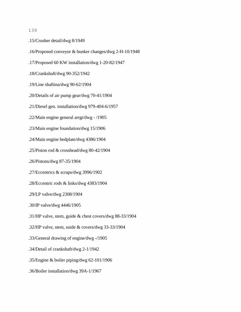
139
.15/Crusher detail/dwg 8/1949
.16/Proposed conveyor & bunker changes/dwg 2-H-10/1948
.17/Proposed 60 KW installation/dwg 1-20-82/1947
.18/Crankshaft/dwg 90-352/1942
.19/Line shaftina/dwg 90-62/1904
.20/Details of air pump gear/dwg 70-41/1904
.21/Diesel gen. installation/dwg 979-404-6/1957
.22/Main engine general arrgt/dwg - /1905
.23/Main engine foundation/dwg 15/1906
.24/Main engine bedplate/dwg 4386/1904
.25/Piston rod & crosshead/dwg 80-42/1904
.26/Pistons/dwg 87-35/1904
.27/Eccentrics & scraps/dwg 3996/1902
.28/Eccentric rods & links/dwg 4383/1904
.29/LP vaIve/dwg 2308/1904
.30/IP valve/dwg 4446/1905
.31/HP valve, stem, guide & chest covers/dwg 88-33/1904
.32/HP valve, stem, suide & covers/dwg 33-33/1904
.33/General drawing of engine/dwg -/1905
.34/Detail of crankshaft/dwg 2-1/1942
.35/Engine & boiler piping/dwg 62-101/1906
.36/Boiler installation/dwg 39A-1/1967

140
.37/Boilers/dwg E-902/1940
.37A/Main boilers/dwg 10-1-1624/1939
.38/Steam piping - profile (sht 1)/dwg 13-1-1646/1946
.39/Main steam pipe (sht 2)/dwg 13-2-1646/1946
.39C/Steam piping - section (sht 5)/dwg 13-1-1646/1941
.40/Main steam supports/dwg 13-16-1625
.41/Steam piping plan (sht 3)/dwg 13-1-1646/1941
.41A/Steam piping section (sht 5)/dwg 13-1-1646/1941
.42/Water piping section (sht 6)/dwg 13-1-1646/1941
.42A/Water piping plan (sht 4)/dwg 13-1-1646/1941
.42B/Water piping profile (sht 2 )/dwg 13-1-1646/1941
.43/Feed & filter tank/dwg 133-465/1947
.43A/Feed & fiIter tank, float operating gear/dwg 133-466/1947
.44/Throttle/dwg 6-6/1941
.45/ 8" Throttle flange/dwg 6-6/1941
.46/ 6" Main stop valve/dwg 11-6-1119/1925
.47/ 3" x H Cast steel heater bypass/dwg 19/1939
.48/ 2" x H Cast steel check valve boiler feed/dwg 11-12-1625/1939
.49/Detail of stool for twin safety valves/dwg 13-2/1939
.50/ 2" x H Cast steel boiler feed stop/dwg 11-12-1625/1939
.51/Special tee - 8" x 6" x 6" for main steam line/dwg 13-2-1625/1940
.52/Specifications 80 KW, 120 Volt, DC dead-front switchboard/dwg - /1947
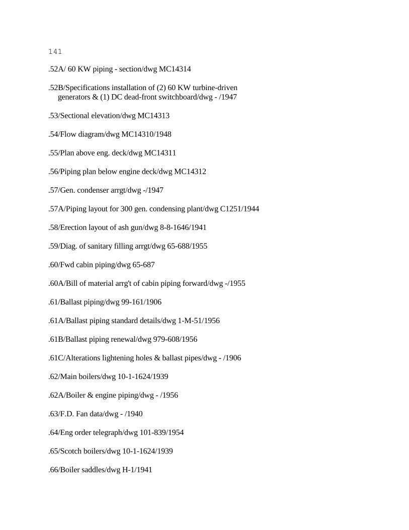
141
.52A/ 60 KW piping - section/dwg MC14314
.52B/Specifications installation of (2) 60 KW turbine-driven
generators & (1) DC dead-front switchboard/dwg - /1947
.53/Sectional elevation/dwg MC14313
.54/Flow diagram/dwg MC14310/1948
.55/Plan above eng. deck/dwg MC14311
.56/Piping plan below engine deck/dwg MC14312
.57/Gen. condenser arrgt/dwg -/1947
.57A/Piping layout for 300 gen. condensing plant/dwg C1251/1944
.58/Erection layout of ash gun/dwg 8-8-1646/1941
.59/Diag. of sanitary filling arrgt/dwg 65-688/1955
.60/Fwd cabin piping/dwg 65-687
.60A/Bill of material arrg't of cabin piping forward/dwg -/1955
.61/Ballast piping/dwg 99-161/1906
.61A/Ballast piping standard details/dwg 1-M-51/1956
.61B/Ballast piping renewal/dwg 979-608/1956
.61C/Alterations lightening holes & ballast pipes/dwg - /1906
.62/Main boilers/dwg 10-1-1624/1939
.62A/Boiler & engine piping/dwg - /1956
.63/F.D. Fan data/dwg - /1940
.64/Eng order telegraph/dwg 101-839/1954
.65/Scotch boilers/dwg 10-1-1624/1939
.66/Boiler saddles/dwg H-1/1941
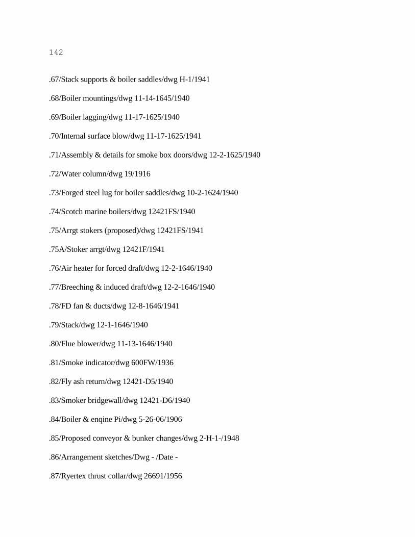
142
.67/Stack supports & boiler saddles/dwg H-1/1941
.68/Boiler mountings/dwg 11-14-1645/1940
.69/Boiler lagging/dwg 11-17-1625/1940
.70/Internal surface blow/dwg 11-17-1625/1941
.71/Assembly & details for smoke box doors/dwg 12-2-1625/1940
.72/Water column/dwg 19/1916
.73/Forged steel lug for boiler saddles/dwg 10-2-1624/1940
.74/Scotch marine boilers/dwg 12421FS/1940
.75/Arrgt stokers (proposed)/dwg 12421FS/1941
.75A/Stoker arrgt/dwg 12421F/1941
.76/Air heater for forced draft/dwg 12-2-1646/1940
.77/Breeching & induced draft/dwg 12-2-1646/1940
.78/FD fan & ducts/dwg 12-8-1646/1941
.79/Stack/dwg 12-1-1646/1940
.80/Flue blower/dwg 11-13-1646/1940
.81/Smoke indicator/dwg 600FW/1936
.82/Fly ash return/dwg 12421-D5/1940
.83/Smoker bridgewall/dwg 12421-D6/1940
.84/Boiler & enqine Pi/dwg 5-26-06/1906
.85/Proposed conveyor & bunker changes/dwg 2-H-1-/1948
.86/Arrangement sketches/Dwg - /Date -
.87/Ryertex thrust collar/dwg 26691/1956
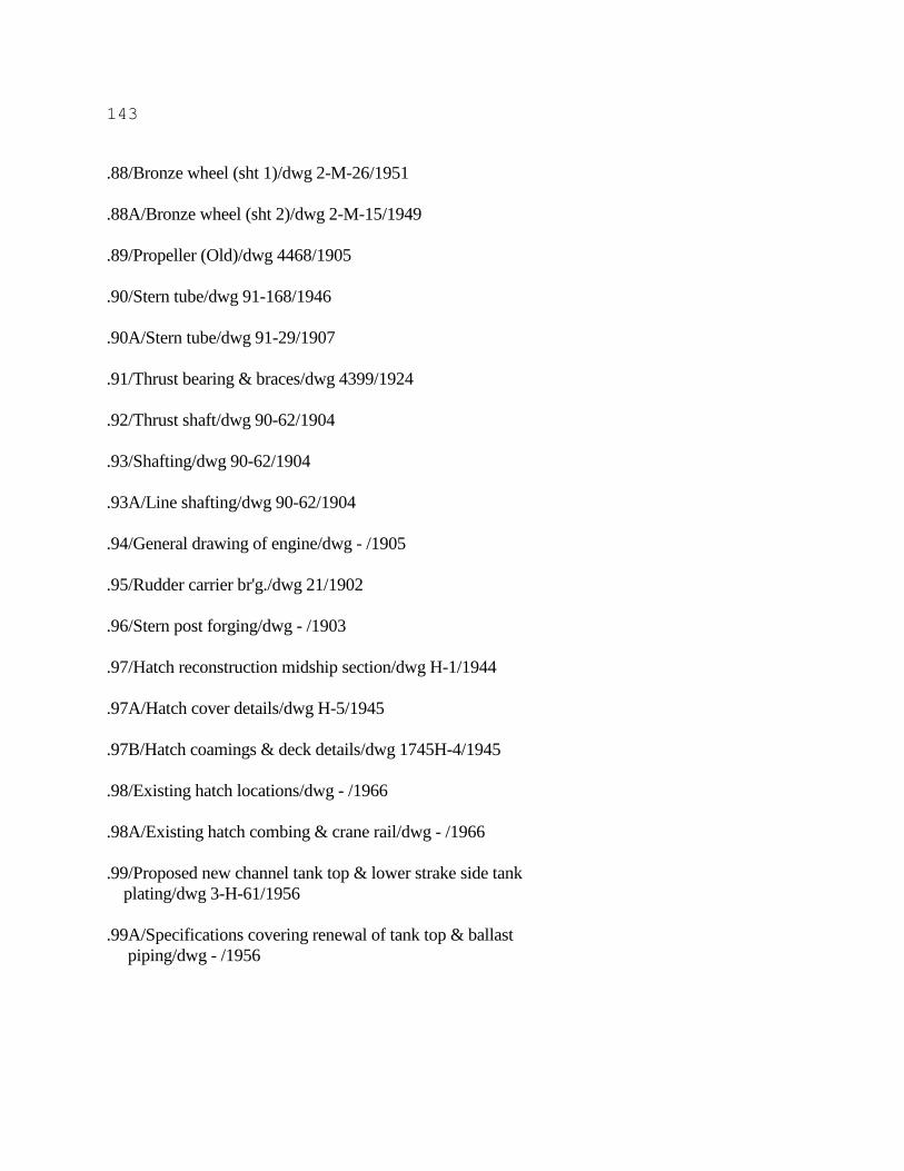
143
.88/Bronze wheel (sht 1)/dwg 2-M-26/1951
.88A/Bronze wheel (sht 2)/dwg 2-M-15/1949
.89/Propeller (Old)/dwg 4468/1905
.90/Stern tube/dwg 91-168/1946
.90A/Stern tube/dwg 91-29/1907
.91/Thrust bearing & braces/dwg 4399/1924
.92/Thrust shaft/dwg 90-62/1904
.93/Shafting/dwg 90-62/1904
.93A/Line shafting/dwg 90-62/1904
.94/General drawing of engine/dwg - /1905
.95/Rudder carrier br'g./dwg 21/1902
.96/Stern post forging/dwg - /1903
.97/Hatch reconstruction midship section/dwg H-1/1944
.97A/Hatch cover details/dwg H-5/1945
.97B/Hatch coamings & deck details/dwg 1745H-4/1945
.98/Existing hatch locations/dwg - /1966
.98A/Existing hatch combing & crane rail/dwg - /1966
.99/Proposed new channel tank top & lower strake side tank
plating/dwg 3-H-61/1956
.99A/Specifications covering renewal of tank top & ballast
piping/dwg - /1956
144
Goderich 1995.25.39
Detroit Shipbuilding/Hull 66/1948
Accession #/Title/Drawing #/Date
.100/Aft cabin steel plan/Dwg 2/1948
.100A/Specifications covering reconstruction of aft cabins, coal
bunker alterations, & relocation of coal handling equip./Dwg - /1948
.100B/Reconstruction of after cabins/Dwg 1/1948
.101/Detail of ordinary frame/Dwg - /Date -
.102/Crew quarters aft/Dwg - /Date 1948
.103/Aft accommodation/Dwg - /1966
.103A/Proposed aft cabin arrgt./Dwg 2-H-9/1948
.104/Tank top & hopper side/Dwg 8/1906
.105/Bulkheads transom & floors for'd/Dwg 12/1906
.106/Specifications for reconstruction of for'd cabins/Dwg - /1955- 1956
.106A/Reconstruction for'd quarters/Dwg 3-H-57/1955
.107/New fuel oil tanks in existing coal bunker space/Dwg - /1972
.108/Screen bhds at frs 57, 89 & 121/Dwg H-2/1945
.109/Steel doors - foc'sle blkhd/Dwg - /1937
.110/Profile & deck plans/Dwg 10/1906
.111/Steel plan dunnage deck/Dwg D165HS1162/1955
.111A/Steel bulkhds on dunnage deck/Dwg D165HS1151/1955
.111B/Arrgt - Dunnage deck/Dwg D165HS3314/Date -
.112/Arrgt New pilot house/Dwg D165HS3311/1955
145
.113/Steel plan deck house for'd/Dwg D165HS1171/1955
.114/Steel plan foc'sle deck/Dwg D165HS1163/1955
.115/Arrangement new pilot house/Dwg D165HS3311/1955
.116/Steel plan pilot house/Dwg D165HS1172/1965
.117/Arrgt spar deck for'd/Dwg D165HS3313/Date -
.118/Arrgt foc'sle deck for'd/Dwg D165HS3312/Date -
.119/Paint schedule/Dwg D165HS1401/Date -
.120/Deck covering/Dwg D165HS1401/1956
.121/Label plates/Dwg D165HS2801/1956
.122/Airport & berth curtains/Dwg D165HS3361/1956
.123/Airport casing details/Dwg D165HS3913/1955
.124/Pilothouse window covers/Dwg 165HS1231003/1955
.124A/Pilothouse windows crank operated/Dwg KS2981/1951
.124B/Pilothouse window fixed/Dwg D165HS1231002/1955
.124C/Pilothouse window spring balanced/Dwg D165HS1231001/1955
.125/ 25" x 25" Weathertight access door/Dwg G438HS1621011A/Date -
.126/Non weathertight door/Dwg D165HS163101/1951
.127/Wardrobe locker details/Dwg D165HS3912/1955
.128/Bathroom supply cabinet/Dwg D165HS361102/1956
.129/Typical joiner details/Dwg D165HS3911/1955
.130/Outside stairs & railings/Dwg D165HS1641B/1955
.131/Inside stairs, gratings, & railings/Dwg D165HS1642A/1956
146
.132/New foremast/Dwg D165HS1721A/1956
.133/Bow roller chock/Dwg D165HS1119/1953
.133A/ 5250 Gallon potable water tank/Dwg D165HS363103/1953
.134/Rain visor/Dwg 165HS1231/1956
.135/Steel bhds spar dk for'd/Dwg D165HS1152A/1955
.135A/Steel plan spar dk for'd/Dwg D165HS1161/1955
.136/Crane rail stool/Dwg - /Date -
.137/Scuttle hatch & ladder/Dwg 1745H7/1945
.138/Hatch const. midship sec./Dwg 1745H1/1945
.139/Cabin plan/Dwg 25/1906
.140/Mainmast/Dwg S1721/1949
.141/Aft cabin reconstruction/Dwg 3/1949
.142/Hatch coamings & deck details/Dwg H-4/1945
.143/Gyro room/Dwg 1035/1949
.144/ 3 screen bhd's/Dwg 1745 H-2/1945
.144A/Proposed screen bhd/Dwg - /1944
.145/Fwd end of side tanks as rebuilt/Dwg - /Date -
.145A/Side tank reconstruction/Dwg H-1/1936
.146/Detail of bulwark brkt for type "B" fairlead/Dwg 425/1948
.147/Rewiring - one line/Dwg MC1434/1948
.148/Cable plan layout changes/Dwg MC144/1948
.149/Plan - galley power & cabin wiring spar dk aft/Dwg MC136/1947
147
.150/Voice tubes/Dwg 165HS6501/1955
.151/IC system wiring deck plans/Dwg 101-884/1955
.152/Elementary IC wiring diagram/Dwg 101-883/1955
.153/Lighting system for'd pilot house & foc'sle dk plans/Dwg 101- 881/1955
.153A/Lighting system for'd spar dk & below - deck plans B/P List/Dwg 101-882/1955
.154/Boiler Plan List/Dwg - /1941
Gordon C. Leitch 1995.26.39
Midland Shipyard/Hull 35/1952
Accession #/Title/Drawing #/Date
.155/Lettering On Hull/Dwg - /1952
.156/Propeller/Dwg - /Date -
Meaford 1995.26.39
Great Lakes Engineering Works/Hull 20/1906
Accession #/Title/Drawing #/Date
.157/Midship Section/Dwg 20-201/1905
.158/New Lifeboat Arrangement/Dwg GEW 20-582-0-1/1957
.159/As Fitted Accommodation/Dwg - /Date -
.160/Hull Modification/Dwg - /1967
.161/Alterations To After Deck House Roof/Dwg GL 22 H-S11-6-2/1951
.162/Steel Plan - Pilot House And Texas/Dwg 20-207/1906
.163/Alterations And Additions - Tank Top/Dwg H-1/1936
.164/Alterations And Additions - New Dunnage Deck/Dwg H-4/1936
148
.165/Alterations And Additions - Bulkhead #29 & Stairway To Main Deck/Dwg H-6/1936
.166/Forward Joiner Plan - Forecastle Deck, Pilot House And Texas/Dwg 20-307/1906
.167/Diagonal Design Channel Tank Top For S.S. Lasalle/Dwg - /1935
.168/Transverse And Diagonal Design Channel Tank Top For S.S. Lasalle/Dwg - /1935
.169/New Ballast Tank Vent Pipes/Dwg - /1967
.170/Deck Construction/Dwg - /Date -
.171/Deadweight Calculations/Dwg - /1973
149
ONTARIO POWER 1995.26.40
Port Weller/Hull 37/1965
Accession #/Title/Drawing #/Date
.1/General Arrangement plan/Dwg - /1964
.2/Midship Section/Dwg - /1964
.3/Capacity Plan/Dwg - /1965
.4/Upper Deck Plating (sht 1)/Dwg - /1964
.5/Upper Deck Plating (sht 2)/Dwg - /1964
.6/Docking Plan/Dwg - /1965
.7A/Permanent Repairs to Upper dk. IWO Hatch Coamings/Dwg - /1976
.8/Sanitary Water System/Dwg - /1965
.16/Lubricating Oil Diagram/Dwg - /1964
.25/Lub Oil Piping Arrangement/Dwg - /1964
.26/Overboard Discharges/Dgw - /1964
.31/Tunnel Ventilation/Dwg - /1965
.32/Stability Curves/Dwg - /Date -
.33/Hydrostatic Curves/Dwg - /1965
.39/Bonjean Curves/Dwg - /1965
.43/Ventilation Plans/Dwg - /1965
.44/Proposed Cargo Hold Ventilation & Gas Detection System/Dwg - /1967
.46/Main Engine Seating Plan/Dwg T242E019/1964
.47/General Assembly of Main Machinery/Dwg T256J 061/1964

150
.48/Sectional Arrangement of HP Turbine/Dwg 277J 013/1964
.49/Control Valve with Top Mounted Hanowheel/Dwg C4967/1964
.50/Diagrammatic Layout of Emergency Control System/Dwg C 14966/1964
.51/Emergency Governor/Dwg 52/1954
.52/ 1/2" to 10" Flanged Cast Steel & Cast Stainless Steel/Dwg - /1962
.53/High Lift Safety Valve/Dwg T253C016/Date -
.54/Guide column/Dwg T202B132/1956
.55/Limit Relay/Dwg T226B015/Date -
.56/Unloader/Dwg T226B014/Date -
.57/Half Plan and Section of HP Turbine/Dwg T277J013/1964
.58/Sectional Arrangement of LP Turbine 9000 SHP/Dwg T277J014/1964
.59/Arrangement of LP Turbine/Dwg T277J014/1964
.60/HP Turbine Mountings/Dwg T256K050/1962
.61/LP Turbine Mountings/Dwg T256K051/1964
.62/Gearcase Mountings/Dwg T282K016/1964
.63/HP and LP Flexible Coupling cover/Dwg T241K004/1957
.64/HP and LP Cylinder Support and Rotor Lifting Guides/Dwg T247F003/1957
.65/Gearcase Mountings/Dwg T282J080/1964
.66/ 6" Self Closing and Emergency Stop Valve/Dwg X-42292-36/1964
.67/Pneumatrol Control Panel/Dwg T226E011/1964
.68/Arrangement of 5" Astern and Astern S0 Manoeuvring valves/Dwg T226K007/1964
.69/Arrangement of 6" Ahead Manoeuvering Valve/Dwg T226K006/1964
.70/Bridge Gauges for Gearing/Dwg T282J075/1964
151
.71/Turning Gear/Dwg T282K045/1962
.72/Turning Gear/Dwg T282K044/1962
.73/Turning Gear/Dwg T282K043/1962
.74/Gearing Easing Gear/Dwg T282J074/1964
.75/Gearing Easing Gear/Dwg T282J072/1964
.76/Gearing Easing Gear/Dwg T282J073/1964
.77/Main Gear Case/Dwg T282J071/1964
.78/Gearing Bearings/Dwg T282J070/1964
.79/Details of Gearing/Dwg T282J078/1963
.80/Thrust Block for Main Gear Case/Dwg T282E066/1963
.81/Details of Gearing/Dwg T282J067/1963
.82/Primary Wheel Thrust Block/Dwg T282J068/1964
.83/Quill Shaft & Flexible Couplings/Dwg T282J069/1963
.84/Gearing Basis Plans (sht 1)/Dwg T282J063/Date -
.85/Gearing Basis Plans (sht 2)/Dwg T282J063/1963
.86/Arrangements and Details of Easing Gear/Dwg T252K010/1957
.87/Diagrammatic Arrangement of Lub Oil Piping for Two Cylinder Turbine and Gear Case/Dwg
T256D063/1962
.88/Detailed Arrangement of Lagging and Cleading for HP Turbine Cylinder/Dwg
T245F001/1957
.89/Inter-Connecting and Emergency Piping Arrangement/Dwg T233K019/1962
.90/Spring Supports for Main Condensor/Dwg T395D007/1964
.91/Arrangement of 8890 sq.ft. Condensor/Dwg T388D078/1964
152
.92/Adjusting Gear for HP and LP Turbine/Dwg T252K012/1957
.93/HP and LP Flexible Coupling/Dwg T241K003/1957
.94/Gland Sealing Gear for Water Testing LP Cylinder/Dwg T241K003/1957
.95/Gland Sealing Gear for Water Test, HP Cylinder/Dwg T252D026/1957
.96/Emergency Trip Governor with Fore and Aft Movement Indicator and Control/Dwg 41-3960-
54/1964
.97/Hatch Cover Crane/Dwg BL-7793-2/1965
.98/Shell Expansion & Framing Plan/Dwg 37-H-4/1964
.99/Arrangement of Firebrick on Screen Tubes (Steam Drum End)/Dwg 610468/1964
.100/Equipement Arrangement of Superheater/Dwg 610432/1964
.101/Detail of Flat Stud for Field Application/Dwg 118732/1964
.102/Arrangment of Firebrick on Screen Tubes(Water Drum End)/Dwg 610467/1964
.103/Midship Section/Dwg 37-H-1/1964
.104/Permanent Repairs to Upper Deck I.W.O. Hatch Coamings/Dwg 2248- 500/1976
.105/Capacity Plan/Dwg 37-H-136/1965 & 1969
.106/Line Part Hold 1/Dwg 7-274/1977
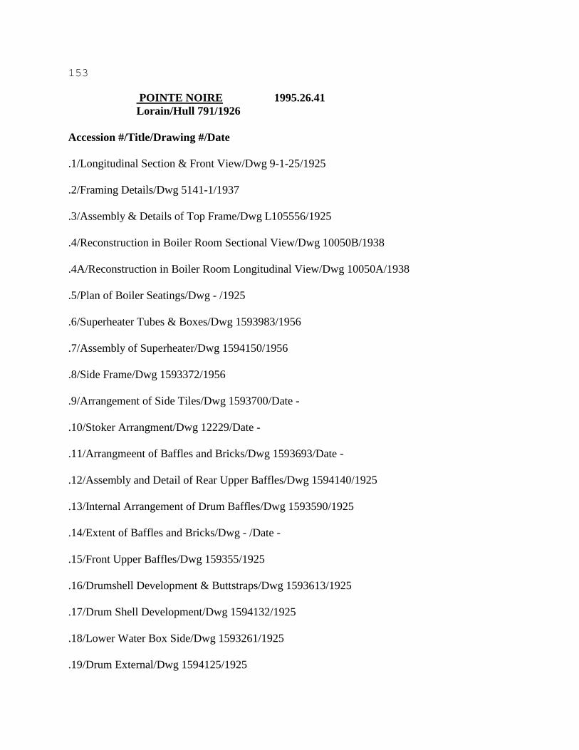
153
POINTE NOIRE 1995.26.41
Lorain/Hull 791/1926
Accession #/Title/Drawing #/Date
.1/Longitudinal Section & Front View/Dwg 9-1-25/1925
.2/Framing Details/Dwg 5141-1/1937
.3/Assembly & Details of Top Frame/Dwg L105556/1925
.4/Reconstruction in Boiler Room Sectional View/Dwg 10050B/1938
.4A/Reconstruction in Boiler Room Longitudinal View/Dwg 10050A/1938
.5/Plan of Boiler Seatings/Dwg - /1925
.6/Superheater Tubes & Boxes/Dwg 1593983/1956
.7/Assembly of Superheater/Dwg 1594150/1956
.8/Side Frame/Dwg 1593372/1956
.9/Arrangement of Side Tiles/Dwg 1593700/Date -
.10/Stoker Arrangment/Dwg 12229/Date -
.11/Arrangmeent of Baffles and Bricks/Dwg 1593693/Date -
.12/Assembly and Detail of Rear Upper Baffles/Dwg 1594140/1925
.13/Internal Arrangement of Drum Baffles/Dwg 1593590/1925
.14/Extent of Baffles and Bricks/Dwg - /Date -
.15/Front Upper Baffles/Dwg 159355/1925
.16/Drumshell Development & Buttstraps/Dwg 1593613/1925
.17/Drum Shell Development/Dwg 1594132/1925
.18/Lower Water Box Side/Dwg 1593261/1925
.19/Drum External/Dwg 1594125/1925
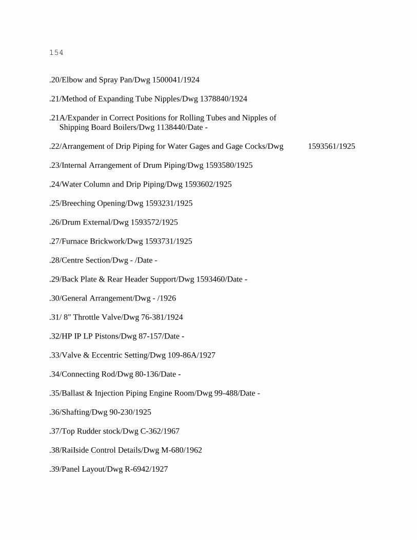
154
.20/Elbow and Spray Pan/Dwg 1500041/1924
.21/Method of Expanding Tube Nipples/Dwg 1378840/1924
.21A/Expander in Correct Positions for Rolling Tubes and Nipples of
Shipping Board Boilers/Dwg 1138440/Date -
.22/Arrangement of Drip Piping for Water Gages and Gage Cocks/Dwg 1593561/1925
.23/Internal Arrangement of Drum Piping/Dwg 1593580/1925
.24/Water Column and Drip Piping/Dwg 1593602/1925
.25/Breeching Opening/Dwg 1593231/1925
.26/Drum External/Dwg 1593572/1925
.27/Furnace Brickwork/Dwg 1593731/1925
.28/Centre Section/Dwg - /Date -
.29/Back Plate & Rear Header Support/Dwg 1593460/Date -
.30/General Arrangement/Dwg - /1926
.31/ 8" Throttle Valve/Dwg 76-381/1924
.32/HP IP LP Pistons/Dwg 87-157/Date -
.33/Valve & Eccentric Setting/Dwg 109-86A/1927
.34/Connecting Rod/Dwg 80-136/Date -
.35/Ballast & Injection Piping Engine Room/Dwg 99-488/Date -
.36/Shafting/Dwg 90-230/1925
.37/Top Rudder stock/Dwg C-362/1967
.38/RaiIside Control Details/Dwg M-680/1962
.39/Panel Layout/Dwg R-6942/1927

155
.40/Midship Section/Dwg 20-201/1905
.41/Proposed Modifications to Hold Bulkheads/Dwg - /1970
.42/Screen Bulkheads/Dwg 20/1922
.42A/Screen Bulkheads no. 75-123/Dwg 20/Date -
.42B/Half Section of New Screen bhd. at frs 59, 99 & 139/Dwg - /1970
.43/Screen & End Slope bhds, Arches, Scuttles & Walkways/Dwg 982-1063A/1955
.44/Bulkhead no. 25/Dwg 21/1922
.45/Longitudinal Section Tank Top and Butt Plan/Dwg 20-202/1955
.46/Plan View of Tank Top/Dwg - /Date -
.47/Tank Top Details/Dwg 982-1061/1955
.48/New Side Tank Details/Dwg 982-1062/1955
.49/WT bhd no. 172 & Coal Bunker Floor/Dwg 22/1922
.50/After Cabin Plan/Dwg 25A/1924
.51/Shell Expansion/Dwg 9/1922
.52/Proposed Oil Fuel Tank/Dwg - /1978
.52A/New Fuel Oil Tanks in Existing Coal Bunker Space/Dwg - /1971
.53/Fuel Oil Tank and Alterations to bhd 162, 163/Dwg GL21HS5501C/1950
.54/Changes in Cargo Hold Details for Admeasurement Photographs & Correspondence/Dwg -
/1956
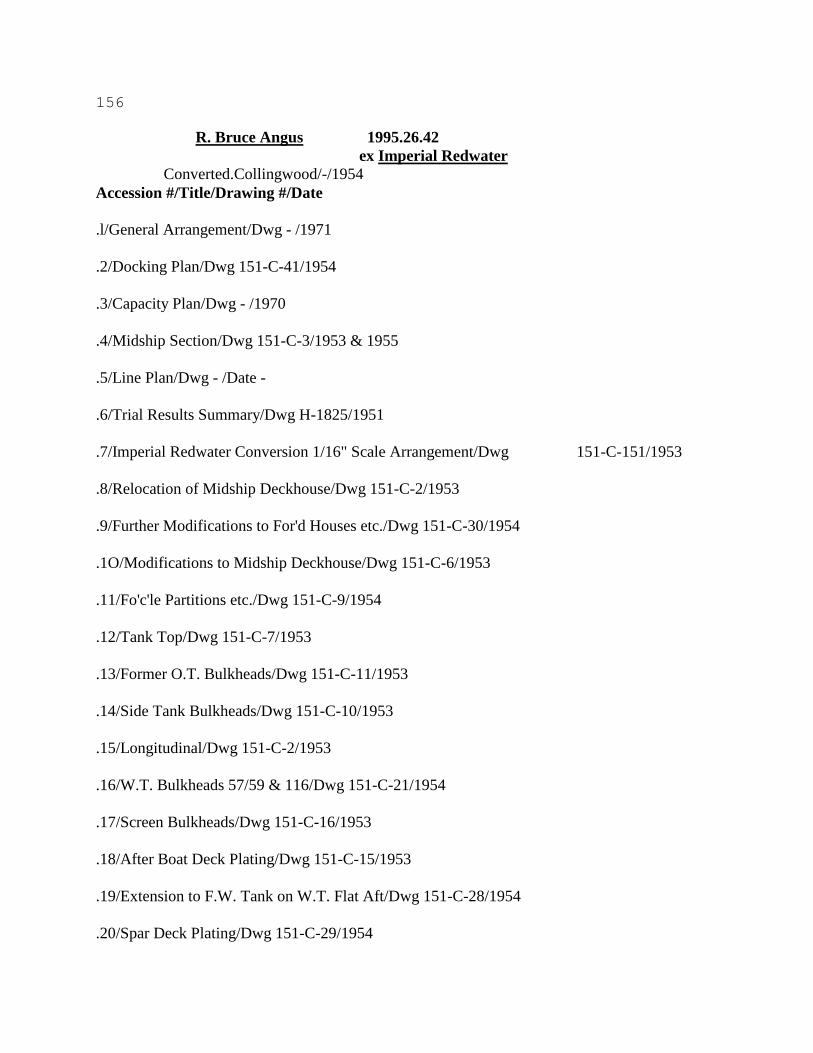
156
R. Bruce Angus 1995.26.42
ex Imperial Redwater
Converted.Collingwood/-/1954
Accession #/Title/Drawing #/Date
.l/General Arrangement/Dwg - /1971
.2/Docking Plan/Dwg 151-C-41/1954
.3/Capacity Plan/Dwg - /1970
.4/Midship Section/Dwg 151-C-3/1953 & 1955
.5/Line Plan/Dwg - /Date -
.6/Trial Results Summary/Dwg H-1825/1951
.7/Imperial Redwater Conversion 1/16" Scale Arrangement/Dwg 151-C-151/1953
.8/Relocation of Midship Deckhouse/Dwg 151-C-2/1953
.9/Further Modifications to For'd Houses etc./Dwg 151-C-30/1954
.1O/Modifications to Midship Deckhouse/Dwg 151-C-6/1953
.11/Fo'c'le Partitions etc./Dwg 151-C-9/1954
.12/Tank Top/Dwg 151-C-7/1953
.13/Former O.T. Bulkheads/Dwg 151-C-11/1953
.14/Side Tank Bulkheads/Dwg 151-C-10/1953
.15/Longitudinal/Dwg 151-C-2/1953
.16/W.T. Bulkheads 57/59 & 116/Dwg 151-C-21/1954
.17/Screen Bulkheads/Dwg 151-C-16/1953
.18/After Boat Deck Plating/Dwg 151-C-15/1953
.19/Extension to F.W. Tank on W.T. Flat Aft/Dwg 151-C-28/1954
.20/Spar Deck Plating/Dwg 151-C-29/1954
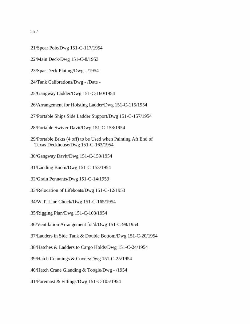
157
.21/Spear Pole/Dwg 151-C-117/1954
.22/Main Deck/Dwg 151-C-8/1953
.23/Spar Deck Plating/Dwg - /1954
.24/Tank Calibrations/Dwg - /Date -
.25/Gangway Ladder/Dwg 151-C-160/1954
.26/Arrangement for Hoisting Ladder/Dwg 151-C-115/1954
.27/Portable Ships Side Ladder Support/Dwg 151-C-157/1954
.28/Portable Swiver Davit/Dwg 151-C-158/1954
.29/Portable Brkts (4 off) to be Used when Painting Aft End of
Texas Deckhouse/Dwg 151-C-163/1954
.30/Gangway Davit/Dwg 151-C-159/1954
.31/Landing Boom/Dwg 151-C-153/1954
.32/Grain Pennants/Dwg 151-C-14/1953
.33/Relocation of Lifeboats/Dwg 151-C-12/1953
.34/W.T. Line Chock/Dwg 151-C-165/1954
.35/Rigging Plan/Dwg 151-C-103/1954
.36/Ventilation Arrangement for'd/Dwg 151-C-98/1954
.37/Ladders in Side Tank & Double Bottom/Dwg 151-C-20/1954
.38/Hatches & Ladders to Cargo Holds/Dwg 151-C-24/1954
.39/Hatch Coamings & Covers/Dwg 151-C-25/1954
.40/Hatch Crane Glanding & Toogle/Dwg - /1954
.41/Foremast & Fittings/Dwg 151-C-105/1954
158
.42/Additional Crew Rooms spar dk. fwd./Dwg 151-C-153/1953
.44/Landing Booms/Dwg - /1954
.45/Ventilating Fans for Engine Room/Dwg - /1953
.46/Pumping Arrangement/Dwg 151-C-102/1953
.47/Ballast Manifold/Dwg E-1359/1953
.48/Ballast Piping in Eng. Room/Dwg E-1358/1953
.49/ 20" Hydraulically Operated Main Ballast o'b'r'd Disch. Valve Assembly/Dwg E-1309/1953
.50/ 20" Main ballast Pump sea Chest/Dwg G-3103/1953
.52/ 18" x 20" Class "SLHV" Vertical Pump/Dwg 561203/1953
.53/Wastes and Drains/Dwg 89/1950
.54/Deck Steam and Exhaust/Dwg 151-C-99/1954
.55/Steam Smothering - Oil Fuel Bunkers/Dwg E-1394/1954
.56/Forward Heating Arrangement/Dwg 151-C-97/1954
.57/Oil Fuel Hose Outrigger Details/Dwg 151-C-154/1954
.58/Proposed Piping Arrangement for Steam Tyfons/Dwg K-1773/1951
.59/Hot and Cold Potable Water System/Dwg 151-C-100/1954
.60/Potable Water Tank & Seat Sewage Tank Seat For'd/Dwg 151-C- 13/1953
.61/Fire and Wash Deck Line/Dwg 151-C-114/1954
.62/Priming Piping/Dwg E-1371/1954
.63/Diagrammatic Potable Water Piping/Dwg K-1896/1954
.64/Vacuum Tank/Dwg G-3115/1954
.65/ 5" Potable Water Sea Chest/Dwg G-3104/1953
159
.66/Overboard Discharges/Dwg G-3106/1953
.67/Oil Fuel Piping/Dwg E-1365/1953
.68/Heating Coils - Oil Fuel Bunker/Dwg G-3108/1953
.69/Oil Fuel Bunkers/Dwg 151-C-18/1954
.70/Washplates in O.F. Bunkers/Dwg 151-C-23/1954
.71/Alteration Windlass Cover/Dwg - /1954
.72/Septic Tanks & Seats/Dwg - /1950
.73/Aft Bulwark/Dwg 151-C-26/1954
.74/Rudder/Dwg 97/1950
.75/Cast Steel Rudder Stock/Dwg - /1951
.76/Side Waterwall & Roof Tile/Dwg C503-95-A/1950
.77/Rear Water Circulating Section "Watts" 43 Series Boiler
W.P. 30 P.S.I./Dwg G-3102/1953
.78/Gauge Board Extension Showing Bailey Meter Accommodation/Dwg
G-3111/1953
.79/Boiler Room Gauge Board Showing Bailey Meter Accommodation/Dwg H-
2003/1954
.80/King Gauges Piping/Dwg E-1375/1954
.81/Safety Valves/Dwg 40869/1948
.82/Emergency Governor/Dwg - /1982
.83/Assembly of Insulated "Hex-press" F.D. Register with
"Hex-press" Atomizer/Dwg 40048-S-2-A/1944
.84/Soot Blower/Dwg 3-18618/1951
.85/F.D. Fan/Dwg 552363/1953
160
.86/Fan Damper and Frame/Dwg 552362/1953
.87/Water Gauge Mounting/Dwg C-525-248/1952
.89/Henschel Telephone sys./Dwg 2/1954
.90/Electro-vox Intercom/Dwg 1/1954
.91/Alarm Horns/Dwg 3/1954
.92/Elect. Power Schem./Dwg - /1954
.93/Cargo and Tunnel Lighting/Dwg - /1954
.94/Schematic Wiring Diagram 115V.S.PH. 60 Cycle Emergency
sw.board/Dwg 1/1952
.95/Schematic Wiring Diagram Panel Circuits 230V.A.C.3 PH.60 cy.sw.bd/Dwg - /1952
.96/115 Volt Lighting Schematic/Dwg - /1954
.97/W.T. Roller Chock/Dwg 152-C-164/1953

161
Red Wing 1995.26.43
ex Imperial Edmonton
Converted.Port Weller/-/-1960
Accession #/Title/Drawing #/Date
.1/Capacity plan/Dwg 28-8-75-82/1960
.2/General arrangement/Dwg - /1960
.2A/General arrangement & deck plan/Dwg YD571-S9-2-2/1960
.2B/General arrangement forward/Dwg - /1959
.3/Midship section/Dwg - /1959
.4/Shell expansion/Dwg - /1959
.5/Hydrostatic curves/Dwg 28-H-68/1960
.6/Loading guidance manual/Dwg - /1960
.6A/Diesel oil fuel tanks port tank shewn stbd similar/Dwg 28-H-74/1960
.7/Guidance plan/Dwg 58-26-A/1959
.8/Stern anchor & mooring arrangement/Dwg 28-H-37/1960
.9/Dock winch/Dwg 52604/1955
.10/Winch seats & P.C. fairleads/Dwg 28-H-63/1960
.11/Cargo hatch clamps/Dwg 28-H-7/1959
.12/Cargo hatches/Dwg 28-H-36/1960
.13/Hatch cover crane/Dwg 53944/1960
.14/Profile & deck/Dwg - /1959
.15/Aft section curves/Dwg - /Date -
.17/Upper deck platings/Dwg - /Date -
162
.18/Upper deck accommodation inside poop/Dwg 28-H-19/1959
.19/Poop deck house bhds/Dwg 390-740-2/1948
.20/Poop deck plating/Dwg - /Date -
.21/Proposed ammendments to PWDD Drwg no 28 Forward accommodation/Dwg - /1959
.22/Upper deck for'd modifications to accommodation//Dwg - /1960
.23/Preliminary forward houses/Dwg 28-H-60/1960
.24/Spear pole, jack staff & ensign staff/Dwg 28-H-84/1960
.25/Tank top plating double bottom floors & girders/Dwg 28-H-3/1959
.26/Hold bulkheads 85-111-137-165 & 193/Dwg 28-H-8/1959
.27/Longl. W.T. bhds., side tank bhds. & midship framing/Dwg 28-H-9/1959
.28/Upper & forecastle deck plating and W.T. flat for'd/Dwg 28-H-15/1959
.28A/Pilothouse arrangement/Dwg 28-H-73/1960
.29/Roughing in plan of kitchen equipment/Dwg 1519.B/1959
.30/Funnel/Dwg 28-H-83/1960
.34/Diagrammatic piping layout/Dwg L-92658-A/1941
.35/Priming system/Dwg 28-P-14/1960
.36/ 12" Ballast manifolds/Dwg 24-M-8/1956
.37/Ballast and pumping plan/Dwg 28-P-l/1959
.38/Details for ballast and pumping plan/Dwg 28-P-2/1959
.39/Main & aux. circulating and aux. ballast ov'bd. discharges/Dwg 28-H-52/1960
.40/Sketch of existing rudder palm/Dwg 28-H-10/1959
.41/Stern frame/Dwg 241-703-A/1941

163
.48/Arrangement of machinery plans/Dwg 241-901-11/1941
.49/Shell Plating Data/Dwg - /1947

164
THORNHILL 1995.26.44
Great Lakes Engineering Works/Hull 22/1906
Accession #/Title/Drawing #/Date
.1/Midship section/dwg - /1905
.1A/After joiner plan/dwg - /1950
.2/Hydrostatics/dwg - /1968
.3/Profile view - Alt. #2/dwg - /1952
.4/New channel in way of break in tank top/dwg - /1930
.5/Tank top reconstruction/dwg - /1959
.5A/New tank top/dwg - /1959
.5B/Alterations & additions tank top/dwg H-1/1936
.5C/Reconstruction of side tanks/dwg GL21H-S11-5-1/1945
.5D/Fuel oil tank & alteration to bhd 162, 163/dwg 21H-S55-0-1/1950
.6/Tank top sights/dwg YD564-S29-9-1/1959
.7/Brickwork arrangement - Superheater header side &
front/dwg E-162-655-0/1950
.8/Arrg't of side casing superheater header side/dwg E-162-653-1/1950
.9/Arrg't of side casing superheater removal side/dwg E-162-657-1/1950
.10/Arrg't of airheater & casing/dwg E-162-652-1/1950
.11/Foundation plan/dwg D-162-456-0/1950
.12/Arrg't of front casing/dwg E-162-659-1/1950
.13/Arrg't of rear casing/dwg E-162-659-1/1950
.14/Brickwork standard sections & details/dwg D-161-719-3/1948
165
.15/Brickwork arrangement superheater element removal side &
front/dwg E-162-656-1/1950
.16/Brickwork arrangement - floor/dwg D-162-472-0/1950
.17/Arrg't by-pass damper/dwg D-162-457-0/1950
.18/Arrangement of marine boilers SM type/dwg MND-10444-3/1950
.19/Arrg't & details of drum internals/dwg E-162-650-0/1950
.19A/Details of steam drum/dwg E-162-649-3/1950
.19B/Pressure parts assembly/dwg E-162-648-3/1950
.20/General arrangement/dwg E-612-646-1/1950
.21/Superheater arrangement/dwg E-162-651-2/1950
.22/Arrg't of valves & fittings/dwg E-162-647-1/1950
.23/List of equipment (sht. 1)/dwg 100-169/1951
.24/Diagrammatic arrangement of feed condensate piping/dwg 62-1274/1951
.25/Arrg't of auxiliary steam & exhaust piping/dwg 62-1303/1951
.25A/Arrg't of auxiliary steam & exhaust piping/dwg 62-1299/1951
.25B/Arrg't of auxiliary steam & exhaust piping/dwg 62-1301/1951
.26/Arrg't of machinery stbd elevation/dwg 100-165/1950
.27/Arrg't of machinery section/dwg 100-167/1950
.28/Arrg't of machinery port elevation/dwg 100-164/1951
.29/Location of connections at fuel oil tanks/dwg 62-1327/1950
.30/Location of sea chests and overboard discharges/dwg 98-643/1950
.31/Arrg't of vents, soundings & overflow fuel oil piping/dwg
99-641/1950
166
.32/Arrg't of bilge syphons in boiler room/dwg 62-1307/1950
.33/Arrg't of DO filling piping/dwg 62-1324/1951
.33A/Arrg't of fuel oil piping/dwg 62-1322/1950
.34/Diagrammatic arrg't of fuel oil system/dwg 62-1319/1950
.35/Diagrammatic assembly of main gear reduction &
turbines/dwg E-21876/1950
.35A/Main gear reduction & turbines/dwg G-15551/1950
.35B/Assembly marine gear reduction/dwg G-15552/1950
.35C/HP Assembly turbine/dwg G-15504/1950
.35D/LP Turbine assembly/dwg G-15505/1950
.36/Assembly marine gear reduction/dwg G-15556/1950
.37/General arrg't of shafting geared turbine drive/dwg 90-520/1950
.37A/Details of line shaftings/dwg 90-521/1950
.38/Line shaft bearing for 10.25" dia. shaft/dwg 83-188/1950
.39/Arrg't of steering gear aft 9" x 9" steering eng. type
da./dwg 105-527/1950
.40/Rudder & stern post assembly/1949
.41/Oertz rudder/dwg 29125/1929
.41A/Sternline rudder type "A"/dwg S-22-0-104/1952
.42/One line diagram electrical system/dwg 101-592/1950
.43/Power system list of motor-driven aux's/dwg 101-609/1950
.44/Inter-communication system wiring/dwg 101-612/1950
.45/Generator switchboard 1700/dwg - /1950
167
.46/Turbo generators & DC feeders front & sect. view ass'y floor
plan/dwg CN7209/1948
.47/Turbo generator & DC feeders rear top & sect. view
ass'y/dwg CN7210/1948
.48/Turbo generator & DC feeders rear view diagram/dwg - /1947
.49/Details of ordinary & web frames & intermediate stiffener/dwg - /Date -
.50/Rope guard & retainer plate/dwg 91-195/1950
.51/Shell expansion/dwg - /Date -
.52/Pilot house & texas/dwg - /Date -
.53/Deck plating/dwg - /Date -
.54/Steel plan of after deck house/dwg - /Date -
.55/New dunnage deck/dwg H-4/1936
.56/Alterations to blkhd #29 & stairway to main deck/dwg H-6/1936
.57/Bulkhead #190/dwg - /Date -
.58/Alterations to bulkhd #159/dwg -/1936
.59/Reconstruction of aft bhd #159/dwg GL21H-S11-5-2/1947
.60/Alteration to stern tube/dwg 91-228/1952
168
WHEAT KING 1995.26.45
ex M.V. LLANDAFF
Lithgow Ltd./Hull 61/1952
Accession #/Title/Drawing #/Date
.1/Proposed lengthening general arrangement/Dwg 61-H-101 0/1975
.2/Proposed lengthening general arrangement/Dwg 441-D-2/1974
.3/General arrangement/Dwg 276-H-26/1961
.3A/General arrangement/Dwg - /1960
.4/Capacity plan/Dwg 61-D-2/1975
.5/Midship section (lengthened section) & corrugated bhd/Dwg 61-H- 2/1975
.6/Midship section/Dwg 441-D-1/1975
.7/Midship section/Dwg 276-H-1/1960
.9/Design of ship's lines/Dwg - /Date -
.1O/Paint lines & schedule (sht. 1)/Dwg 61-H-106/1975
.11/Keel to paint line new section (sht. 2); Topsides - above paint line (existing ship) (sht. 3); Inside of
cargo holds D.B. &
ballast tanks (new section) (sht. 4)/Dwg 61-H-106/Date -
.12/Cross curves of stability/Dwg - /Date -
.15/Arrg't & detail of lifting & backhaul posts & sheaves/Dwg CV59/1957
.16/Lifeboat arrangement & davit seats/Dwg 276-H-21/1960
.17/Modifn to existing oil fuel bunkers/Dwg 276-H-9/1960
.18/PC Fairleads & winch seats/Dwg 276-H-23/1960
.19/Hold drain wells/Dwg 276-H-12/1960
.20/Stowage plan for no. 2 hatch/Dwg - /1957
.21/Stowage plan for no. 3 hatch/Dwg - /1960
169
.22/Stowage plan for no. 5 hatch/Dwg - /1960
.23/Proposed hatch arrangement/Dwg - /1960
.24/Hatch cover lifting post & pulley arrgt/Dwg 276-H-29/1961
.25/Proposed arrgt of cargo holds & double bottom floors/Dwg -/1960
.25A/Tank top & double bottom floors in hold no. 1/Dwg 276-H-6/1960
.26/Modifn to existing W.T. bulkheads/Dwg 276-H-7/1960
.27/Longitudinal bulkhead & sloped trimming plate/Dwg 276-H-10/1960
.28/Modification to longitudinal bulkd & fly to midship
section/Dwg 276-H-20/1960
.29/Modifn to existing upper deck/Dwg 276-H-6/1960
.30/Escape hatches to holds/Dwg 276-H-30/1961
.31/Section at fr 51 (poop front) showing reduced widths of
nav bridge & lower bridge/Dwg - /1960
.32/Proposed accommn arrgt upper loop & boat decks/Dwg - /1960
.33/Side views of the two vertical stiffeners/Dwg - /Date -
.33A/Stiffening of eng room bulkhead at fr 21/Dwg - /1972
.34/Machinery arrangement/Dwg - /1960
.34A/Ship arrangement Cont./Dwg 276-M-6/1962
.35/Pipe arrangement steam, exhaust, feed & air/Dwg 70260/1952
.35A/Pipe arrangement steam, exhaust, feed & air/Dwg 70263/1958
.35B/Pipe arrangement steam, exhaust, feed & air/Dwg 70261/1952
.36/Pipe arrangement steam, exhaust & feed/Dwg 70264/1952
.36A/Pipe arrangement steam, exhaust & feed/Dwg 70262/1952
170
.37/Steam, exhaust, feed & condensate diagram/Dwg 3285-200-3/1972
.38/Pipe arrangement steam, exhaust & air/Dwg 70265/1952
.39/Lubricating oil diagram/Dwg 3285-200-1/1972
.40/Fuel oil diagram/Dwg 3285-200-2/1972
.40A/Modifications to F.O. filling & transfer in eng.
room/Dwg 276-P-7/1960
.41/Bow thruster installation fuel oil lub oil & S.W. circulating
diagrammatics/Dwg 61-2030-1/1975
.44/Diagrammatic arrangement of bilge & ballast piping in
engine room/Dwg 3285-200-6/1972
.44A/Arrangement of O.F. piping & bilge & ballast pumping/Dwg -/1960
.45/Main ballast sea bay/Dwg 276-H-11/1960
.45A/Ballast & pumping plan/Dwg 276-P-3/1960
.45B/Diagrammatic arrangement of ballast system/Dwg 276-P-2/1960
.46/Pipe arrangement ballast, oil fuel, & cooling water suction &
discharge/Dwg 70254/1952
.47/Sea inlet boxes for SS generators S.W. circulating /Dwg 3285-200- 8/1972
.50/Air storage tanks/Dwg 36882/1951
.51/Auxiliary boiler/Dwg - /1951
.52/Fire extinguishing arrgt/Dwg 276-E-14/1960
.53/Modifn to existing oil fuel bunkers/Dwg 276-H-9/1960
.54/Shell expansion/Dwg - /1962
.55/Cargo oil pumping arrangement/Dwg - /1960
.56/Main cargo pump rooms (fore & aft)/Dwg - /1960

171
.57/Tunnel shafting/Dwg 30355/1953
.57A/Shafting arrangement/Dwg 96-108-02 A.B./1975
.57B/Shafting arrangement/Dwg 96-108-02 A./1975
.58/Propeller shaft & stern tube/Dwg 21795/1952
.58A/Propeller telemotor diagram/Dwg 585920/1975
.59/Propeller (spare)/Dwg 21877/1952
.60/Propeller/Dwg L.2384/1951
.61/Streamline rudder/Dwg - /1962
.62/Cast steel sternframe/Dwg - /1962
.63/Piston skirts/Dwg 12461/Date -
.64/Typical arrangement of lower scraper ring carrier with double
scraper rings/Dwg 18891/1963
.65/Arrangement of doxford bibby detuner/Dwg 12641/1951
.66/Details of detuner/Dwg 12640/1951
.67/Sketch showing clearance between crankweb and main engine
plates/Dwg 7551/Date -
.68/Stiffening plates in bedplate 67.L.B.D. 6./Dwg 7395/Date -
.69/Diagrammatic arrangement of fuel pipes for doxford engine
conversion to heavy fuel oil/Dwg 7915/1963
.70/Arrangement of heavy O.F. equipment & connections/Dwg 70254.A./1953
.71/Wiring diagram frame no. 1-2-4/Dwg MS4/Date -
.71A/Elementary for frames 1-2-4/Dwg MS2/Date -
172
.72/Elementary frame no. 3 & 5/Dwg MS3/Date -
.73/ 7 Frame main switchboard/Dwg MS1/Date -
.74/Frame no. 3/Dwg MS5/1971
.75/Terminal boxes no. 1 & no. 2/Dwg C-1687-1/1961
.76/Cable & equipment layout/Dwg D-2293-1/1961
.77/Single line diagram/Dwg E-1459-1/1961
.78/Wiring layout cargo holds & tunnels/Dwg E-1456-1/1961
.79/Emergency fire pump sea suction/Dwg 276-H-15/1960
.80/Arrangement of chainwheel on camshaft/Dwg 147244/1967
.81/Adjustment of chainwheel on camshaft/Dwg 147245/1967
.82/Crosshead bearing/Dwg 1392A73/1967
.83/Main bearing/Dwg 1414A36/1967
.84/Crankpin bearing/Dwg 1429A61/1967
.85/Bearing in thrust block/Dwg 1446A2/1967
.86/Detail Of Supply & Exhaust Ventilator Heads Serving Bow Thruster Engine Room/Dwg 61-H-121
(Sheet 2)/1976
.87/Engine Wiring D-398 Bow Thruster Engine/Dwg C-1220/1975
.88/General Arrangement Cat. D. 398 Marine Bow Thruster Drive/Dwg E- 0632/1975
.89/Bow Thruster Diesel Engine Control Schematic/Dwg 61-2005- 10/1975
.90/Arrangement Of Salt Water And Misc. Piping In Bow Thruster Compartment/Dwg 61-2030-1-
B/1976
.91/Bow Thruster Installation - Fuel Oil Lub Oil & S.W. Circulating Diagrammatics/Dwg 61-2030-1-
A/1976
173
.92/Layout Of Hydraulic System For Bow Thruster Unit/Dwg 61-2650- 1/1975
.93/Access Stair To Bow Thruster Engine Compartment/Dwg 61-3260- 1/1975
.94/"Doxford" Water Coolant System/ Diagram On Overhead /Date -
.95/Bunker Arrangement/Dwg - /Date -
.96/Fuel Tanks Arrangement/ Diagram On Overhead /Date -
.97/Transverse & Guide Shoe./Dwg 12448/Date -
.98/Tank Calibrations/Dwg 276-H-34/1961
.99/Arrangement Of Fuel Valve/Dwg - /1972
.100/Emergency Lighting System/Dwg D-2923-1/1968
.101/Bottom Blow-Down Valve & Fabricated Steel Nozzle/ Sketch 1 /Date -
.102/Scum Valve & Fabricated Steel Nozzle/ Sketch 2 /Date -
.103/Crankshaft Assembly & Details/Dwg FSN-2-1/1942
.104/"Thrust"/Sketch 3/Date -
.301/Boiler/Dwg B24027/1971
174
Inverewe 1995.26.47
ex. Atlantic Trader
Askers Mek Verstad/-/1961
Accession #/Title/Drawing #/Date
.1/As Fitted Diagram of Connections On Algonquin Unloading
Bridge/Dwg G-56-MI./Date -
.2/Capacity Plan/Dwg - /1961
.3/Capacity Plan/Dwg - /1961
.4/Trim And Stability/Dwg - /1961
.5/Profile And Plans As Built/Dwg S-141/1960
.6/General Arrangement/Dwg P-370/1960
.7/Midship Section As Built/Dwg S-140/1960
.8/Top Girder Assembly For ? /Dwg 51807/1961
.9/Full Ballast/Dwg - /Date -
.10/Trim And Stability Conditions &Angle OF Heel Caused By Loading Equipment/Dwg - /1966
.11/Schematic Diagram Of Connections For 500 Ton Algonquin Unloader. Folding Type/Dwg 61-93-
354/1963
.12/Proposed Alterations To Existing Crane Bridge/Dwg 1031-01/1966
.13/Arrangement Of Loading Boom/Dwg 1013-01/1966
.14/Arrangement Of Unloading Boom/Dwg 1013-02/1966
.15/Operating Instructions For Constant-Voltage Synchronous Generators/Dwg - /1961
Phosphore Conveyor 1995.26.47
Mitsubishi Heavy Industries/-/1969
.16/Additional Drainage Openings In Double Bottom W.B. Tanks/Dwg P.C.- 1/1977
.17/Additional Hatches In Upper Deck/Dwg P.C.-2/1977
.18/Proposed Wash Bulkheads In Saddle Tanks/Dwg P.C.-3/1977
175
.19/Fore Sealing Of Stern Tube/Dwg 226-701/1969
.20/Oil Lubrication Type Stern Tube/Dwg 226-431-B/1968
.21/Aft. Sealing Of Stern Tube/Dwg 226-702/1969
Self-Unloading Equipment 1995.26.47
.22/ 1000 Cu. Yd. Per Hr. Wheel Excavator/Dwg D-1000/1965
.23/Continuous Bulk Unloader - General Drawing/Dwg 47001-5/1963
.24/Self-Unloader - General Drawing Of Bow Section/Dwg 44107-32/1965
.25/Self-Unloader - General Sections Thru Wheel/Dwg 44107-33/1965
.26/Self-Unloader - General Drawing And Section Of Ship/Dwg 44107-34/1965
.27/Self-Unloader - Plan And Section Of Bow Area/Dwg 44107-37/1965
.28/Methods Of Self-Unloading For Bulk Cargo Ships/Dwg SKM1/1964
.29/Comparison Of Unloading Schemes/Dwg YS 837-S1-1/1965
.30/Arrangements Of Various Unloading Systems/Dwg YD-837-S27-1- 4/1965
.31/Comparison Of Unloading Schemes/Dwg - /1965
.32/Profiles - One Belt System/Dwg - /1965
.33/Proposed Layout Of Machinery For 50,000 Ton Self-Unloading Bulk Carrier For Leitch Transport
Ltd./Dwg - /1970
.34/Self-Unloading Equipment/ Sketch 1 /Date -
.35/Self-Unloading Equipment/ Sketch 2 /Date -
Reference Plans 1995.26.47
.36/S.S. Argyll - Unloading And Loading Equipment/Dwg - /1962

176
.37/S.S. Hochelaga - General Arrangement/Dwg BL-7600-1/1962
.38/M.S. Troll Forest - General Arrangement/Dwg 2-184-275/1970