introduction - san jose state university · way to getting more from your brookfield viscometer. it...
TRANSCRIPT
MORE SOLUTIONS TO STICKY PROBLEMS Page 1 Brookfield Engineering Labs., Inc.
When a piece of technical equipment is marketedsuccessfully for over 65 years, it is inevitable that alarge body of experience will develop from the use ofthat equipment. Procedures are established, papersare published, standards are accepted, and a vast in-formal grapevine of advice grows amidst the commu-nity of users. Such is the case with the Brookfield Vis-cometer. Accepted as a standard of viscosity mea-surement around the world, the Brookfield Viscometeris the nucleus of a library of information that encom-passes the experiences of thousands of users in aseemingly endless variety of applications.
This library, however, is not gathered convenientlytogether in any single location. It is fragmented, scat-tered here and there in technical journals, in test re-ports, in the notes made by technicians, researchers,and quality control people. For many users (particu-larly those new to the field of viscosity measurement),it is extremely difficult to gain access to informationgenerated outside their own company or industry.Brookfield Engineering Laboratories has for manyyears acted as a clearinghouse for this type informa-tion, reprinting a variety of technical papers on thesubject of viscosity measurement and making themavailable at no cost. This program has helped manypeople benefit from the experiences of others.
There is a middle ground, however, between the spe-cific technical information provided in these papers andthe basic operating procedures outlined in an instruc-tion manual for your instrument. We have been re-quested many times over the years to publish a bookthat would bridge the gap between the elementary andthe advanced, a sort of extended “user’s manual” thatwould guide the way for the person wishing to explorein greater depth the field of viscosity measurement,
with an emphasis on Brookfield equipment.The book you hold in your hand is the result of those
requests. It does not replace your instruction manual,nor does it replace the specific technical papers al-ready or yet to be published. It is also not a textbookon rheology. Rather, it is a guide to help point out theway to getting more from your Brookfield Viscometer.It does this in several ways:
S by offering practical advice on the use andmaintenance of the Brookfield Viscometerbased on our experience and that of ourcustomers;
S by suggesting ways in which specific pieces ofhardware may be used to solve viscositymeasurement problems;
S by explaining the basic principles of rheologyand their relation to measurements made withBrookfield equipment;
S by discussing factors that affect rheologicalbehavior and how these may be controlled;
S by outlining advanced mathematical proceduresfor detailed analysis of viscosity data;
S by consolidating a variety of useful range tables,formulas, and specifications for many BrookfieldViscometers and accessories.
We hope that you will find this book useful and referto it often. It is our attempt to answer all at once manyof the questions we have been asked over the years.If you have any questions that are not answered here,or if you want to suggest improvements or changes forfuture editions, please feel free to contact us. It was,after all, the input of people like yourself that madethis book possible in the first place.
INTRODUCTION
MORE SOLUTIONS TO STICKY PROBLEMS Page 2 Brookfield Engineering Labs., Inc.
1.1 Why Make Rheological Measurements?Anyone beginning the process of learning to think
Rheo-Logically must first ask the question, “Why shouldI make a viscosity measurement?” The answer lies inthe experiences of thousands of people who havemade such measurements, showing that much usefulbehavioral and predictive information for variousproducts can be obtained, as well as knowledge of theeffects of processing, formulation changes, agingphenomena, etc.
A frequent reason for the measurement of rheologicalproperties can be found in the area of quality control,where raw materials must be consistent from batch tobatch. For this purpose, flow behavior is an indirectmeasure of product consistency and quality.
Another reason for making flow behavior studies isthat a direct assessment of processability can beobtained. For example, a high viscosity liquid requiresmore power to pump than a low viscosity one. Knowingits rheological behavior, therefore, is useful whendesigning pumping and piping systems.
It has been suggested that rheology is the mostsensitive method for material characterization becauseflow behavior is responsive to properties such asmolecular weight and molecular weight distribution.This relationship is useful in polymer synthesis, forexample, because it allows relative differences to beseen without making molecular weight measurements.Rheological measurements are also useful in followingthe course of a chemical reaction. Such measurementscan be employed as a quality check during productionor to monitor and/or control a process. Rheologicalmeasurements allow the study of chemical,mechanical, and thermal treatments, the effects ofadditives, or the course of a curing reaction. They arealso a way to predict and control a host of productproperties, end use performance and materialbehavior.
1.2 Thinking Rheo-LogicallyTo begin, consider the question, “Can some
rheological parameter be employed to correlate withan aspect of the product or process?” To determinethis, an instinct must be developed for the kinds ofchemical and physical phenomena which affect therheological response. For the moment, assume thisinformation is known and several possibilities havebeen identified. The next step is to gather preliminaryrheological data to determine what type of flow behavioris characteristic of the system under consideration. Atthe most basic level, this involves makingmeasurements with whichever Brookfield Viscometeris available and drawing some conclusions based onthe descriptions of flow behavior types in Chapter 4.
Once the type of flow behavior has been identified,
more can be understood about the way componentsof the system interact (more information on what af-fects the rheological property can be found in Section4.7). The data thus obtained may then be fitted to oneof the mathematical models which have been success-fully used with Brookfield instruments. Many of thesemodels may be found in Chapter 5.
Such mathematical models range from the verysimple to the very complex. Some of them merely in-volve the plotting of data on graph paper; others re-quire calculating the ratio of two numbers. Some arequite sophisticated and require use of programmablecalculators or computers. This kind of analysis is thebest way for getting the most from our data and oftenresults in one of two “constants” which summarize thedata and can be related to product or process perfor-mance.
Once a correlation has been developed betweenrheological data and product behavior, the procedurecan then be reversed and rheological data may be usedto predict performance and behavior.
1.3 Three Schools of Thought on ViscosityMeasurement
In our experience there are basically three schoolsof thought on the use of viscometers in applicationsrheology. We present them here and invite you to de-cide which you fall into, remembering that there is no“right” one and that each has its merits.
1.3.1 The Pragmatic SchoolThe first school of thought is the most pragmatic.
The person who adheres to this school cares onlythat the Brookfield Viscometer generates numbersthat tell something useful about a product or pro-cess. This person has little or no concern aboutrheological theory and measurement parameters ex-pressed in absolute terms. Quality control and plantproduction applications are typical of this category.
1.3.2 The Theoretical SchoolThe second school of thought involves a more
theoretical approach. Those adhering to this schoolknow that some types of Brookfield Viscometers willnot directly yield defined shear rates and absoluteviscosities for non-Newtonian fluids. However, thesepeople often find that they can develop correlationsof “dial viscosity” with important product or processparameters. Many people follow this school ofthought. The applications rheology literature is re-plete with statements along the line of “I know thedata isn’t academically defined, but I keep this factin mind and treat the multi-point rheology informa-tion as if it were.” In many cases, this produces emi-nently satisfying results and eliminates the neces-sity of buying a highly sophisticated and very ex-pensive piece of rheological equipment.
CHAPTER 1
MORE SOLUTIONS TO STICKY PROBLEMS Page 3 Brookfield Engineering Labs., Inc.
1.3.3 The Academic SchoolThe third school of thought is quite academic in
nature. People adhering to this school require thatall measurement parameters, particularly shear rateand shear stress, be defined and known. They needequipment with defined geometries such as coneand plate or coaxial cylinders. Examples from theBrookfield line would be the Wells-Brookfield Cone/Plate and CAP Viscometers and the UL adapter,Small Sample Adapter, Thermosel, Din Adapter and
Spiral Adapter accessories, as well as the PVS Rhe-ometer. With this equipment the shear rate is de-fined and accurate absolute viscosities are obtaineddirectly.
That, then, is our view of the three schools ofthought on viscosity measurement. You may needto think in terms of any or all of these depending onyour background, approach, goals, and type of equip-ment available. Brookfield Viscometer users fall intoall three; the following chapters present informationof use to each.
2.1 Equipment for Specific SituationsThe purpose of this chapter is to provide an over-
view of Brookfield’s entire line of Viscometers and re-lated accessories, and to suggest ways in which theseproducts may be helpful in solving specific viscositymeasurement problems. This information will be use-ful to people adhering to all three schools of thoughton viscosity measurement.
The equipment has been organized into functionalgroups to help you quickly zero in on the items of mostinterest to you:
2.1.1 Viscometers2.1.2 Spindle Geometries2.1.3 Temperature Control2.1.4 Small Sample Volume2.1.5 Low Viscosity2.1.6 High Temperature2.1.7 Defined Shear Rate2.1.8 High Shear Rate2.1.9 Non-Flowing Sample Materials2.1.10 Fumes and Hazardous Locations2.1.11 Process Control
2.1.1 ViscometersBrookfield laboratory Viscometers are available
in three basic types: dial-reading (analog), digital,and programmable. The most significant differencebetween them is the manner in which the viscosityreading is displayed. The dial-reading type is readby noting the position of a pointer in relation to arotating dial; the Digital type is read by means of a3-digit LED display. In addition, the Digital Viscom-eter includes a 0-10mv output that may be connectedto a variety of devices, such as remote displays, con-trollers, and recorders.
In most respects dial-reading and Digital Viscom-eters are functionally similar. The operating proce-dures for both are essentially the same, they areavailable in the same model variations, they acceptthe same Brookfield accessories, and are generallyinterchangeable (model for model) in most viscos-
ity specifications requiring Brookfield Viscometers.The dial-reading type is the least expensive
Brookfield Viscometer and is suitable for most ap-plications where samples are to be tested over ashort period of time and a permanent detailed recordof rheological behavior is not required. This is dueto the fact that while the Viscometer rotates con-tinuously, readings may be made only intermittently,when the pointer passes under the vision glass, orwhen the reading is held and the Viscometerstopped. Long term viscosity tests necessitate fre-quent operator attention, and some fast-actingpro-cesses dictate continuous monitoring.
The Digital Viscometer, with its continuous sens-ing and recorder output, is more suited to such situ-ations. It may be left unattended for long periods,and the recorder speed may be adjusted to providea detailed record of even the fastest rheologicalprocesses. In addition, many operators prefer adigital display, which eliminates the interpolationsometimes necessary when reading a dial. TheDigital Viscometer, however, cannot be hand-heldduring use, unlike the dial-reading type. Both typesoffer equivalent accuracy.
All Brookfield laboratory Viscometers areavailable both in standard spindle and cone/plateconfigurations. See Section 2.1.8 for moreinformation on cone/plate spindle geometry.
It is not possible to convert a dial-readingViscometer to a Digital Viscometer, or to connect arecorder, printer or PC to it.
There are many variations of the standardViscometer models available, such as intermediatespring torques, alternative rotational speeds, andvarious physical modifications. Please consultBrookfield Engineering Laboratories or your dealerfor details and availability.
2.1.2 Spindle GeometriesAll Brookfield Viscometers are supplied with
spindles suitable for most applications within theviscosity range of the instrument. There are, how-ever, situations where specialized spindle geom-
CHAPTER 2
MORE SOLUTIONS TO STICKY PROBLEMS Page 4 Brookfield Engineering Labs., Inc.
etries are necessary to obtain optimum results.Brookfield has available a wide variety of spindlesand accessories to fulfill this need. Many are listedin this section.
All Brookfield Viscometer spindles are con-structed of 300 series stainless steel for mainte-nance-free service in most applications; some areavailable coated for maximum corrosion resistance.Please inquire about special spindle materials andconfigurations for unusual applications.
Disc SpindlesProvided as standard equipment with LV
(spindles #2 and #3) and RV/HA/HB models(spindles #1 through #6), these are general-purposespindles for use in containers of 600 mL capacity orlarger. Disc spindles produce accurate, reproducibleapparent viscosity determinations in most fluids. Theresults obtained can be converted into viscosityfunctions by a mathematical procedure outlined inTechnical Paper AR-82, available from BrookfieldEngineering Laboratories. See Section 2.1.7 forinformation on spindle geometries that directlyprovide defined shear rates.Cylindrical Spindles
These spindles (LV #1 and #4, RV/HA/HB #7)provide a defined spindle geometry for calculatingshear stress and shear rate values as well asviscosity. In all other respects their operatingparameters are similar to those of disc spindles.Because their defined geometry facilitatesmathematical analysis, cylindrical spindles arepar ticularly valuable when measuring non-Newtonian fluids. They are applicable to anyBrookfield Viscometer model with the use of theappropriate range sheet. Cylindrical equivalents ofthe LV #2 and #3 disc spindles are also available.See Section 2.1.7 for information on other definedshear rate geometries.Coaxial Cylinders
Coaxial-cylinder geometry is indicated forapplications where extremely well-defined shear rateand shear stress data is required, particularly whenthe sample volume is relatively small. SeveralBrookfield accessories feature coaxial-cylindergeometry; each also has unique advantages forspecific situations. These accessories are: the SmallSample Adapter (Section 2.1.4), the UL Adapter(Section 2.1.5), the Thermosel (Section 2.1.6), andthe DIN Adapter (Section 2.1.4).Cone/Plate Geometry
Cone/plate geometry offers absolute viscositydeterminations with precise shear rate and shearstress information readily available. The samplevolumes required are extremely small and thesample cup is jacketed for temperature control.Cone/plate geometry is particularly suitable for ad-vanced rheological analysis of non-Newtonian flu-ids. It is available on the Wells-Brookfield Cone/Plate
Viscometer (see Section 2.1.8 for more information).T-Bar Spindles
Generally used in conjunction with the HelipathStand accessory (with which they are supplied asstandard equipment), T-bar spindles make possiblethe measurement of non-flowing or slow-flowingmaterials such as pastes, gels, and creams. SeeSection 2.1.9.
2.1.3 Temperature ControlIn order to ensure maximum accuracy and
reproducibility in many viscosity measurementprocedures, temperature control is highlyrecommended. The following systems are availablefrom Brookfield:Temperature Baths
Constant-temperature baths are suitable formost viscosity measurement applications. They areavailable in two basic types: circulating, for use withjacketed devices such as the Wells-Brookfield Cone/Plate Viscometer (Section 2.1.8) and the SmallSample Adapter (Section 2.1.5); and reservoir/circulating, for all applications (this type can be usedwith jacketed devices as well as with any samplecontainer that can be immersed in the bath’sreservoir). Temperature baths are generally limitedto a maximum operating temperature ofapproximately 120°C (depending on the bath fluidused), and usually require auxiliary cooling devicesfor operation at or below ambient temperature.Refrigerated baths are also available. ContactBrookfield Engineering Laboratories or your dealerfor more information.Thermosel System
This system is designed for the measurementof small samples in the temperature range ofapproximately 40 to 300°C. Unlike a temperaturebath, the Thermosel doesn’t utilize a fluid mediumfor temperature control. For more information, seeSection 2.1.6.
2.1.4 Small Sample VolumeThe standard sample container for most
Brookfield Viscometers is a 600 mL low form Griffinbeaker. Users often find it desirable or necessaryto measure samples of smaller volume. SeveralBrookfield products feature small sample volumes.Small Sample Adapter
Specifically designed to facilitate themeasurement of small samples, the Small SampleAdapter is a jacketed, coaxial-cylinder accessorythat is compatible with all Brookfield Viscometerswith the exception of cone/plate types. Dependingon the model selected, the Small Sample Adapterutilizes sample volumes of 2.0 to 16.0 mL. Alsodepending on model, the Small Sample Adapter willmeasure viscosities from 5 cP to 10,000,000 cPat shear rates from 0.066 to 93.0 reciprocal seconds.The Small Sample Adapter’s jacketed design permits
MORE SOLUTIONS TO STICKY PROBLEMS Page 5 Brookfield Engineering Labs., Inc.
connection to a circulating-type bath for excellenttemperature control up to a recommended maximumof 100° C.UL Adapter
The UL Adapter is primarily intended to allowviscosity measurements in ranges below those nor-mally measurable by a particular Viscometer. Whenused with its removable end cap in place, the ULAdapter measures a sample volume of 16.0 mL. Formore information, see Section 2.1.5.DIN Adapter
The DIN Adapter, like the UL Adapter, isdesigned to measure in ranges below those normallymeasured with a particular Viscometer. The DINAdapter utilizes additional DIN spindles formeasurement ranges from 1 cP to 50,000 cP andconforms to DIN 53019.Thermosel System
The Thermosel System allows the measurementof viscosity at temperatures to 300°C. It incorporatescoaxial-cylinder spindle geometry that uses asample volume of 8.0 to 13.0 mL, depending on thespindle utilized. See Section 2.1.6.Wells-Brookfield Cone/Plate & CAP Viscometers
When sample volume is extremely limited, it maybe necessary to use the Wells-Brookfield Cone/PlateViscometer. It requires a sample of only 0.5 to 2.0mL, depending on spindle. More data on this in-strument will be found in Section 2.1.8.
The CAP Cone/Plate Viscometer requires <1mLfor sample volume. See Section 2.1.8 for details.
2.1.5 Low ViscosityEach Brookfield Viscometer measures a wide
range of viscosities; however, it occasionally be-comes necessary to measure viscosities below thenormal range of the instrument. Several pieces ofBrookfield equipment offer this capability:UL Adapter
This accessory was specifically designed toprovide greater sensitivity at low viscosities for theLV series Viscometers; it can, however, be used onany model Brookfield Viscometer except cone/platetypes. When mounted on an LVF or LVT Viscometer,the UL Adapter provides a viscosity range of 1.0 to10.0 cP and a defined shear rate of 73.4 reciprocalseconds at 60 RPM. For other Viscometer models,the minimum measurable viscosity with the ULAdapter in place is: RVT, 6.4 cP; HAT, 12.8 cP; HBT,51.2 cP. The UL Adapter features coaxial-cylindergeometry with a removable polyethylene end capfor the outer cylinder. With the end cap in place, theAdapter holds a sample volume of 16.0 mL and canbe immersed in a bath for temperature control up toa recommended maximum of 100°C; with the capremoved it may be used in sample containers ofalmost any size.Small Sample Adapter
With some spindle/chamber combinations, the
Small Sample Adapter permits measurement of vis-cosities below the Viscometer’s normal range.Check the applicable range sheet for details. Moreinformation on the Small Sample Adapter can befound in Section 2.1.4.Thermosel System
With certain spindles, the Thermosel Systemprovides increased sensitivity at low viscosities;check the applicable range sheet for more data. TheThermosel System is discussed in more detail inSection 2.1.6.Wells-Brookfield Cone/Plate Viscometer
The Wells-Brookfield Cone/Plate Viscometer haslow-viscosity capabilities as low as 0.1 cP. See Sec-tion 2.1.8 for more information on this instrument.
2.1.6 High TemperatureMeasurement of viscosity at high temperature
can be simple or complex, depending upon thesample materials and temperature. Sometimes allthat is necessary is to increase the distance betweenthe Viscometer and sample material through use ofspindle extensions (see Section 2.1.10). In difficultapplications, such as the measurement of moltenglass, it may be necessary to utilize a specializedfurnace and crucible, as well as custom-designedspindles constructed of heat resistance materials(consult with Brookfield Engineering Laboratoriesfor more information on this type application). Be-tween these two extremes, there is Brookfield equip-ment for most high temperature viscosity measure-ment applications.Thermosel System
The Thermosel System is specifically designedfor viscosity measurement of small samples in thetemperature range of approximately 25 to 300°C. Itis usually sold as a complete system includingViscometer, but it is also available as an accessoryto your present Viscometer (except cone/platetypes).
In addition to the Viscometer, the ThermoselSystem consists of a special coaxial-cylinder spindleand sample chamber, an electric heating apparatuscalled a thermocontainer, and a digital proportionaltemperature controller with RTD sensor. TheThermosel System is available in three variations:System 1 is a manual unit with a dial-reading Vis-cometer; System 2 includes a Digital Viscometer andoutputs for recording viscosity and temperature; andSystem 3, which adds the capabilities of a fully pro-grammable temperature controller to the featuresof System 2.
The Thermosel System requires small samplevolumes (8.0 to 13.0 mL, depending on spindle),and its coaxial-cylinder spindle geometry providesdefined shear rates in the range of 0.08 to 93.0 re-ciprocal seconds, depending on spindle and Viscom-eter model.Temperature Baths
MORE SOLUTIONS TO STICKY PROBLEMS Page 6 Brookfield Engineering Labs., Inc.
Brookfield Temperature Baths are also suitablefor viscosity measurements at high temperature.They generally are limited to a maximum operatingtemperature of 120°C. For more information, seeSection 2.1.2.
2.1.7 Defined Shear RateFor applications where viscosity data must be
expressed in absolute terms, it is necessary to usea spindle geometry for which shear rate and shearstress values can be calculated. Such defined op-erating parameters are found in the followingBrookfield instruments and accessories. Consult thereferenced sections for more information about theseproducts:
Cylindrical Spindles 2.1.2UL Adapter 2.1.5DIN Adapter 2.1.4Small Sample Adapter 2.1.4Thermosel System 2.1.6Wells-Brookfield Cone/Plate Viscometer 2.1.8CAP Viscometer 2.1.8
2.1.8 High Shear RateBrookfield Viscometers are, by design, relatively
low-shear instruments. The maximum shear rateachievable with most spindle configurations is usu-ally less than 100 reciprocal seconds. Defined shearrates in the range of up to 300 reciprocal secondscan be generated by some Viscometer models whenused in conjunction with the UL Adapter (Section2.1.5), the Small Sample Adapter (Section 2.1.4),or as part of the Thermosel System (Section 2.1.6).For shear rates in excess of 300 reciprocal secondsit is usually necessary to use the Wells-BrookfieldCone/Plate Viscometer, CAP Viscometer or PVSRheometer.Wells-Brookfield Cone/Plate Viscometer
The Wells-Brookfield Cone/Plate Viscometer willdetermine the absolute viscosity of small samplesunder conditions of defined shear rate and shearstress. Its cone and plate spindle geometry requiresa sample volume of only 0.5 to 2.0 mL and gener-ates shear rates in the range of 0.6 to l500 recipro-cal seconds (depending on Viscometer model andspindle used). The instrument’s sample cup is jack-eted for excellent temperature control.
Depending on the particular Viscometer modeland spindle in use, the Wells-Brookfield Cone/PlateViscometer will measure viscosities from 0.5 to 1.5million cP (although no single instrument will coverthis range, the use of several spindles will allowone Viscometer to measure a wide range of viscosi-ties).
The Wells-Brookfield Cone/Plate Viscometer isavailable in dial-reading and Digital versions. Atemperature bath is optional and highlyrecommended for precise and reproducible viscositymeasurements.
The cone and plate spindle geometry is avail-able only on the Wells-Brookfield Cone/Plate Vis-cometer; it is not available as an accessory or modi-fication of other Brookfield Viscometers. It is pos-sible to use this Viscometer with standard disc andcylindrical spindles, however; an extension for thelaboratory stand is required to provide sufficientclearance under the Viscometer.CAP Viscometer
The Brookfield CAP series of Cone/Plate Vis-cometers offer high shear rates and variable speedsin an instrument optimized for R&D and QC appli-cations such as paints, coatings, resins, inks, cos-metics, pharmaceuticals and foods. These seriesof viscometers offer high shear rate with integratedtemperature control for test sample volume of lessthan 1 mL.
The CAP series operates with automatic conegap positioning and viscosity range calibration andis offered as two models: CAP 1000 and CAP 2000.The CAP 1000 is a single speed viscometer andhas a fixed shear rate at 750 RPM on 50 Hz and9000 RPM on 60 Hz and generates shear rates at12,000 or 3,000 sec-1 at 60 Hz and 10,000 or 2,500sec-1 at 50 Hz. Viscosity ranges from .25 to 100Poise (0.25 to 10 Pa•s) depending on the conespindle used. The CAP 2000 is a variable-speedinstrument and has variable shear rate capabilityover the speed range from 50 to 2,000 RPM. Thisinstrument generates shear rates from 166 to 26,600 sec-1 at viscosity ranges from 0.1 to 1,500 Poise(0.1 to 150 Pa•s). Both the CAP 1000 and CAP2000 are accurate to ±2% of the full scale rangeand meet industry test standards BS3900, ISO 2884,and ASTM D-4287.PVS Rheometer
The Brookfield PVS Rheometer is a portable unitdesigned for measuring viscosity at high pressureand temperature. It’s ability to measure viscosityover a pressure range from abient up to 1,000 psiand a temperature range of -40°C to 200°C makesit ideal for applications such as oil and gas well drill-ing fluids, pulp and paper, plastics, petrochemicals,and aerosol based products.
The PVS Rheometer operates at shear ratesfrom 0.01 sec-1 to 1,700 sec-1 corresponding tospeed ranges from 0.05 to 1,000 RPM . The PVSRheometer torque sensor is unaffected by changesin pressure or temperature; the placement of baringsoutside the pressurized sample volume virtuallyelminates the need for maintenance.
2.1.9 Non-Flowing Sample MaterialsNon-flowing or slow-flowing sample materials
such as pastes, creams, and gels present specialproblems in viscosity measurement. Conventionalrotating spindles tend to “channel” (push the samplematerial aside), resulting in a continuouslydecreasing Viscometer reading that is of little value.The Helipath Stand is an accessory that eliminates
MORE SOLUTIONS TO STICKY PROBLEMS Page 7 Brookfield Engineering Labs., Inc.
this problem.Helipath Stand
The Helipath Stand is a motorized stand to whichany Brookfield Viscometer can be attached. TheStand slowly raises and lowers the Viscometer (at arate of 7/8-inch per minute) while a special T-barspindle rotates in the sample material. The crossbarof the spindle thus continuously cuts into freshmaterial, describing a helical path through thesample as it rotates. The “channeling” effect ofconventional spindles is completely eliminatedpermitting meaningful viscosity/consistencymeasurements to be made. A set of six T-barspindles and a special coupling are included withthe Helipath Stand.Spiral Adapter
The Brookfield Spiral Adapter accessory is apump-type sensor that directly measures viscosityof pastes, including applications such as solderpaste, foods, cosmetics and pharmaceuticals. TheSpiral Adapter has an inner, threaded spindlesurrounded by a concentric outer cylinder. Thiscombination causes the sample to be continuallypumped up through the Spiral Adapter. The materialreaches a steady state of flow during which viscosityis measured. The steady-state measurement is lesssensitive to sample handling and minor materialvariations than other viscosity measuring methods.
2.1.10 Special Accessory ItemsThe following items can be purchased for use
with Brookfield Viscometers/Rheometers.Quick Connect
The Brookfield Quick Connect accessory is de-signed to quickly attach or remove a spindle from aBrookfield Viscometer/Rheometer resulting in timesavings and elimination of cross threading. TheQuick Connect accessory is made of stainless steeland is used with LV, RV/HA/HA disk spindles as wellas T-bar couplings.Spindle Extensions
Spindle extensions are suitable for applicationsutilizing standard disc or cylindrical spindles wheredistance between the Viscometer and the samplemateria must be increased (up to 6 feet maximum).Type D extensions are installed between the Vis-cometer and the spindle, and are suitable for appli-cations where depth of the spindle immersion canbe observed. Type S extensions include the im-mersed portion of the spindle and are used wheredepth of immersion is not observable.Purge Fittings
A purge fitting may be provided on the pivot hous-ing of any Viscometer. An inert gas such as nitro-gen is introduced under low pressure through thepurge fitting, creating a positive pressure inside theViscometer housing which prevents entry of fumesand vapors.
Purge fittings are also available for sample cups
of the Wells-Brookfield Cone/Plate Viscometer andthe Thermosel System to provide a controlled at-mosphere for the sample being tested.Mercury Switch (Dial Viscometer Only)
In situations where potentially explosive orflammable fumes are present, precautions must betaken to eliminate any sources of sparking withinthe Viscometer. Since all Brookfield Viscometersutilize a brushless motor, the only potential sourceof sparking within the Viscometer is the power switch.Replacement of the standard switch with a non-sparking mercury switch is an inexpensive way ofmaking the Viscometer “explosion-safe” and isadequate for applications where danger ofexplosion is relatively slight, but additional safety isdesired. Be aware, however, of other possiblesources of sparking outside the Viscometer, suchas the line cord plug, and take appropriateprecautions. The mercury switch is available for dial-reading Viscometers only.Explosion-Proof Construction(Dial Viscometer Only)
When the danger of explosion is great due tothe presence of flammable fumes or other factors,use of approved explosion-proof equipment may berequired. Brookfield dial-reading Viscometers(except cone/plate types) are available inUnderwriters’ Laboratory (UL) approved explosion-proof versions. These instruments are approved forClass l, Group D hazardous locations. The DigitalViscometers and Rheometers are not available withexplosion-proof construction.
Electrically operated Brookfield accessories,such as the Helipath Stand and the Thermosel, arenot available in explosion-proof versions. They canbe used with explosion-proof Viscometers (some-times requiring special adapters), but only in non-hazardous environments.
2.1.11 Fumes and Hazardous LocationsWhenever fumes and vapors are present that
could enter the Viscometer, care should be taken toprevent such entry. When the fumes are explosiveor flammable, special precautions are required notonly for protection of the Viscometer, but for thesafety of nearby personnel. The preceding sectionsgive an overview of accessories and modificationsavailable for such applications.
2.1.12 Process ControlPractical application of viscosity data obtained
in the laboratory often involves use of on-line pro-cess viscometers and viscosity controllers.Brookfield manufactures a complete line of instru-mentation that has been applied to a wide variety ofprocess control applications. Please contactBrookfield Engineering Laboratories for more infor-mation.
MORE SOLUTIONS TO STICKY PROBLEMS Page 8 Brookfield Engineering Labs., Inc.
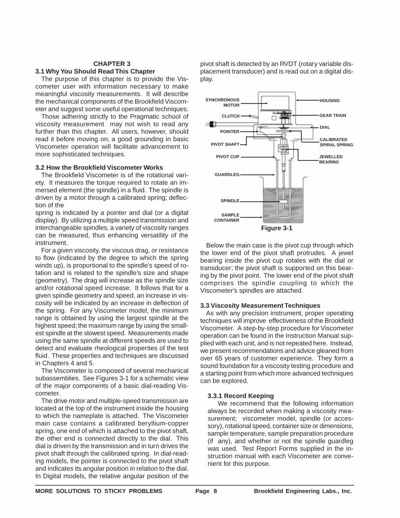
pivot shaft is detected by an RVDT (rotary variable dis-placement transducer) and is read out on a digital dis-play.
SYNCHRONOUSMOTOR
CLUTCH
POINTER
PIVOT SHAFT
HOUSING
GEAR TRAIN
DIAL
CALIBRATEDSPIRAL SPRING
JEWELLEDBEARING
PIVOT CUP
SPINDLE
SAMPLECONTAINER
GUARDLEG
Figure 3-1
Below the main case is the pivot cup through whichthe lower end of the pivot shaft protrudes. A jewelbearing inside the pivot cup rotates with the dial ortransducer; the pivot shaft is supported on this bear-ing by the pivot point. The lower end of the pivot shaftcomprises the spindle coupling to which theViscometer’s spindles are attached.
3.3 Viscosity Measurement TechniquesAs with any precision instrument, proper operating
techniques will improve effectiveness of the BrookfieldViscometer. A step-by-step procedure for Viscometeroperation can be found in the Instruction Manual sup-plied with each unit, and is not repeated here. Instead,we present recommendations and advice gleaned fromover 65 years of customer experience. They form asound foundation for a viscosity testing procedure anda starting point from which more advanced techniquescan be explored.
3.3.1 Record KeepingWe recommend that the following information
always be recorded when making a viscosity mea-surement; viscometer model, spindle (or acces-sory), rotational speed, container size or dimensions,sample temperature, sample preparation procedure(if any), and whether or not the spindle guardlegwas used. Test Report Forms supplied in the in-struction manual with each Viscometer are conve-nient for this purpose.
CHAPTER 33.1 Why You Should Read This Chapter
The purpose of this chapter is to provide the Vis-cometer user with information necessary to makemeaningful viscosity measurements. It will describethe mechanical components of the Brookfield Viscom-eter and suggest some useful operational techniques.
Those adhering strictly to the Pragmatic school ofviscosity measurement may not wish to read anyfurther than this chapter. All users, however, shouldread it before moving on; a good grounding in basicViscometer operation will facilitate advancement tomore sophisticated techniques.
3.2 How the Brookfield Viscometer WorksThe Brookfield Viscometer is of the rotational vari-
ety. It measures the torque required to rotate an im-mersed element (the spindle) in a fluid. The spindle isdriven by a motor through a calibrated spring; deflec-tion of thespring is indicated by a pointer and dial (or a digitaldisplay). By utilizing a multiple speed transmission andinterchangeable spindles, a variety of viscosity rangescan be measured, thus enhancing versatility of theinstrument.
For a given viscosity, the viscous drag, or resistanceto flow (indicated by the degree to which the springwinds up), is proportional to the spindle’s speed of ro-tation and is related to the spindle’s size and shape(geometry). The drag will increase as the spindle sizeand/or rotational speed increase. It follows that for agiven spindle geometry and speed, an increase in vis-cosity will be indicated by an increase in deflection ofthe spring. For any Viscometer model, the minimumrange is obtained by using the largest spindle at thehighest speed; the maximum range by using the small-est spindle at the slowest speed. Measurements madeusing the same spindle at different speeds are used todetect and evaluate rheological properties of the testfluid. These properties and techniques are discussedin Chapters 4 and 5.
The Viscometer is composed of several mechanicalsubassemblies. See Figures 3-1 for a schematic viewof the major components of a basic dial-reading Vis-cometer.
The drive motor and multiple-speed transmission arelocated at the top of the instrument inside the housingto which the nameplate is attached. The Viscometermain case contains a calibrated beryllium-copperspring, one end of which is attached to the pivot shaft,the other end is connected directly to the dial. Thisdial is driven by the transmission and in turn drives thepivot shaft through the calibrated spring. In dial-read-ing models, the pointer is connected to the pivot shaftand indicates its angular position in relation to the dial.In Digital models, the relative angular position of the
MORE SOLUTIONS TO STICKY PROBLEMS Page 9 Brookfield Engineering Labs., Inc.
3.3.2 The Spindle and the GuardlegExamine each spindle before using it. If it is cor-
roded or damaged to the extent of changing its di-mensions, a false viscosity reading may result. Sinceall spindles are brightly polished when new, any signof pitting, dulled edges, or other obvious damageshould dictate the purchase of a new spindle. If youhave an unusual problem along these lines, corro-sion-resistant 316 series stainless steel and Teflon-coated spindles are available. Also, special spindlematerials can be employed.
When attaching a spindle, remember that it hasa left-hand thread and must be screwed firmLy tothe coupling. Always lift up on the spindle couplingwhen attaching a spindle to avoid damage to theinstrument’s pivot point and jewel bearing. After at-tachment, do not hit the spindle against the side ofthe sample container since this can damage theshaft alignment. A good procedure to follow is toimmerse and position the spindle in the sample fluidbefore attaching it to the Viscometer.
The spindle guardleg (supplied with some mod-els) protects the spindle from damage and is sig-nificant to the Viscometer’s calibration when usingthe #1 or #2 spindle. The guardleg should be usedat all times. If it proves necessary or desirable tooperate the Viscometer without the guardleg, thisfact should be noted when reporting test results. Itmust be desirable to recalibrate the Viscometer tocompensate for the absence of the guardleg. Referto Section 3.3.10 for this procedure.
Note: spindle guardlegs are provided only onLV and RV models of the dial-reading and DigitalViscometers with standard spindles. HA and HBmodels, as well as Cone/Plate models, do not re-quire a guardleg. The guardleg is also not used inconjunction with most accessories.
3.3.3 Selecting a Spindle SpeedWhen performing a test according to an existing
specification or procedure, use the spindle andspeed specified (after confirming that you have thecorrect Viscometer model). When conducting anoriginal test, the best method for spindle and speedselection is trial and error. The goal is to obtain aViscometer dial or display reading between 10 and100, remembering that accuracy improves as thereading approaches 100 (see Section 3.3.7). If thereading is over 100, select a slower speed and/or asmaller spindle. Conversely, if the reading is under10, select a higher speed and/or a larger spindle.
If the approximate viscosity of the sample fluidis known, a faster method for honing in on the rightspindle/speed combination is available by referringto the Factor Finder supplied with the Viscometer.The goal is to select a combination whose rangebrackets the estimated viscosity of the sample.
For any given spindle/speed combination, the
maximum range available is equal to the spindleFactor multiplied by 100. This maximum is alsocalled “Full Scale Range” or “FSR”. For Digital Vis-cometers that have the AUTORANGE key, select-ing a speed and spindle and then depressing andholding the AUTORANGE key will cause the screento display FSR in cP.
The minimum recommended range equals theFactor multiplied by 10. For example: a #2 spindleon an LVT Viscometer at 12 RPM has a Factor of25. The maximum range of this combination is 25times 100, or 2500 cP. The minimum recommendedviscosity that should be measured is 25 times 10,or 250 cP. Therefore, if the viscosity of the samplefluid is estimated to be 4000 cP, another spindle/speed combination must be selected in order tomake the measurement. If the sample fluid is around2000 cP, however, this spindle and speed would besuitable. With a little practice, a quick glance at theFactor Finder will suffice to make an appropriateselection of spindle and speed.
When conducting multiple tests, the samespindle/speed combination should be used for alltests. When a test must be performed at severalspeeds, select a spindle that produces on-scalereadings at all required speeds. This may necessi-tate using a dial or display reading less than 10,which is acceptable as long as the reduced accu-racy of such a reading is recognized.
3.3.4 Sample Container SizeFor measurements with standard Viscometer
models we recommend a container with an insidediameter of 3 1/4 inches (83 mm) or larger. Theusual vessel for this purpose is a 600 mL low formGriffin beaker. Use of a smaller container will resultin an increase in viscosity readings, particularly withthe #1 and #2 spindle.
When utilizing a smaller container, the simplestapproach is to report the dimensions of the con-tainer and ignore the probable effect on calibration.As long as the same size container is used for allsubsequent tests, there will be no correlation prob-lem.
Alternatively, the Viscometer can recalibrated tocompensate for the smaller container as outlined inSection 3.3.10. Also, use of the Small SampleAdapter should be considered. See Section 2.1.4.
3.3.5 Sample ConditionsThe sample fluid should be free from entrapped
air. Air can be removed by gently tapping thecontainer on a table top or by using a vacuumapparatus.
The sample should be at a constant and uni-form temperature. This can be verified by checkingthe temperature at several different locations withinthe container. Be sure to bring the sample, spindle,and guardleg to the same temperature before tak-
MORE SOLUTIONS TO STICKY PROBLEMS Page 10 Brookfield Engineering Labs., Inc.
ing a viscosity reading. Temperature uniformity canoften be maintained by agitation prior to a measure-ment, but first determine that such agitation won’taffect viscosity of the sample fluid (see Section4.7.5). Factors used to calculate viscosity valuesfrom the Viscometer readings are independent oftemperature.
A constant temperature water bath is used tomaintain the desired temperature. Refer to Section2.1.3 for information on recommended baths.
High temperature work (up to 300°C) may re-quire use of the Thermosel accessory. See Section2.1.6.
Homogeneity of the sample is also quite impor-tant, especially in dispersed systems where settlingcan occur. In many cases, simple stirring just priorto the test will keep the components dispersed.
3.3.6 Spindle ImmersionThe spindle should be immersed up to the middle
of the shaft indentation. Failure to do so could re-sult in incorrect viscosity readings.
In some cases the sample fluid may change itsrheological structure during the act of spindle im-mersion. To avoid this, we recommend inserting thespindle in a different portion of the sample than theone intended for measurement. The spindle maythen be moved horizontally to the center of thesample container. This must be done before attach-ing the spindle to the Viscometer.
3.3.7 Sensitivity and AccuracyBrookfield Viscometers are guaranteed to be
accurate to within ± 1% of the full-scale range of thespindle/speed combination in use (this percentage,expressed in centipoise values, is equal to thespindle Factor; accuracy of a spindle/speed combi-nation with a factor of 25 would therefore be within± 25 cP). Repeatability is to within ± 0.2%.
The accuracy of a particular viscosity reading isdependent upon the actual dial or display reading.In general, accuracy of the viscosity value will in-crease as the readingapproaches 100. This is be-cause the tolerance of ± 1% of full-scale viscosityapplies to all readings, and represents a smallerpercentage of measured viscosity as the actualreading increases. Consider the following example:
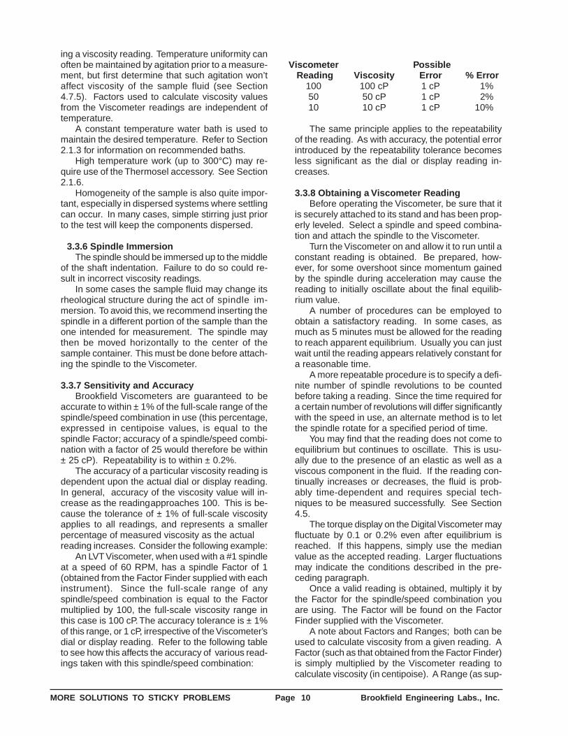
An LVT Viscometer, when used with a #1 spindleat a speed of 60 RPM, has a spindle Factor of 1(obtained from the Factor Finder supplied with eachinstrument). Since the full-scale range of anyspindle/speed combination is equal to the Factormultiplied by 100, the full-scale viscosity range inthis case is 100 cP. The accuracy tolerance is ± 1%of this range, or 1 cP, irrespective of the Viscometer’sdial or display reading. Refer to the following tableto see how this affects the accuracy of various read-ings taken with this spindle/speed combination:
Viscometer Possible Reading Viscosity Error % Error
100 100 cP 1 cP 1%50 50 cP 1 cP 2%10 10 cP 1 cP 10%
The same principle applies to the repeatabilityof the reading. As with accuracy, the potential errorintroduced by the repeatability tolerance becomesless significant as the dial or display reading in-creases.
3.3.8 Obtaining a Viscometer ReadingBefore operating the Viscometer, be sure that it
is securely attached to its stand and has been prop-erly leveled. Select a spindle and speed combina-tion and attach the spindle to the Viscometer.
Turn the Viscometer on and allow it to run until aconstant reading is obtained. Be prepared, how-ever, for some overshoot since momentum gainedby the spindle during acceleration may cause thereading to initially oscillate about the final equilib-rium value.
A number of procedures can be employed toobtain a satisfactory reading. In some cases, asmuch as 5 minutes must be allowed for the readingto reach apparent equilibrium. Usually you can justwait until the reading appears relatively constant fora reasonable time.
A more repeatable procedure is to specify a defi-nite number of spindle revolutions to be countedbefore taking a reading. Since the time required fora certain number of revolutions will differ significantlywith the speed in use, an alternate method is to letthe spindle rotate for a specified period of time.
You may find that the reading does not come toequilibrium but continues to oscillate. This is usu-ally due to the presence of an elastic as well as aviscous component in the fluid. If the reading con-tinually increases or decreases, the fluid is prob-ably time-dependent and requires special tech-niques to be measured successfully. See Section4.5.
The torque display on the Digital Viscometer mayfluctuate by 0.1 or 0.2% even after equilibrium isreached. If this happens, simply use the medianvalue as the accepted reading. Larger fluctuationsmay indicate the conditions described in the pre-ceding paragraph.
Once a valid reading is obtained, multiply it bythe Factor for the spindle/speed combination youare using. The Factor will be found on the FactorFinder supplied with the Viscometer.
A note about Factors and Ranges; both can beused to calculate viscosity from a given reading. AFactor (such as that obtained from the Factor Finder)is simply multiplied by the Viscometer reading tocalculate viscosity (in centipoise). A Range (as sup-
MORE SOLUTIONS TO STICKY PROBLEMS Page 11 Brookfield Engineering Labs., Inc.
plied with some Brookfield Accessories in lieu of aFactor) is equal to the Factor multiplied by 100.Therefore, to calculate viscosity, first divide theRange by 100, then multiply by the Viscometer dialor display reading.
3.3.9 A Calibration CheckPeople are often concerned about the accuracy
of their Viscometer. Here are some tests of its me-chanical performance:
(A) Variations in power frequency will causethe spindle to rotate at an incorrect speed. If youare in an area where electric clocks are used, thisfactor may be immediately eliminated. Voltage varia-tions have no effect as long as the deviation is notgreater than ± 10% of the nameplate voltage andthe frequency remains constant.Other readily apparent symptoms of improper powersupply are: failure of the motor to start, jerky spindlerotation, a wildly fluctuating pointer, or inconsistentdigital display readings.
(B) Damage to the pivot point or jewel bearingwill adversely affect accuracy and repeatability ofthe Viscometer. The following Oscillation Test willallow you to evaluate the condition of these compo-nents:
1. The Viscometer should be mounted and lev-eled, with no spindle installed and the powerswitch in the “off” position for Dial ReadingViscometers; Digital Viscometers should havethe power on, the motor off.
2. Turn the spindle coupling to deflect the pointeror digital display upscale from its zero posi-tion to a torque reading of 5 to 10 and let itswing back under its own power.
3. If the pointer swings freely and smoothly, andreturns to zero each time this test is repeated,the pivot point and jewel bearing are in goodcondition. If it crawls back or sticks on thedial, performance of the Viscometer will notbe up to specification, and it should beserviced. On Digital Viscometers the digitaldisplay should fluctuate smoothly and returnto a zero reading.
(C) We have never found a spring made ofberyllium copper which showed any change in itscharacteristics due to fatigue, even after hundredsof thousands of flexings. For this reason, a check ofthe calibrated spring is usually not necessary. Thereis no external zero adjustment on dial-readingmodels for the same reason. The zero adjustmenton Digital models is provided to compensate for anypossible heat-induced drift in the electronic circuitry.
(D) Use of a calibrated viscosity standard is rec-ommended as a final performance check. Test theviscosity standard as you would any sample fluid,carefully following any applicable instructions.Brookfield Viscosity Standards (calibrated to within±1%) are ideal for this test. The use of fluids other
than viscosity standards is not recommended dueto the probability of unpredictable rheological be-havior.
(E) If the Viscometer passes all of the preced-ing tests, its performance should be satisfactory.Should accuracy or operation of the instrument stillbe suspect, please refer to the troubleshooting chartin Section 3.5.
3.3.10 Recalibrating the Brookfield ViscometerIn many cases it is not practical to use a 600 mL
low form Griffin beaker when making measure-ments with a Brookfield Viscometer. It may be de-sirable to use a different container if transferring thematerial proves messy or time-consuming. Some-times people also use the instrument without theguard leg to avoid the extra cleaning that would oth-erwise be involved. Either of these practices requiresthat a recalibration of the instrument be made if ac-curate results are to be obtained.
If measurements have been made under oneset of conditions and you merely wish to establish areference point with the same material under newconditions, the following procedure will suffice:
1. Measure the material in both the old and newcontainer and/or with the guard leg removedand in place. Be sure that the same spindleand speed are used and that the tempera-ture of the material remains the same.
2. Note the new reading - this is the new refer-ence point corresponding to the originalvalue.
This procedure may be used in establishing con-trol methods to be followed when the Viscometer isto be used for quality control purposes, and the op-erator is not concerned with the actual centipoisevalue of the material.
If your work requires that actual centipoise val-ues be obtained, we suggest the following proce-dure if a different container is to be used or if youdon’t wish to use the guard leg:
(1) Following the procedures outlined earlier inthis chapter, measure the viscosity of aNewtonian fluid, using a standard containeras specified in Section 3.3.4. BrookfieldViscosity Standards are highlyrecommended for this procedure. Performthis measurement carefully, as the accuracyof your end result depends upon it. Multiplythe Viscometer reading by the appropriateFactor to determine the fluid’s viscosity incentipoise.
(2) Transfer the Standard to the container forwhich the Viscometer is to be calibrated.Ensure that the fluid temperature is the sameas it was during Step (1).
(3) Using the same spindle you intend to usefor subsequent sample testing, measure vis-
MORE SOLUTIONS TO STICKY PROBLEMS Page 12 Brookfield Engineering Labs., Inc.
cosity of the Standard in the new container.Note the dial or display reading and speed,S1.
(4) The new range of measurement is deter-mined by this formula:
R1 = ———100ηx
Where R1 is the full-scale range of measure-ment under the new conditions; η is the vis-cosity of the Standard as measured in step(1); and x is the dial or display reading ob-tained in step (3).
(5) To calculate the resulting new ranges whenthe same spindle is operated at differentspeeds under the new conditions, use thisformula:
R1 S2R2 S1
=
Where R1 is the range already establishedin Step (4) for RPM of S1, and S2 is thespeed for which range R2 is to be deter-mined.
(6) The multiplying factor (f) for the new condi-tions can be determined by this formula:
f = R1100
Where R1 is the range for the particularspindle and speed combination used, as de-termined in Step (4).To calculate viscosity, therefore, multiply thereading obtained on the Viscometer’s 0-100scale by f.
3.4 Viscometer MaintenanceBrookfield Viscometers are highly reliable, provided
the instrument is handled properly. Most problems arereadily detected by the Calibration Check in Section3.3.9. To prevent potential problems, a few pointersare worth remembering:
(A) The forces to which the Viscometer respondsare extremely small; the optimum performance ofthe instrument depends on the elimination of all un-necessary friction which may affect its sensitivity.This means cleanliness. Care must be taken to pre-vent dust, fumes, liquids, and other forms of con-tamination from entering the Viscometer housing.If it is necessary to use the instrument in such envi-ronments, use of the spindle extensions and/orpurge fittings is recommended to minimize the en-try of contaminants. More information on these ac-cessories can be found in Section 2.1.10.(B) Never place the instrument upside down with afluid-coated spindle attached.(C) Do not expose the Viscometer to ambient tem-peratures in excess of 75°C. When measuringsamples at high temperatures, the use of spindleextensions or the Thermosel accessory is recom-mended.
(D) Avoid applying side- or down-thrust to the spindlecoupling; this protects the pivot point and jewel bear-ing, which can be broken or dulled by rough treat-ment. Always lift the spindle coupling when attach-ing or removing a spindle. Do not strike the spindleagainst the sample container or otherwise applyside-thrust to it. Do not pull down on the spindle orspindle coupling.(E) Do not drop or severely jar the instrument. TheBrookfield Laboratory Stand provides a convenient,sturdy support. If the Viscometer is intended forportable use, it should be stored in its carrying casewhen not in use.
If the Viscometer is physically damaged or fails theOscillation Test in Section 3.3.9, it should be returnedfor repair to Brookfield Engineering Laboratories or tothe dealer from whom it was purchased.
The need for periodic preventative maintenance var-ies with the conditions of use. Under normal circum-stances, a yearly service should be sufficient to keepthe Viscometer in top working order. More severe usewill necessitate more frequent service. The instru-ment should be returned to Brookfield or one of itsdealers for this service.
3.5 Viscometer TroubleshootingSpecific fault diagnosis procedures are detailed in
the instruction manual that is provided with each Vis-cometer. The chart below lists some of the more com-mon problems that you may encounter while using yourViscometer, along with the probable causes and sug-gested cures.
Spindle Does Not Rotate❏ Make sure the viscometer is plugged in.❏ Check the voltage rating on your viscometer
(115V, 220V): it must match the wall voltage.❏ Make sure the power switch is in the ON posi-
tion.❏ Make sure the speed selection is set properly
and securely at the desired speed.
Spindle Wobbles When Rotating or Looks Bent❏ Make sure the spindle is tightened securely to
the viscometer coupling.❏ Check the straightness of all other spindles;
replace them if bent.❏ Inspect viscometer coupling and spindle cou-
pling mating areas and threads for dirt: cleanthreads on spindle coupling with a 3/56-inchleft-hand tap.
❏ Inspect threads for wear; if the threads areworn, the unit needs service.
❏ Check to see if spindles rotate eccentricallyor wobble. There is an allowable runout of 1/32-inch in each direction (1/16-inch total) whenmeasured horizontally from the bottom of thespindle rotating in air.
❏ Check to see if the viscometer coupling is
MORE SOLUTIONS TO STICKY PROBLEMS Page 13 Brookfield Engineering Labs., Inc.
bent; if so, the unit is in need of service.If you are continuing to experience problems withyour viscometer, follow this diagnosis section to helpisolate the potential problem.
Perform an Oscillation Check❏ Remove the spindle and turn the motor OFF.❏ Gently push up on the viscometer coupling.❏ Turn the coupling until the red pointer reaches
15-20 on the Dial Viscometer or the torquereadings reach 15-20% on the DigitalViscometer.
❏ Gently let go of the coupling.❏ Watch the pointer swing freely and finally
rest on zero on the Dial Viscometer or thetorque reading returns to zero on the DigitalViscometer.
Isaac Newton defined viscosity by considering themodel represented in Figure 4-1. Two parallel planesof fluid of equal area “A” are separated by a distance“dx” and are moving in the same direction at differentvelocities “V1” and “V2.” Newton assumed that the forcerequired to maintain this difference in speed was pro-portional to the difference in speed through the liquid,or the velocity gradient. To express this, Newton wrote:
F dvA dx
= η
where η is a constant for a given material and is calledits “viscosity’.
The velocity gradient,dvdx , is a measure of the change
in speed at which the intermediate layers move withrespect to each other. It describes the shearing theliquid experiences and is thus called “shear rate.” Thiswill be symbolized as “S” in subsequent discussions.Its unit of measure is called the “reciprocal second”(sec-1).
The term F/A indicates the force per unit arearequiredto produce the shearing action. It is referred to as“shear stress” and will be symbolized by “F’.” Its unit ofmeasurement is “dynes per square centimeter” (dynes/cm2).
Using these simplified terms, viscosity may be de-fined mathematically by this formula:
η = viscosity = =F'S
shear stressshear rate
The fundamental unit of viscosity measurement isthe “poise.” A material requiring a shear stress of onedyne per square centimeter to produce a shear rate ofone reciprocal second has a viscosity of one poise, or100 centipoise. You will encounter viscosity measure-ments expressed in “Pascal-seconds” (Pa•s) or “milli-Pascal-seconds” (mPa•s); these are units of the Inter-
If the pointer sticks or the torque reading does notreturn to zero, the unit is in need of service.
Perform a Calibration Check❏ Verify spindle, speed and model selection❏ Verify test parameters: temperature, container,
volume, method.❏ Perform a calibration check in accordance with
the procedures from the viscometer operat-ing manualS Verify tolerances are calculated correctly.S Verify calibration check procedures werefollowed exactly
If the unit is found to be out of tolerance, the unit is inneed of service. Please follow the procedures outlinedin the viscometer operating manual.
4.1 Coming to Grips with RheologyRheology is defined by Webster’s Dictionary as “the
study of the change in form and the flow of matter,embracing elasticity, viscosity, and plasticity.” We con-cern ourselves in this chapter with viscosity, furtherdefinedas “the internal friction of a fluid, caused by molecularattraction, which makes it resist a tendency to flow.”Your Brookfield Viscometer measures this friction, andtherefore functions as a tool of rheology. The purposeof this chapter is to acquaint you with the different typesof flow behavior and use of the Brookfield Viscometeras a rheological instrument to enable you to conduct adetailed analysis of virtually any fluid. This informa-tion is useful to all Viscometer users, particularly thoseadhering to the Theoretical and Academic schools ofthought on viscosity measurement.
4.2 ViscosityViscosity is the measure of the internal friction of a
fluid. This friction becomes apparent when a layer offluid is made to move in relation to another layer. Thegreater the friction, the greater the amount of forcerequired to cause this movement, which is called“shear.” Shearing occurs whenever the fluid isphysically moved or distributed, as in pouring,spreading, spraying, mixing, etc. Highly viscous fluids,therefore, require more force to move than less viscousmaterials.
A
A
V2
V1
dv
dx
F
Figure 4-1
CHAPTER 4
MORE SOLUTIONS TO STICKY PROBLEMS Page 14 Brookfield Engineering Labs., Inc.
national System and are sometimes used in prefer-ence to the Metric designations. One Pascal-secondis equal to ten poise; one milli-Pascal-second is equalto one centipoise.
Newton assumed that all materials have, at a giventemperature, a viscosity that is independent of theshear rate. In other words, twice the force would movethe fluid twice as fast.
As we shall see, Newton was only partly right.
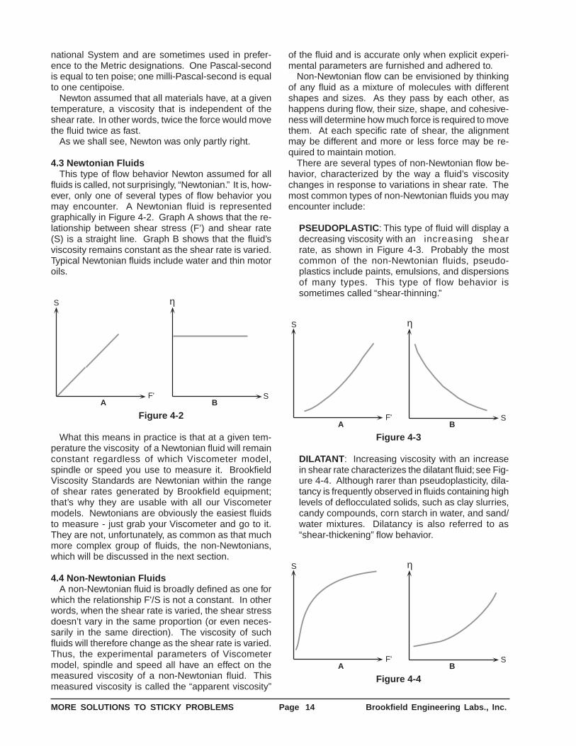
4.3 Newtonian FluidsThis type of flow behavior Newton assumed for all
fluids is called, not surprisingly, “Newtonian.” It is, how-ever, only one of several types of flow behavior youmay encounter. A Newtonian fluid is representedgraphically in Figure 4-2. Graph A shows that the re-lationship between shear stress (F’) and shear rate(S) is a straight line. Graph B shows that the fluid’sviscosity remains constant as the shear rate is varied.Typical Newtonian fluids include water and thin motoroils.
η
SBA
F'
S
Figure 4-2
What this means in practice is that at a given tem-perature the viscosity of a Newtonian fluid will remainconstant regardless of which Viscometer model,spindle or speed you use to measure it. BrookfieldViscosity Standards are Newtonian within the rangeof shear rates generated by Brookfield equipment;that’s why they are usable with all our Viscometermodels. Newtonians are obviously the easiest fluidsto measure - just grab your Viscometer and go to it.They are not, unfortunately, as common as that muchmore complex group of fluids, the non-Newtonians,which will be discussed in the next section.
4.4 Non-Newtonian FluidsA non-Newtonian fluid is broadly defined as one for
which the relationship F'/S is not a constant. In otherwords, when the shear rate is varied, the shear stressdoesn’t vary in the same proportion (or even neces-sarily in the same direction). The viscosity of suchfluids will therefore change as the shear rate is varied.Thus, the experimental parameters of Viscometermodel, spindle and speed all have an effect on themeasured viscosity of a non-Newtonian fluid. Thismeasured viscosity is called the “apparent viscosity”
of the fluid and is accurate only when explicit experi-mental parameters are furnished and adhered to.
Non-Newtonian flow can be envisioned by thinkingof any fluid as a mixture of molecules with differentshapes and sizes. As they pass by each other, ashappens during flow, their size, shape, and cohesive-ness will determine how much force is required to movethem. At each specific rate of shear, the alignmentmay be different and more or less force may be re-quired to maintain motion.
There are several types of non-Newtonian flow be-havior, characterized by the way a fluid’s viscositychanges in response to variations in shear rate. Themost common types of non-Newtonian fluids you mayencounter include:
PSEUDOPLASTIC : This type of fluid will display adecreasing viscosity with an increasing shearrate, as shown in Figure 4-3. Probably the mostcommon of the non-Newtonian fluids, pseudo-plastics include paints, emulsions, and dispersionsof many types. This type of flow behavior issometimes called “shear-thinning.”
η
SBA
F'
S
Figure 4-3
DILATANT : Increasing viscosity with an increasein shear rate characterizes the dilatant fluid; see Fig-ure 4-4. Although rarer than pseudoplasticity, dila-tancy is frequently observed in fluids containing highlevels of deflocculated solids, such as clay slurries,candy compounds, corn starch in water, and sand/water mixtures. Dilatancy is also referred to as“shear-thickening” flow behavior.
η
SBA
F'
S
Figure 4-4
MORE SOLUTIONS TO STICKY PROBLEMS Page 15 Brookfield Engineering Labs., Inc.
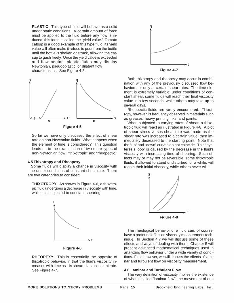
PLASTIC : This type of fluid will behave as a solidunder static conditions. A certain amount of forcemust be applied to the fluid before any flow is in-duced; this force is called the “yield value.” Tomatocatsup is a good example of this type fluid; its yieldvalue will often make it refuse to pour from the bottleuntil the bottle is shaken or struck, allowing the cat-sup to gush freely. Once the yield value is exceededand flow begins, plastic fluids may displayNewtonian, pseudoplastic, or dilatant flowcharacteristics. See Figure 4-5.
η
SBA
F'
S
f'
Figure 4-5
So far we have only discussed the effect of shearrate on non-Newtonian fluids. What happens whenthe element of time is considered? This questionleads us to the examination of two more types ofnon-Newtonian flow: “thixotropic” and “rheopectic.”
4.5 Thixotropy and RheopexySome fluids will display a change in viscosity with
time under conditions of constant shear rate. Thereare two categories to consider:
THIXOTROPY: As shown in Figure 4-6, a thixotro-pic fluid undergoes a decrease in viscosity with time,while it is subjected to constant shearing.
η
t
Figure 4-6
RHEOPEXY: This is essentially the opposite ofthixotropic behavior, in that the fluid’s viscosity in-creases with time as it is sheared at a constant rate.See Figure 4-7.
η
t
Figure 4-7
Both thixotropy and rheopexy may occur in combi-nation with any of the previously discussed flow be-haviors, or only at certain shear rates. The time ele-ment is extremely variable; under conditions of con-stant shear, some fluids will reach their final viscosityvalue in a few seconds, while others may take up toseveral days.
Rheopectic fluids are rarely encountered. Thixot-ropy, however, is frequently observed in materials suchas greases, heavy printing inks, and paints.
When subjected to varying rates of shear, a thixo-tropic fluid will react as illustrated in Figure 4-8. A plotof shear stress versus shear rate was made as theshear rate was increased to a certain value, then im-mediately decreased to the starting point. Note thatthe “up” and “down” curves do not coincide. This “hys-teresis loop” is caused by the decrease in the fluid’sviscosity with increasing time of shearing. Such ef-fects may or may not be reversible; some thixotropicfluids, if allowed to stand undisturbed for a while, willregain their initial viscosity, while others never will.
F'
S
Figure 4-8
The rheological behavior of a fluid can, of course,have a profound effect on viscosity measurement tech-nique. In Section 4.7 we will discuss some of theseeffects and ways of dealing with them. Chapter 5 willpresent advanced mathematical techniques used inanalyzing flow behavior under a wide variety of condi-tions. First, however, we will discuss the effects of lami-nar and turbulent flow on viscosity measurement.
4.6 Laminar and Turbulent FlowThe very definition of viscosity implies the existence
of what is called “laminar flow”: the movement of one
MORE SOLUTIONS TO STICKY PROBLEMS Page 16 Brookfield Engineering Labs., Inc.
layer of fluid past another with no transfer of matterfrom one to the other. Viscosity is the friction betweenthese layers.
Depending on a number of factors, there is a certainmaximum speed at which one layer of fluid can movewith relation to another, beyond which an actual transferof mass occurs. This is called “turbulence.” Moleculesor larger particles jump from one layer to another anddissipate a substantial amount of energy in the process.The net result is that a larger energy input is requiredto maintain this turbulent flow than a laminar flow atthe same velocity.
The increased energy input is manifested as anapparently greater shear stress than would beobserved under laminar flow conditions at the sameshear rate. This results in an erroneously high viscosityreading.
The point at which laminar flow evolves into turbulentflow depends on other factors besides the velocity atwhich the layers move. A material’s viscosity andspecific gravity as well as the geometry of theViscometer spindle and sample container all influencethe point at which this transition occurs.
Care should be taken to distinguish between turbu-lent flow conditions and dilatant flow behavior (seeSection 4.4). In general, dilatant materials will show asteadily increasing viscosity with increasing shear rate;turbulent flow is characterized by a relatively suddenand substantial increase in viscosity above a certainshear rate. The material’s flow behavior may beNewtonian or non-Newtonian below this point.
Due to the relatively low shear rates at which mostBrookfield Viscometers operate, it is unlikely that youwill encounter turbulent flow unless you are measur-ing viscosities lower than 15 cP with an LV series Vis-cometer or 85 cP with other models. The higher theviscosity of a fluid, the less likely it is to experienceturbulence. If turbulence is observed while measuringlow viscosity fluids, it can often be eliminated by usingthe UL Adapter accessory (see Section 2.1.5).
4.7 What Affects the Rheological Property?Viscosity data often functions as a “window” through
which other characteristics of a material may be ob-served. Viscosity is more easily measured than someof the properties that affect it, making it a valuable toolfor material characterization. Earlier in this chapterwe discussed various types of rheological behavior andhow to identify them. Having identified a particularrheological behavior in a material, you may wonderwhat this information implies about its other charac-teristics. This section, based on information gleanedfrom years of customer experience, is intended as a“tickler” to get you thinking about the mysteries yourViscometer can help you solve.
4.7.1 TemperatureOne of the most obvious factors that can have
an effect on the rheological behavior of a material is
temperature. Some materials are quite sensitive totemperature, and a relatively small variation willresult in a significant change in viscosity. Others arerelatively insensitive. Consideration of the effect oftemperature on viscosity is essential in theevaluation of materials that will be subjected totemperature variations in use or processing, suchas motor oils, greases, and hot-melt adhesives.
4.7.2 Shear RateNon-Newtonian fluids tend to be the rule rather
than the exception in the real world, making anappreciation of the effects of shear rate a necessityfor anyone engaged in the practical application ofrheological data. It would, for example, be disastrousto try to pump a dilatant fluid through a system, onlyto have it go solid inside the pump, bringing the wholeprocess to an abrupt halt. While this is an extremeexample, the importance of shear rate effects shouldnot be underestimated.
When a material is to be subjected to a varietyof shear rates in processing or use, it is essential toknow its viscosity at the projected shear rates. Ifthese are not known, an estimate should be made.Viscosity measurements should then be made atshear rates as close as possible to the estimatedvalues.
It is frequently impossible to approximateprojected shear rate values during measurementdue to these values falling outside the shear raterange of the Viscometer. In this case, it is necessaryto make measurements at several shear rates andextrapolate the data to the projected values. This isnot the most accurate method for acquiring thisinformation, but it is often the only alternativeavailable, especially when the projected shear ratesare very high. In fact, it is always advisable to makeviscosity measurements at several shear rates todetect rheological behavior that may have an effecton processing or use. Where shear rate values areunknown or not important, a sample plot of viscosityversus RPM will often suffice.
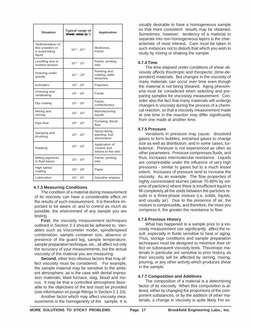
Examples of materials that are subjected to, andare affected by, wide variations in shear rate duringprocessing and use are: paints, cosmetics, liquidlatex, coatings, certain food products, and blood inthe human circulatory system. The following tableshows typical examples of varying shear rates.
MORE SOLUTIONS TO STICKY PROBLEMS Page 17 Brookfield Engineering Labs., Inc.
noitautiSfoegnarlacipyT
s(setarraehs s(setarraehs s(setarraehs s(setarraehs s(setarraehs 1- )noitacilppA
fonoitatnemideSnisredwopenif
gnidnepsusadiuqil
01 6- 01- 4- ,senicideMstniaP
oteudgnilleveLnoisnetecafrus
01 2- 01- 1- gnitnirp,stniaPskni
rednugniniarDytivarg
01 1- 01- 1
dnagnitniaPteliot,gnitaoc
sehcaelb
sredurtxE 01 0 01- 2 sremyloP
dnagniwehCgniwollaws
01 1 01- 2 sdooF
gnitaocpiD 01 1 01- 2 ,stniaPyrenoitcefnoc
dnagnixiMgnirrits
01 1 01- 3 gnirutcafunaMsdiuqil
wolfepiP 01 0 01- 3 doolb,gnipmuPwolf
dnagniyarpSgnihsurb
01 3 01- 4
,gniyd-yarpSleuf,gnitniap
noitazimota
gnibbuR01 4 01- 5 fonoitacilppA
dnasmaercniksehtotsnoitol
stnemgipgnilliMsesabdiulfni
01 3 01- 5 gnitnirp,stniaPskni
deepshgiHgnitaoc
01 5 01- 6 repaP
noitacirbuL 01 3 01- 7 senigneenilosaG
4.7.3 Measuring ConditionsThe condition of a material during measurement
of its viscosity can have a considerable effect onthe results of such measurement. It is therefore im-portant to be aware of, and to control as much aspossible, the environment of any sample you aretesting.
First , the viscosity measurement techniquesoutlined in Section 3.3 should be adhered to. Vari-ables such as Viscometer model, spindle/speedcombination, sample container size, absence orpresence of the guard leg, sample temperature,sample preparation technique, etc., all affect not onlythe accuracy of your measurements, but the actualviscosity of the material you are measuring.
Second , other less obvious factors that may af-fect viscosity must be considered. For example,the sample material may be sensitive to the ambi-ent atmosphere, as is the case with dental impres-sion materials, blast furnace, slag, blood and mu-cus. It may be that a controlled atmosphere favor-able to the objectives of the test must be provided(see information on purge fittings in Section 2.1.10).
Another factor which may affect viscosity mea-surements is the homogeneity of the sample. It is
usually desirable to have a homogeneous sampleso that more consistent results may be obtained.Sometimes, however, tendency of a material toseparate into non-homogeneous layers is the char-acteristic of most interest. Care must be taken insuch instances not to disturb that which you wish tostudy by mixing or shaking the sample.
4.7.4 TimeThe time elapsed under conditions of shear ob-
viously affects thixotropic and rheopectic (time-de-pendent) materials. But changes in the viscosity ofmany materials can occur over time even thoughthe material is not being sheared. Aging phenom-ena must be considered when selecting and pre-paring samples for viscosisty measurement. Con-sider also the fact that many materials will undergochanges in viscosity during the process of a chemi-cal reaction, so that a viscosity measurement madeat one time in the reaction may differ significantlyfrom one made at another time.
4.7.5 PressureVariations in pressure may cause: dissolved
gases to form bubbles; entrained gases to changesize as well as distribution, and in some cases, tur-bulence. Pressure is not experienced as often asother parameters. Pressure compresses fluids, andthus, increases intermolecular resistance. Liquidsare compressible under the influence of very highpressures - similar to gases but to a much lesserextent. Increases of pressure tend to increase theviscosity. As an example: The flow properties ofhighly concentrated slurries (above 70-80% by vol-ume of particles) where there is insufficient liquid tofill completely all the voids between the particles re-sults in a three-phase mixture (i.e. solids, liquids,and usually air). Due to the presence of air, themixture is compressible, and therefore, the more youcompress it, the greater the resistance to flow.
4.7.6 Previous HistoryWhat has happened to a sample prior to a vis-
cosity measurement can significantly affect the re-sult, especially in fluids sensitive to heat or aging.Thus, storage conditions and sample preparationtechniques must be designed to minimize their ef-fect on subsequent viscosity tests. Thixotropic ma-terials in particular are sensitive to prior history, astheir viscosity will be affected by stirring, mixing,pouring, or any other activity which produces shearin the sample.
4.7.7 Composition and AdditivesThe composition of a material is a determining
factor of its viscosity. When this composition is al-tered, either by changing the proportions of the com-ponent substances, or by the addition of other ma-terials, a change in viscosity is quite likely. For ex-
MORE SOLUTIONS TO STICKY PROBLEMS Page 18 Brookfield Engineering Labs., Inc.
ample, the addition of solvent to printing ink reducesviscosity of the ink; and additives of many types areused to control the rheological properties of paints.
4.7.8 Special Characteristics of Dispersionsand Emulsions
Dispersions and emulsions, which aremultiphase materials consisting of one or more solidphases dispersed in a liquid phase, can be affectedrheologically by a number of factors. In addition tomany of the factors discussed previously, charac-teristics peculiar to multiphase materials are alsosignificant to the rheology of such materials. Theseare discussed below.
One of the major characteristics to study is thestate of aggregation of the sample material. Arethe particles that make up the solid phase separateand distinct, or are they clumped together; how largeare the clumps, and how tightly are they stuck to-gether? If the clumps (flocs) occupy a large volumein the dispersion, viscosity of the dispersion will tendto be higher than if the floc volume was smaller. Thisis due to the greater force required to dissipate thesolid component of the dispersion.
When flocs are aggregated in a dispersion,reaction of the aggregates to shear can result inshear-thinning (pseudoplastic) flow. At low shearrates, the aggregates may be deformed but remainessentially intact. As the shear rate is increased,the aggregates may be broken down into individualflocs, decreasing friction and therefore viscosity (Formore information on pseudoplastic flow, see Section4.4).
If the bonds within the aggregates are extremelystrong, the system may display a yield value (seeSection 4.4 about plastic flow). The magnitude ofthe yield value depends on the force required tobreak these bonds.
If a material’s flocculated structure is destroyed
with time as it is sheared, a time-dependent type offlow behavior will be observed (see Section 4.5).
If the shear rate is decreased after destructionof some or all of the flocculated structure, thematerial’s viscosity may be lower than it previouslywas at the same shear rate. Since flocs begin tolink together after destruction, the rate at which thisoccurs affects the time required for viscosity to at-tain previous levels. If the relinking rate is high, vis-cosity will be about the same as before. If therelinking rate is low, viscosity will be lower. This re-sults in the rheological behavior called “thixotropy”(see Section 4.5).
The attraction between particles in a dispersedphase is largely dependent on the type of materialpresent at the interface between the dispersedphase and the liquid phase. This in turn affects therheological behavior of the system. Thus, the intro-duction of flocculating or deflocculating agents intoa system is one method of controlling its rheology.
Shape of the particles making up the dispersedphase is also of significance in determining asystem’s rheology. Particles suspended in a flowingmedium are constantly being rotated. If the particlesare essentially spherical, rotation can occur freely.If, however, the particles are needle or plate-shaped,the ease with which rotation can occur is lesspredictable, as is the effect of varying shear rates.
The stability of a dispersed phase is particularlycritical when measuring viscosity of a multiphasesystem. If the dispersed phase has a tendency tosettle, producing a non-homogeneous fluid, therheological characteristics of the system will change.In most cases, this means that the measured vis-cosity will decrease. Data acquired during such con-ditions will usually be erroneous, necessitating spe-cial precautions to ensure that the dispersed phaseremains in suspension.
CHAPTER 5
5.1 Advanced Methods for Rheological AnalysisAs mentioned in Chapter 1, those who follow the
Academic school of thought on viscosity measurementhave more complex needs than those who follow thePragmatic or Theoretical schools. They need viscositydata that are defined in rheological terms. This usuallyrequires a complete mathematical description of theViscometer’s operating parameters and an analysis ofthe rheological behavior of the fluid being studied.
Previous chapters have described various types offluid behavior and their relationship to measurementsmade with Brookfield Viscometers and accessories.
The Appendix details the significant operatingparameters of this equipment and presents simplifiedformulas for obtaining shear rate and shear stressvalues. However, for many this information is stillinadequate to perform the type of analysis they require.Having identified a particular flow behavior and definedit mathematically, these people need more informationto understand how the fluid will react in a certainsituation, and how to control that reaction. If is for thesepeople that this chapter is provided.
In it you will find basic formulas from which the
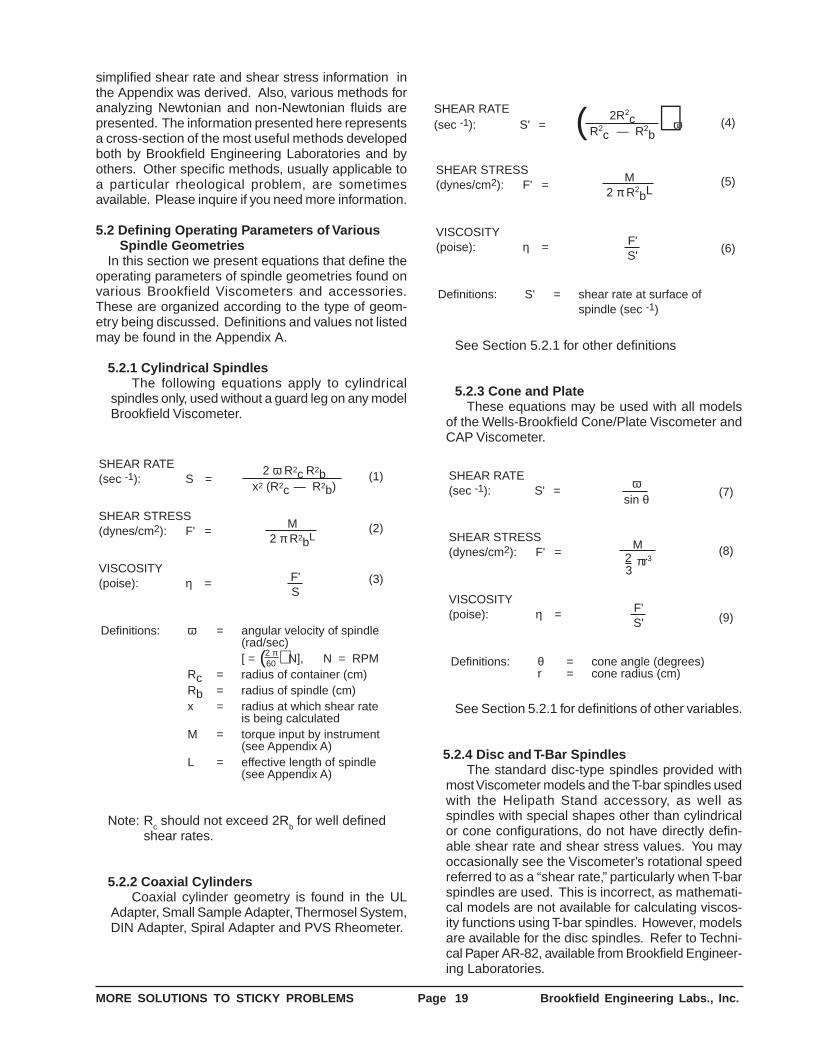
MORE SOLUTIONS TO STICKY PROBLEMS Page 19 Brookfield Engineering Labs., Inc.
simplified shear rate and shear stress information inthe Appendix was derived. Also, various methods foranalyzing Newtonian and non-Newtonian fluids arepresented. The information presented here representsa cross-section of the most useful methods developedboth by Brookfield Engineering Laboratories and byothers. Other specific methods, usually applicable toa particular rheological problem, are sometimesavailable. Please inquire if you need more information.
5.2 Defining Operating Parameters of VariousSpindle Geometries
In this section we present equations that define theoperating parameters of spindle geometries found onvarious Brookfield Viscometers and accessories.These are organized according to the type of geom-etry being discussed. Definitions and values not listedmay be found in the Appendix A.
5.2.1 Cylindrical SpindlesThe following equations apply to cylindrical
spindles only, used without a guard leg on any modelBrookfield Viscometer.
SHEAR STRESS(dynes/cm2): F' =
M2 π R2bL
2 ω R2c R2bx2 (R2c — R2b)
SHEAR RATE(sec -1): S =
VISCOSITY(poise): η = F'
S
Definitions: ω = angular velocity of spindle(rad/sec)[ = N], N = RPM
Rc = radius of container (cm)Rb = radius of spindle (cm)x = radius at which shear rate
is being calculatedM = torque input by instrument
(see Appendix A)L = effective length of spindle
(see Appendix A)
2 π60( )
(1)
(2)
(3)
Note: Rc should not exceed 2R
b for well defined
shear rates.
5.2.2 Coaxial CylindersCoaxial cylinder geometry is found in the UL
Adapter, Small Sample Adapter, Thermosel System,DIN Adapter, Spiral Adapter and PVS Rheometer.
Definitions: S' = shear rate at surface ofspindle (sec -1)
VISCOSITY(poise): η =
SHEAR STRESS(dynes/cm2): F' =
M2 π R2
bL
F'S'
SHEAR RATE(sec -1): S' = ω
2R2c
R2c — R2
b( ) (4)
(5)
(6)
See Section 5.2.1 for other definitions
5.2.3 Cone and PlateThese equations may be used with all models
of the Wells-Brookfield Cone/Plate Viscometer andCAP Viscometer.
Definitions: θ = cone angle (degrees)r = cone radius (cm)
VISCOSITY(poise): η =
SHEAR STRESS(dynes/cm2): F' =
SHEAR RATE(sec -1): S' =
ωsin θ (7)
(8)
(9)
M
3πr32
F'S'
See Section 5.2.1 for definitions of other variables.
5.2.4 Disc and T-Bar SpindlesThe standard disc-type spindles provided with
most Viscometer models and the T-bar spindles usedwith the Helipath Stand accessory, as well asspindles with special shapes other than cylindricalor cone configurations, do not have directly defin-able shear rate and shear stress values. You mayoccasionally see the Viscometer’s rotational speedreferred to as a “shear rate,” particularly when T-barspindles are used. This is incorrect, as mathemati-cal models are not available for calculating viscos-ity functions using T-bar spindles. However, modelsare available for the disc spindles. Refer to Techni-cal Paper AR-82, available from Brookfield Engineer-ing Laboratories.
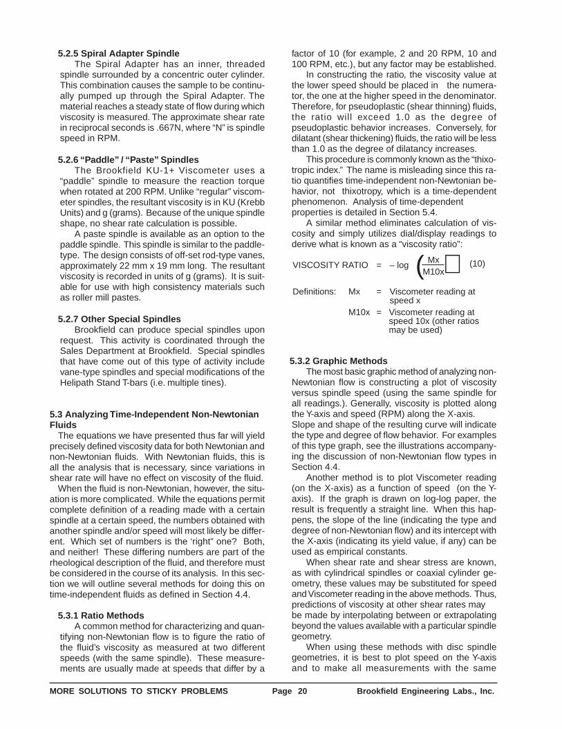
MORE SOLUTIONS TO STICKY PROBLEMS Page 20 Brookfield Engineering Labs., Inc.
5.2.5 Spiral Adapter SpindleThe Spiral Adapter has an inner, threaded
spindle surrounded by a concentric outer cylinder.This combination causes the sample to be continu-ally pumped up through the Spiral Adapter. Thematerial reaches a steady state of flow during whichviscosity is measured. The approximate shear ratein reciprocal seconds is .667N, where “N” is spindlespeed in RPM.
5.2.6 “Paddle” / “Paste” SpindlesThe Brookfield KU-1+ Viscometer uses a
“paddle” spindle to measure the reaction torquewhen rotated at 200 RPM. Unlike “regular” viscom-eter spindles, the resultant viscosity is in KU (KrebbUnits) and g (grams). Because of the unique spindleshape, no shear rate calculation is possible.
A paste spindle is available as an option to thepaddle spindle. This spindle is similar to the paddle-type. The design consists of off-set rod-type vanes,approximately 22 mm x 19 mm long. The resultantviscosity is recorded in units of g (grams). It is suit-able for use with high consistency materials suchas roller mill pastes.
5.2.7 Other Special SpindlesBrookfield can produce special spindles upon
request. This activity is coordinated through theSales Department at Brookfield. Special spindlesthat have come out of this type of activity includevane-type spindles and special modifications of theHelipath Stand T-bars (i.e. multiple tines).
5.3 Analyzing Time-Independent Non-NewtonianFluids
The equations we have presented thus far will yieldprecisely defined viscosity data for both Newtonian andnon-Newtonian fluids. With Newtonian fluids, this isall the analysis that is necessary, since variations inshear rate will have no effect on viscosity of the fluid.
When the fluid is non-Newtonian, however, the situ-ation is more complicated. While the equations permitcomplete definition of a reading made with a certainspindle at a certain speed, the numbers obtained withanother spindle and/or speed will most likely be differ-ent. Which set of numbers is the ‘right” one? Both,and neither! These differing numbers are part of therheological description of the fluid, and therefore mustbe considered in the course of its analysis. In this sec-tion we will outline several methods for doing this ontime-independent fluids as defined in Section 4.4.
5.3.1 Ratio MethodsA common method for characterizing and quan-
tifying non-Newtonian flow is to figure the ratio ofthe fluid’s viscosity as measured at two differentspeeds (with the same spindle). These measure-ments are usually made at speeds that differ by a
factor of 10 (for example, 2 and 20 RPM, 10 and100 RPM, etc.), but any factor may be established.
In constructing the ratio, the viscosity value atthe lower speed should be placed in the numera-tor, the one at the higher speed in the denominator.Therefore, for pseudoplastic (shear thinning) fluids,the ratio will exceed 1.0 as the degree ofpseudoplastic behavior increases. Conversely, fordilatant (shear thickening) fluids, the ratio will be lessthan 1.0 as the degree of dilatancy increases.
This procedure is commonly known as the “thixo-tropic index.” The name is misleading since this ra-tio quantifies time-independent non-Newtonian be-havior, not thixotropy, which is a time-dependentphenomenon. Analysis of time-dependentproperties is detailed in Section 5.4.
A similar method eliminates calculation of vis-cosity and simply utilizes dial/display readings toderive what is known as a “viscosity ratio”:
VISCOSITY RATIO = – log
Definitions: Mx = Viscometer reading atspeed x
M10x = Viscometer reading atspeed 10x (other ratiosmay be used)
MxM10x( ) (10)
5.3.2 Graphic MethodsThe most basic graphic method of analyzing non-
Newtonian flow is constructing a plot of viscosityversus spindle speed (using the same spindle forall readings.). Generally, viscosity is plotted alongthe Y-axis and speed (RPM) along the X-axis.Slope and shape of the resulting curve will indicatethe type and degree of flow behavior. For examplesof this type graph, see the illustrations accompany-ing the discussion of non-Newtonian flow types inSection 4.4.
Another method is to plot Viscometer reading(on the X-axis) as a function of speed (on the Y-axis). If the graph is drawn on log-log paper, theresult is frequently a straight line. When this hap-pens, the slope of the line (indicating the type anddegree of non-Newtonian flow) and its intercept withthe X-axis (indicating its yield value, if any) can beused as empirical constants.
When shear rate and shear stress are known,as with cylindrical spindles or coaxial cylinder ge-ometry, these values may be substituted for speedand Viscometer reading in the above methods. Thus,predictions of viscosity at other shear rates maybe made by interpolating between or extrapolatingbeyond the values available with a particular spindlegeometry.
When using these methods with disc spindlegeometries, it is best to plot speed on the Y-axisand to make all measurements with the same
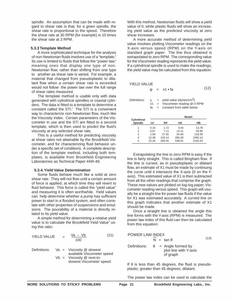
MORE SOLUTIONS TO STICKY PROBLEMS Page 21 Brookfield Engineering Labs., Inc.
spindle. An assumption that can be made with re-gard to shear rate is that, for a given spindle, theshear rate is proportional to the speed. Thereforethe shear rate at 30 RPM (for example) is 10 timesthe shear rate at 3 RPM.
5.3.3 Template MethodA more sophisticated technique for the analysis
of non-Newtonian fluids involves use of a “template.”Its use is limited to fluids that follow the “power law,”meaning ones that display one type of non-Newtonian flow, rather than shifting from one typeto another as shear rate is varied. For example, amaterial that changed from pseudoplastic to dila-tant flow when a certain shear rate is exceededwould not follow the power law over the full rangeof shear rates measured.
The template method is usable only with datagenerated with cylindrical spindles or coaxial cylin-ders. The data is fitted to a template to determine aconstant called the STI.” The STI is a convenientway to characterize non-Newtonian flow, much likethe Viscosity Index. Certain parameters of the Vis-cometer in use and the STI are fitted to a secondtemplate, which is then used to predict the fluid’sviscosity at any selected shear rate.
This is a useful method for predicting viscosityat shear rates not attainable by the Brookfield Vis-cometer, and for characterizing fluid behavior un-der a specific set of conditions. A complete descrip-tion of the template method, including both tem-plates, is available from Brookfield EngineeringLaboratories as Technical Paper #AR-49.
5.3.4. Yield Value DeterminationSome fluids behave much like a solid at zero
shear rate. They will not flow until a certain amountof force is applied, at which time they will revert tofluid behavior. This force is called the “yield value”and measuring it is often worthwhile. Yield valuescan help determine whether a pump has sufficientpower to start in a flooded system, and often corre-late with other properties of suspensions and emul-sions. The pourability of a material is directly re-lated to its yield value.
A simple method for determining a relative yieldvalue is to calculate the Brookfield Yield Value” us-ing this ratio:
YIELD VALUE Va – Vb100
Definitions: Va = Viscosity @ slowestavailable Viscometer speed
Vb = Viscosity @ next-to-slowest Viscometer speed
(11)=
With this method, Newtonian fluids will show a yieldvalue of 0, while plastic fluids will show an increas-ing yield value as the predicted viscosity at zeroshear increases.
A more accurate method of determining yieldvalue involves plotting Viscometer readings on theX-axis versus speed (RPM) on the Y-axis onstandard graph paper. The line thus obtained isextrapolated to zero RPM. The corresponding valuefor the Viscometer reading represents the yield value.If a cylindrical spindle is used to make the readings,the yield value may be calculated from this equation:
YIELD VALUE
Definitions: y = yield value (dynes/cm2)x1 = Viscometer reading @ 0 RPMfa = constant from table below
ψ = x1 • fa (12)
ModelCylindrical
Spindle LV RV HA HB
1 0.16 1.72 3.44 13.782 0.67 7.11 14.21 56.853 2.56 27.30 54.60 218.394 12.48 133.14 266.28 1065.145 25.26 269.45 538.91 2155.63
Extrapolating the line to zero RPM is easy if theline is fairly straight. This is called Bingham flow. Ifthe line is curved, as in pseudoplastic or dilatantflow, an estimate of X1 must be made by continuingthe curve until it intersects the X-axis (0 on the Y-axis). This estimated value of X1 is then subtractedfrom all the other readings that comprise the graph.These new values are plotted on log-log paper, Vis-cometer reading versus speed. This graph will usu-ally be a straight line for power law fluids if the valuefor X1 was estimated accurately. A curved line onthis graph indicates that another estimate of X1should be made.
Once a straight line is obtained the angle thisline forms with the Y-axis (RPM) is measured. Thepower law index of this fluid can then be calculatedfrom this equation:
POWER LAW INDEXN = tan θ
Definitions: θ = Angle formed byplot line with Y-axisof graph
(13)
If θ is less than 45 degrees, the fluid is pseudo-plastic; greater than 45 degrees, dilatant.
The power law index can be used to calculate the
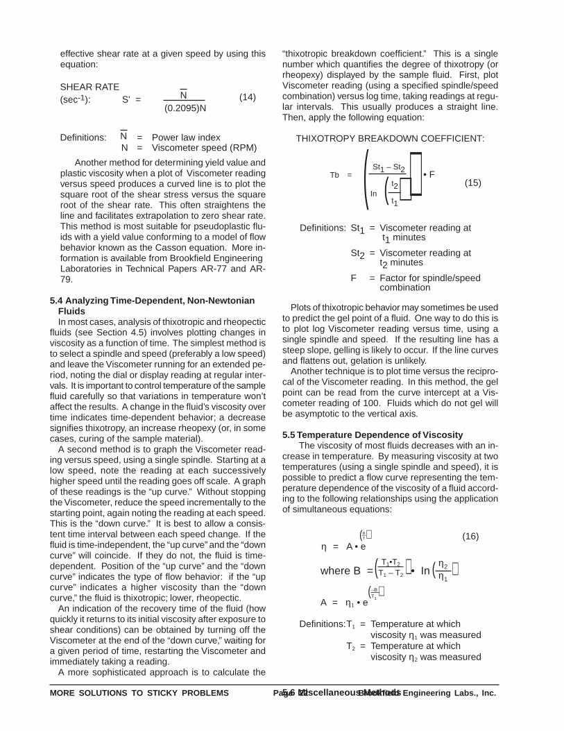
MORE SOLUTIONS TO STICKY PROBLEMS Page 22 Brookfield Engineering Labs., Inc.
effective shear rate at a given speed by using thisequation:
SHEAR RATE(sec-1): S' =
Definitions: = Power law indexN = Viscometer speed (RPM)N
N(0.2095)N
(14)
Another method for determining yield value andplastic viscosity when a plot of Viscometer readingversus speed produces a curved line is to plot thesquare root of the shear stress versus the squareroot of the shear rate. This often straightens theline and facilitates extrapolation to zero shear rate.This method is most suitable for pseudoplastic flu-ids with a yield value conforming to a model of flowbehavior known as the Casson equation. More in-formation is available from Brookfield EngineeringLaboratories in Technical Papers AR-77 and AR-79.
5.4 Analyzing Time-Dependent, Non-NewtonianFluidsIn most cases, analysis of thixotropic and rheopectic
fluids (see Section 4.5) involves plotting changes inviscosity as a function of time. The simplest method isto select a spindle and speed (preferably a low speed)and leave the Viscometer running for an extended pe-riod, noting the dial or display reading at regular inter-vals. It is important to control temperature of the samplefluid carefully so that variations in temperature won’taffect the results. A change in the fluid’s viscosity overtime indicates time-dependent behavior; a decreasesignifies thixotropy, an increase rheopexy (or, in somecases, curing of the sample material).
A second method is to graph the Viscometer read-ing versus speed, using a single spindle. Starting at alow speed, note the reading at each successivelyhigher speed until the reading goes off scale. A graphof these readings is the “up curve.” Without stoppingthe Viscometer, reduce the speed incrementally to thestarting point, again noting the reading at each speed.This is the “down curve.” It is best to allow a consis-tent time interval between each speed change. If thefluid is time-independent, the “up curve” and the “downcurve” will coincide. If they do not, the fluid is time-dependent. Position of the “up curve” and the “downcurve” indicates the type of flow behavior: if the “upcurve” indicates a higher viscosity than the “downcurve,” the fluid is thixotropic; lower, rheopectic.
An indication of the recovery time of the fluid (howquickly it returns to its initial viscosity after exposure toshear conditions) can be obtained by turning off theViscometer at the end of the “down curve,” waiting fora given period of time, restarting the Viscometer andimmediately taking a reading.
A more sophisticated approach is to calculate the
“thixotropic breakdown coefficient.” This is a singlenumber which quantifies the degree of thixotropy (orrheopexy) displayed by the sample fluid. First, plotViscometer reading (using a specified spindle/speedcombination) versus log time, taking readings at regu-lar intervals. This usually produces a straight line.Then, apply the following equation:
THIXOTROPY BREAKDOWN COEFFICIENT:
Definitions: St1 = Viscometer reading at t1 minutes
St2 = Viscometer reading att2 minutes
F = Factor for spindle/speedcombination
Tb = • FSt1 – St2
Int2
t1
(15)( ) )(
Plots of thixotropic behavior may sometimes be usedto predict the gel point of a fluid. One way to do this isto plot log Viscometer reading versus time, using asingle spindle and speed. If the resulting line has asteep slope, gelling is likely to occur. If the line curvesand flattens out, gelation is unlikely.
Another technique is to plot time versus the recipro-cal of the Viscometer reading. In this method, the gelpoint can be read from the curve intercept at a Vis-cometer reading of 100. Fluids which do not gel willbe asymptotic to the vertical axis.
5.5 Temperature Dependence of ViscosityThe viscosity of most fluids decreases with an in-
crease in temperature. By measuring viscosity at twotemperatures (using a single spindle and speed), it ispossible to predict a flow curve representing the tem-perature dependence of the viscosity of a fluid accord-ing to the following relationships using the applicationof simultaneous equations:
Definitions:T1 = Temperature at whichviscosity η1 was measured
T2 = Temperature at whichviscosity η2 was measured
(16)η = A • e
where B = • InT1•T2
T1 – T2
A = η1 • e
( ) η2
η1( )
BT( )
–BT1
( )
5.6 Miscellaneous Methods
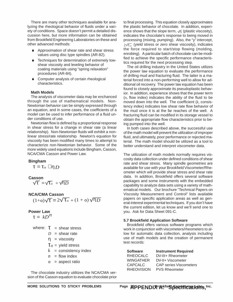
MORE SOLUTIONS TO STICKY PROBLEMS Page 23 Brookfield Engineering Labs., Inc.
There are many other techniques available for ana-lyzing the rheological behavior of fluids under a vari-ety of conditions. Space doesn’t permit a detailed dis-cussion here, but more information can be obtainedfrom Brookfield Engineering Laboratories on these andother advanced methods:
S Approximation of shear rate and shear stressvalues using disc type spindles (AR-82).
S Techniques for determination of extremely low-shear viscosity and leveling behavior ofcoating materials using “spring relaxation”procedures (AR-84).
S Computer analysis of certain rheologicalcharacteristics.
Math ModelsThe analysis of viscometer data may be enchanced
through the use of mathematical models. Non-Newtonian behavior can be simply expressed throughan equation, and in some cases, the coefficients of amodel can be used to infer performance of a fluid un-der conditions of use.
Newtonian flow is defined by a proportional responsein shear stress for a change in shear rate (a linearrelationship). Non-Newtonian fluids will exhibit a non-linear stress/rate relationship. Newton’s equation forviscosity has been modified many times to attempt tocharacterize non-Newtonian behavior. Some of themore widely used equations include Bingham, Casson,NCA/CMA Casson and Power Law.
Bingham
Casson
Power Lawτ = kDn
where: τ = shear stressD = shear rateη = viscosity
τo = yield stressk = consistency indexn = flow indexa = aspect ratio
ητ = +τo D
NCA/CMA Casson2 (1 + a)τ =(1+a) τo + Dη
τ = τo + η D
The chocolate industry utilitzes the NCA/CMA ver-sion of the Casson equation to evaluate chocolate prior
to final processing. This equation closely approximatesthe plastic behavior of chocolate. In addition, experi-ence shows that the slope term, ηD (plastic viscosity),indicates the chocolate’s response to being moved inprocessing (mixing, pumping). Also, the “y” intercept,2 τo (yield stress or zero shear viscosity), indicatesthe force required to start/stop flowing (molding,enrobing). A particular batch of chocolate can be modi-fied to achieve the specific performance characteris-tics required for the next processing step.
The oil drilling industry in the United States utilizesthe power law equation to evaluate the performanceof drilling mud and fracturing fluid. The latter is a ma-terial forced into a non-performing well to allow for ad-ditional oil recovery. The power law equation has beenfound to closely approximate its pseudoplastic behav-ior. In addition, experience shows that the power term(n, flow index) indicates the ability of the fluid to bemoved down into the well. The coefficient (k, consis-tency index) indicates low shear rate flow behavior ofthe mud once it is at the far reaches of the well. Afracturing fluid can be modified in its storage vessel toobtain the appropriate flow characteristics prior to be-ing pumped into the well.
In both cases described above, the successful useof the math model will prevent the utilization of improperfluid, and ultimately, poor performance or rejected ma-terial. The math model should be utilized as a tool tobetter understand and interpret viscometer data.
The utilization of math models normally requires vis-cosity data collection under defined conditions of shearrate and shear stress. Many spindle geometries areavailable for use with your Brookfield Viscometer/Rhe-ometer which will provide shear stress and shear ratedata. In addition, Brookfield offers several softwarepackages and some instruments with the embeddedcapability to analyze data sets using a variety of math-ematical models. Our brochure “Technical Papers onViscosity Measurement and Control” lists availablepapers on specific application areas as well as gen-eral-interest experimental techniques. If you don’t havethe current edition, let us know and we’ll send one toyou. Ask for Data Sheet 091-C.
5.7 Brookfield Application SoftwareBrookfield offers various software programs which
work in conjunction with viscometers/rheometers to al-low for automatic data collection, analysis includinguse of math models and the creation of permanenttest records:
Software Instrument RequiredRHEOCALC DV-III+ RheometerWINGATHER DV-II+ ViscometerCAPCALC CAP series ViscometersRHEOVISION PVS Rheometer
APPENDIX A: Specifications,
MORE SOLUTIONS TO STICKY PROBLEMS Page 24 Brookfield Engineering Labs., Inc.
This Appendix is intended to provide the user ofBrookfield Viscometers and accessories with all theinformation required to perform mathematical analy-ses of viscosity data acquired with this equipment. Itincludes essential dimensions, range tables and con-stants, organized by product in data sheet form. Thefollowing Brookfield Viscometers and accessories arecovered:
A.1 Dial-Reading Viscometer
A.2 Digital Viscometers/Rheometers
A.3 Wells-Brookfield Cone/Plate
Viscometers/Rheometers
A.4 Cap Viscometer
A.5 PVS Rheometer
A.6 Disc Spindles
A.7 Cylindrical Spindles
A.8 Thermosel System
A.9 Small Sample Adapter
A.10 UL Adapter
A.11 DIN Adapter
A.12 Helipath Stand
A.13 Spiral Adapter
A.14 Krebs Viscometer
Calibration Spring Torque for Standard Dial-Read-ing Viscometer and Digital Viscometer/Rheometer
LV 673.7 dyne-centimeters (full scale)RV 7187.0 dyne-centimeters (full scale)HA 14,374.0 dyne-centimeters (full scale)HB 57,496.0 dyne-centimeters (full scale)
Notes: 1. These values apply to all models withthe same prefix designation: LV re-fers to LVF, LVT, LVTD, LVT-CP,LVTDCP, etc.
Ranges, and Operating Parameters
2. For intermediate models multiply thebase spring torque by the multiplier inthe model designation: 5XLVT = 5 X673.7 = 3368.5 dyne-centimeters (fullscale). Multiplier also applies to allFactors and ranges.
3. Torque at any dial or display readingequals reading multiplied by full-scaletorque divided by 100: RVT model,reading 40; torque = (40 X 7187.0)/100 = 2874.8 dyne-cm.
A note about the terms appearing in thisAppendix:
Shear rate constants (where given) are simply mul-tiplied by the Viscometer’s rotational speed (in RPM)to obtain the shear rate (in reciprocal seconds) for thatspeed. The constants are independent of Viscometermodel, sample viscosity, or temperature.
Spindle factors are listed as constants related to theViscometers rotational speed. Divide the constant bythe speed in use to obtain the Factor for that spindle/speed/Viscometer model combination. This Factor isthen multiplied by the Viscometer’s dial or display read-ing to obtain viscosity (in centipoise).
For example: the Factor for a #2 LV spindle on anLV Viscometer is given as 300/N (Section A.1.4). TheViscometer’s rotational speed (RPM) is representedby N. If the measurement is being made at 12 RPM,the Spindle Factor is 300/12, or 25. Multiply all Vis-cometer readings made with this spindle/speed com-bination by 25 to obtain viscosity in centipoise.
Where given, Sample Chamber Diameter refers toinside diameter (I.D.). Spindle Diameters are outsidediameters (O.D.).
All dimensions are given in inches and in millime-ters (in parentheses) unless otherwise noted. Be sureto use the metric values when required for rheologicalequations.
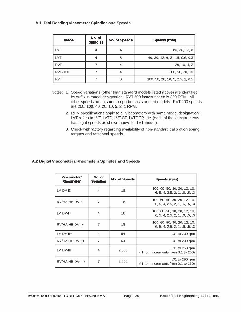
MORE SOLUTIONS TO STICKY PROBLEMS Page 25 Brookfield Engineering Labs., Inc.
ledoM ledoM ledoM ledoM ledoMfo.oN fo.oN fo.oN fo.oN fo.oNseldnipS seldnipS seldnipS seldnipS seldnipS
sdeepSfo.oN sdeepSfo.oN sdeepSfo.oN sdeepSfo.oN sdeepSfo.oN )mpr(sdeepS )mpr(sdeepS )mpr(sdeepS )mpr(sdeepS )mpr(sdeepS
FVL 4 4 6,21,03,06
TVL 4 8 3.0,6.0,5.1,3,6,21,03,06
FVR 7 4 2,4,01,02
001-FVR 7 4 01,02,05,001
TVR 7 8 5.0,1,5.2,5,01,02,05,001
Notes: 1. Speed variations (other than standard models listed above) are identifiedby suffix in model designation: RVT-200 fastest speed is 200 RPM. Allother speeds are in same proportion as standard models: RVT-200 speedsare 200, 100, 40, 20, 10, 5, 2, 1 RPM.
2. RPM specifications apply to all Viscometers with same model designation:LVT refers to LVT, LVTD, LVT-CP, LVTDCP, etc. (each of these instrumentshas eight speeds as shown above for LVT model).
3. Check with factory regarding availability of non-standard calibration springtorques and rotational speeds.
A.2 Digital Viscometers/Rheometers Spindles and Speeds
/retemocsiVretemoehR retemoehR retemoehR retemoehR retemoehR
fo.oNseldnipS seldnipS seldnipS seldnipS seldnipS
sdeepSfo.oN )mpr(sdeepS
E-VDVL 4 81,01,21,02,03,05,06,001
3.,5.,6.,1,2,5.2,4,5,6
E-VDBH/AH/VR 7 81,01,21,02,03,05,06,001
3.,5.,6.,1,2,5.2,4,5,6
+I-VDVL 4 81,01,21,02,03,05,06,001
3.,5.,6.,1,2,5.2,4,5,6
+I-VDBH/AH/VR 7 81,01,21,02,03,05,06,001
3.,5.,6.,1,2,5.2,4,5,6
+II-VDVL 4 45 mpr002ot10.
+II-VDBH/AH/VR 7 45 mpr002ot10.
+III-VDVL 4 006,2mpr052ot10.)052ot1.0morfstnemercnimpr1.(
+III-VDBH/AH/VR 7 006,2mpr052ot10.)052ot1.0morfstnemercnimpr1.(
A.1 Dial-Reading Viscometer Spindles and Speeds
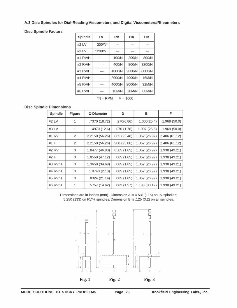
MORE SOLUTIONS TO STICKY PROBLEMS Page 26 Brookfield Engineering Labs., Inc.
A.3 Disc Spindles for Dial-Reading Viscometers and Digital Viscometers/Rheometers
Disc Spindle FactorseldnipS VL VR AH BH
VL2# *N/003 — — —
VL3# N/0021 * — — —
H/VR1# — N/001 N/002 N/008
H/VR2# — N/004 N/008 N/0023
H/VR3# — N/0001 N/0002 N/0008
H/VR4# — N/0002 N/0004 N/M61
H/VR5# — N/0004 N/0008 N/M23
H/VR6# — N/M01 N/M02 N/M08
*N = RPM M = 1000
Disc Spindle Dimensions
eldnipS erugiF retemaiD-C D E F
VL2# 1 )27.81(0737. )68.6(072. )4.52(000.1 )0.05(969.1
VL3# 1 )6.21(0794. )87.1(070. )6.52(700.1 )0.05(969.1
VR1# 2 )62.65(0512.2 )84.22(588. )79.62(260.1 )21.16(604.2
H1# 2 )62.65(0512.2 )60.32(809. )79.62(260.1 )21.16(604.2
VR2# 3 )39.64(7748.1 )56.1(5650. )79.62(260.1 )12.94(839.1
H2# 3 )21.74(0558.1 )56.1(560. )79.62(260.1 )12.94(839.1
H/VR3# 3 )96.43(8563.1 )56.1(560. )79.62(260.1 )12.94(839.1
H/VR4# 3 )3.72(8470.1 )56.1(560. )79.62(260.1 )12.94(839.1
H/VR5# 3 )41.12(4238. )56.1(560. )79.62(260.1 )12.94(839.1
H/VR6# 1 )26.41(7575. )75.1(260. )71.03(881.1 )12.94(839.1
Dimensions are in inches (mm). Dimension A is 4.531 (115) on LV spindles;5.250 (133) on RV/H spindles. Dimension B is .125 (3.2) on all spindles.
Fig. 1 Fig. 2 Fig. 3
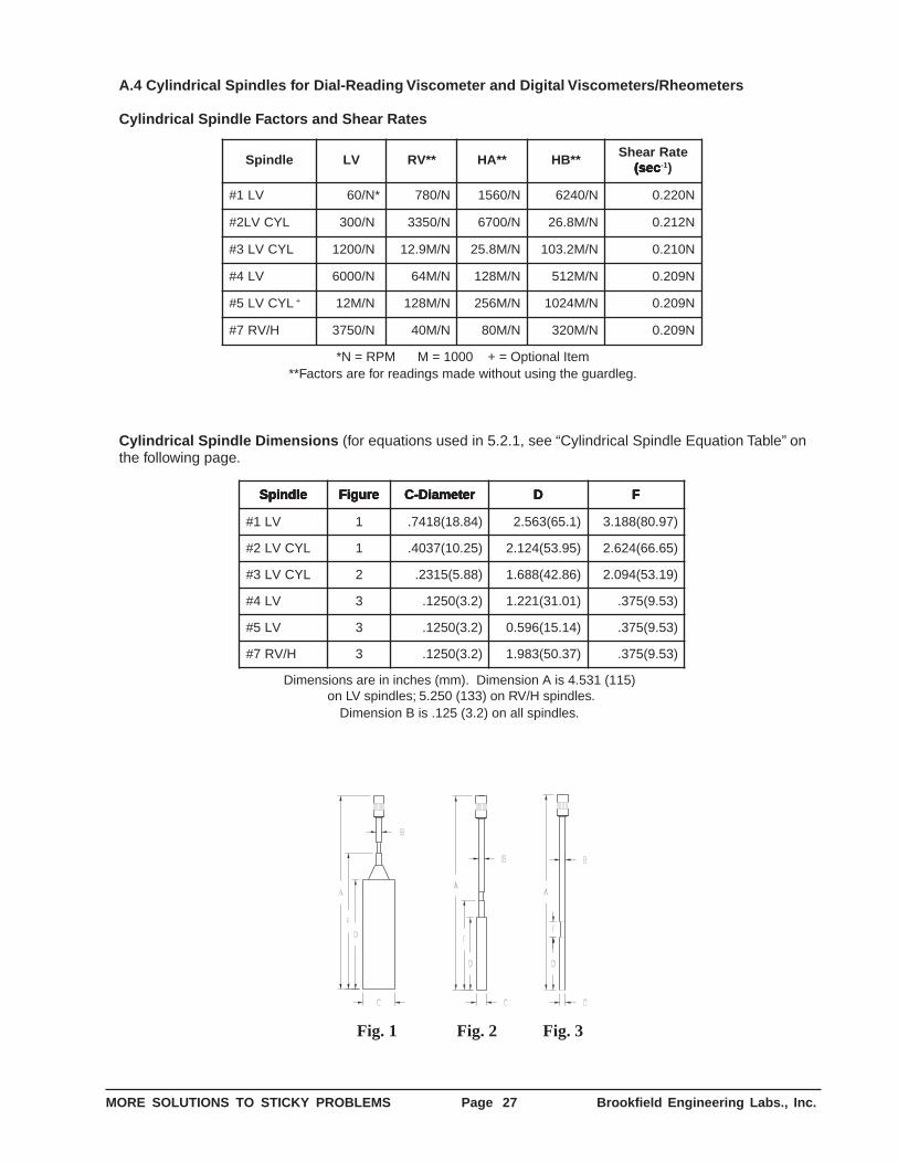
MORE SOLUTIONS TO STICKY PROBLEMS Page 27 Brookfield Engineering Labs., Inc.
A.4 Cylindrical Spindles for Dial-Reading Viscometer and Digital Viscometers/Rheometers
Cylindrical Spindle Factors and Shear Rates
eldnipS VL **VR **AH **BHetaRraehS
ces( ces( ces( ces( ces( 1- )
VL1# *N/06 N/087 N/0651 N/0426 N022.0
LYCVL2# N/003 * N/0533 N/0076 N/M8.62 N212.0
LYCVL3# N/0021 * N/M9.21 N/M8.52 N/M2.301 N012.0
VL4# N/0006 * N/M46 N/M821 N/M215 N902.0
LYCVL5# + N/M21 * N/M821 N/M652 N/M4201 N902.0
H/VR7# N/0573 * N/M04 N/M08 N/M023 N902.0
*N = RPM M = 1000 + = Optional Item**Factors are for readings made without using the guardleg.
Cylindrical Spindle Dimensions (for equations used in 5.2.1, see “Cylindrical Spindle Equation Table” onthe following page.
eldnipS eldnipS eldnipS eldnipS eldnipS erugiF erugiF erugiF erugiF erugiF retemaiD-C retemaiD-C retemaiD-C retemaiD-C retemaiD-C DDDDD FFFFF
VL1# 1 )48.81(8147. )1.56(365.2 )79.08(881.3
LYCVL2# 1 )52.01(7304. )59.35(421.2 )56.66(426.2
LYCVL3# 2 )88.5(5132. )68.24(886.1 )91.35(490.2
VL4# 3 )2.3(0521. )10.13(122.1 )35.9(573.
VL5# 3 )2.3(0521. )41.51(695.0 )35.9(573.
H/VR7# 3 )2.3(0521. )73.05(389.1 )35.9(573.
Dimensions are in inches (mm). Dimension A is 4.531 (115) on LV spindles; 5.250 (133) on RV/H spindles.
Dimension B is .125 (3.2) on all spindles.
Fig. 1 Fig. 2 Fig. 3
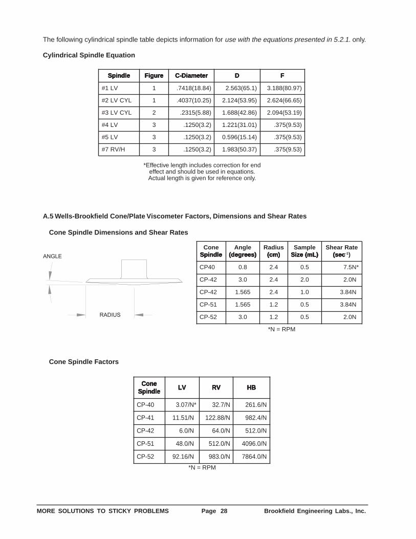
MORE SOLUTIONS TO STICKY PROBLEMS Page 28 Brookfield Engineering Labs., Inc.
The following cylindrical spindle table depicts information for use with the equations presented in 5.2.1. only.
Cylindrical Spindle Equation
eldnipS eldnipS eldnipS eldnipS eldnipS erugiF erugiF erugiF erugiF erugiF retemaiD-C retemaiD-C retemaiD-C retemaiD-C retemaiD-C DDDDD FFFFF
VL1# 1 )48.81(8147. )1.56(365.2 )79.08(881.3
LYCVL2# 1 )52.01(7304. )59.35(421.2 )56.66(426.2
LYCVL3# 2 )88.5(5132. )68.24(886.1 )91.35(490.2
VL4# 3 )2.3(0521. )10.13(122.1 )35.9(573.
VL5# 3 )2.3(0521. )41.51(695.0 )35.9(573.
H/VR7# 3 )2.3(0521. )73.05(389.1 )35.9(573.
*Effective length includes correction for endeffect and should be used in equations.Actual length is given for reference only.
A.5 Wells-Brookfield Cone/Plate Viscometer Factors, Dimensions and Shear Rates
Cone Spindle Dimensions and Shear Rates
RADIUS
ANGLE
enoCeldnipS eldnipS eldnipS eldnipS eldnipS
elgnA)seerged( )seerged( )seerged( )seerged( )seerged(
suidaR)mc( )mc( )mc( )mc( )mc(
elpmaS)Lm(eziS )Lm(eziS )Lm(eziS )Lm(eziS )Lm(eziS
etaRraehSces( ces( ces( ces( ces( 1- )
04PC 8.0 4.2 5.0 *N5.7
24-PC 0.3 4.2 0.2 N0.2 *
24-PC 565.1 4.2 0.1 N48.3 *
15-PC 565.1 2.1 5.0 N48.3 *
25-PC 0.3 2.1 5.0 N0.2 *
*N = RPM
Cone Spindle Factors
enoC enoC enoC enoC enoCeldnipS eldnipS eldnipS eldnipS eldnipS
VLVLVLVLVL VRVRVRVRVR BHBHBHBHBH
04-PC *N/70.3 N/7.23 N/6.162
14-PC N/15.11 * N/88.221 N/4.289
24-PC N/0.6 * N/0.46 N/0.215
15-PC N/0.84 * N/0.215 N/0.6904
25-PC N/61.29 * N/0.389 N/0.4687
*N = RPM
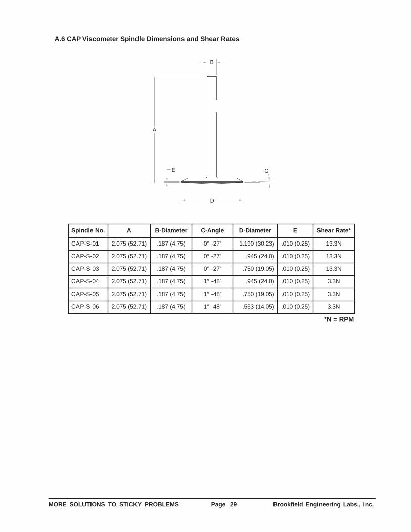
MORE SOLUTIONS TO STICKY PROBLEMS Page 29 Brookfield Engineering Labs., Inc.
A.6 CAP Viscometer Spindle Dimensions and Shear Rates
D
B
E
A
C
.oNeldnipS A retemaiD-B elgnA-C retemaiD-D E *etaRraehS
10-S-PAC )17.25(570.2 )57.4(781. '72-°0 )32.03(091.1 )52.0(010. N3.31
20-S-PAC )17.25(570.2 )57.4(781. '72-°0 )0.42(549. )52.0(010. N3.31
30-S-PAC )17.25(570.2 )57.4(781. '72-°0 )50.91(057. )52.0(010. N3.31
40-S-PAC )17.25(570.2 )57.4(781. '84-°1 )0.42(549. )52.0(010. N3.3
50-S-PAC )17.25(570.2 )57.4(781. '84-°1 )50.91(057. )52.0(010. N3.3
60-S-PAC )17.25(570.2 )57.4(781. '84-°1 )50.41(355. )52.0(010. N3.3
*N = RPM
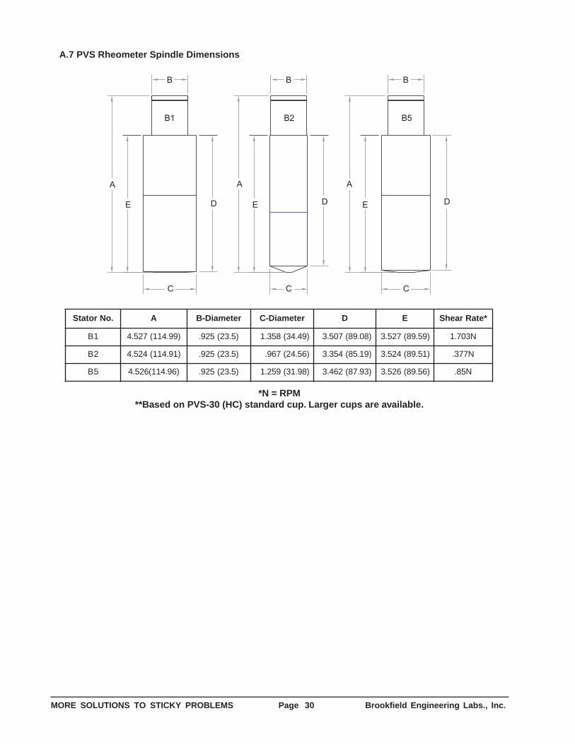
MORE SOLUTIONS TO STICKY PROBLEMS Page 30 Brookfield Engineering Labs., Inc.
A.7 PVS Rheometer Spindle Dimensions
D
B
A
C
A
B1 B2
E E
C
D E D
B5
A
C
B B
.oNrotatS A retemaiD-B retemaiD-C D E *etaRraehS
1B )99.411(725.4 )5.32(529. )94.43(853.1 )80.98(705.3 )95.98(725.3 N307.1
2B )19.411(425.4 )5.32(529. )65.42(769. )91.58(453.3 )15.98(425.3 N773.
5B )69.411(625.4 )5.32(529. )89.13(952.1 )39.78(264.3 )65.98(625.3 N58.
*N = RPM**Based on PVS-30 (HC) standard cup. Larger cups are available.
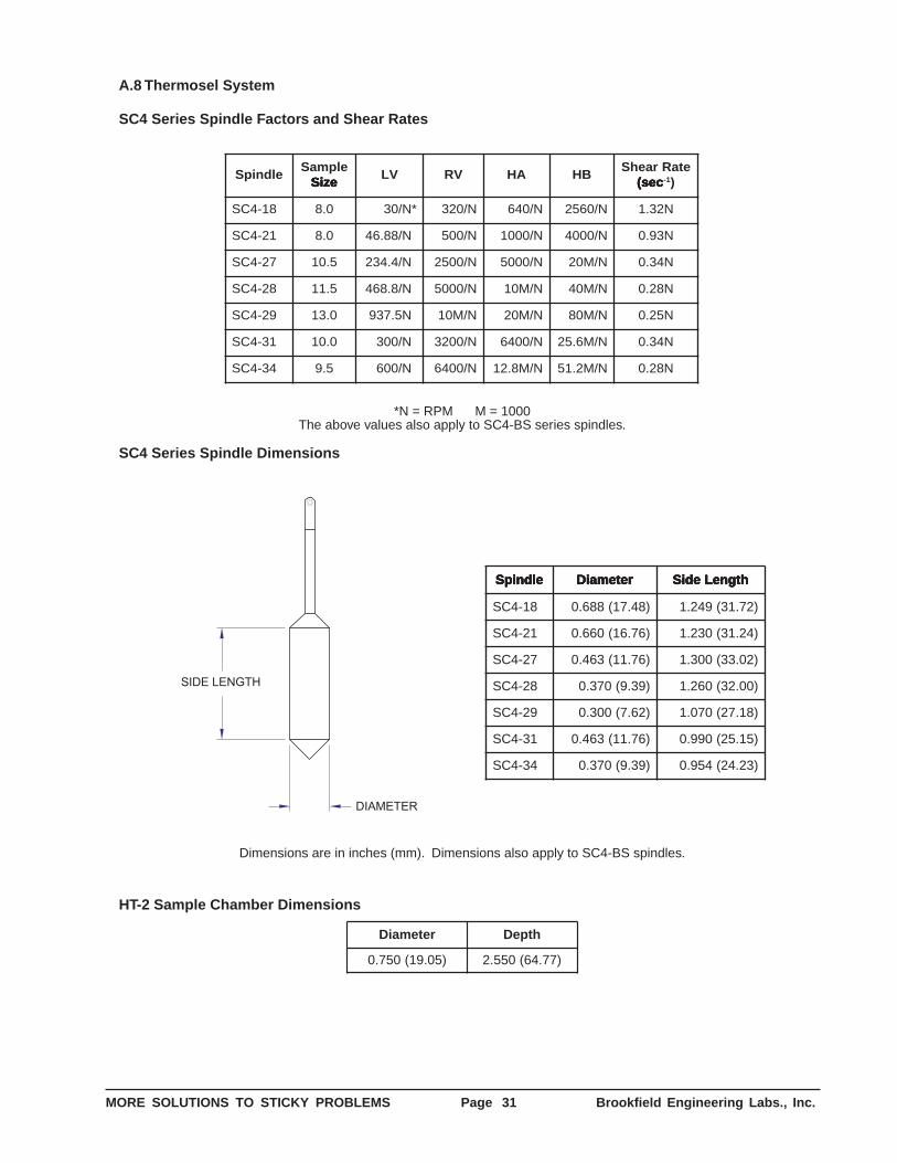
MORE SOLUTIONS TO STICKY PROBLEMS Page 31 Brookfield Engineering Labs., Inc.
A.8 Thermosel System
SC4 Series Spindle Factors and Shear Rates
eldnipSelpmaS
eziS eziS eziS eziS eziSVL VR AH BH
etaRraehSces( ces( ces( ces( ces( 1- )
81-4CS 0.8 *N/03 N/023 N/046 N/0652 N23.1
12-4CS 0.8 N/88.64 * N/005 N/0001 N/0004 N39.0
72-4CS 5.01 N/4.432 * N/0052 N/0005 N/M02 N43.0
82-4CS 5.11 N/8.864 * N/0005 N/M01 N/M04 N82.0
92-4CS 0.31 N5.739 * N/M01 N/M02 N/M08 N52.0
13-4CS 0.01 N/003 * N/0023 N/0046 N/M6.52 N43.0
43-4CS 5.9 N/006 * N/0046 N/M8.21 N/M2.15 N82.0
*N = RPM M = 1000The above values also apply to SC4-BS series spindles.
SC4 Series Spindle Dimensions
SIDE LENGTH
DIAMETER
eldnipS eldnipS eldnipS eldnipS eldnipS retemaiD retemaiD retemaiD retemaiD retemaiD htgneLediS htgneLediS htgneLediS htgneLediS htgneLediS
81-4CS )84.71(886.0 )27.13(942.1
12-4CS )67.61(066.0 )42.13(032.1
72-4CS )67.11(364.0 )20.33(003.1
82-4CS )93.9(073.0 )00.23(062.1
92-4CS )26.7(003.0 )81.72(070.1
13-4CS )67.11(364.0 )51.52(099.0
43-4CS )93.9(073.0 )32.42(459.0
Dimensions are in inches (mm). Dimensions also apply to SC4-BS spindles.
HT-2 Sample Chamber Dimensions
retemaiD htpeD
)50.91(057.0 )77.46(055.2
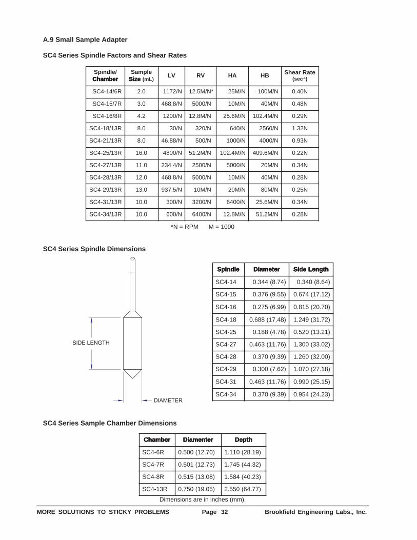
MORE SOLUTIONS TO STICKY PROBLEMS Page 32 Brookfield Engineering Labs., Inc.
A.9 Small Sample Adapter
SC4 Series Spindle Factors and Shear Rates
/eldnipSrebmahC rebmahC rebmahC rebmahC rebmahC
elpmaSeziS eziS eziS eziS eziS )Lm(
VL VR AH BH etaRraehSces( 1- )
R6/41-4CS 0.2 N/2711 *N/M5.21 N/M52 N/M001 N04.0
R7/51-4CS 0.3 N/8.864 N/0005 * N/M01 N/M04 N84.0
R8/61-4CS 2.4 N/0021 N/M8.21 * N/M6.52 N/M4.201 N92.0
R31/81-4CS 0.8 N/03 N/023 * N/046 N/0652 N23.1
R31/12-4CS 0.8 N/88.64 N/005 * N/0001 N/0004 N39.0
R31/52-4CS 0.61 N/0084 N/M2.15 * N/M4.201 N/M6.904 N22.0
R31/72-4CS 0.11 N/4.432 N/0052 * N/0005 N/M02 N43.0
R31/82-4CS 0.21 N/8.864 N/0005 * N/M01 N/M04 N82.0
R31/92-4CS 0.31 N/5.739 N/M01 * N/M02 N/M08 N52.0
R31/13-4CS 0.01 N/003 N/0023 * N/0046 N/M6.52 N43.0
R31/43-4CS 0.01 N/006 N/0046 * N/M8.21 N/M2.15 N82.0
*N = RPM M = 1000
SC4 Series Spindle Dimensions
SIDE LENGTH
DIAMETER
eldnipS eldnipS eldnipS eldnipS eldnipS retemaiD retemaiD retemaiD retemaiD retemaiD htgneLediS htgneLediS htgneLediS htgneLediS htgneLediS
41-4CS )47.8(443.0 )46.8(043.0
51-4CS )55.9(673.0 )21.71(476.0
61-4CS )99.6(572.0 )07.02(518.0
81-4CS )84.71(886.0 )27.13(942.1
52-4CS )87.4(881.0 )12.31(025.0
72-4CS )67.11(364.0 )20.33(003,1
82-4CS )93.9(073.0 )00.23(062.1
92-4CS )26.7(003.0 )81.72(070.1
13-4CS )67.11(364.0 )51.52(099.0
43-4CS )93.9(073.0 )32.42(459.0
SC4 Series Sample Chamber Dimensions
rebmahC rebmahC rebmahC rebmahC rebmahC retnemaiD retnemaiD retnemaiD retnemaiD retnemaiD htpeD htpeD htpeD htpeD htpeD
R6-4CS )07.21(005.0 )91.82(011.1
R7-4CS )37.21(105.0 )23.44(547.1
R8-4CS )80.31(515.0 )32.04(485.1
R31-4CS )50.91(057.0 )77.46(055.2
Dimensions are in inches (mm).
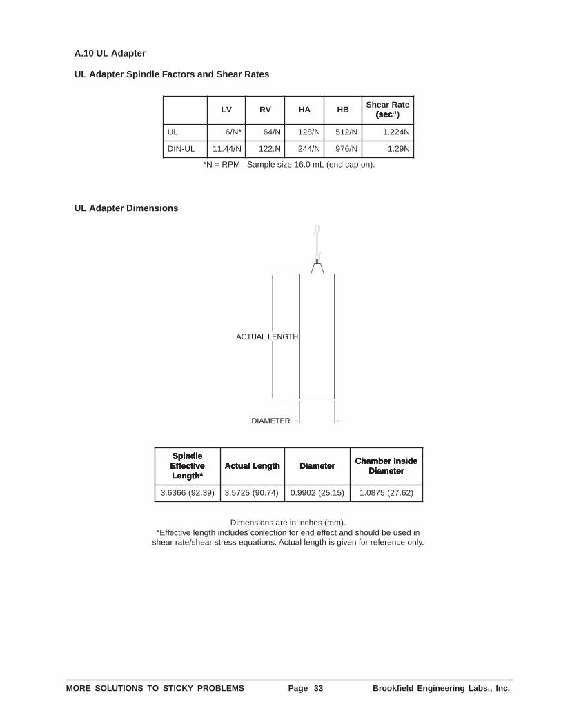
MORE SOLUTIONS TO STICKY PROBLEMS Page 33 Brookfield Engineering Labs., Inc.
A.10 UL Adapter
UL Adapter Spindle Factors and Shear Rates
VL VR AH BHetaRraehS
ces( ces( ces( ces( ces( 1- )
LU *N/6 N/46 N/821 N/215 N422.1
LU-NID N/44.11 N.221 N/442 N/679 N92.1
*N = RPM Sample size 16.0 mL (end cap on).
UL Adapter Dimensions
ACTUAL LENGTH
DIAMETER
eldnipS eldnipS eldnipS eldnipS eldnipSevitceffE evitceffE evitceffE evitceffE evitceffE*htgneL *htgneL *htgneL *htgneL *htgneL
htgneLlautcA htgneLlautcA htgneLlautcA htgneLlautcA htgneLlautcA retemaiD retemaiD retemaiD retemaiD retemaiDedisnIrebmahC edisnIrebmahC edisnIrebmahC edisnIrebmahC edisnIrebmahC
retemaiD retemaiD retemaiD retemaiD retemaiD
)93.29(6636.3 )47.09(5275.3 )51.52(2099.0 )26.72(5780.1
Dimensions are in inches (mm).*Effective length includes correction for end effect and should be used in
shear rate/shear stress equations. Actual length is given for reference only.
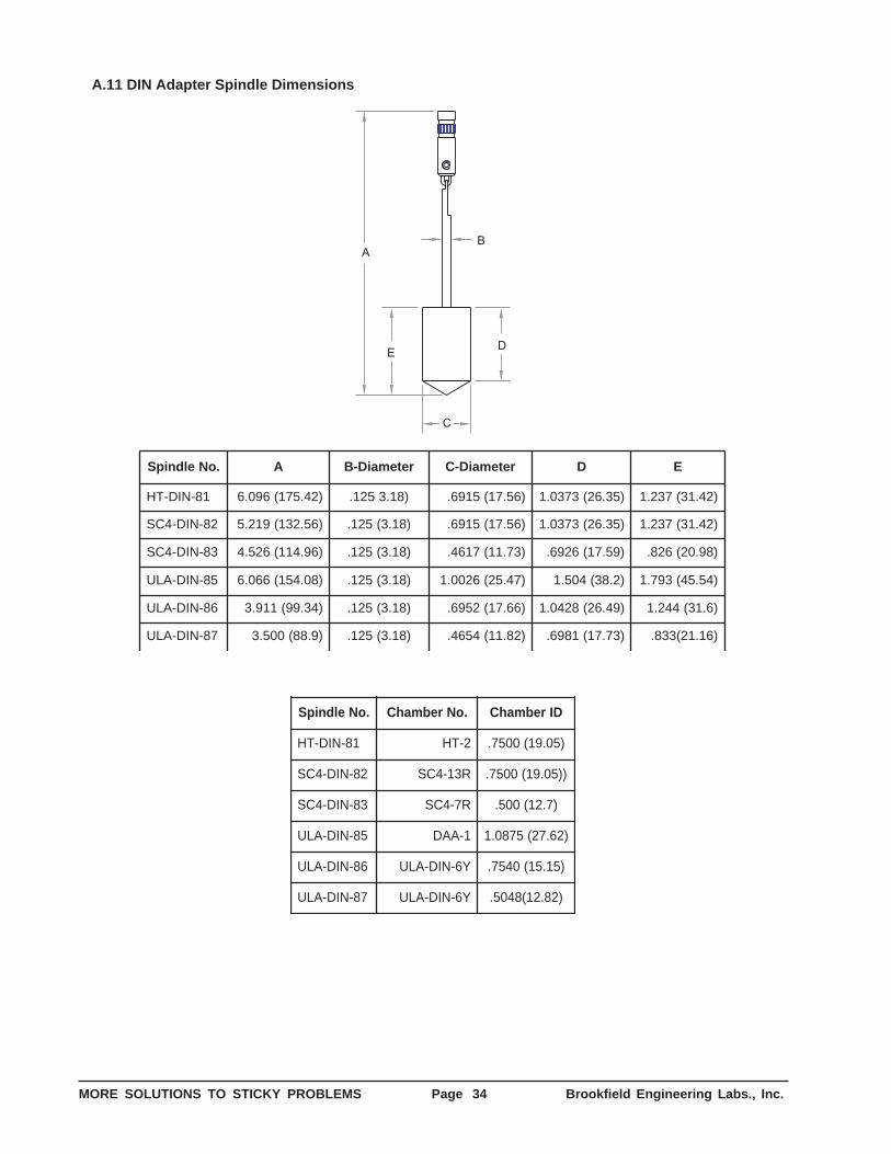
MORE SOLUTIONS TO STICKY PROBLEMS Page 34 Brookfield Engineering Labs., Inc.
A.11 DIN Adapter Spindle Dimensions
D
B
E
A
C
.oNeldnipS A retemaiD-B retemaiD-C D E
18-NID-TH )24.571(690.6 )81.3521. )65.71(5196. )53.62(3730.1 )24.13(732.1
28-NID-4CS )65.231(912.5 )81.3(521. )65.71(5196. )53.62(3730.1 )24.13(732.1
38-NID-4CS )69.411(625.4 )81.3(521. )37.11(7164. )95.71(6296. )89.02(628.
58-NID-ALU )80.451(660.6 )81.3(521. )74.52(6200.1 )2.83(405.1 )45.54(397.1
68-NID-ALU )43.99(119.3 )81.3(521. )66.71(2596. )94.62(8240.1 )6.13(442.1
78-NID-ALU )9.88(005.3 )81.3(521. )28.11(4564. )37.71(1896. )61.12(338.
.oNeldnipS .oNrebmahC DIrebmahC
18-NID-TH 2-TH )50.91(0057.
28-NID-4CS R31-4CS ))50.91(0057.
38-NID-4CS R7-4CS )7.21(005.
58-NID-ALU 1-AAD )26.72(5780.1
68-NID-ALU Y6-NID-ALU )51.51(0457.
78-NID-ALU Y6-NID-ALU )28.21(8405.
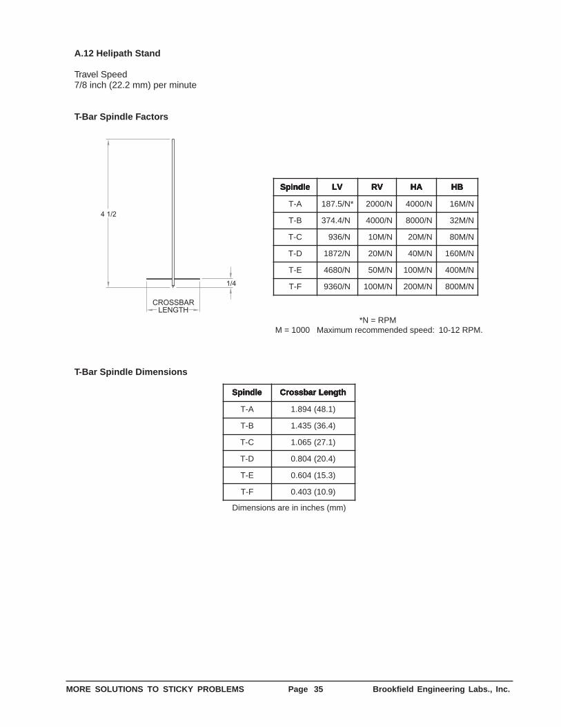
MORE SOLUTIONS TO STICKY PROBLEMS Page 35 Brookfield Engineering Labs., Inc.
A.12 Helipath Stand
Travel Speed7/8 inch (22.2 mm) per minute
T-Bar Spindle Factors
CROSSBARLENGTH
4 1/2
1/4
eldnipS eldnipS eldnipS eldnipS eldnipS VLVLVLVLVL VRVRVRVRVR AHAHAHAHAH BHBHBHBHBH
A-T *N/5.781 N/0002 N/0004 N/M61
B-T N/4.473 * N/0004 N/0008 N/M23
C-T N/639 * N/M01 N/M02 N/M08
D-T N/2781 * N/M02 N/M04 N/M061
E-T N/0864 * N/M05 N/M001 N/M004
F-T N/0639 * N/M001 N/M002 N/M008
*N = RPM M = 1000 Maximum recommended speed: 10-12 RPM.
T-Bar Spindle Dimensions
eldnipS eldnipS eldnipS eldnipS eldnipS htgneLrabssorC htgneLrabssorC htgneLrabssorC htgneLrabssorC htgneLrabssorC
A-T )1.84(498.1
B-T )4.63(534.1
C-T )1.72(560.1
D-T )4.02(408.0
E-T )3.51(406.0
F-T )9.01(304.0
Dimensions are in inches (mm)
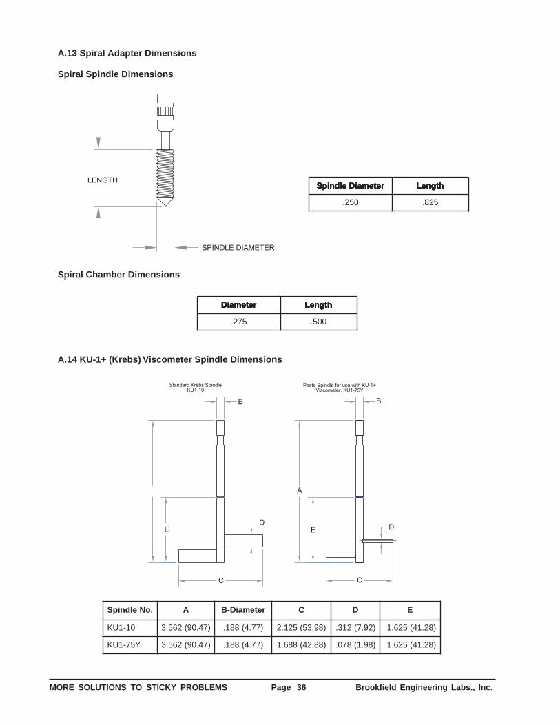
MORE SOLUTIONS TO STICKY PROBLEMS Page 36 Brookfield Engineering Labs., Inc.
A.13 Spiral Adapter Dimensions
Spiral Spindle Dimensions
LENGTH
SPINDLE DIAMETER
retemaiDeldnipS retemaiDeldnipS retemaiDeldnipS retemaiDeldnipS retemaiDeldnipS htgneL htgneL htgneL htgneL htgneL
052. 528.
Spiral Chamber Dimensions
retemaiD retemaiD retemaiD retemaiD retemaiD htgneL htgneL htgneL htgneL htgneL
572. 005.
A.14 KU-1+ (Krebs) Viscometer Spindle Dimensions
Standard Krebs SpindleKU1-10
Paste Spindle for use with KU-1+Viscometer, KU1-75Y
A
E DD
C
BB
C
E
.oNeldnipS A retemaiD-B C D E
01-1UK )74.09(265.3 )77.4(881. )89.35(521.2 )29.7(213. )82.14(526.1
Y57-1UK )74.09(265.3 )77.4(881. )88.24(886.1 )89.1(870. )82.14(526.1

MORE SOLUTIONS TO STICKY PROBLEMS Page 37 Brookfield Engineering Labs., Inc.
Viscosity of Automotive FluidLubricants Measured by theBrookfield Viscometer
D 2994-77 Methods of Testing Rubberized TarD 3232-88 Method for Measurement of
Consistency of Lubricating Greasesat High Temperatures
D 3236-88 Test Method for Apparent Viscosityof Hot Melt Adhesives and CoatingMaterials
D 3468-90 Standard Specification for Liquid-Applied Neoprene andChlorosulfonated Polyethylene Usedin Roofing and Waterproofing
D 3716-83 Method of Testing EmulsionPolymers for Use in Floor Polishes
D 3791-90 Standard Practice for Evaluating theEffects of Heat on Asphalts
D 4016-81 Test Method for Viscosity ofChemical Grouts by the BrookfieldViscometer (Laboratory Method)
D 4287-94 Standard Test Method for High-Shear Viscosity Using the ICI Cone/Plate Viscometer
D 4300-83 Test Method for Effect of MoldContamination on Permanence ofAdhesive Preparations andAdhesive Films
D 4402-87 Standard Method for ViscosityDeterminations of Unfilled AsphaltsUsing the Brookfield ThermoselApparatus
D 4889-93 Standard Test Methods forPolyurethane Raw Materials:Determination of Viscosity of Crudeor Modified Isocyanates
D 5018-89 Standard Test Method for ShearViscosity of Coal-Tar and PetroleumPitches
D 5133-90 Standard Test Method for LowTemperature, Low Shear Rate,Viscosity/Temperature Dependenceof Lubricating Oils Using aTemperature-Scanning Technique
C 965-81 Practices for Measuring Viscosity ofGlass Above the Softening Point
C 1276-94 Standard Test Method for Measuringthe Viscosity of Mold Powers Abovetheir Melting Point Using aRotational Viscometer
D 115-85 Methods of Testing Varnishes Usedfor Electrical Insulation
D 562-81 Standard Test Method forConsistency of Paints Using theStormer Viscometer
D 789-91 Test Methods for Determination ofRelative Viscosity, Melting Point, andMoisture Content of Polyamide (PA)
D 1076-88 Specification for Rubber-Concentrated, Ammonia Preserved,Creamed and Centrifuged NaturalLatex
D 1084-88 Test Methods for Viscosity ofAdhesives
D 1417-90 Methods of Testing Rubber Latices-Synthetic
D 1439-83a Methods of Testing SodiumCarboxymethyl-cellulose
D 1824-90 Test Method for Apparent Viscosityof Plastisols and Organosols at LowShear Rates by BrookfieldViscometer
D 2196-86 Test Methods for RheologicalProperties on Non-NewtonianMaterials by Rotational (Brookfield)Viscometer
D 2364-85 Standard Methods of TestingHydroxyethyl-cellulose
D 2393-86 Test Method for Viscosity of EpoxyResins and Related Components
D 2556-80 Test Method for Apparent Viscosityof Adhesives Having Shear RateDependent Flow Properties
D 2669-87 Test Method for Apparent Viscosityof Petroleum Waxes CompoundedWith Additives (Hot Melts)
D 2983-87 Test Method for Low-Temperature
APPENDIX B: ASTM Specifications
The following ASTM specifications describe the use of Brookfield Viscometers and accessories. Copies of thesedocuments are available from Brookfield upon request.
MORE SOLUTIONS TO STICKY PROBLEMS Page 38 Brookfield Engineering Labs., Inc.
APPENDIX C: References
ReferencesThe following publications are available from the publishers listed for further reading on the subject of rheology
and viscosity measurement:
VISCOSITY AND FLOW MEASUREMENTVan Wazer/Lyons/Kim/ColwellInterscience Publishers, New York, NY.
ISO standards may be purchased in the UnitedStates from:American National Standards Institute11 West 42nd Street, New York, NY. 10036Phone: 212-642-4900; Fax: 212-302-1286
Outside the United States, please contact ISO’smember in your country or:International Organization for Standardization1 rue de Varembe, 1211 Geneva 20, Switzerland
ASTM test methods are available from:ASTM1916 Race Street, Philadelphia, PA.Phone: 215-299-5400; Fax: 215-977-9679
Brookfield Engineering Laboratories maintains a li-brary of technical papers on viscosity measurementand control. Reprints are available upon request at nocharge. A current listing of available papers and anorder form are provided in the booklet, TECHNICALPAPERS ON VISCOSITY MEASUREMENT ANDCONTROL (DATA LIST 091-C).
NON-NEWTONIAN FLOW AND HEATTRANSFERA.H.P. SkellandJohn Wiley & Sons, New York, NY.
PAINT FLOW AND PIGMENT DISPERSIONSecond EditionTemple C. PattonInterscience Publishers, New York, NY.
PRINCIPLES AND APPLICATIONS OFRHEOLOGYArnold G. FredricksonPrentice-Hall Inc., Englewood Cliffs, NJ.
RHEOLOGICAL METHODS IN FOODPROCESS ENGINEERINGJames F. SteffeFreeman Press, E. Lansing, MI
RHEOLOGICAL PROPERTIES OFCOSMETICS AND TOILETRIESDennis LabaMarcel Dekker, Inc., New York, NY
VISCOMETRIC FLOWS OF NON-NEWTONIANFLUIDSColemen/Markovitz/NollSpringer-Verlag New York Inc., New York, NY.
MORE SOLUTIONS TO STICKY PROBLEMS Page 39 Brookfield Engineering Labs., Inc.
INTRODUCTION 1
CHAPTER 1 2
1.1 Why Make Rheological Measurements? 21.2 Thinking Rheo-Logically 21.3 Three Schools of Thought on Viscosity
Measurement 21.3.1 The Pragmatic School 21.3.2 The Theoretical School 21.3.3 The Academic School 3
CHAPTER 2 32.1 Equipment for Specific Situations 3
2.1.1 Viscometers 32.1.2 Spindle Geometries 32.1.3 Temperature Control 42.1.4 Small Sample Volume 42.1.5 Low Viscosity 52.1.6 High Temperature 52.1.7 Defined Shear Rate 62.1.8 High Shear Rate 62.1.9 Non-Flowing Sample Materials 62.1.10 Special Accessory Items 72.1.11 Fumes and Hazardous Locations 72.1.12 Process Control 7
CHAPTER 3 83.1 Why You Should Read This Chapter 83.2 How the Brookfield Viscometer Works 83.3 Viscosity Measurement Techniques 83.4 Viscometer Maintenance 123.5 Viscometer Troubleshooting 12
CHAPTER 4 134.1 Coming to Grips with Rheology 134.2 Viscosity 134.3 Newtonian Fluids 144.4 Non-Newtonian Fluids 144.5 Thixotropy and Rheopexy 154.6 Laminar and Turbulent Flow 154.7 What Affects the Rheological Property? 16
4.7.1 Temperature 164.7.2. Shear Rate 164.7.3 Measuring Conditions 174.7.4 Time 174.7.5 Pressure 174.7.6 Previous History 174.7.7 Composition and Additives 174.7.8 Special Characteristics of Dispersions
and Emulsions 18
CHAPTER 5 185.1 Advanced Methods for Rheological Analysis 185.2 Defining Operating Parameters of Various
Spindle Geometries 195.2.1 Cylindrical Spindles 195.2.2 Coaxial Cylinders 195.2.3 Cone and Plate 195.2.4 Disc and T-Bar Spindles 195.2.5 Spiral Adapter Spindle 205.2.6 “Paddle” / “Paste” Spindles 205.2.7 Other Special Spindles 20
5.3 Analyzing Time-Independent Non-NewtonianFluids 205.3.1 Ratio Methods 205.3.2 Graphic Methods 205.3.3 Template Method 215.3.4 Yield Value Determination 21
5.4 Analyzing Time-Dependent, Non-NewtonianFluids 22
5.5 Temperature Dependence of Viscosity 225.6 Miscellaneous Methods 235.7 Brookfield Application Software 23
APPENDIX A: Specifications, Ranges, andOperating Parameters 24
A.1 Dial-Reading Viscometer Spindle and Speeds 25A.2 Digital Viscometers/Rheometers Spindles
and Speeds 25A.3 Disc Spindles for Dial-Reading Viscometers
and Digital Viscometers/Rheometers 26A.4 Cylindrical Spindles for Dial-Reading
and Digital Viscometers/Rheometers 27A.5 Wells-Brookfield Cone/Plate Viscometer
Factors, Dimensions and Shear Rates 28A.6 CAP Viscometer Spindle Dimensions and
Shear Rates 29A.7 PVS Rheometer Spindle Dimensions and
Shear Rates 30A.8 Thermosel System 31A.9 Small Sample Adapter 32A.10 UL Adapter 33A.11 DIN Adapter Spindle Dimensions 34A.12 Helipath Stand 35A.13 Spiral Adapter DimensionsA.14 KU-1+ Viscometer Spindle Dimensions 36
APPENDIX B: ASTM Specifications 37
APPENDIX C: References 38
MORE SOLUTIONS TO STICKY PROBLEMS: TABLE OF CONTENTS