introduction to 2d and 3d computer...
TRANSCRIPT
CS447 3-1
Mastering 2D & 3D ComputerGraphics Pipelines
Introduction to 2D and 3DComputer Graphics
CS447 3-2
What are pipelines?
What are the fundamental components of
pipelines?
Example pipelines...
– ...2D graphic object pipeline
– ...3D graphic object pipeline
– ...raster pipeline
– ...bitmapped, HLHSR, illumination implications
Mastering 2D & 3D GraphicsOverview of 2D & 3D Pipelines
CS447 3-3
Overview of 2D & 3D PipelinesWhat are Pipelines?
Are the fundamental concept around which
graphics systems are based
Represent conceptual models
Describe the interaction and the flow of data
for all functions
Illustrate how the applications can create,
save, modify, draw, and display pictures

CS447 3-4
Illustrate how applications can create
pictures
Illustrate the use of functions to set up the
environment
Illustrate how the environment affects
pictures being created
Illustrate the interactions and the
relationships between functions
Overview of 2D & 3D PipelinesWhat are Pipelines?
CS447 3-5
Overview of 2D & 3D PipelinesWhat are the fundamental components?
Common components:
– Attribute Association
– Display-List Storage
– Bundled Attribute Association
– Modeling
– Viewing & Clipping
– Rendering
» with many sub-components!

CS447 3-6
Overview of 2D & 3D PipelinesAttribute Association: pipeline illustration
Primitives Associate
Attribute values stored in State Lists
Graphic objects with associated attributes; for example: Primitive Attributes,
ASF Bundle Indicators, Bundle Indices, Width/Size Specification Mode, Object Clipping Mode, Transparency, Drawing Mode, Auxiliary Colour, Pick Identifier, Transformation (initially identity), Clip Identifier, and Clip Region.
Graphic Objects
CS447 3-7
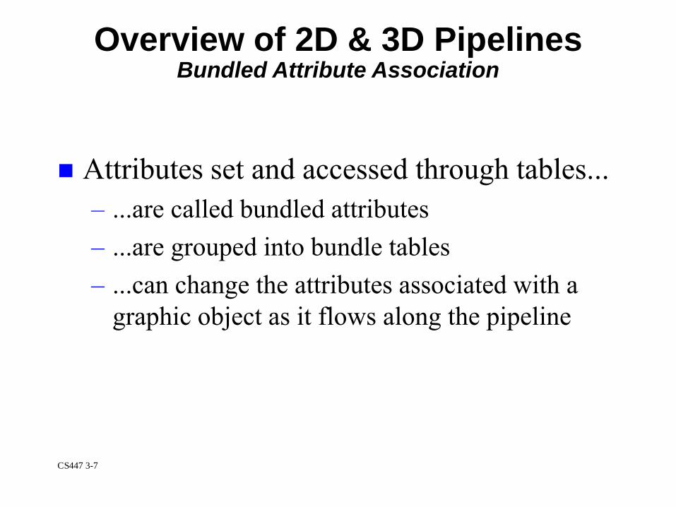
Overview of 2D & 3D PipelinesBundled Attribute Association
Attributes set and accessed through tables...
– ...are called bundled attributes
– ...are grouped into bundle tables
– ...can change the attributes associated with a
graphic object as it flows along the pipeline

CS447 3-8
Overview of 2D & 3D PipelinesDisplay-List Storage
Segment models...(e.g., CGI, GKS)
– ...describe the mechanism for saving graphic objects
Structure models...(e.g., PHIGS)
– ...describe the mechanism for saving primitive and
complex elements
Macro & procedure models...(e.g.,
POSTSCRIPT®)
– …describe the mechanism for saving macros,
procedures, & subroutines in memory for later use

CS447 3-9
Attribute
Association
Bundled
Attribute
Association
Segment
Storage
Segment
Open
No Segment Open
Segment
Transform-
ation
Associate
by
Concatenation
Objects
Being
Copied
Objects
Being
Displayed
Without
Segment
Transform
Associate Copy
Transformation
by
Concatenation
Apply
Inheritance
Filters
Attributes
Associate
Segment
Attributes of
Highlighting
and Display
Priority
One Approach to Display Lists
using segments

CS447 3-10
ApplicationProgram:
Workstation Independent
...these functions causeelements to flow along thepipeline and into centralizedstructure storage:
set polyline colour index (red)set linewidth scale factor (wide)
set linetype (dashed)polyline 3 ( )
...functions that create elements:SET POLYLINE COLOUR INDEX (Red)SET LINEWIDTH SCALE FACTOR(Wide)SET LINETYPE(Dashed)POLYLINE 3 ( )
Or, with Structures...Structure Creation: data definition process

CS447 3-11
Display Process...workstation independent
Display Process...workstation dependent
DataDefini-tionProcess
Centralized StructureStore
Modeling Viewing &View Clipping
AssociateAttributes
Associatebundledattributes
Rendering
Overview of 2D & 3D PipelinesExample: 3D graphic object pipeline
CS447 3-12
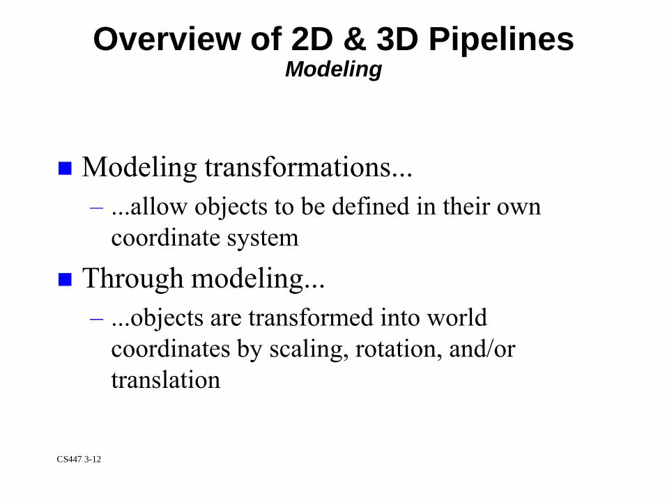
Modeling transformations...
– ...allow objects to be defined in their own
coordinate system
Through modeling...
– ...objects are transformed into world
coordinates by scaling, rotation, and/or
translation
Overview of 2D & 3D PipelinesModeling
CS447 3-13
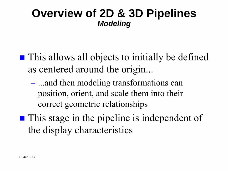
This allows all objects to initially be defined
as centered around the origin...
– ...and then modeling transformations can
position, orient, and scale them into their
correct geometric relationships
This stage in the pipeline is independent of
the display characteristics
Overview of 2D & 3D PipelinesModeling
CS447 3-14
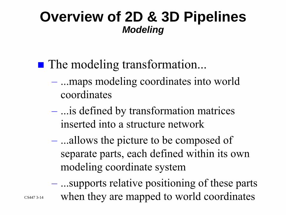
The modeling transformation...
– ...maps modeling coordinates into world
coordinates
– ...is defined by transformation matrices
inserted into a structure network
– ...allows the picture to be composed of
separate parts, each defined within its own
modeling coordinate system
– ...supports relative positioning of these parts
when they are mapped to world coordinates
Overview of 2D & 3D PipelinesModeling

CS447 3-15
Modeling Coordinates (called MC) are.
– ...3D right-handed device-independent
coordinates
– ... specified by a homogeneous
transformation matrix
When modeling transformations are not
inserted into a structure...
– ...modeling coordinates are the same as world
coordinates
Overview of 2D & 3D PipelinesModeling

CS447 3-16
2D transformations are represented by 3X3
matrices using homogeneous coordinates...
3D transformations are represented by 4x4
matrices using homogeneous coordinates in
3-space
Mastering 2D & 3D GraphicsCoordinate Spaces

CS447 3-17
What are homogeneous coordinates?
Well...instead of representing a point as
(x,y,z)...
– ...we represent it as (x,y,z,W) ...but we most
commonly refer to it as (x/W, y/W, z/W, 1)
When we transform a point to this form...
– ...it is called homogenizing
Mastering 2D & 3D GraphicsCoordinate Spaces: homogeneous coordinates
CS447 3-18
This means...that each point in 3-space is
represented by a line through the origin in
4-space!
So...homogenizing allows us to use points
that form a 3D subspace of 4-space (i.e.,
W=1)
Mastering 2D & 3D GraphicsCoordinate Spaces: homogeneous coordinates
CS447 3-19
Most graphics systems use the right-handed
coordinate system for the definition of
objects
In right-handed systems...
– ...positive rotations occur when looking from
the positive axis to the origin
– ...a 90˚ counterclockwise rotation will
transform one positive axis into the other
Mastering 2D & 3D GraphicsCoordinate Spaces: right-handed

CS447 3-20
For example, to rotate around the x axis...
...the positive rotation is from y to z
Or, to rotate around the y axis...
– ...the positive rotation is from z to x
And lastly, to rotate around the z axis...
– ...the positive rotation is from x to y
Mastering 2D & 3D GraphicsCoordinate Spaces: right-handed

CS447 3-21
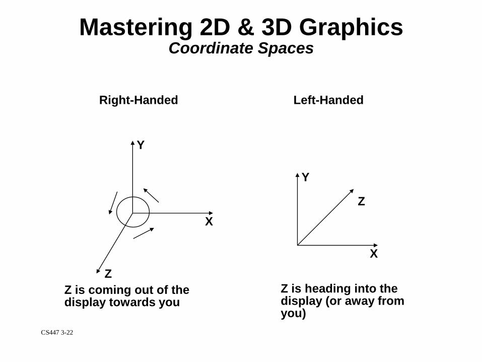
Some graphics systems use the left-handed
coordinate system for viewing objects...
– Left-handed systems may seem more natural...
...as larger z values appear further from the
operator
In left-handed systems...
– ...positive rotations occur when looking from
the positive axis to the origin
– ...a 90˚ clockwise rotation will transform one
positive axis into the other
Mastering 2D & 3D GraphicsCoordinate Spaces: left-handed
CS447 3-22
Z
X
Y
Right-Handed
Z
X
Y
Left-Handed
Z is coming out of thedisplay towards you
Z is heading into thedisplay (or away fromyou)
Mastering 2D & 3D GraphicsCoordinate Spaces
CS447 3-23
A set of vertices or 3D points belonging to
an object...
– ...can be transformed into another set of points
...using linear transformations
Mastering 2D & 3D GraphicsLinear Transformations

CS447 3-24
Translation:
1 0 0 0
[x' y' z' 1] = [x y z 1] 0 1 0 0
0 0 1 0
Tx Ty Tz 1
Translation means...
– x' = x + Tx y' = y + Ty z' = z + Tz
Mastering 2D & 3D GraphicsLinear Transformations
CS447 3-25
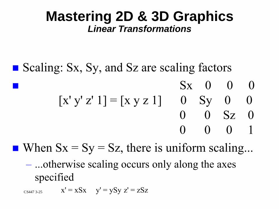
Scaling: Sx, Sy, and Sz are scaling factors
Sx 0 0 0
[x' y' z' 1] = [x y z 1] 0 Sy 0 0
0 0 Sz 0
0 0 0 1
When Sx = Sy = Sz, there is uniform scaling...
– ...otherwise scaling occurs only along the axes
specifiedx' = xSx y' = ySy z' = zSz
Mastering 2D & 3D GraphicsLinear Transformations
CS447 3-26
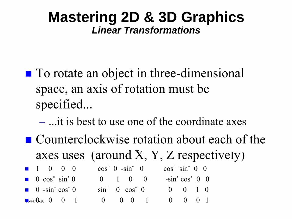
To rotate an object in three-dimensional
space, an axis of rotation must be
specified...
– ...it is best to use one of the coordinate axes
Counterclockwise rotation about each of the
axes uses (around X, Y, Z respectively) 1 0 0 0 cos˚ 0 -sin˚ 0 cos˚ sin˚ 0 0
0 cos˚ sin˚ 0 0 1 0 0 -sin˚ cos˚ 0 0
0 -sin˚ cos˚ 0 sin˚ 0 cos˚ 0 0 0 1 0
0 0 0 1 0 0 0 1 0 0 0 1
Mastering 2D & 3D GraphicsLinear Transformations

CS447 3-27
Around the Z axis, this means:
– x' = xcos˚-ysin˚
– y' = xsin˚+ycos˚
– z' = z
Mastering 2D & 3D GraphicsLinear Transformations
CS447 3-28
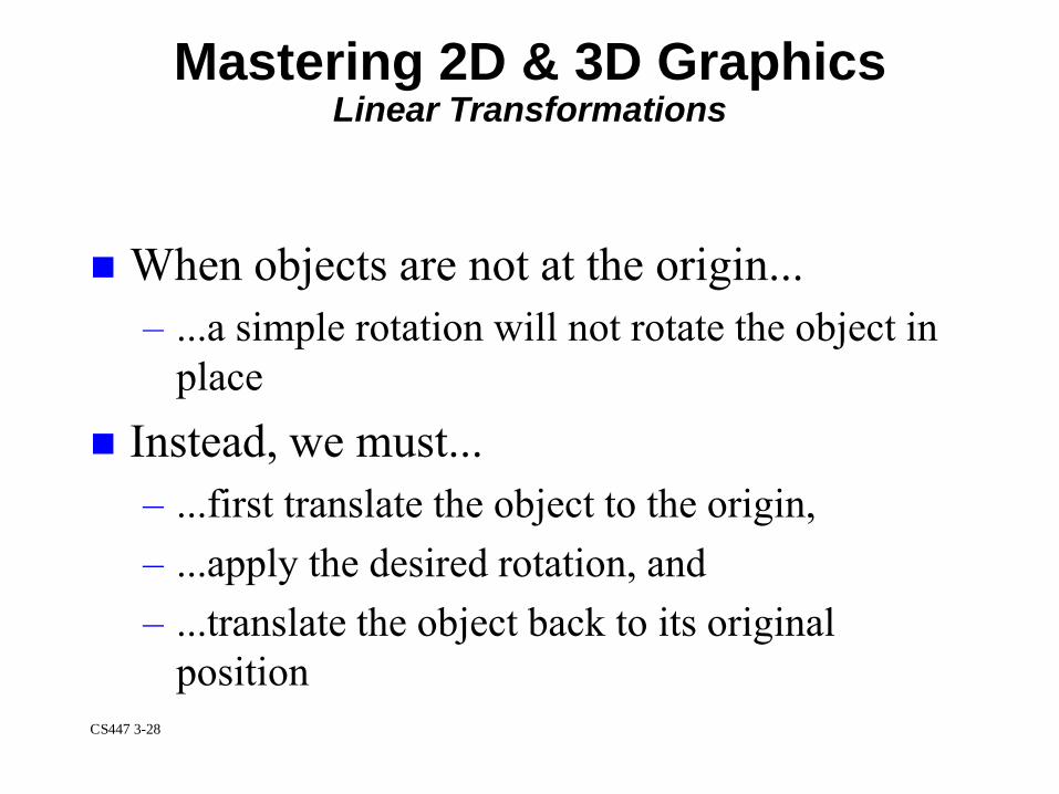
When objects are not at the origin...
– ...a simple rotation will not rotate the object in
place
Instead, we must...
– ...first translate the object to the origin,
– ...apply the desired rotation, and
– ...translate the object back to its original
position
Mastering 2D & 3D GraphicsLinear Transformations
CS447 3-29
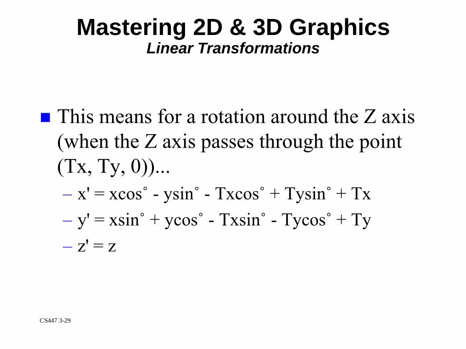
This means for a rotation around the Z axis
(when the Z axis passes through the point
(Tx, Ty, 0))...
– x' = xcos˚ - ysin˚ - Txcos˚ + Tysin˚ + Tx
– y' = xsin˚ + ycos˚ - Txsin˚ - Tycos˚ + Ty
– z' = z
Mastering 2D & 3D GraphicsLinear Transformations
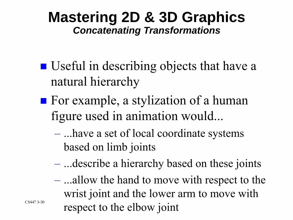
CS447 3-30
Useful in describing objects that have a
natural hierarchy
For example, a stylization of a human
figure used in animation would...
– ...have a set of local coordinate systems
based on limb joints
– ...describe a hierarchy based on these joints
– ...allow the hand to move with respect to the
wrist joint and the lower arm to move with
respect to the elbow joint
Mastering 2D & 3D GraphicsConcatenating Transformations

CS447 3-31
With Preconcatenate...
– ...the specified transformation is applied to the
object first
– ...if you preconcatenate a rotation, that rotation
will be applied to the object before the other
transformations
Current xform x New (L'=LxM)
Modeling TransformationsComposition: Concatenating Xforms

CS447 3-32
With Postconcatenate...
– ...the specified transformation is applied to the
object after the current existing local
transformation
New x Current Xform (L'=MxL)
Modeling TransformationsComposition: Concatenating Xforms
CS447 3-33
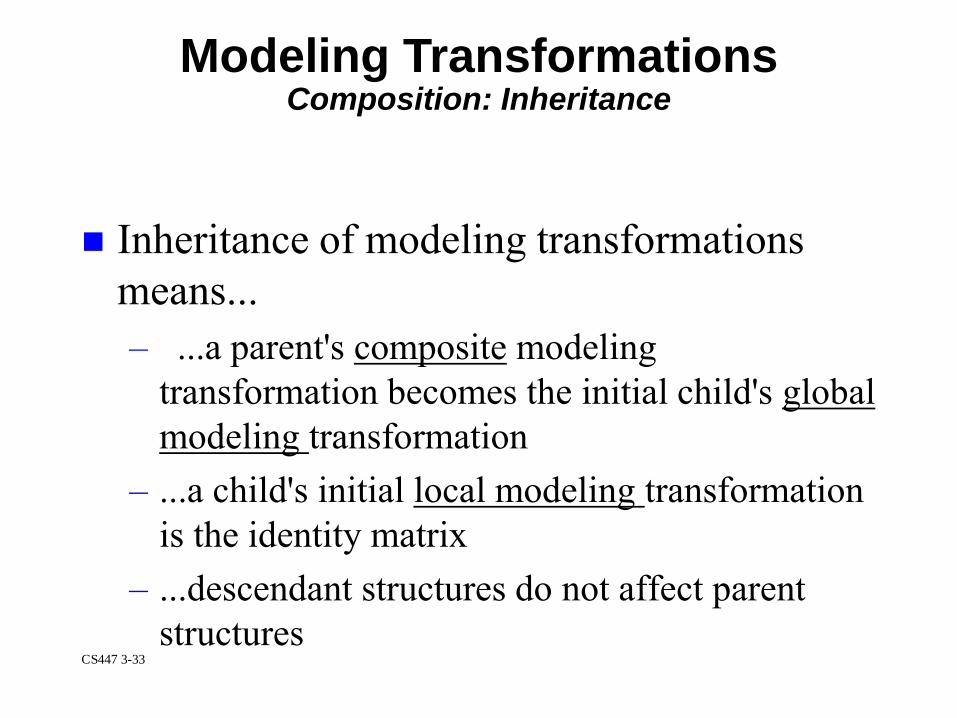
Inheritance of modeling transformations
means...
– ...a parent's composite modeling
transformation becomes the initial child's global
modeling transformation
– ...a child's initial local modeling transformation
is the identity matrix
– ...descendant structures do not affect parent
structures
Modeling TransformationsComposition: Inheritance

CS447 3-34
Modifications...
– to the global transformation only have effect
within the structure in which they are
encountered
– This allows structure hierarchies to be built
with movable parts...
– ...since the motion of the parent structure is
passed to its children via inheritance of the
composite modeling transformation, the parts
are kept connected
Modeling TransformationsComposition: Inheritance
CS447 3-35
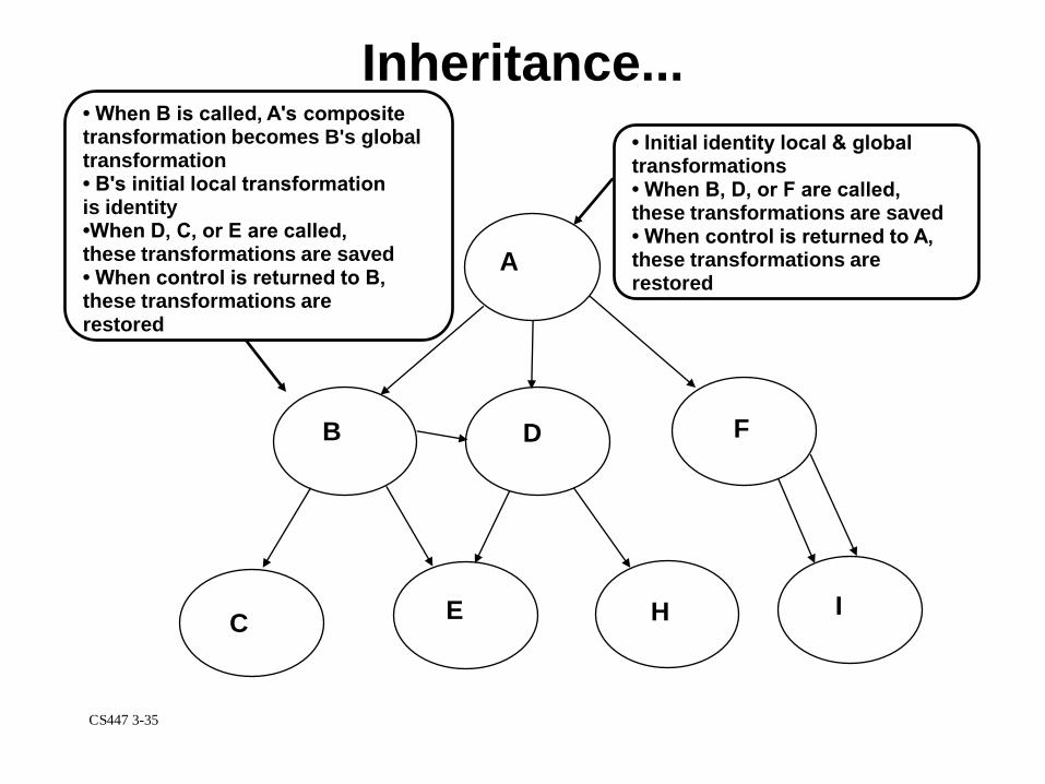
Inheritance...
A
B
C
D
E
F
H I
• Initial identity local & globaltransformations• When B, D, or F are called,these transformations are saved• When control is returned to A,these transformations arerestored
• When B is called, A's composite transformation becomes B's global transformation• B's initial local transformationis identity•When D, C, or E are called,these transformations are saved• When control is returned to B,these transformations arerestored
CS447 3-36
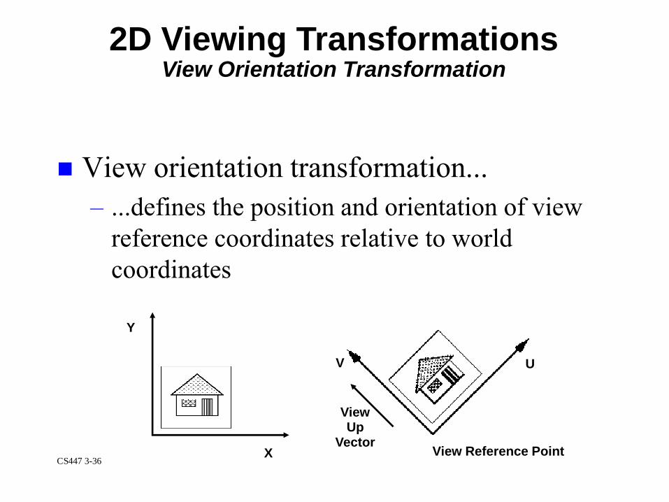
View orientation transformation...
– ...defines the position and orientation of view
reference coordinates relative to world
coordinates
2D Viewing TransformationsView Orientation Transformation
Y
X
V U
View Reference Point
ViewUp
Vector
CS447 3-37
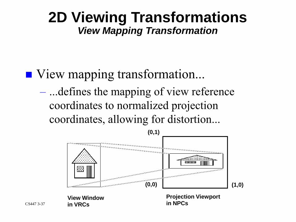
View mapping transformation...
– ...defines the mapping of view reference
coordinates to normalized projection
coordinates, allowing for distortion...
2D Viewing TransformationsView Mapping Transformation
(0,0)
(0,1)
(1,0)
View Windowin VRCs
Projection Viewportin NPCs

CS447 3-38
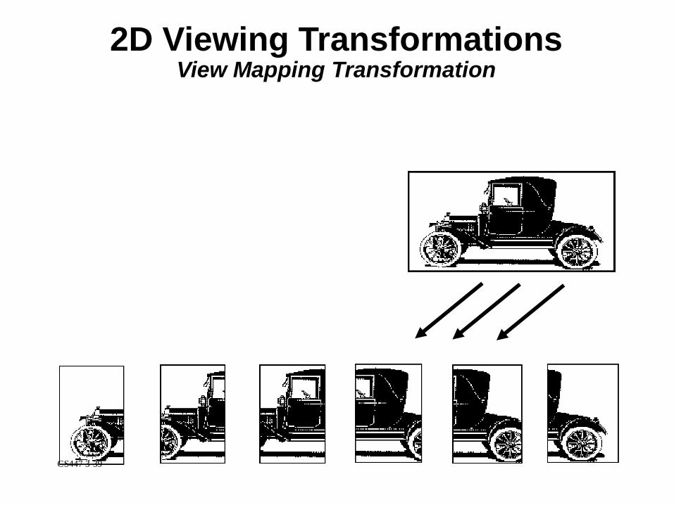
Allows dynamic horizontal and vertical
panning...
– ...by continuously adding to both sides of the
view window, or
– ...by changing the view reference point and
leaving the view window unchanged
Remember, panning is achieved by
changing the window location!
2D Viewing TransformationsView Mapping Transformation
CS447 3-39
2D Viewing TransformationsView Mapping Transformation
CS447 3-40
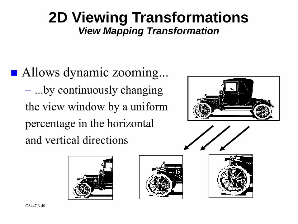
Allows dynamic zooming...
– ...by continuously changing
the view window by a uniform
percentage in the horizontal
and vertical directions
2D Viewing TransformationsView Mapping Transformation

CS447 3-41
Allows dynamic rotation...
– ...by continuously changing the
view up vector
– The effect is as if you were
rotating a camera used to view
your picture
2D Viewing TransformationsView Mapping Transformation
CS447 3-42
Overview of 2D & 3D Pipelines3D Viewing & Clipping
Three operations are associated with 3D
viewing...
– ...view orientation
– ...view mapping ...XYZ clipping
View orientation...
– ...maps world coordinates to view reference
coordinates
– ...transforms and defines the position and
orientation of the VRCs relative to world
coordinates
CS447 3-43
Overview of 2D & 3D Pipelines3D Viewing & Clipping
View mapping...
– ...maps view reference coordinates to
normalized projection coordinates
...specifies a 3D volume of VRC to be mapped
to a 3D volume of NPC (a unit cube extending
from 0.0 to 1.0 in X,Y,Z)
XYZ clipping...
– ...is performed on the XY boundary (or clip
rectangle), and front and back planes

CS447 3-44
Overview of 2D & 3D PipelinesRendering
Is the general process for changing a 2D or
3D graphic object to a shaded 2D projection
onto a drawing surface
Rendering involves...
– ...setting up data structures for polygon mesh
models to ensure that they will contain all of
the information required in the shading process
CS447 3-45
Overview of 2D & 3D PipelinesRendering
Rendering also involves...
– ...setting up data structures for polygon mesh
models to ensure that they will contain all of
the information required in the shading process
– ...culling back-facing polygons (3D Only)
– ...applying a hidden surface removal
algorithm(3D Only) ...scan converting or
rasterizing polygons: converting an object's
vertices into a set of pixel coordinates &
shading

CS447 3-46
Apply
VDC-to-Device
Mapping
Render
Abstractly
Apply
Associated
Transformation
Apply
Associated
Clipping
Apply Drawing
Surface
Clipping
Render
Physically
Apply Colour
Table
Drawing Surface
Point Set in Real-Valued
VDC Space, with associated:
Transformation, Clip Indicator,
Clip Rectangle,
Object Clipping Mode
Colour Attributes,
Transparency, and
Drawing Mode
Point Set in
Real-Valued
DC Space with
associated:
Colour Attributes,
Transparency, and
Drawing Mode
Device-Specific
Rendered Picture
Representation
with associated:
Colour value
Apply Implicit
Display
Transformation
Drawing Surface
Clip Rectangle
and Clip Indicator
Colour
Table
Echo
Overview of 2D & 3D PipelinesExample: 2D graphic object pipeline
Viewing andRendering