introduction to aluminum as a structural material
TRANSCRIPT

Introduction to Aluminum as
a Structural Material
Randy Kissell, P.E.
Trinity Consultants

Learning Outcomes
Know the major aluminum alloy groups
and their uses
Know the principal structural properties of
aluminum
Become proficient in designing aluminum
structural members and connections
Designing Aluminum Structures 2
Designing Aluminum Structures 3
Course Outline
1 Overview
2 Alloys and tempers
3 Products
4 Material properties
5 Structural design overview
Designing Aluminum Structures 4
1. Overview
Examples of aluminum structures
Aluminum’s main attributes
Sources of information

Designing Aluminum Structures 5
Examples of Aluminum Structures
Curtain walls and storefronts
Roofing and canopies
Space frames
Tanks and vessels (corrosive & cryogenic)
Portable structures (scaffolding, ladders)
Highway products (signs, light poles, bridge rail)

Designing Aluminum Structures 6
Cira Center Curtain Wall
courtesy of Larson Engr.
Designing Aluminum Structures 7
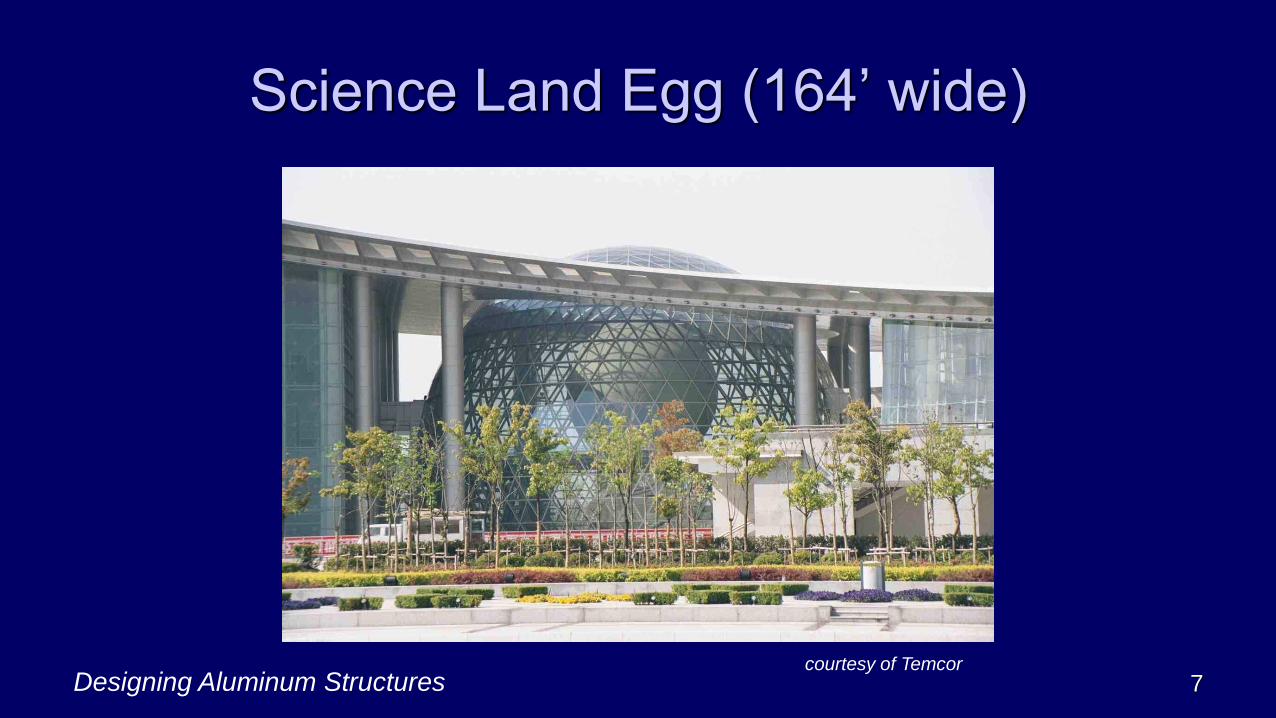
Science Land Egg (164’ wide)
courtesy of Temcor
Designing Aluminum Structures 8
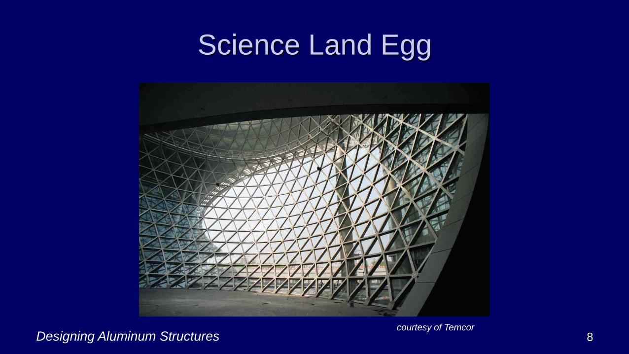
Science Land Egg
courtesy of Temcor

Designing Aluminum Structures 9
Aluminum’s Main Attributes
Formability
High strength-to-weight ratio
Corrosion resistance
Better strength, ductility at low temperature
Low modulus of elasticity (10,000 ksi)
High electrical and thermal conductivity
Low melting point (1200oF)
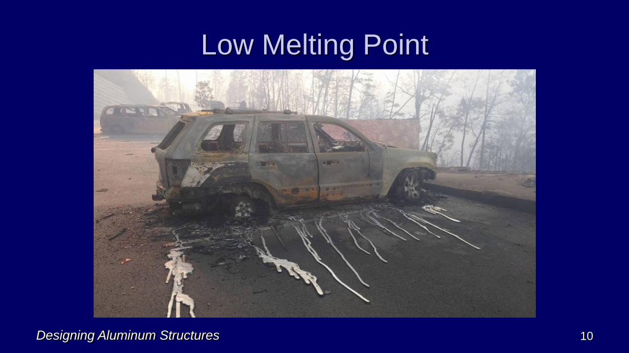
Low Melting Point
Designing Aluminum Structures 10
Designing Aluminum Structures 11
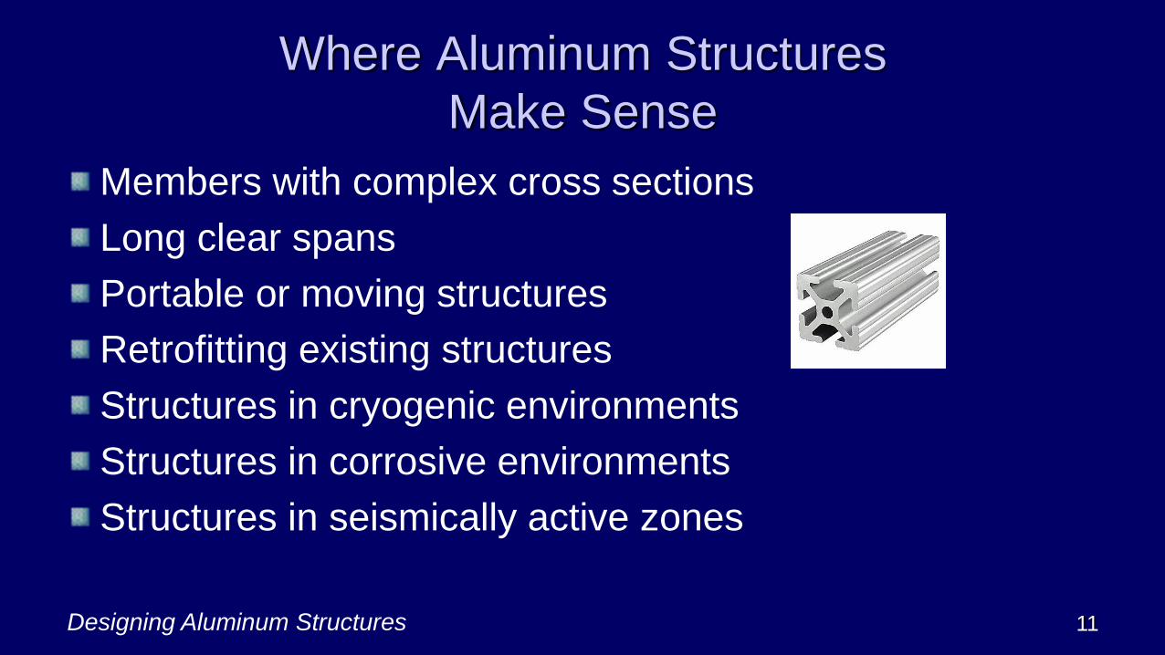
Where Aluminum Structures
Make Sense
Members with complex cross sections
Long clear spans
Portable or moving structures
Retrofitting existing structures
Structures in cryogenic environments
Structures in corrosive environments
Structures in seismically active zones
Designing Aluminum Structures 12
Founded in 1933, its 120 members include the major US
producers
AA writes most standards on aluminum; has worldwide
influence
Contact: www.aluminum.org
1400 Crystal Drive, Suite 430
Arlington, VA 22202
703-358-2960; pubs 480-779-6259
The Aluminum Design Manual
Designing Aluminum Structures 13

Designing Aluminum Structures 14
Aluminum Design Manual (ADM)
Issued every 5 years; latest is 2020
Prior editions: 1994, 2000, 2005, 2010, 2015
1st ed (1994) was compilation of several AA pubs
previously issued separately; most importantly, the
Specification for Aluminum Structures (SAS)Errata: http://aluminum.org/resources/industry-standards

Designing Aluminum Structures 15
Aluminum Design Manual Contents
The Aluminum Design Manual (ADM)
Part I – Specification for Aluminum Structures
Part II – Commentary
Part III – Design Guide
Part IV – Material Properties
Part V – Section Properties

Designing Aluminum Structures 16
Aluminum Design Manual Contents
The Aluminum Design Manual (ADM)
Part VI – Design Aids
Part VII – Illustrative Examples
Part VIII – Guidelines for Aluminum Sheet
Metal Work in Building Construction
Part IX – Code of Standard Practice for
Fabricating and Erecting Structural Aluminum
Designing Aluminum Structures 17
Specification for Aluminum Structures (SAS)
The Specification for Aluminum Structures is Part I of the
Aluminum Design Manual
SAS is also called “the Aluminum Specification”
Adopted in IBC (and previously by BOCA, UBC, SBC)
It’s the source of all aluminum structural design
requirements in the US

Designing Aluminum Structures 18
Specification for Aluminum Structures (SAS)
2010 edition was a major rewrite
It’s a unified Specification, with both:
Allowable Strength Design (ASD)▪ For buildings and bridges
Load and Resistance Factor Design (LRFD)▪ For buildings only
▪ Load factors from ASCE 7 (= 1.2D + 1.6L …)
▪ Every edition since 1994 has had LFRD

Designing Aluminum Structures 19
2020 Specification for
Aluminum Structures (SAS)
A. General Provisions
B. Design Requirements
C. Design for Stability*
D. Design of Members for Tension
E. Design of Members for Compression
F. Design of Members for Flexure
G. Design of Members for Shear
H. Design of Members for Combined Forces and Torsion
J. Design of Connections

Designing Aluminum Structures 20
2020 Specification for
Aluminum Structures (SAS)
L. Design for Serviceability*
M. Fabrication and Erection
N. Quality Control and Quality Assurance**
Appendices
1. Testing
3. Design for Fatigue
4. Design for Fire Conditions*
5. Evaluation of Existing Structures*
6. Member Stability Bracing*
*New in 2010; **New in 2015
Designing Aluminum Structures 21
2. Alloys and Tempers
Wrought alloy designation system
Aluminum temper designation system
Material specifications
Designing Aluminum Structures 22
Aluminum Isn’t Just One Thing
Like other metals, aluminum comes in many alloys
Alloy = material with metallic properties, composed of 2 or
more elements, of which at least one is a metal
Different aluminum alloys can have very different
properties
Alloying elements are usually < 5%

Designing Aluminum Structures 23
Wrought Alloy Designation System
Number Main Alloy Strength Corrosion
1xxx > 99% Al Fair Excellent
2xxx Cu High Fair
3xxx Mn Fair Good
4xxx Si Good Good
5xxx Mg Good Good
6xxx Mg Si Good Good
7xxx Zn High Fair
8xxx others

Designing Aluminum Structures 24
Wrought Alloy Key
1st digit denotes main alloying element
3rd and 4th digits are sequentially assigned
2nd digit denotes a modification
Example:
2319 = AlCu alloy (2xxx) modification on 2219
2319 composition is identical to 2219 except slightly more Ti
(grain refiner to improve weld strength); both have 6.3% Cu

Designing Aluminum Structures 25
1xxx Alloys (pure Al)
Common uses:
Electrical conductors
Corrosive environments
Examples
1060 (99.60% aluminum)
1100 (99.00% aluminum)
Pro: corrosion resistant, good conductors
Con: Not very strong
Designing Aluminum Structures 26
2xxx Alloys (Al-Cu)
Common Uses
Aircraft parts, skins
Fasteners
Example
2024
Pro: Strong
Con: Not very corrosion resistant; hard to weld when Cu
is about 1 to 5%

Designing Aluminum Structures 27
3xxx Alloys (Al-Mn)
Common Uses
Roofing and siding
Gutters and downspouts
Examples
3003, 3004, 3105
Pro: Formable, good corrosion resistance
Con: Not that strong

Designing Aluminum Structures 28
4xxx Alloys (Al-Si)
Common Uses
Welding and brazing filler metal
Example
4043
Pro: Flows well
Con: Lower ductility

Designing Aluminum Structures 29
5xxx Alloys (Al-Mg)
Common Uses
Marine applications
Welded plate structures
Examples
5052, 5083
Pro: Strong, even when welded
Con: Hard to extrude; those with 3%+ Mg can have
corrosion resistance issues

5xxx Alloys
Designing Aluminum Structures 30
0
10
20
30
40
50
60
0 1 2 3 4 5
Te
nsile
Str
en
gth
(ksi)
Mg content %
Annealed Tensile Strengths vs Mg Content
Ftu
Fty
5456
5059
50055050
50525083
5086
5154
exfoliation
corrosion
issues
1060
Ftu
Fty
Designing Aluminum Structures 31
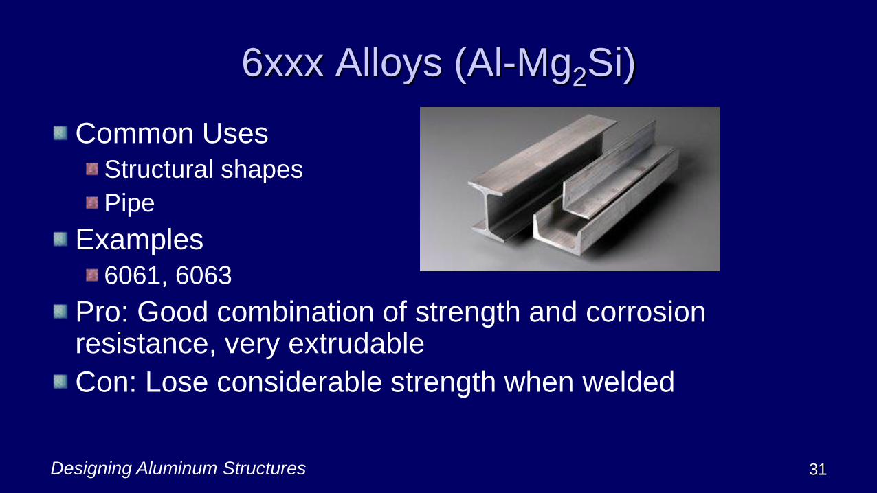
6xxx Alloys (Al-Mg2Si)
Common Uses
Structural shapes
Pipe
Examples
6061, 6063
Pro: Good combination of strength and corrosion resistance, very extrudable
Con: Lose considerable strength when welded

Designing Aluminum Structures 32
7xxx Alloys (Al-Zn)
Common Uses
Aircraft parts
Two classes
With copper (example: 7075)
Without copper (example: 7005)
Pro: Very strong (7075-T6 Ftu = 80 ksi)
Con: Not very corrosion resistant;
hard to arc weld (except those w/ no Cu)
Designing Aluminum Structures 33
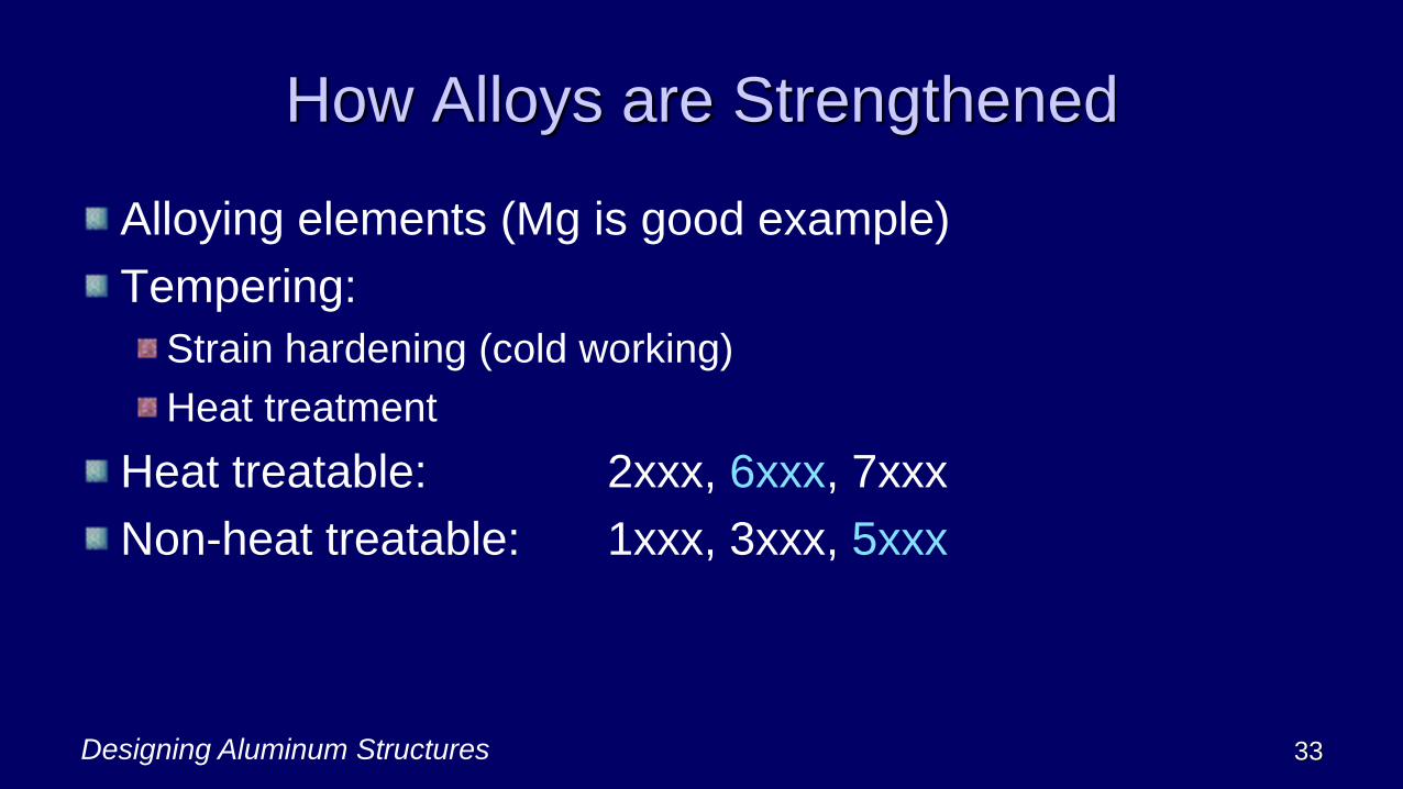
How Alloys are Strengthened
Alloying elements (Mg is good example)
Tempering:
Strain hardening (cold working)
Heat treatment
Heat treatable: 2xxx, 6xxx, 7xxx
Non-heat treatable: 1xxx, 3xxx, 5xxx
Designing Aluminum Structures 34
Annealed Condition
Before tempering, alloys start in the annealed condition (-
O suffix)
Annealed condition is weakest but most ductile
Tempering increases strength, but decreases ductility
Most alloys are annealed by heating to 650oF (melting
point is about 1100oF)

Designing Aluminum Structures 35
Strain Hardening
Mechanical deformation at ambient temps
For sheet and plate, deformation is by rolling to reduce
the thickness
Some non-heat treatable alloys undergo a stabilization
heat treatment
Purpose: to prevent age softening
Only used for some Al-Mg (5xxx) alloys
Designing Aluminum Structures 36
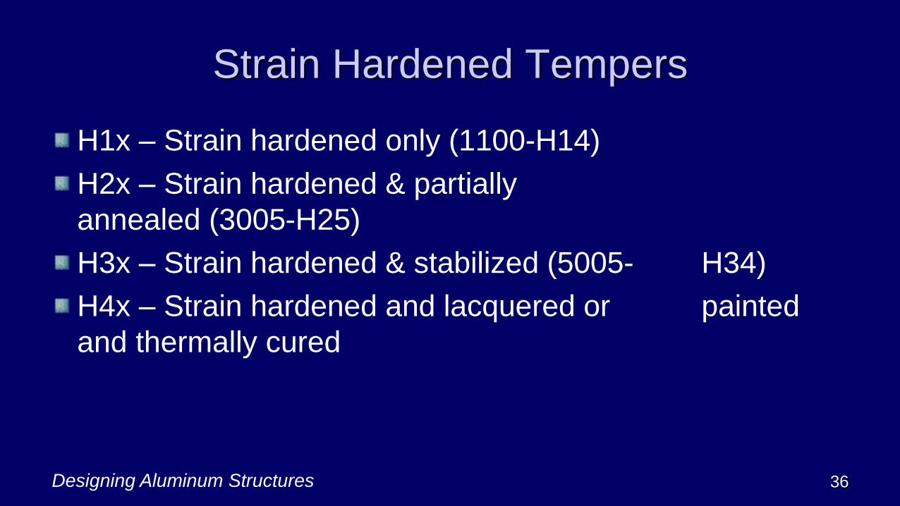
Strain Hardened Tempers
H1x – Strain hardened only (1100-H14)
H2x – Strain hardened & partially
annealed (3005-H25)
H3x – Strain hardened & stabilized (5005- H34)
H4x – Strain hardened and lacquered or painted
and thermally cured
Designing Aluminum Structures 37
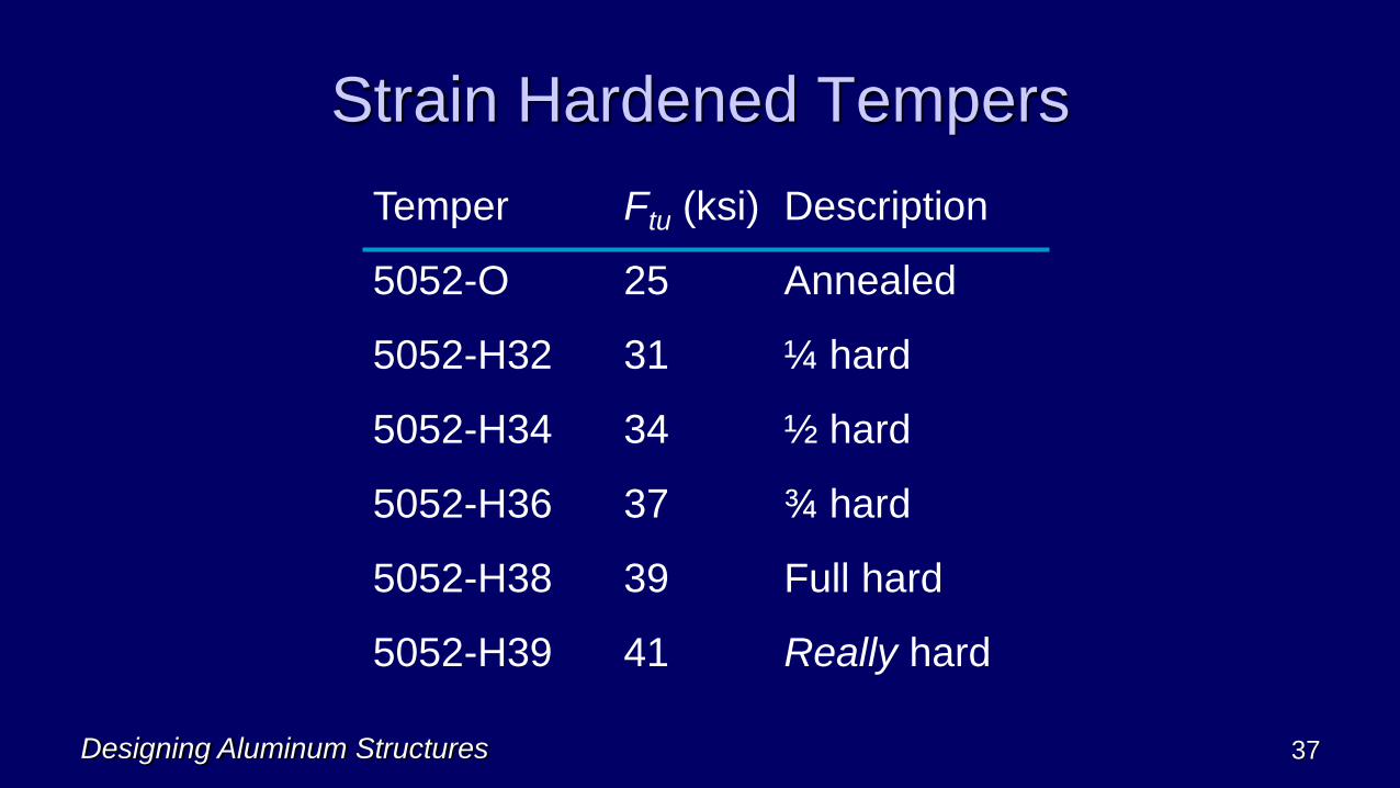
Strain Hardened Tempers
Temper Ftu (ksi) Description
5052-O 25 Annealed
5052-H32 31 ¼ hard
5052-H34 34 ½ hard
5052-H36 37 ¾ hard
5052-H38 39 Full hard
5052-H39 41 Really hard

Designing Aluminum Structures 38
Effect of Strain Hardening 5052
0
5
10
15
20
25
30
35
40
45
-O -H32 -H34 -H36 -H38 -H39
Ultimate Strength(ksi)
Yield Strength (ksi)
Elongation
Designing Aluminum Structures 39
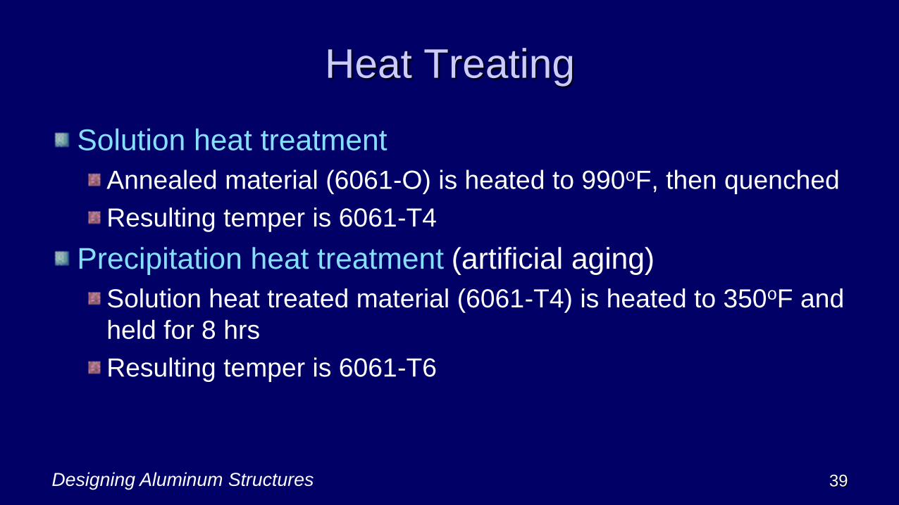
Heat Treating
Solution heat treatment
Annealed material (6061-O) is heated to 990oF, then quenched
Resulting temper is 6061-T4
Precipitation heat treatment (artificial aging)
Solution heat treated material (6061-T4) is heated to 350oF and
held for 8 hrs
Resulting temper is 6061-T6
Designing Aluminum Structures 40
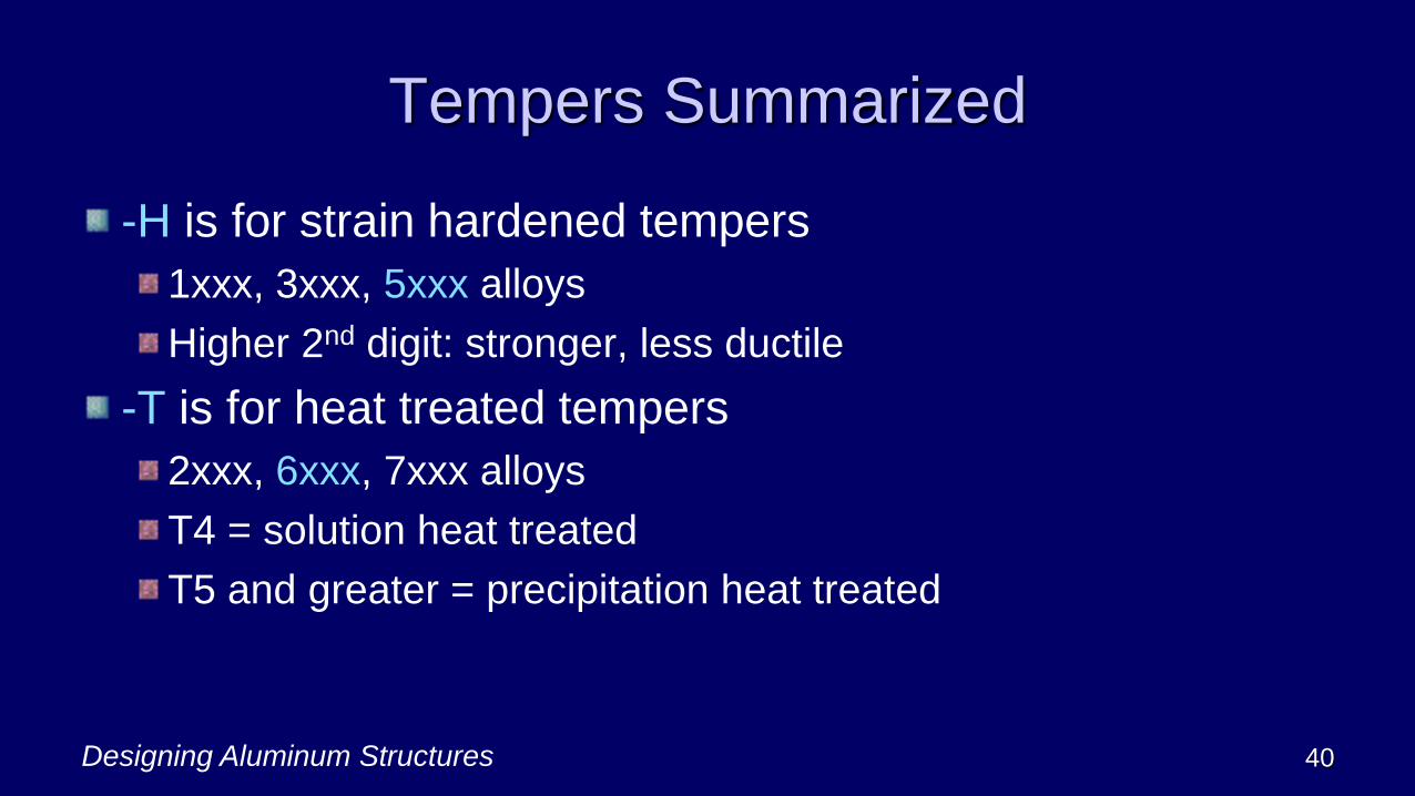
Tempers Summarized
-H is for strain hardened tempers
1xxx, 3xxx, 5xxx alloys
Higher 2nd digit: stronger, less ductile
-T is for heat treated tempers
2xxx, 6xxx, 7xxx alloys
T4 = solution heat treated
T5 and greater = precipitation heat treated
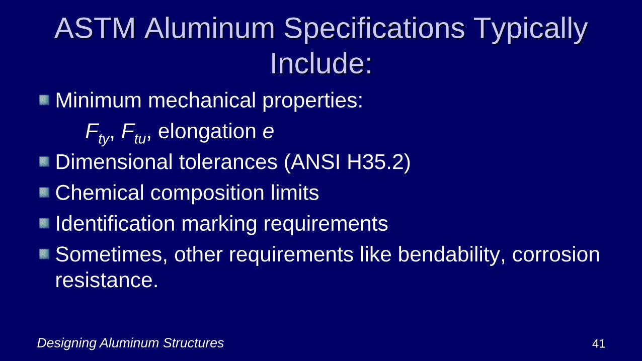
ASTM Aluminum Specifications Typically
Include:Minimum mechanical properties:
Fty, Ftu, elongation e
Dimensional tolerances (ANSI H35.2)
Chemical composition limits
Identification marking requirements
Sometimes, other requirements like bendability, corrosion
resistance.
Designing Aluminum Structures 41
Designing Aluminum Structures 42
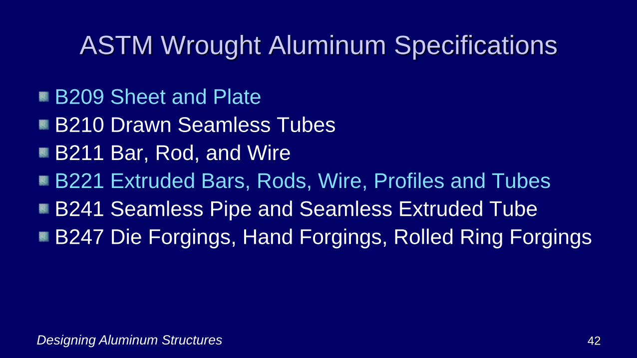
ASTM Wrought Aluminum Specifications
B209 Sheet and Plate
B210 Drawn Seamless Tubes
B211 Bar, Rod, and Wire
B221 Extruded Bars, Rods, Wire, Profiles and Tubes
B241 Seamless Pipe and Seamless Extruded Tube
B247 Die Forgings, Hand Forgings, Rolled Ring Forgings

Designing Aluminum Structures 43
ASTM Wrought Aluminum Specifications
B308 Standard Structural Profiles
B316 Rivet and Cold Heading Wire and Rod
B429 Extruded Structural Pipe and Tube
B632 Rolled Tread Plate
B928 High Magnesium Aluminum Alloy Sheet and Plate for Marine and Similar Service (has corrosion resistance reqs)
There are others not included in SAS
Designing Aluminum Structures 44
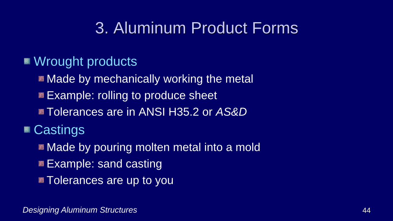
3. Aluminum Product Forms
Wrought products
Made by mechanically working the metal
Example: rolling to produce sheet
Tolerances are in ANSI H35.2 or AS&D
Castings
Made by pouring molten metal into a mold
Example: sand casting
Tolerances are up to you
Designing Aluminum Structures 45
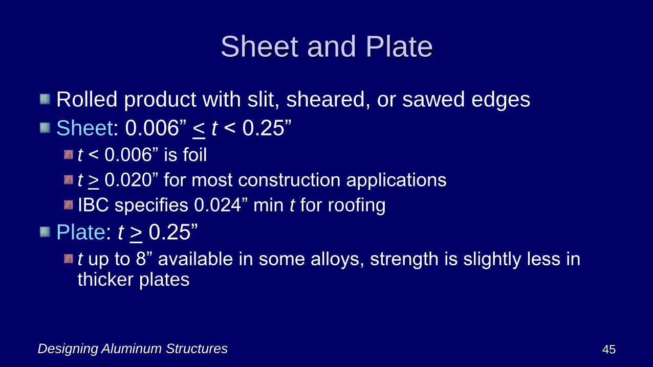
Sheet and Plate
Rolled product with slit, sheared, or sawed edges
Sheet: 0.006” < t < 0.25”
t < 0.006” is foil
t > 0.020” for most construction applications
IBC specifies 0.024” min t for roofing
Plate: t > 0.25”
t up to 8” available in some alloys, strength is slightly less in thicker plates

Designing Aluminum Structures 46
Extrusions
Made by pushing solid material through an opening called
a die
Offers great flexibility to designers
Solid and hollow shapes can be extruded
Some alloys are easier to extrude
Maximum circle size
for common products ≈ 19”
for special products ≈ 30”

Designing Aluminum Structures 47
Extruded Shapes

Designing Aluminum Structures 48
Aluminum Association Standard
I-beams and Channels
15 I-Beams 20 Channels

Designing Aluminum Structures 49
4. Aluminum Material Properties
Strengths
Modulus of Elasticity, Poisson’s Ratio
Ductility
Effect of Welding on Properties
Effect of Temperature on Properties
Physical Properties

Stress-Strain for Several Alloys
Designing Aluminum Structures 50
0
5
10
15
20
25
30
35
40
45
0.00 0.01 0.02 0.03 0.04 0.05 0.06 0.07 0.08 0.09 0.10
Str
ess
Strain
6061-T6 extr, n = 44.3
6061-T6 sheet, n = 21.2
6063-T5, n = 11.5
5052-H32, n = 12.6
5083-O, n = 5.5

Designing Aluminum Structures 51
Types of Strengths
Type of Stress Yield Ultimate
Tension Fty Ftu
Compression
H temper:
other tempers:
Fcy = 0.9Fty
Fcy = 1.0 Fty
−
Shear Fsy = 0.6Fty Fsu = 0.6Ftu

Designing Aluminum Structures 52
Some Aluminum Alloy Strengths
Alloy-temper, product Fty
ksi
Ftu
ksi
5052-H32 sheet & plate 23 31
5083-H116 plate
< 1.5” thick
31 44
6061-T6 extrusions 35 38
6063-T5 extrusions
< 0.5” thick
16 22
Designing Aluminum Structures 53
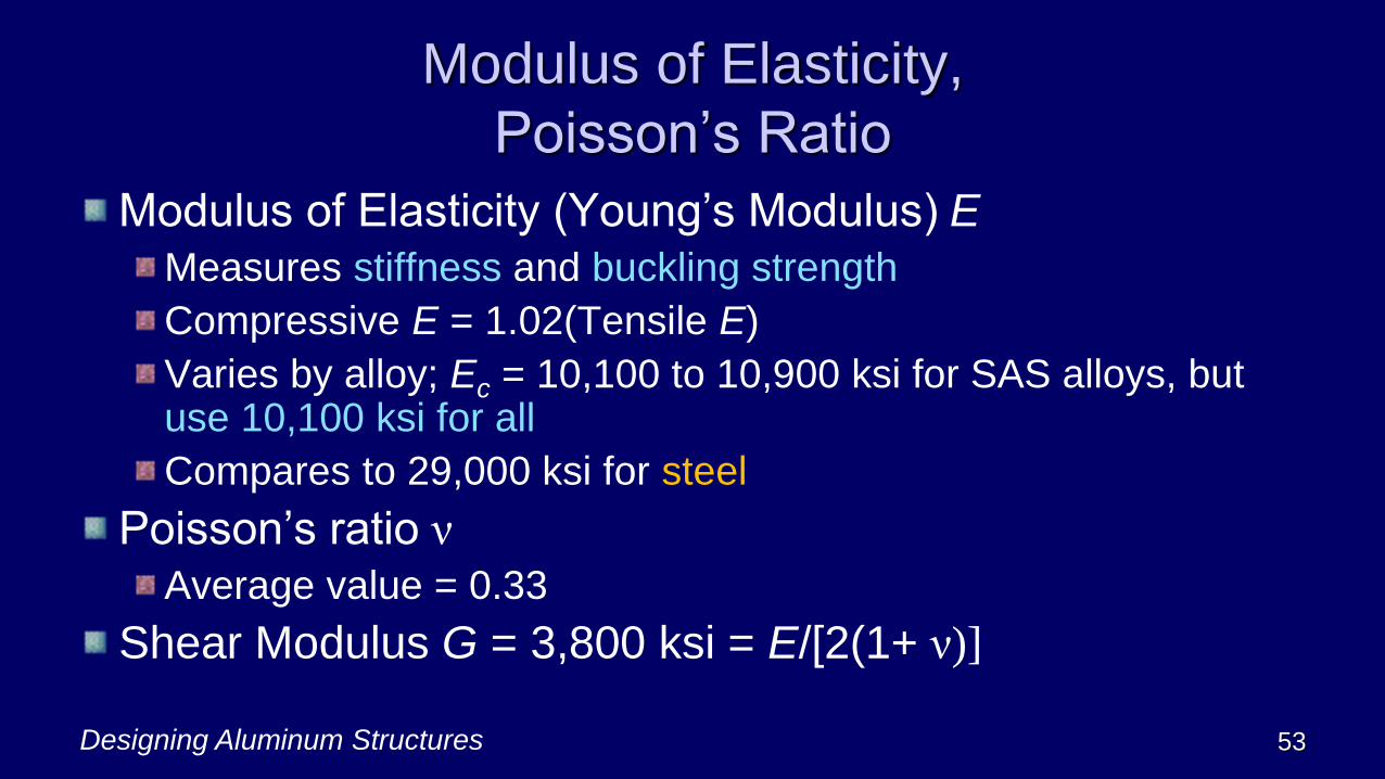
Modulus of Elasticity,
Poisson’s Ratio
Modulus of Elasticity (Young’s Modulus) E
Measures stiffness and buckling strength
Compressive E = 1.02(Tensile E)
Varies by alloy; Ec = 10,100 to 10,900 ksi for SAS alloys, but use 10,100 ksi for all
Compares to 29,000 ksi for steel
Poisson’s ratio ν
Average value = 0.33
Shear Modulus G = 3,800 ksi = E/[2(1+ ν)]

Designing Aluminum Structures 54
Ductility
Ductility: the ability of a material to withstand plastic strain
before rupture
Fracture Toughness: Aluminum doesn’t have a transition
temperature like steel
Elongation e
ASTM E292 Notch-Yield Ratio =
(Ftu of standard notched specimen)/Fty
If notch-yield ratio > 1, not brittle

Effect of Welding
Designing Aluminum Structures 55
Non-Heat Treatable Alloys Heat Treatable Alloys
before
welding
after
welding
cold
work
anneale
d
anneale
d
after
welding
anneale
d
before
welding
precipitation heat
treatment
solution heat
treatment
Str
ength
Designing Aluminum Structures 56
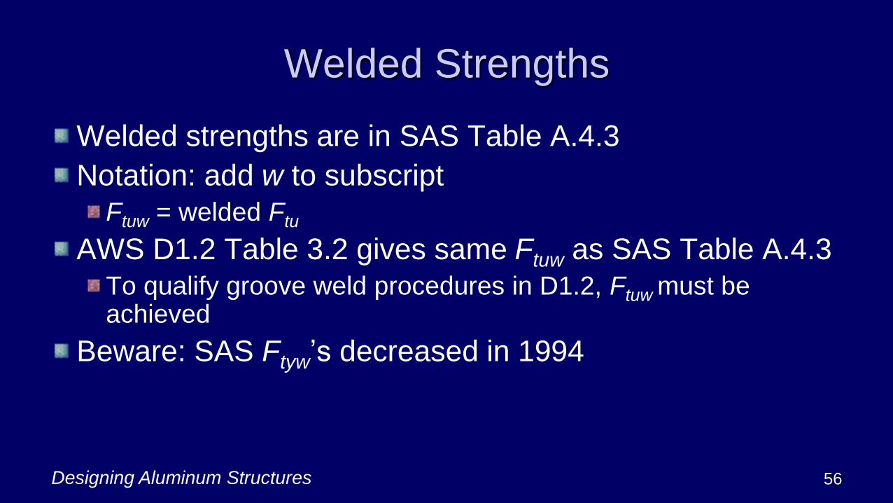
Welded Strengths
Welded strengths are in SAS Table A.4.3
Notation: add w to subscript
Ftuw = welded Ftu
AWS D1.2 Table 3.2 gives same Ftuw as SAS Table A.4.3
To qualify groove weld procedures in D1.2, Ftuw must be achieved
Beware: SAS Ftyw’s decreased in 1994
Designing Aluminum Structures 57
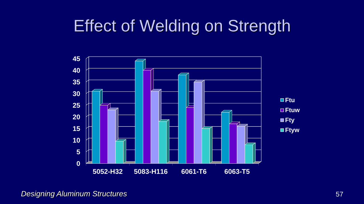
Effect of Welding on Strength
0
5
10
15
20
25
30
35
40
45
5052-H32 5083-H116 6061-T6 6063-T5
Ftu
Ftuw
Fty
Ftyw

Designing Aluminum Structures 58
Effect of Temperature
Below room temperature:
Elongation and strengths increase
Risk of brittle fracture does not increase
Above about 150oF:
Elongation increases
Strengths and modulus of elasticity decrease
Aluminum is pretty worthless (structurally) above about 450oF

Designing Aluminum Structures 59
Physical Properties
Density γ
Average value = 0.1 lb/in3
Varies by alloy; for alloys in ASD, +3%, -5%
Example: 6061-T6 density = 0.098 lb/in3
Coefficient of Thermal Expansion α
Average value = 13 x 10-6/oF
Varies slightly by alloy and temperature
Lengths over 30 ft: consider expansion joints
Designing Aluminum Structures 60
5. Structural Design Overview
Types of structures
Limit states
Strength limit state design methods:
Allowable Strength Design (ASD)
Load and Resistance Factor Design (LRFD)
Determining required forces

Designing Aluminum Structures 61
Types of Structures
Building-type structure: a structure of the type addressed
by a building code
Bridge-type structure: a structure not addressed by
building codes and designed for highway, pedestrian, or
rail traffic
Other structures: everything else (for example, lifting
equipment)
Required reliability depends on structure type

Designing Aluminum Structures 62
Limit States
A structural engineer considers limit states
Static strength
▪ available strength > required strength
Serviceability (deflection, vibration, etc.)
Fatigue
▪ allowable stress range > applied stress range

ENGINEER
What my friends think I do What my mother thinks I do What my wife thinks I do
What society thinks I do
What I think I do
What I really do
63Designing Aluminum Structures

Designing Aluminum Structures 64
What a Structural Engineer Does
Analysis: determine forces, moments in the structure
(required strength)
Use the same methods for all materials
But beware: since aluminum is more flexible than steel, 2nd
order effects may be more significant
Design: proportion the aluminum structure to safely resist
the loads (provide available strength)
Designing Aluminum Structures 65
ASD vs. LRFD
Allowable Strength Design (ASD):
(strength)/(safety factor) > load effect
allowable strength > load effect
Load & Resistance Factor Design (LRFD):
(strength)(resistance factor) > (load
factor)(load effect)
design strength > (load factor)(load effect)
In both, available strength > req’d strength
The difference is load factors

Designing Aluminum Structures 66
Aluminum ASD vs. LRFD
Since dead load is a small part of the load in most
aluminum structures, LRFD isn’t as significant for
aluminum:
If D = 0.05L, LRFD is 1.2D + 1.6L = 1.66L
w/ same load factors, 1.6D + 1.6L = 1.68L
Also, many aluminum structures are designed for a single
load (e.g., curtain walls are designed for wind only)

Designing Aluminum Structures 67
Safety/Resistance Factors for Aluminum
Building Structures
Limit State Safety
Factor Ω
Resistance
Factor
Yield Ωy = 1.65 y = 0.90
(was 0.95)
Rupture Ωu = 1.95 u = 0.75
(was 0.85)
Fastener
Rupture
Ωf = 2.34 f = 0.65
Designing Aluminum Structures 68
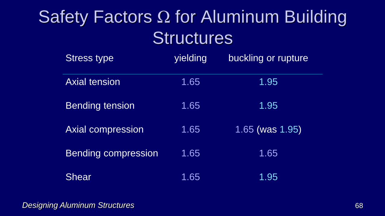
Safety Factors Ω for Aluminum Building
StructuresStress type yielding buckling or rupture
Axial tension 1.65 1.95
Bending tension 1.65 1.95
Axial compression 1.65 1.65 (was 1.95)
Bending compression 1.65 1.65
Shear 1.65 1.95

Designing Aluminum Structures 69
SAS Section C.2: Analysis
Must Account for:Axial, flexural, and shear deformations
Second-order effects (P-Δ and P-δ)
Geometric imperfections (use construction and fabrication
tolerances)
Effect of inelasticity on flexural stiffness (use τb I in place
of I )
Uncertainty in stiffness and strength (use 0.8E in place of
E, i.e. 8,000 ksi)

Designing Aluminum Structures 70
Thank You
Please contact me with questions
office: 919-493-8952; cell: 919-636-0072