introduction to autocad 2012 · introduction to autocad 2012 alf yarwood chapter 17 exercise 1 1....
TRANSCRIPT

Introduction to AutoCAD 2012Alf Yarwood
Chapter 17 Exercise 11. Open AutoCAD 2012 with a double-click on its shortcut icon in the Windows desktop.2. Open the template acadiso3D.dwt.3. Use the two layers 0 and Cyan.4. Set the variable UCSFOLLOW to 1.5. At the command line:
Command: enter ucs right-clickCurrent ucs name: *WORLD*Enter an option [New/Move/orthoGraphic/Prev/Restore/Save/Del/Apply/?/World]<World>: enter g (for orthoGraphic) right-clickEnter an option [Top/Bottom/Front/BAck/Left/Right]<Top>: enter f (for Front) right-clickRegenerating model.Command:
6. Zoom to 1.7. Construct a closed polyline outline for the bracket and extrude to a height of 60. Note the external radius of
the left-hand end of the bracket is 25.8. Place in the ViewCube/Isometric view. Then, at the command line:
Command: enter ucs right-clickCurrent ucs name: *FRONT*Enter an option [New/Move/orthoGraphic/Prev/Restore/Save/Del/Apply/?/World]<World>: enter n (for New) right-clickSpecify origin of new UCS or [ZAxis/3point/OBject/Face/View/X/Y/Z] <0,0,0>: enter f (for Face) right-clickSelect face of solid object: pick the upper sloping faceEnter an option [Next/Xflip/Yflip] <accept>: right-clickunless the wrong face is highlighted, enter n (for Next) andcontinue if needed until correct face is chosenRegenerating model.Command:
9. The drawing area regenerates with the upper face as the new UCS.10 Construct a cylinder for the hole into which the pin fits at 75 from the right-hand end of the face and subtract
it from the face. Note the height of the cylinder is -15 (because the upper surface of the face is lying in theUCS plane).
11. Make the layer Cyan current and construct two cylinders for the pin that fits into the upper arm of thebracket. Note the negative numbers given to the heights of the cylinders in the following command linesequence.
Command: _cylinderCurrent wire frame density: ISOLINES=4Specify center point for base of cylinder or [Elliptical] <0,0,0>: .xy of pick centre of hole(need Z): enter -15 right-clickSpecify radius for base of cylinder or [Diameter]: enter 20 right-clickSpecify height of cylinder or [Center of other end]: enter -10 right-clickCommand: right-clickCYLINDERCurrent wire frame density: ISOLINES=4
Material accompanying Introduction to AutoCAD 2012, ISBN 9780080969473. Copyright © 2011, Alf Yarwood.Published by Elsevier Ltd. All rights reserved.
Page 1

Specify center point for base of cylinder or [Elliptical]<0,0,0>: enter .xy right-clickof pick centre of hole (need Z): enter -15 right-clickSpecify radius for base of cylinder or [Diameter]: enter 15right-clickSpecify height of cylinder or [Center of other end]: enter30 right-clickCommand:
12. The two cylinders of the nut have now been constructed. Join the twocylinders to form a union.
Command: _unionSelect objects: pick one of the cylinders 1 foundSelect objects: pick the other 1 found, 2 totalSelect objects: right-clickCommand:
13. Place the window in the UCS FRONT view to check the pin is correctand Zoom to 1.
14. Make the layer 0 current.15. Place the drawing in the ViewCube/Isometric view, enter ucs at the
command line and pick the bottom face. Construct the cylinder for thehole and subtract it from the bracket.
16. Make layer Cyan current and construct another nut in its position in thehole.
17. Place the drawing in the UCS WORLD.18. Add suitable lighting and materials to the pins and bracket.19. Place the drawing in the ViewCube/Isometric view and render.20. Save the drawing with a file name 17_Exercise01.dwg to a memory
stick.
Chapter 17 Exercise 21. Open AutoCAD 2012 with a double-click on its shortcut icon in the Windows desktop.2. Open the template acadiso3D.dwt.3. Construct two concentric polygons each of six sides, the first of an edge length 46 and the second of an edge
length 80.4. Extrude the first polygon to a height of 60 and the second to a height of 30.5. Set UCSFOLLOW to 1.6. Place the drawing in the Front view, move the smaller extrusion to sit on top of the larger and form a union
of the two solids.7. Place the union in the ViewCube/Isometric view and enter ucs at the command line.
Command: enter ucs right-clickCurrent ucs name: *FRONT*Enter an option [New/Move/orthoGraphic/Prev/Restore/Save/Del/Apply/?/World]<World>: enter n (New) right-clickSpecify origin of new UCS or [ZAxis/3point/OBject/Face/View/X/Y/Z] <0,0,0>: enter f (Face) right-clickSelect face of solid object: pick a face of the lowerextrusionEnter an option [Next/Xflip/Yflip] <accept>: right-clickRegenerating model.Command:
Material accompanying Introduction to AutoCAD 2012, ISBN 9780080969473. Copyright © 2011, Alf Yarwood.Published by Elsevier Ltd. All rights reserved.
Page 2
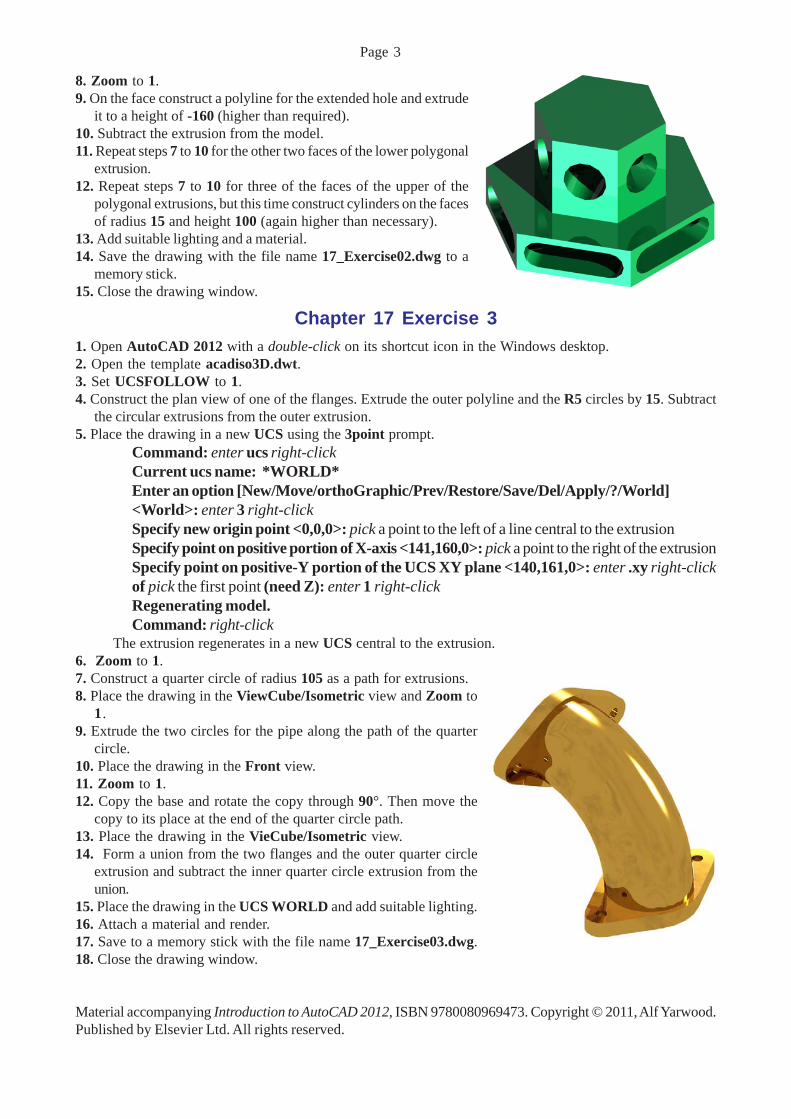
8. Zoom to 1.9. On the face construct a polyline for the extended hole and extrude
it to a height of -160 (higher than required).10. Subtract the extrusion from the model.11. Repeat steps 7 to 10 for the other two faces of the lower polygonal
extrusion.12. Repeat steps 7 to 10 for three of the faces of the upper of the
polygonal extrusions, but this time construct cylinders on the facesof radius 15 and height 100 (again higher than necessary).
13. Add suitable lighting and a material.14. Save the drawing with the file name 17_Exercise02.dwg to a
memory stick.15. Close the drawing window.
Chapter 17 Exercise 31. Open AutoCAD 2012 with a double-click on its shortcut icon in the Windows desktop.2. Open the template acadiso3D.dwt.3. Set UCSFOLLOW to 1.4. Construct the plan view of one of the flanges. Extrude the outer polyline and the R5 circles by 15. Subtract
the circular extrusions from the outer extrusion.5. Place the drawing in a new UCS using the 3point prompt.
Command: enter ucs right-clickCurrent ucs name: *WORLD*Enter an option [New/Move/orthoGraphic/Prev/Restore/Save/Del/Apply/?/World]<World>: enter 3 right-clickSpecify new origin point <0,0,0>: pick a point to the left of a line central to the extrusionSpecify point on positive portion of X-axis <141,160,0>: pick a point to the right of the extrusionSpecify point on positive-Y portion of the UCS XY plane <140,161,0>: enter .xy right-clickof pick the first point (need Z): enter 1 right-clickRegenerating model.Command: right-click
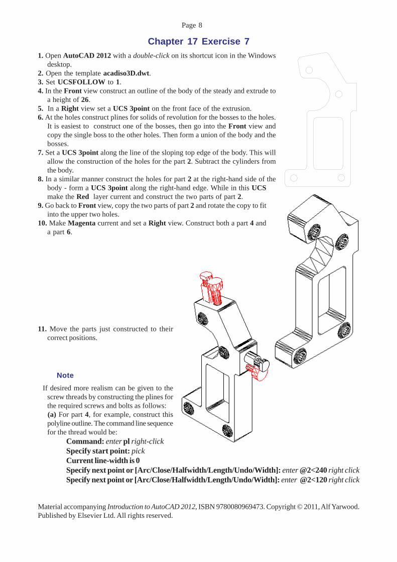
The extrusion regenerates in a new UCS central to the extrusion.6. Zoom to 1.7. Construct a quarter circle of radius 105 as a path for extrusions.8. Place the drawing in the ViewCube/Isometric view and Zoom to
1.9. Extrude the two circles for the pipe along the path of the quarter
circle.10. Place the drawing in the Front view.11. Zoom to 1.12. Copy the base and rotate the copy through 90°. Then move the
copy to its place at the end of the quarter circle path.13. Place the drawing in the VieCube/Isometric view.14. Form a union from the two flanges and the outer quarter circle
extrusion and subtract the inner quarter circle extrusion from theunion.
15. Place the drawing in the UCS WORLD and add suitable lighting.16. Attach a material and render.17. Save to a memory stick with the file name 17_Exercise03.dwg.18. Close the drawing window.
Material accompanying Introduction to AutoCAD 2012, ISBN 9780080969473. Copyright © 2011, Alf Yarwood.Published by Elsevier Ltd. All rights reserved.
Page 3

Chapter 17 Exercise 41. Open AutoCAD 2012 with a double-click on its shortcut icon in the Windows desktop.2. Open the template acadiso3D.dwt.3. Reset Limits to an A3 size (594 x 420) as follows:
Command: enter limits right-clickReset Model space limits:Specify lower left corner or [ON/OFF] <0,0>: right-clickSpecify upper right corner <420,297>: enter 594,420 right-clickCommand: enter z right-clickSpecify corner of window, enter a scale factor (nX or nXP), or[All/Center/Dynamic/Extents/Previous/Scale/Window/Object] <real time>: enter a right-clickCommand:
4. Set UCSFOLLOW to 1.5. Set the UCS to FRONT and Zoom to 1.6. On layer 0 construct the outline of the front view of the left-hand end of part of the arm and extrude to a
height of 20. Subtract the hole from the arm.
7. Set the screen to the Top view and Zoom to 1.8. Construct a polyline outline of the plan of the right-hand end of the arm and extrude to a height of 15.9. Set the Front view, Zoom to 1 and move the right-hand end of the arm to its position at the end of the left-
hand end. Form a union of the two parts.10. Place in the ViewCube/Isometric view. Fillet the left-hand edges to a radius of 10 and the curves of the
handle to a radius of 5 (using the Chain prompt of the Fillet command line sequence).
Material accompanying Introduction to AutoCAD 2012, ISBN 9780080969473. Copyright © 2011, Alf Yarwood.Published by Elsevier Ltd. All rights reserved.
Page 4

12. Make Red current.13. In the Front view construct a polyline outline for a solid of revolution for the spindle.14. Set ISOLINES to 12.15. Form a solid of revolution for the spindle using the Revolve tool from the 3Home/3D Modeling panel.16. Make layer 0 current and construct a cylinder for the hole in the arm to take the pin.17. In the Front view move the hole and spindle to their correct positions in the arm and subtract the hole from
the arm.
18. Make Magenta current, construct a plineoutline for a solid of revolution of the pin andrevolve.
19. Make Magenta current and constructoutlines for the base. Extrude the curbed partto a height of 20 and the rectangular base toa height of 90.
20. In the Top view move the parts to their correctpositions relative to each other. Constructcylinders for the holes in the base.
21. Go back to the Front view and move theholes to their correct places in the base. Unionthe two parts of the base and subtract theholes.
22. Place the drawing in the ViewCube/Isometricview and fillet the corners of the base plate to aradius of 20.
23. Go back to the Top view and add lights - aPoint light above, a Distant light to the frontand above, and another Distant light to the left-front and above.
Material accompanying Introduction to AutoCAD 2012, ISBN 9780080969473. Copyright © 2011, Alf Yarwood.Published by Elsevier Ltd. All rights reserved.
Page 5

24. Place in the ViewCube/Isometric view and attach materials to the parts of the model.25. Save the drawing in a memory stick with the file name 17_Exercise04.dwg.26. Close the drawing window.
Chapter 17 Exercise 51. Open AutoCAD 2012 with a double-click on its shortcut icon in
the Windows desktop.2. Open the template acadiso3D.dwt.3. Construct a polyline outline for the base of the device, extrude all
parts to a height of 7.5 and subtract the holes from the base.4. Set UCSFOLLOW to 1.5. At the command line:
Command: enter ucs right-clickCurrent ucs name: *WORLD*Enter an option [New/Move/orthoGraphic/Prev/Restore/Save/Del/Apply/?/World]<World>: enter 3 right-clickSpecify new origin point <0,0,0>: pick a point to the left and central to the planSpecify point on positive portion of X-axis<116,170,0>: pick a point to the right and central to theplanSpecify point on positive-Y portion of the UCS XYplane <115,171,0>: enter .xy right-clickof pick the first point (need Z): enter 1 right-clickRegenerating model.Command:
6. Zoom to 1.7. Set ISOLINES to 12.
8. On this new UCS plane which is central to the base construct apolyline for a solid of revolution for the upright part of the deviceand revolve the pline through 360°.
9. Place the drawing in the ViewCube/Isometric view and Zoomto 1.
10. Union the two parts and fillet the join to a radius of 5.
11. Add lighting to the model and attach a material.12. Render the model.13. Save the drawing with the file name 17_Exercise05.dwg to a
floppy disk.14. Close the drawing window.
Material accompanying Introduction to AutoCAD 2012, ISBN 9780080969473. Copyright © 2011, Alf Yarwood.Published by Elsevier Ltd. All rights reserved.
Page 6

Chapter 17 Exercise 61. Open AutoCAD 2012 with a double-click on its shortcut icon in the Windows desktop.2. Open the template acadiso3D.dwt.3. Set UCSFOLLOW to 1.
4. Place the AutoCAD drawing area in the Front view and construct an outline of the forkpart of the connector and extrude to a height of 40.
5. Place in the Top view and construct two cylinders, one of radius 15 and height50 and the other of radius 10 and height 60.
6. In the Front view move the two cylinders to their correct positions at the top ofthe fork.
7. Form a union between the fork and the larger cylinder and subtract the smallerfrom the union.
8. In the Right view construct a cylinder of radius 10 and height 70 for the holesin the fork.
9. In the Front view move the cylinder to its correct position in the fork and subtractfrom the fork.
10 In the ViewCube/Isometric view fillet the bottom corners of the fork ends toa radius of 20.
11. Make the Cyan layer current.
12. In the Right view construct a cylinder for the pinof Radius 10 and height 100.
13. In the Front view move the cylinder into its correctposition central to the fork.
14. In the Top view add suitable lighting.15. In the ViewCube/Isometric view attach
materials to the fork and pin and render the model.16. Call the 3D Orbit tool and move the model to a
new pictorial position.17. Save the model drawing with the file name
17_Exercise06.dwg to a memory stick.18. Close the drawing window.
Material accompanying Introduction to AutoCAD 2012, ISBN 9780080969473. Copyright © 2011, Alf Yarwood.Published by Elsevier Ltd. All rights reserved.
Page 7
Chapter 17 Exercise 71. Open AutoCAD 2012 with a double-click on its shortcut icon in the Windows
desktop.2. Open the template acadiso3D.dwt.3. Set UCSFOLLOW to 1.4. In the Front view construct an outline of the body of the steady and extrude to
a height of 26.5. In a Right view set a UCS 3point on the front face of the extrusion.6. At the holes construct plines for solids of revolution for the bosses to the holes.
It is easiest to construct one of the bosses, then go into the Front view andcopy the single boss to the other holes. Then form a union of the body and thebosses.
7. Set a UCS 3point along the line of the sloping top edge of the body. This willallow the construction of the holes for the part 2. Subtract the cylinders fromthe body.
8. In a similar manner construct the holes for part 2 at the right-hand side of thebody - form a UCS 3point along the right-hand edge. While in this UCSmake the Red layer current and construct the two parts of part 2.
9. Go back to Front view, copy the two parts of part 2 and rotate the copy to fitinto the upper two holes.
10. Make Magenta current and set a Right view. Construct both a part 4 anda part 6.
11. Move the parts just constructed to theircorrect positions.
Note If desired more realism can be given to the
screw threads by constructing the plines forthe required screws and bolts as follows:
(a) For part 4, for example, construct thispolyline outline. The command line sequencefor the thread would be:
Command: enter pl right-clickSpecify start point: pickCurrent line-width is 0Specify next point or [Arc/Close/Halfwidth/Length/Undo/Width]: enter @2<240 right clickSpecify next point or [Arc/Close/Halfwidth/Length/Undo/Width]: enter @2<120 right click
Material accompanying Introduction to AutoCAD 2012, ISBN 9780080969473. Copyright © 2011, Alf Yarwood.Published by Elsevier Ltd. All rights reserved.
Page 8

Specify next point or [Arc/Close/Halfwidth/Length/Undo/Width]: enter @2<240 right- clickSpecify next point or [Arc/Close/Halfwidth/Length/Undo/Width]: enter @2>120 right- click
and so on until the required length of thread is completed.(b) Then call REVOLVE. The result will be as shown.(c) The screwed holes for the screws and bolts could be
constructed in a similar manner.
12. Add suitable lighting and materials and render the completedmodel.
13. Save the model drawing with the file name17_Exercise07.dwg in a memory stick.
14. Close the drawing window.
Material accompanying Introduction to AutoCAD 2012, ISBN 9780080969473. Copyright © 2011, Alf Yarwood.Published by Elsevier Ltd. All rights reserved.
Page 9

Page 10
Exercise 81. Open AutoCAD 2012 with a double-click on its shortcut icon in the Windows desktop.2. Open the template acadiso3D.dwt.3. Construct plines as shown - working to your own
dimensions.4. Place the drawing in the Front view, Zoom to 1 and
copy the plines vertically upwards by a suitable numberof units.
5. Place in the Southwest Isometric view.6. Set SURFTAB1 to 36 and SURFTAB2 to 2.7. Enter rulesurf at the command line. The command line shows:
Command: _rulesurfCurrent wire frame density:SURFTAB1=36Select first defining curve: pick the topline at the frontSelect second defining curve: pick thebottom line at the front.Command:
8. Continue forming the ruled surfaces on the other threesides and the base.
9. Make the layer Construction current.10. In the Front view make a new 3point UCS above
the top of the model.11. Construct pline arcs at the left and right-hand ends
the same as those in the model and plines from theends of the arcs.
12. Turn layer 0 off.13. Form a 3point UCS across the ends of the smaller
arc and construct a pline arc between the ends of thesmaller arc.
14. Go back to the Front view and form an arc in asimilar manner across the ends of the larger arc.
15. Form edgesurfs across each of the three surfaces.16. Open layer 0 and make it the current layer.17. Call Hide
Material accompanying Introduction to AutoCAD 2012, ISBN 9780080969473. Copyright © 2011, Alf Yarwood.Published by Elsevier Ltd. All rights reserved.

Page 11
18. Place in the Top view and add lighting.19. Attach materials and render.20. Save with the file name 18_Exercise01.dwg to a
memory stick.21. Close the drawing window.
Exercise 91. Open AutoCAD 2012 with a double-click on its shortcut icon in the Windows desktop.2. Open the template acadiso3D.dwt.
3. In the Front view construct the polyline asshown in Fig. ????.
4. In the Top view copy and rotate and move thepline until there are four plines as required forthe edgesurf surface.
5. Place the drawing in the Southwest Isometricview.
6. Set both SURFTAB1 and SURFTAB2 to 32.7. Enter edgesurf at the command line. Following the prompts at the command line pick each of the four plines
in turn
Material accompanying Introduction to AutoCAD 2012, ISBN 9780080969473. Copyright © 2011, Alf Yarwood.Published by Elsevier Ltd. All rights reserved.
Page 12
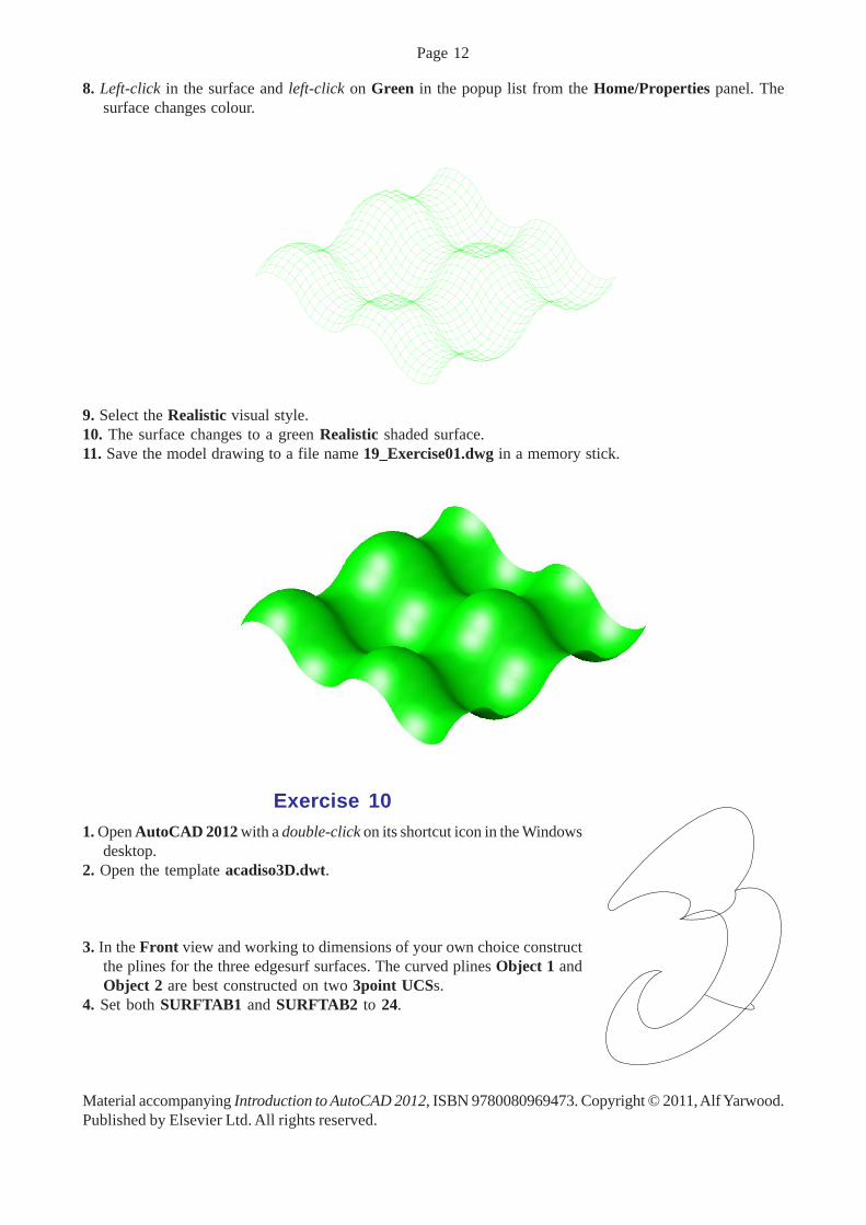
8. Left-click in the surface and left-click on Green in the popup list from the Home/Properties panel. Thesurface changes colour.
9. Select the Realistic visual style.10. The surface changes to a green Realistic shaded surface.11. Save the model drawing to a file name 19_Exercise01.dwg in a memory stick.
Exercise 101. Open AutoCAD 2012 with a double-click on its shortcut icon in the Windows
desktop.2. Open the template acadiso3D.dwt.
3. In the Front view and working to dimensions of your own choice constructthe plines for the three edgesurf surfaces. The curved plines Object 1 andObject 2 are best constructed on two 3point UCSs.
4. Set both SURFTAB1 and SURFTAB2 to 24.
Material accompanying Introduction to AutoCAD 2012, ISBN 9780080969473. Copyright © 2011, Alf Yarwood.Published by Elsevier Ltd. All rights reserved.

Page 13
5. Enter edgesurf at the command line and form thesurfaces by picking each of the four edges foreach of the three surfaces in turn.
6. Change the colour of the three surfaces to red.7. Erase the original plines on which the edgesurf
surfaces had been constructed.8. Set to the Shaded visual style.9. In the Top view add suitable lighting.
10. In the Southwest Isometric view attach a material and render.
11. Save the drawing to the file name 19_Exercise05.dwg in a memorystick.
12. Close the drawing window.12. Close the drawing window.
Exercise 111. Open AutoCAD 2012 with a double-click on its shortcut icon in the
Windows desktop.2. Open the template acadiso3D.dwt.3. Make a new layer magenta of colour magenta.
4. In the Top view construct a semicircle of radius 25.5. In the Front view construct a semicircle of radius 75. Move the semicircle
so that its left-hand end is central to the radius 25 circle.
6. Place in the Southeast Isometric view.7. Call the Extrude tool from the Home panel.8. Extrude the radius 25 semicircle along the path of the radius 75
semicircle.9. Save the model drawing with the file name 17_Exercise08.dwg in
a memory stick.10. Close the drawing window.
Material accompanying Introduction to AutoCAD 2012, ISBN 9780080969473. Copyright © 2011, Alf Yarwood.Published by Elsevier Ltd. All rights reserved.

Page 14
Additional exercises1. A rendering of a 3D solid model drawing of a small platform which can rotate in its forked holder is shown.
Construct a 3D solid model drawing of the platform and its holder working to the details given in the two-viewthird angle orthographic projection below. Add suitable lighting and materials and render the model.
2. A 3D solid model drawing of a garage is shown to theright and details of its sizes are given in a two-viewdrawing on below. The thickness of all parts except theroof is 2.5, the roof thickness being 2. The hatching ofthe roof and front wall needs to be placed on a flatplane which is then placed over the extrusions formingthe roof and wall. Construct the 3D solid model drawing.
Material accompanying Introduction to AutoCAD 2012, ISBN 9780080969473. Copyright © 2011, Alf Yarwood.Published by Elsevier Ltd. All rights reserved.
Page 15
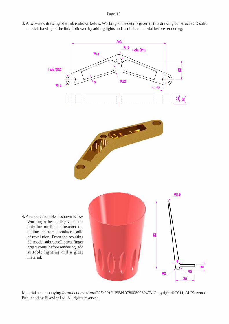
3. A two-view drawing of a link is shown below. Working to the details given in this drawing construct a 3D solidmodel drawing of the link, followed by adding lights and a suitable material before rendering.
4. A rendered tumbler is shown below.Working to the details given in thepolyline outline, construct theoutline and from it produce a solidof revolution. From the resulting3D model subtract elliptical fingergrip cutouts, before rendering, addsuitable lighting and a glassmaterial.
Material accompanying Introduction to AutoCAD 2012, ISBN 9780080969473. Copyright © 2011, Alf Yarwood.Published by Elsevier Ltd. All rights reserved

Page 16
Multiple choice questions1. The term UCS stands for:
(a) User Coordinate State(b) Using Coordinates Screen(c) User Coordinate System(d) User Coordinate Set
2. Before the UCS system can be used:(a) The set variable UCSFOLLOW must be set to 1(b) The set variable UCSFOLLOW must be set to 0(c) It does not matter whether the set variable UCSFOLLOW is set to any number, the UCS system willstill operate(d) The set variable UCSFOLLOW does not need to be set because it becomes operative when the UCSis in use
3. Before the UCS system can be used, the UCS icon:(a) Must be showing somewhere on screen(b) Need not appear anywhere on screen(c) Must be showing at the bottom left-hand corner of the screen(d) The UCS icon can only show on screen if the setting of the set variable UCSFOLLOW is correct
4. The term UCS WORLD applies to:(a) The plane on which the operator is working at the time(b) The standard XY plane which appears when AutoCAD is loaded on screen(c) Any one of the orthogonal planes(d) Any plane set when working in the UCS
5. A 2D outline constructed using the line and circle tools can be extruded to form a 3D model:(a) Yes(b) No(c) Only if it is first made into a region(d) Either if it is first made into a region or if its outline is edited to form a closed polyline
Material accompanying Introduction to AutoCAD 2012, ISBN 9780080969473. Copyright © 2011, Alf Yarwood.Published by Elsevier Ltd. All rights reserved.