introduction to buoyancy and “wet weight” 2 finding center ... · buoyant-the object neither...
TRANSCRIPT

Inside This Issue
1 Introduction to buoyancy and “wet weight”
2 Finding Center of Gravity in SolidWorks with the Tools command
3 SolidWorks “tips and tricks” to find Center of Buoyancy
4 Calculating “wet weight”
5 Does my object sink or float?

Introduction to buoyancy and “wet weight” When designing products for customers each project usually comes with its own unique set of
design requirements. These requirements are typically outlined in the product specification or
statement of work. Typical requirements for products include: Overall form factor, weight,
center of gravity, material selection, color, etc. However, when designing products that are to
be submerged in water a whole new sub-set of requirements and concerns need to be
considered and addressed. Some of these issues include: O-ring sealing, pressure vessel
penetrations, pressure vessel design and analysis, dissimilar metals, galvanic corrosion,
displaced volume, wet weight, and center of buoyancy. In this issue we will explore:
Buoyancy, Displaced Volume, Center of Buoyancy, Center of Gravity, and Wet Weight. We will
use SolidWorks to find center of gravity, displaced volume, and center of buoyancy. From
these findings one will be able to determine if the product sinks or floats!
Buoyancy Merriam-Webster’s definitions for buoyancy:
(a) The tendency of a body to float or to rise when submerged in a fluid
(b) The power of a fluid to exert an upward force on a body placed in it
Simply stated if an object displaces more fluid (usually water) than the object weighs it
will float if it does not it will sink (reference Figure 1)
Figure 1
Buoyancy = ρ fluid X Volume Displaced
Weight Object = Mass Object X Gravity
(+) Direction
(-) Direction

Displaced Volume Displaced Volume is the volume of water your object will “push out of its way” when you
submerge your object under water. For an individual item, such as a metal sphere, this is
easy to calculate or find using SolidWorks. Using SolidWorks>Tools>Mass Properties one
can measure the Volume (reference Figure 2). This volume is equal to your displaced
volume. However, when designing something that is made of multiple components,
varying wall thickness, air cavities, etc. the displaced volume cannot be found using this
method. A proven method using SolidWorks will be explored later in this issue.
Figure 2
Center of Buoyancy The center of buoyancy (CB) is the center of volume of displaced water, of an object,
and is the location where the buoyant force acts exerting a force that tries to lift the
object up in the water column. This force acts in the “+” direction (reference Figure 1)
Center of Gravity The center of gravity (CG) is the center of mass of an object and is the location where
the Weight force would be applied in a free body diagram. The Weight is the force that
tries to pull your object down in the water column. This force acts in the “-” direction
(reference Figure 1)

Wet Weight “Wet weight” sounds like a fictional term-however it is real term and is simple to calculate
and understand. Simply put, “wet weight” is how much your object would weigh if you
were to measure your object fully submerged. To calculate the wet weight of an object
all one needs to do is subtract the weight of the object from the buoyancy of the object.
Keep in mind these terms are force vectors and their respective signs “+” or “-“indicates
direction. Direction indicates if the object sinks or floats: “+” the object will float, “-“the
object will sink (reference Figure 1). If the term is “0” the item is said to be neutrally
buoyant-the object neither sinks nor floats but maintains elevation in the water column
until an outside force acts upon it.
Finding Center of Gravity in SolidWorks with the Tools command To find the Center of Gravity and the Weight of one’s part or assembly in SolidWorks open
Tools>Mass Properties. From here, a dialog box will appear listing the Output Coordinate
System, Mass, Volume, Surface Area, Center of Mass, and Moments of Inertia. Make sure that
all your separate part files, in your assembly, have accurate weight properties (e.g. Aluminum
Alloy 6061-T6, Stainless Steel 316L, etc.) otherwise Mass properties data will be inaccurate and
misleading!
Figure 3
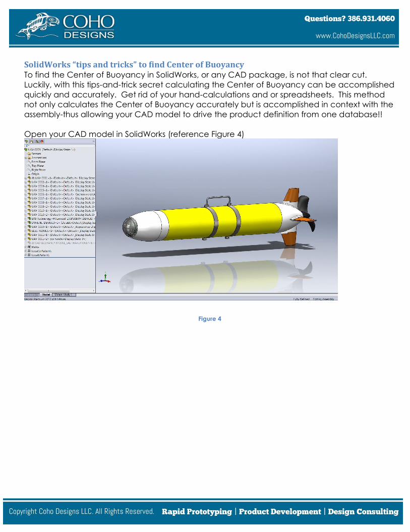
SolidWorks “tips and tricks” to find Center of Buoyancy To find the Center of Buoyancy in SolidWorks, or any CAD package, is not that clear cut.
Luckily, with this tips-and-trick secret calculating the Center of Buoyancy can be accomplished
quickly and accurately. Get rid of your hand-calculations and or spreadsheets. This method
not only calculates the Center of Buoyancy accurately but is accomplished in context with the
assembly-thus allowing your CAD model to drive the product definition from one database!!
Open your CAD model in SolidWorks (reference Figure 4)
Figure 4

Left Click the Configuration Manager tab, located in the feature tree right click the
assembly>Add configuration. Add a new configuration titled “Buoyancy Model” (reference
Figure 5)
Configuration Manager should have two configurations. The first configuration will be the
Default configuration. “Default configuration” is a Solid Works Default name and may be
different depending on your companies SolidWorks installation. The second configuration
should read: Buoyancy Model (reference Figure 6).
Figure 6
Figure 5

Activate the Default configuration by Double right click on the Default tab configuration
(reference Figure 7).
Figure 7
Left click on the Feature Manager Design Tree tab to return to the feature tree (reference
Figure 8).
Figure 8
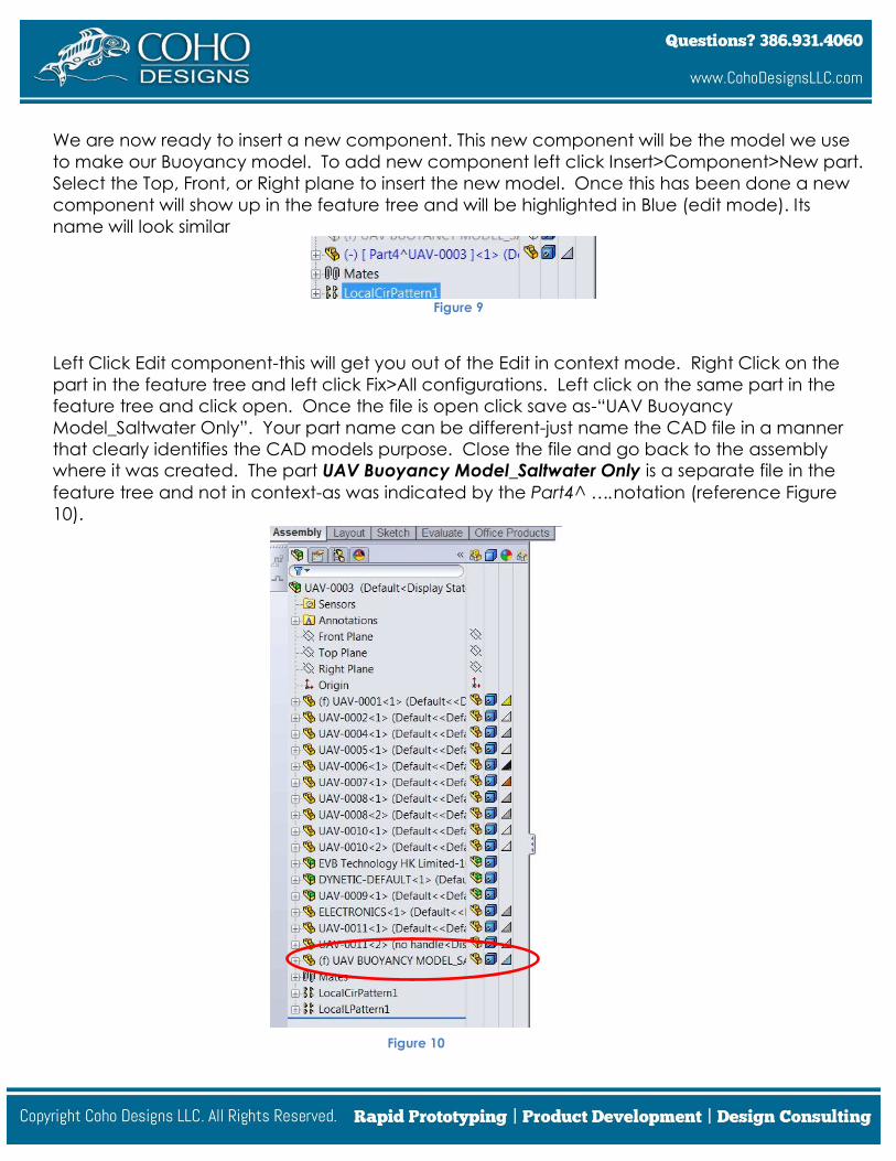
We are now ready to insert a new component. This new component will be the model we use
to make our Buoyancy model. To add new component left click Insert>Component>New part.
Select the Top, Front, or Right plane to insert the new model. Once this has been done a new
component will show up in the feature tree and will be highlighted in Blue (edit mode). Its
name will look similar
Figure 9
Left Click Edit component-this will get you out of the Edit in context mode. Right Click on the
part in the feature tree and left click Fix>All configurations. Left click on the same part in the
feature tree and click open. Once the file is open click save as-“UAV Buoyancy
Model_Saltwater Only”. Your part name can be different-just name the CAD file in a manner
that clearly identifies the CAD models purpose. Close the file and go back to the assembly
where it was created. The part UAV Buoyancy Model_Saltwater Only is a separate file in the
feature tree and not in context-as was indicated by the Part4^ ….notation (reference Figure
10).
Figure 10

Highlight UAV Buoyancy Model_Saltwater Only in the feature tree and left click Edit
Component. We are now in edit mode and are ready to create the buoyancy model. We will
use surfacing tools to accomplish this task. Look at your product and try to imagine every face
that is in contact with water. Another way to look at this-imagine adding heat shrink around
your product and everywhere there is heat shrink it will be in contact with water. If a face is not
in contact with water do not select it!!!
To accomplish this in SolidWorks, left click Insert>Surface>Offset. In the Offset command type
0.00 inches-we do not want to offset our surface, in or out, as this will affect our displaced
volume. Offset surface command will turn into Copy Surface command (reference Figure 11).
To add faces to the Offset Parameters box start left clicking on faces that are in contact with
water (reference Figure 12).
Figure 11
Figure 12

Once all the faces have been selected exit the Edit mode and open the UAV Buoyancy
Model_Saltwater Only file. Once open, SolidWorks surfacing tools will need to be used to
extend, trim, and knit surfaces such that one can define a surface that is “water tight”
(reference Figure 13).
Figure 13
You may have multiple bodies in the feature tree. If so, CNTRL select Solid Bodies in the Solid
Bodies Folder in the feature tree>right click>Combine. Select the radio button>Add (reference
Figure 14).
Figure 14

Now we have a 3D model with one Solid body in the feature tree. However, it does not have
the correct material specified to make it our buoyancy model. To do this we need to add a
material property to the model (reference Figure 15). Right Click Material>Edit Material.
From here, a user can select SolidWorks default material: Water or define their own Material
under Custom materials. I prefer to make my own custom- material for water; one material for
Freshwater and the other material for Saltwater (reference Figure 16).
Figure 15
Figure 16

Left Click Water, to select its properties, and then left click Apply. One will notice the UAV is
made completely out of water (reference Figure 17)!!!
Figure 17
To make the mass model separate from the buoyancy model go into the configuration tab, of
the assembly, and in the default tab suppress the buoyancy model (reference Figure 18).
Figure 18

Repeat this step to make the buoyancy model separate from the mass model except suppress
everything that is not part of the buoyancy model (reference Figure 19).
Figure 19
Finally, we are finished! We now have a buoyancy model and a mass model defined in the
context of our products upper level assembly! To measure the volume of displaced water and
the center of buoyancy left click on Tools>Mass properties (reference Figure 20).
Figure 20

In the mass properties dialog box the output can be interpreted as:
Mass: 41.58 pounds (Mass of water displaced-this is actually a force [lbs.])
Volume: 1123.89 cubic inches (Volume of water displaced)
Center of Mass: X = 0.00, Y= 0.00, Z = -14.60 inches (Actually this is now the center of buoyancy
not the center of gravity)
To find the mass properties for the upper level assembly click on the default tab in the
configuration manager. Tools>Mass properties (reference Figure 21).
Figure 21
In the mass properties dialog box the output can be interpreted as:
Mass: 46.06 pounds (Mass of product and all of its internal components-actually a force [lbs.])
Volume: 302.86 cubic inches (Volume of actual material comprising all components)
Center of Mass: X = -0.00,Y = 0.03, Z = -16.17 inches (This is the true center of gravity for the
entire product)

Calculating Wet Weight To calculate the wet weight all one needs to do is use the calculated numbers above and
plug into free body diagram below (reference Figure 22)
Figure 22
Wet Weight = Buoyancy Force - Weight Force
41.58 lbs. - 46.06 lbs.
Wet Weight = - 4.48 lbs.
Does my object sink or float? In the example above the wet weight of the object is negative; therefore one can conclude
that the object does not displace enough water to overcome its own weight and the object
sinks!
If the desire of the design team was to make an AUV (autonomous underwater vehicle)
neutrally buoyant from these calculations one can deduce that either the design needs to
increase displaced volume or decrease overall weight. What to do next depends on design
parameters and what one is trying to accomplish.
(+) Direction
(-) Direction
Buoyancy Force: 41.58bs.
Weight Force: 46.06 lbs.

Thanks for your interest in “When designing products to use underwater how do you know if it
sinks or floats? Use these SolidWorks “tips and tricks” to find out!”, we believe in educating our
clients and customers about the art of prototyping before asking for their business. If you found
this article helpful and would like further assistance from Coho Designs, visit
www.cohodesignsllc.com/get-a-quote/.
If you had any further questions about any of the above discussed techniques specifically, feel
free to contact us at: [email protected] or call (386) 931-4060.
We hope that this explanation was valuable and useful to you, please take a moment to "like"
our fanpage if you would. http://www.facebook.com/cohodesigns