introduction to computer organization and architecture lecture 5 by juthawut chantharamalee jutha...
TRANSCRIPT
Introduction to Computer Organization and Architecture
Lecture 5By Juthawut
Chantharamaleehttp://dusithost.dusit.ac.th/~juthawut_cha/home.htm
Outline RISC and CISC Comparison Instruction Set Examples
ARM Freescale 68K Intel IA-32
2Introduction to Computer Organization and Architecture
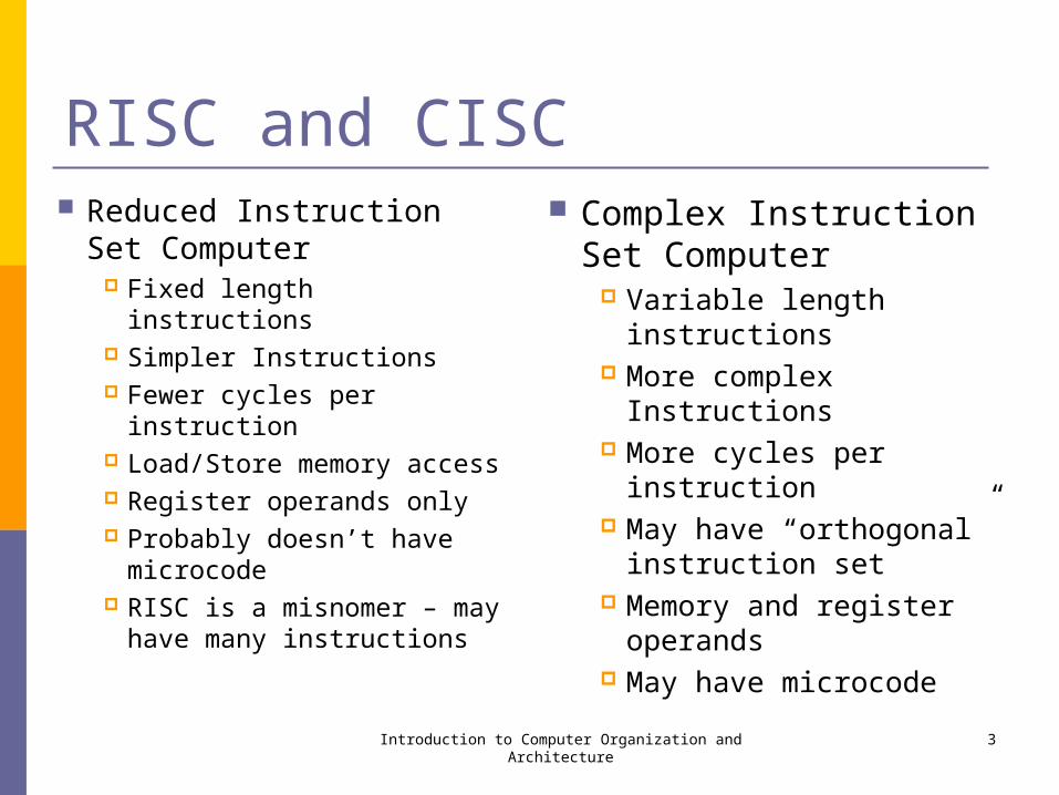
RISC and CISC Reduced Instruction Set
Computer Fixed length instructions Simpler Instructions Fewer cycles per
instruction Load/Store memory
access Register operands only Probably doesn’t have
microcode RISC is a misnomer – may
have many instructions
Complex Instruction Set Computer
Variable length instructions More complex Instructions More cycles per instruction May have “orthogonal”
instruction set Memory and register
operands May have microcode
Introduction to Computer Organization and Architecture 3
ARM “Advanced RISC Machines” www.arm.com Over 90 ARM processors are shipped every
second – more than any other 32-bit processor IP supplier
ARM licenses its technology to more than 200 semiconductor companies.
Eight product families
Introduction to Computer Organization and Architecture 4
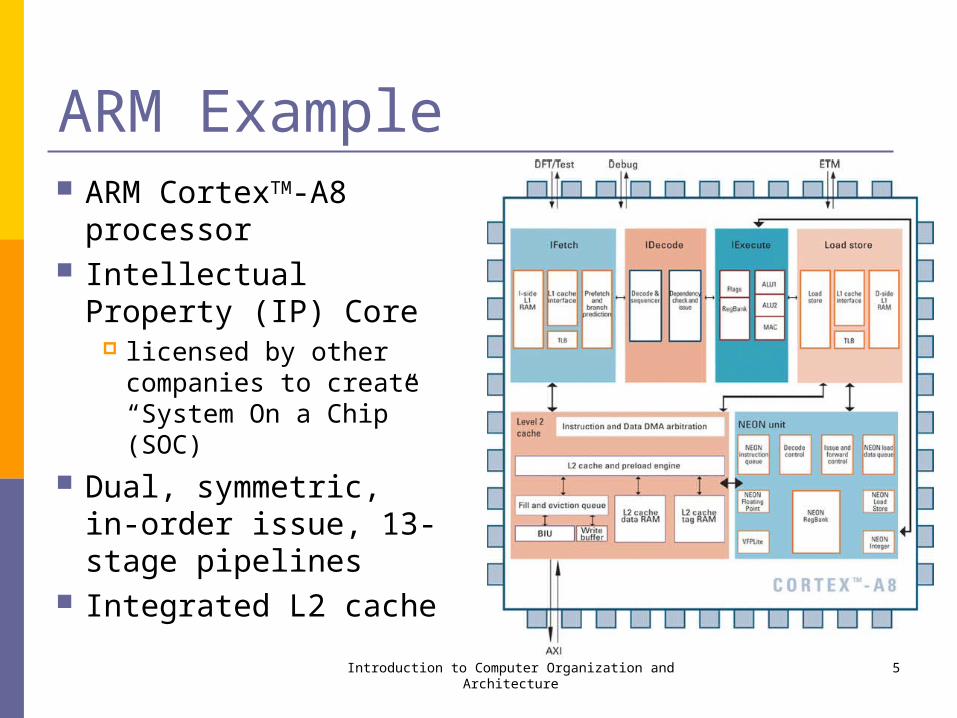
ARM Example ARM CortexTM-A8
processor Intellectual Property (IP)
Core licensed by other
companies to create “System On a Chip” (SOC)
Dual, symmetric, in-order issue, 13-stage pipelines
Integrated L2 cacheIntroduction to Computer Organization and Architecture 5
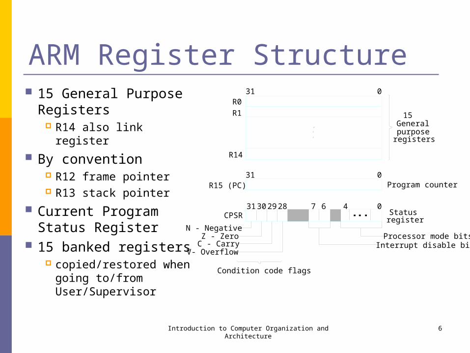
ARM Register Structure 15 General Purpose
Registers R14 also link register
By convention R12 frame pointer R13 stack pointer
Current Program Status Register
15 banked registers copied/restored when
going to/from User/Supervisor
Introduction to Computer Organization and Architecture 6
31 29 7 0
Program counter
R0
R1
31 0
R14
31 0
Status28
R15 (PC)
30 6 4CPSR
N - NegativeZ - Zero
C - CarryV- Overflow
Condition code flags
Processor mode bits
register
Interrupt disable bits
Generalpurposeregisters
15

ARM Instruction Format
Load/store architecture (RISC) Conditional execution of instructions One or two operands (register) Destination register See appendix B
Introduction to Computer Organization and Architecture 7
Condition
31
OP code
28 27 20 19 16 15 12 11 4 3 0
Rn Rd Other info Rm
ARM Addressing Modes
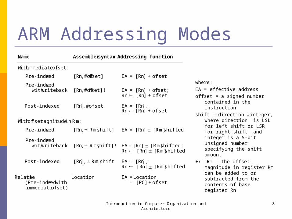
where:
EA = effective address
offset = a signed number contained in the instruction
shift = direction #integer, where direction is LSL for left shift or LSR for right shift, and integer is a 5-bit unsigned number specifying the shift amount
+/- Rm = the offset magnitude in register Rm can be added to or subtracted from the contents of base register Rn
Introduction to Computer Organization and Architecture 8
Name Assembler syntax Addressing function
With immediate of fset:
Pre-inde xed [Rn, #offset] EA = [Rn] + of fset
Pre-inde xedwith writeback [Rn, #offset]! EA = [Rn] + of fset;
Rn [Rn] + of fset
Post-indexed [Rn], #offset EA = [Rn];Rn [Rn] + of fset
With of fset magnitude in Rm:
Pre-inde xed [Rn, Rm , shift] EA = [Rn] [Rm] shifted
Pre-inde xedwith writeback [Rn, Rm , shift]! EA= [Rn] [Rm] shifted;
Rn [Rn] [Rm] shifted
Post-indexed [Rn], Rm , shift EA = [Rn];Rn [Rn] [Rm] shifted
Relati ve Location EA = Location(Pre-inde xed with = [PC] + of fsetimmediate of fset)

ARM Relative Addressing Mode LDR R1,ITEM
Pre-indexed mode with immediate offset
PC is base register Calculated offset = 52
PC will be at 1008 when executed
Introduction to Computer Organization and Architecture 9
52 = offset
1000
word (4 bytes)
ITEM = 1060 Operand
Memory address
updated [PC] = 1008
***
***
LDR R1, ITEM
1004
1008 -
-
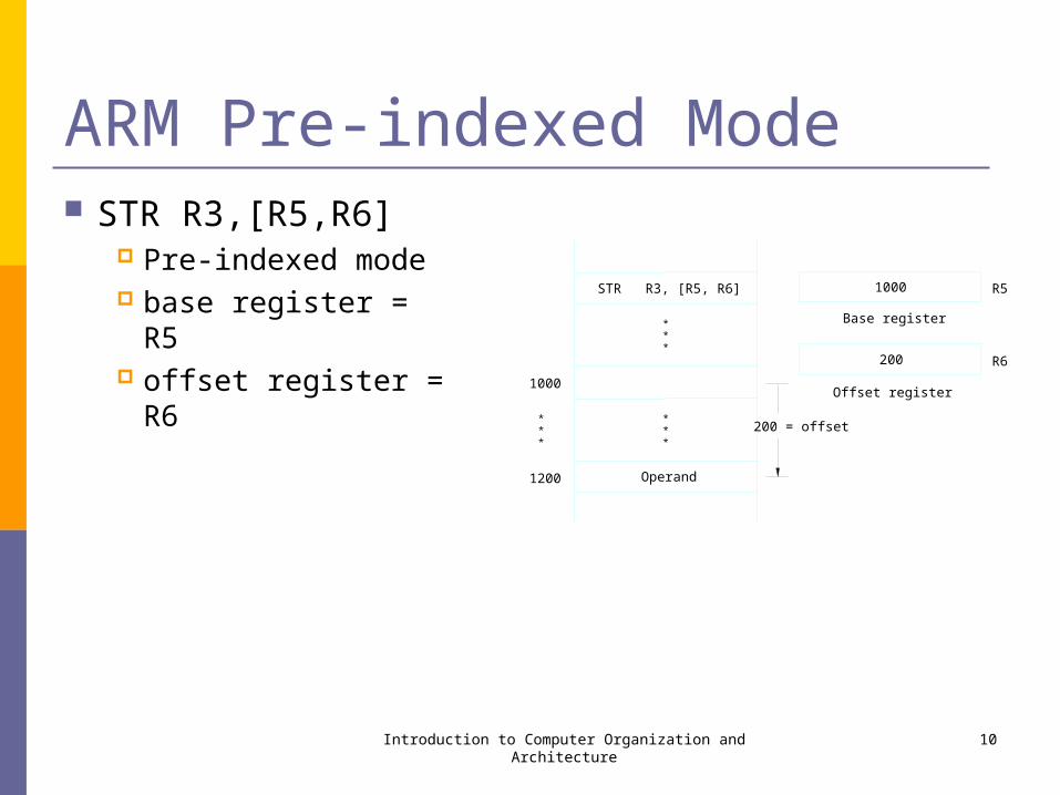
ARM Pre-indexed Mode STR R3,[R5,R6]
Pre-indexed mode base register = R5 offset register = R6
Introduction to Computer Organization and Architecture 10
1000
200 = offset
1000
1200
Base register
200
Offset register
***
***
***
STR R3, [R5, R6] R5
R6
Operand
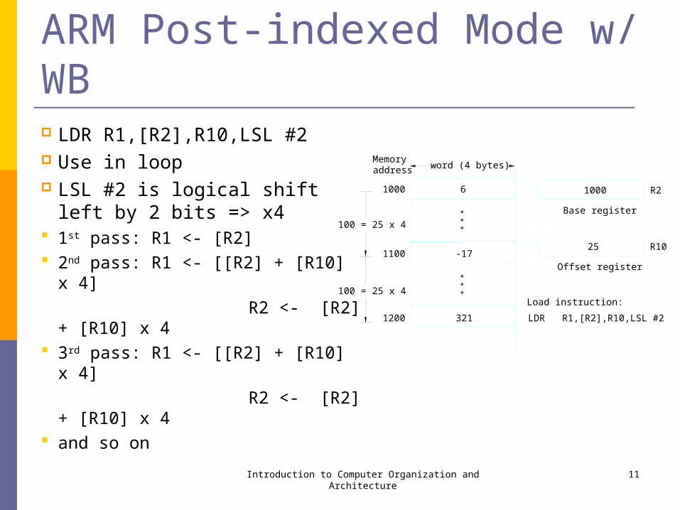
ARM Post-indexed Mode w/ WB LDR R1,[R2],R10,LSL #2 Use in loop LSL #2 is logical shift left by 2 bits
=> x4 1st pass: R1 <- [R2] 2nd pass: R1 <- [[R2] + [R10] x 4]
R2 <- [R2] + [R10] x 4 3rd pass: R1 <- [[R2] + [R10] x 4]
R2 <- [R2] + [R10] x 4 and so on
Introduction to Computer Organization and Architecture 11
100 = 25 x 4
1000
word (4 bytes)
25
Base register***
6
1100
R2
-17
***
3211200
100 = 25 x 4
1000
Offset register
R10
Memoryaddress
Load instruction:
LDR R1,[R2],R10,LSL #2
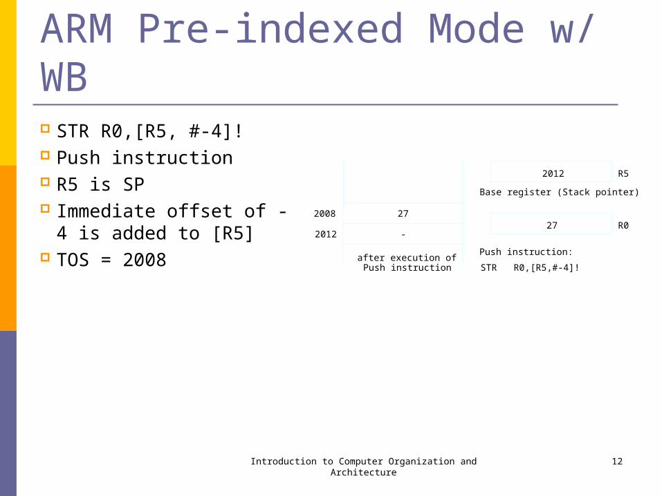
ARM Pre-indexed Mode w/ WB STR R0,[R5, #-4]! Push instruction R5 is SP Immediate offset of -4 is
added to [R5] TOS = 2008
Introduction to Computer Organization and Architecture 12
2008
2012
Base register (Stack pointer)
R0
R5
2727
-2012
after execution ofPush instruction
Push instruction:
STR R0,[R5,#-4]!
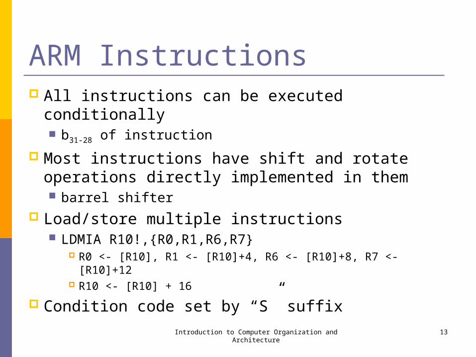
ARM Instructions All instructions can be executed conditionally
b31-28 of instruction
Most instructions have shift and rotate operations directly implemented in them barrel shifter
Load/store multiple instructions LDMIA R10!,{R0,R1,R6,R7}
R0 <- [R10], R1 <- [R10]+4, R6 <- [R10]+8, R7 <- [R10]+12 R10 <- [R10] + 16
Condition code set by “S” suffixIntroduction to Computer Organization and Architecture 13
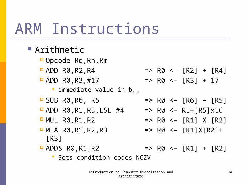
ARM Instructions Arithmetic
Opcode Rd,Rn,Rm ADD R0,R2,R4 => R0 <- [R2] + [R4] ADD R0,R3,#17 => R0 <- [R3] + 17
immediate value in b7-0
SUB R0,R6, R5 => R0 <- [R6] – [R5] ADD R0,R1,R5,LSL #4 => R0 <- R1+[R5]x16 MUL R0,R1,R2 => R0 <- [R1] X [R2] MLA R0,R1,R2,R3 => R0 <- [R1]X[R2]+[R3] ADDS R0,R1,R2 => R0 <- [R1] + [R2]
Sets condition codes NCZV
Introduction to Computer Organization and Architecture 14
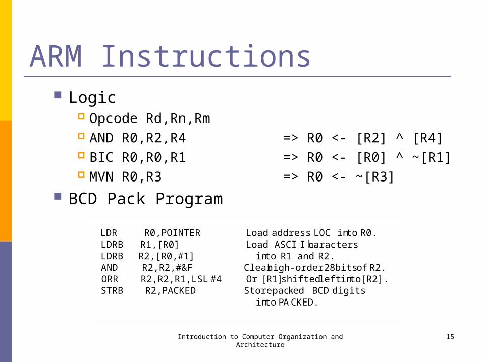
ARM Instructions Logic
Opcode Rd,Rn,Rm AND R0,R2,R4 => R0 <- [R2] ^ [R4] BIC R0,R0,R1 => R0 <- [R0] ^ ~[R1] MVN R0,R3 => R0 <- ~[R3]
BCD Pack Program
Introduction to Computer Organization and Architecture 15
LDR R0,POINTER Load address LOC into R0.LDRB R1,[R0] Load ASCI I charactersLDRB R2,[R0,#1] into R1 and R2.AND R2,R2,#&F Clearhigh-order 28 bits of R2.ORR R2,R2,R1,LSL #4 Or [R1] shifted left into [R2].STRB R2,PACKED Store packed BCD digits
into PACKED.
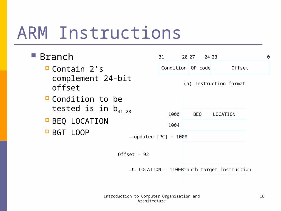
ARM Instructions Branch
Contain 2’s complement 24-bit offset
Condition to be tested is in b31-28
BEQ LOCATION BGT LOOP
Introduction to Computer Organization and Architecture 16
Condition
31
OP code
28 27
Offset
24 23 0
(a) Instruction format
1000
LOCATION = 1100
BEQ LOCATION
Branch target instruction
1004
updated [PC] = 1008
Offset = 92
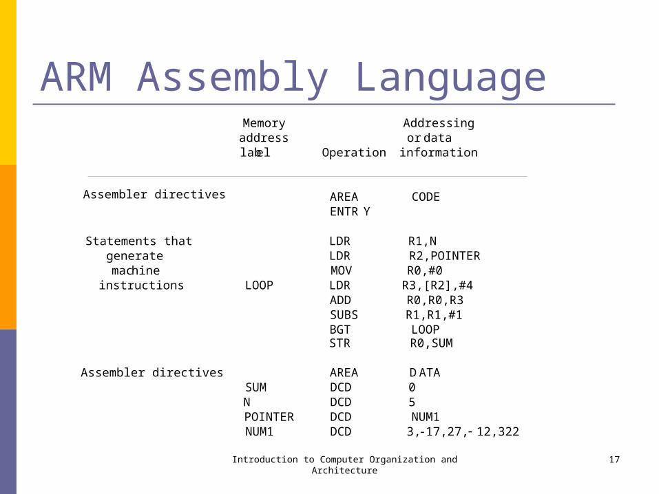
ARM Assembly Language
Introduction to Computer Organization and Architecture 17
Memory Addressingaddress or datalabel Operation information
AREA CODEENTR Y
Statements that LDR R1,Ngenerate LDR R2,POINTERmachine MOV R0,#0instructions LOOP LDR R3,[R2],#4
ADD R0,R0,R3SUBS R1,R1,#1BGT LOOPSTR R0,SUM
Assembler directives AREA DATASUM DCD 0N DCD 5POINTER DCD NUM1NUM1 DCD 3, 17,27, 12,322
Assembler directives
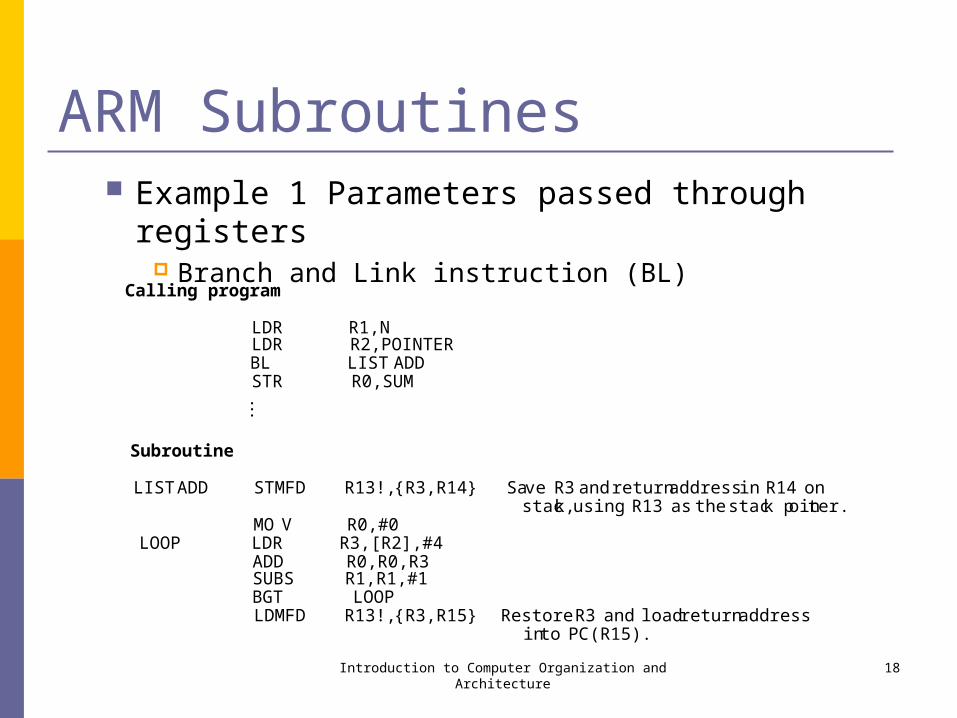
ARM Subroutines Example 1 Parameters passed through registers
Branch and Link instruction (BL)
Introduction to Computer Organization and Architecture 18
Calling program
LDR R1,NLDR R2,POINTERBL LIST ADDSTR R0,SUM...
Subroutine
LISTADD STMFD R13!,{R3,R14} Save R3and returnaddress in R14 onstack, using R13 as the stack pointer.
MO V R0,#0LOOP LDR R3,[R2],#4
ADD R0,R0,R3SUBS R1,R1,#1BGT LOOPLDMFD R13!,{R3,R15 } Restore R3 and load return address
into PC (R15).
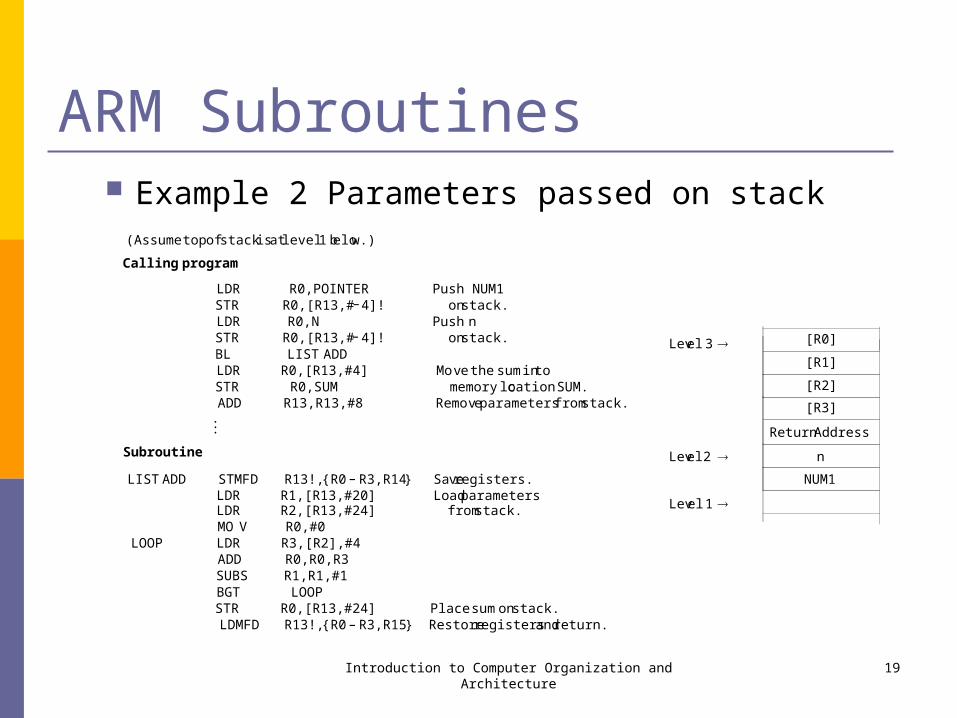
ARM Subroutines Example 2 Parameters passed on stack
Introduction to Computer Organization and Architecture 19
[R0]
[R1]
[R2]
[R3]
ReturnAddress
n
NUM1
Level 3
Level2
Level 1
(Assumetopofstackisat level1 below.)
Callingprogram
LDR R0,POINTER Push NUM1STR R0,[R13,# 4]! onstack.LDR R0,N Push nSTR R0,[R13,# 4]! onstack.BL LIST ADDLDR R0,[R13,#4] Move thesumintoSTR R0,SUM memorylocation SUM.ADD R13,R13,#8 Removeparametersfromstack....
Subroutine
LIST ADD STMFD R13!,{R0 R3,R14} Saveregisters.LDR R1,[R13,#20] LoadparametersLDR R2,[R13,#24] fromstack.MOV R0,#0
LOOP LDR R3,[R2],#4ADD R0,R0,R3SUBS R1,R1,#1BGT LOOPSTR R0,[R13,#24] Placesumonstack.LDMFD R13!,{R0 R3,R15} Restoreregistersandreturn.
–
–
–
–

ARM Program Example Byte sorting program
C program Assembly program
Introduction to Computer Organization and Architecture 20
for (j = n 1; j > 0; j = j 1){for ( k = j 1; k>= 0; k = k 1 )
{ if (LIST[k]> LIST[j] ){ TEMP = LIST[k];
LIST[k]= LIST[ j];LIST[ j]= TEMP;
}}
}
–––
–ADR R4,LIST Load list pointerregisterR4,LDR R10,N andinitializeouter loopbaseADD R2,R4,R10 registerR2 to LIST + n.ADD R5,R4,#1 Load LIST + 1 into R5.
OUTER LDRB R0,[R2,# 1]! Load LIST( j ) into R0.MOV R3,R2 Initializeinner loopbaseregister
R3 to LIST + n 1.INNER LDRB R1,[R3,# 1]! Load LIST( k) into R1.
CMP R1,R0 Compare LIST(k) to LIST( j).STRGTB R1,[R2] If LIST( k) > LIST( j ), swapSTRGTB R0,[R3] LIST( k) and LIST( j ), andMOVGT R0,R1 move(new) LIST( j ) into R0.CMP R3,R4 If k > 0,repeatBNE INNER inner loop.CMP R2,R5 If j > 1, repeatBNE OUTER outerloop.
–
––

Freescale 68K Freescale Semiconductor
formerly Motorola Semiconductor
www.freescale.com There are more than 17 billion Freescale
semiconductors at work all over the planet. Automobiles, computer networks, communications
infrastructure, office buildings, factories, industrial equipment, tools, mobile phones, home appliances and consumer products
About 20 microprocessor familiesIntroduction to Computer Organization and Architecture 21
68K 68K Family
68000: Introduced in 1979, 16 bit word length and 8/16/32 bit arithmetic, 24 bit address space (16 MB)
68008: 8 bit version of the 68000 with 20 bit address space 68010: Version of the 68000 supporting virtual memory and
virtual machine concepts 68020: Extended addressing capabilities, 32-bit, i-cache 68030: Data cache in addition to the instruction cache, on-
chip memory management unit 68040: Floating-point arithmetic, pipelining, . . . “ColdFire” family added in 1994
V1 through V5 cores
Introduction to Computer Organization and Architecture 22
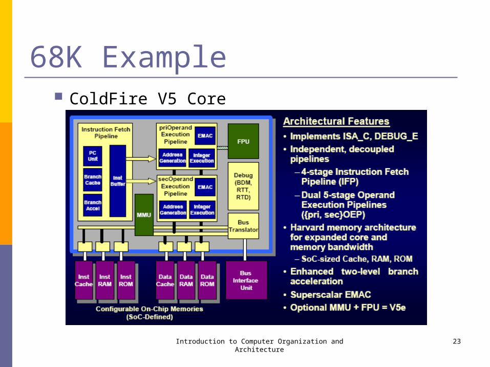
68K Example ColdFire V5 Core
Introduction to Computer Organization and Architecture 23
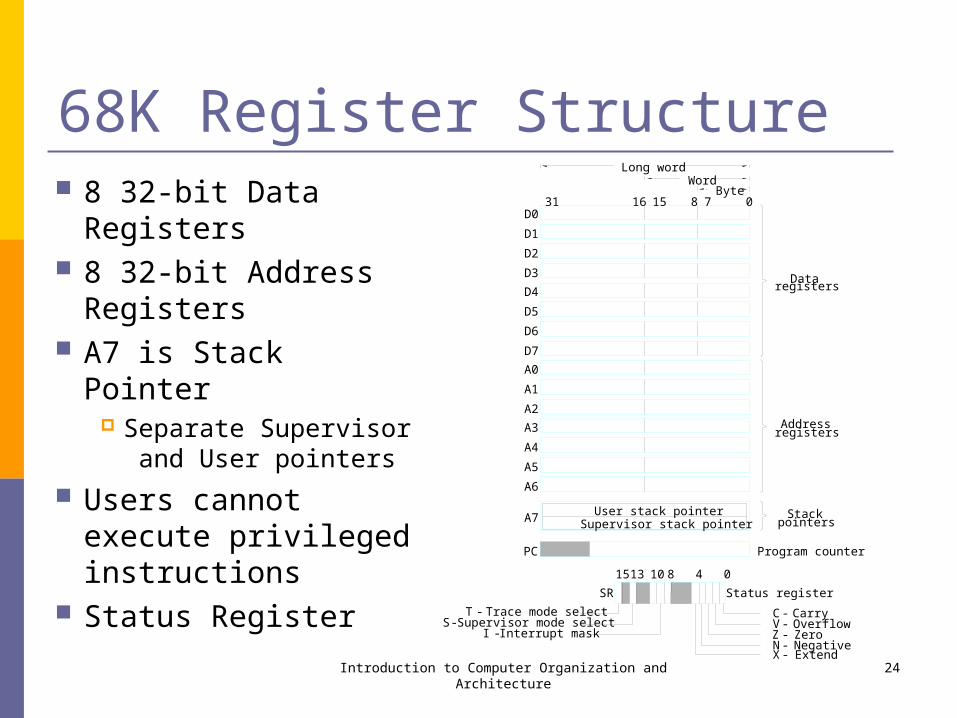
68K Register Structure 8 32-bit Data Registers 8 32-bit Address
Registers A7 is Stack Pointer
Separate Supervisor and User pointers
Users cannot execute privileged instructions
Status Register
Introduction to Computer Organization and Architecture 24
WordByte
Supervisor stack pointer
Long word
User stack pointer
PC
31 15 7 0816
Program counter
pointersStack
registersData
registersAddress
D0
D1
D2
D3
D4
D5
D6
D7
A0
A1
A2
A3
A4
A5
A6
A7
15 13 10 8 4 0
SR Status register
CarryOverflowZeroNegativeExtend
Trace mode selectSupervisor mode select
Interrupt mask
-T-S
-I
-X
-Z-N
-V-C
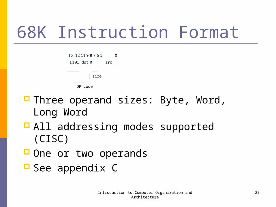
68K Instruction Format
Three operand sizes: Byte, Word, Long Word All addressing modes supported (CISC) One or two operands See appendix C
Introduction to Computer Organization and Architecture 25
src1011 dst 0
OP code
size
58111215 9 7 6 0

68K Addressing Modes
where:
EA = effective address
Value = a number given either explicitly or represented by a label
BValue = an 8-bit Value
WValue = a 16-bit Value
An = an address register
Rn = an address or a data register
S = a size indicator
Introduction to Computer Organization and Architecture 26
Name Assemblersyntax Addressingfunction
Immediate #Value Operand= Value
AbsoluteShort Value EA = SignExtended WValue
AbsoluteLong Value EA = Value
Register Rn EA = Rn
that is, Operand = [Rn ]
RegisterIndirect (An) EA = [An ]
Autoincrement (An)+ EA = [An ];Increment An
Autodecrement (An) Decrement An ;EA = [An ]
Indexedbasic WValue(An) EA = WValue + [An ]
Indexedfull BValue(An,Rk.S) EA = BValue + [An ] +[Rk ]
Relativebasic WValue(PC) EA = WValue + [PC]or Label
Relative full BValue(PC,Rk.S) EA = BValue + [PC] + [Rk ]or Label (Rk)
–
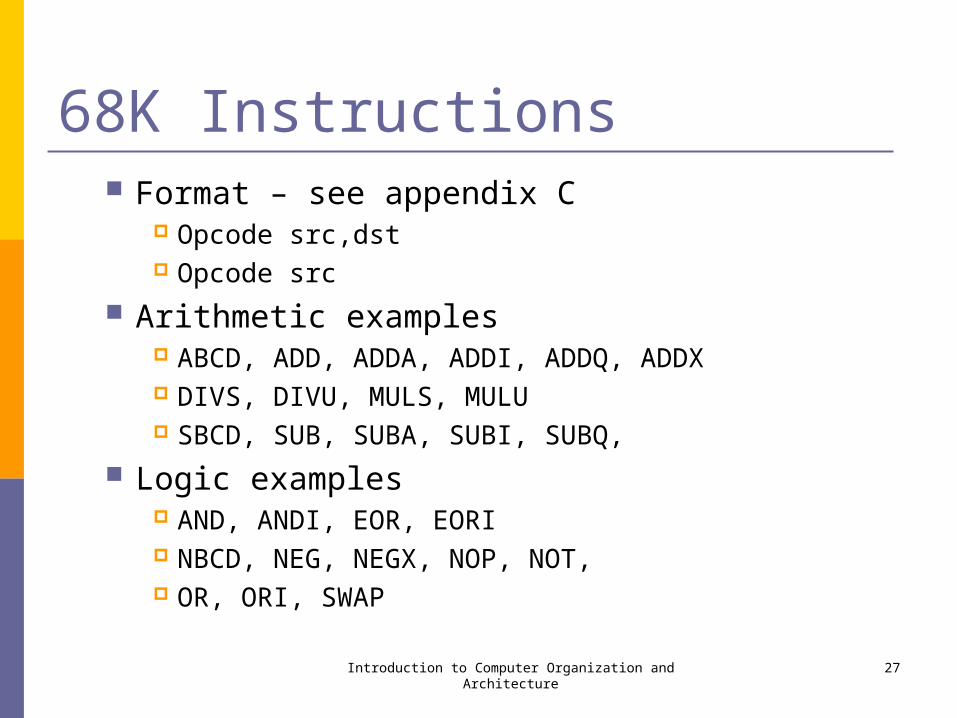
68K Instructions Format – see appendix C
Opcode src,dst Opcode src
Arithmetic examples ABCD, ADD, ADDA, ADDI, ADDQ, ADDX DIVS, DIVU, MULS, MULU SBCD, SUB, SUBA, SUBI, SUBQ,
Logic examples AND, ANDI, EOR, EORI NBCD, NEG, NEGX, NOP, NOT, OR, ORI, SWAP
Introduction to Computer Organization and Architecture 27
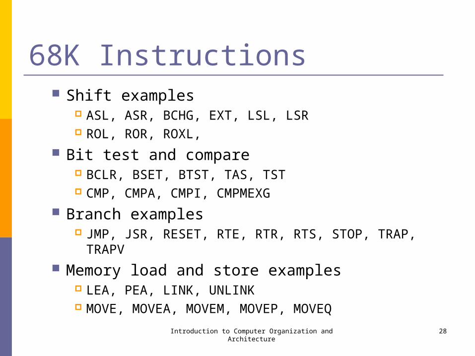
68K Instructions Shift examples
ASL, ASR, BCHG, EXT, LSL, LSR ROL, ROR, ROXL,
Bit test and compare BCLR, BSET, BTST, TAS, TST CMP, CMPA, CMPI, CMPMEXG
Branch examples JMP, JSR, RESET, RTE, RTR, RTS, STOP, TRAP, TRAPV
Memory load and store examples LEA, PEA, LINK, UNLINK MOVE, MOVEA, MOVEM, MOVEP, MOVEQ
Introduction to Computer Organization and Architecture 28
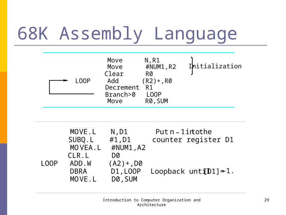
68K Assembly Language
Introduction to Computer Organization and Architecture 29
R0Clear
R0,SUM
R1(R2)+,R0
Initialization
Move
LOOP AddDecrement
LOOP
#NUM1,R2N,R1Move
Move
Branch>0
MOVE.L N,D1 Put n 1 intotheSUBQ.L #1,D1 counter register D1MOVEA.L #NUM1,A2CLR.L D0
LOOP ADD.W (A2)+,D0DBRA D1,LOOP Loopback until[D1]=–1.MOVE.L D0,SUM
–
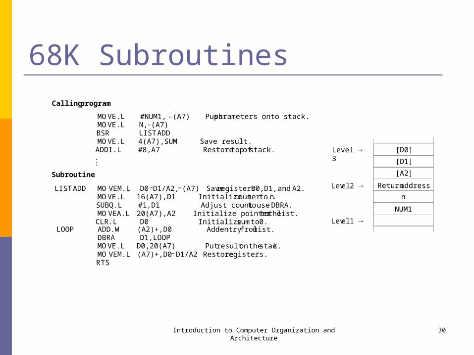
68K Subroutines
Introduction to Computer Organization and Architecture 30
[D0]
[D1]
[A2]
Returnaddress
n
NUM1
Level 3
Level2
Level1
Callingprogram
MOVE.L #NUM1, (A7) Pushparameters onto stack.MOVE.L N, (A7)BSR LISTADDMOVE.L 4(A7),SUM Save result.ADDI.L #8,A7 Restoretopofstack....
Subroutine
LISTADD MOVEM.L D0 D1/A2, (A7) SaveregistersD0,D1,and A2.MOVE.L 16(A7),D1 Initializecounter to n.SUBQ.L #1,D1 Adjust countto useDBRA.MOVEA.L 20(A7),A2 Initialize pointertothelist.CLR.L D0 Initializesumto 0.
LOOP ADD.W (A2)+,D0 Addentryfromlist.DBRA D1,LOOPMOVE.L D0,20(A7) Put resulton thestack.MOVEM.L (A7)+,D0 D1/A2 Restoreregisters.RTS
–
–
–
–
–

68K Program Example Byte sorting program
C program Assembly program
Introduction to Computer Organization and Architecture 31
for (j = n 1; j > 0; j = j 1){for ( k = j 1; k>= 0; k = k 1 )
{ if (LIST[k]> LIST[j] ){ TEMP = LIST[k];
LIST[k]= LIST[ j];LIST[ j]= TEMP;
}}
}
–––
–MOVEA.L #LIST,A1 Pointertothestartofthe list.MOVE N,D1 Initializeouter loopSUBQ #1,D1 indexj in D1.
OUTER MOVE D1,D2 InitializeinnerloopSUBQ #1,D2 indexk in D2.MOVE.B (A1,D1),D3 Currentmaximum value in D3.
INNER CMP.B D3,(A1,D2) If LIST( k) [D3],BLE NEXT donotexchange.MOVE.B (A1,D2),(A1,D1) Interchange LIST(k)MOVE.B D3,(A1,D2) andLIST( j) andloadMOVE.B (A1,D1),D3 newmaximum into D3.
NEXT DBRA D2,INNER Decrement counters k and jSUBQ #1,D1 andbranch backBGT OUTER if notfinished.
IA-32 Intel Corporation www.intel.com developer.intel.com Microprocessor used in PCs and Apple computers Processor Families
Desktop processors Server and workstation processors Internet device processors Notebook processors Embedded and communications processors
Introduction to Computer Organization and Architecture 32
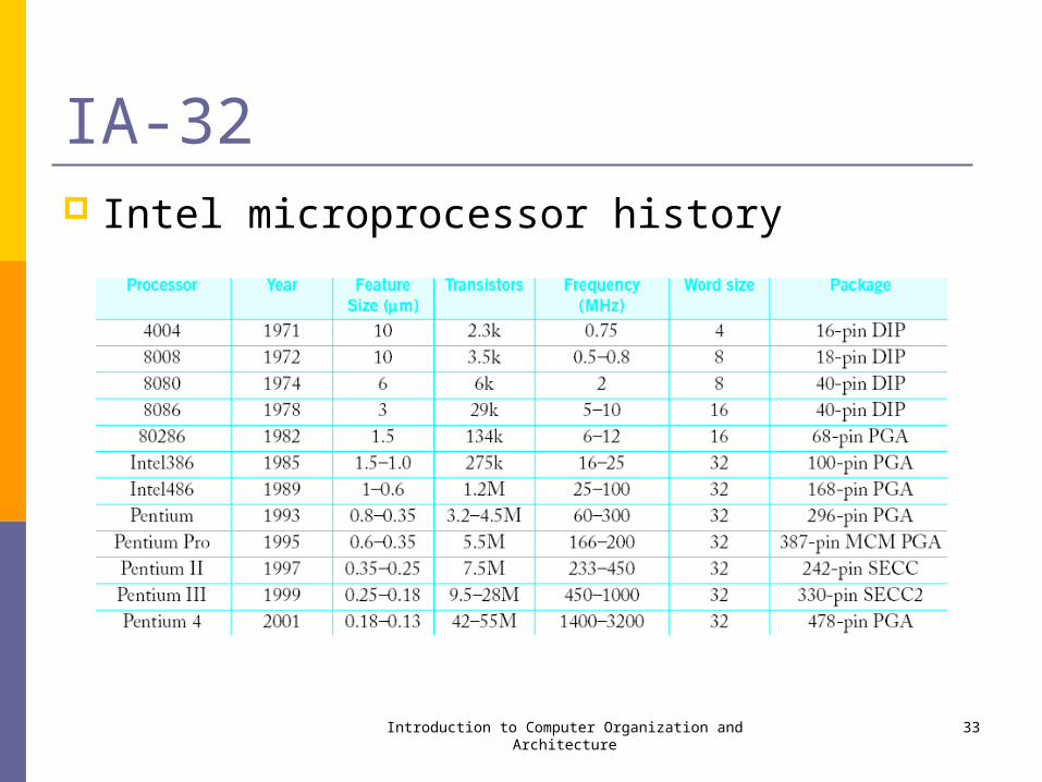
IA-32 Intel microprocessor history
Introduction to Computer Organization and Architecture 33
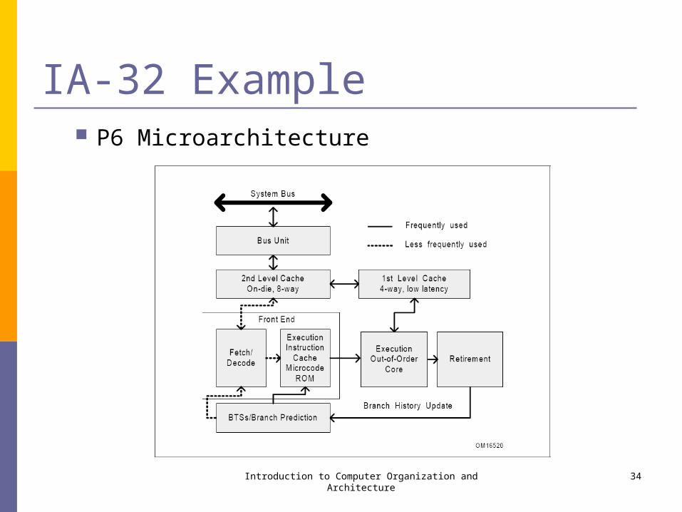
IA-32 Example P6 Microarchitecture
Introduction to Computer Organization and Architecture 34
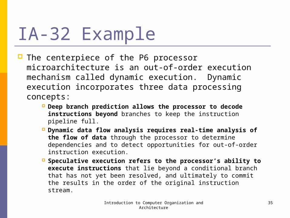
IA-32 Example The centerpiece of the P6 processor microarchitecture
is an out-of-order execution mechanism called dynamic execution. Dynamic execution incorporates three data processing concepts:
Deep branch prediction allows the processor to decode instructions beyond branches to keep the instruction pipeline full.
Dynamic data flow analysis requires real-time analysis of the flow of data through the processor to determine dependencies and to detect opportunities for out-of-order instruction execution.
Speculative execution refers to the processor’s ability to execute instructions that lie beyond a conditional branch that has not yet been resolved, and ultimately to commit the results in the order of the original instruction stream.
Introduction to Computer Organization and Architecture 35
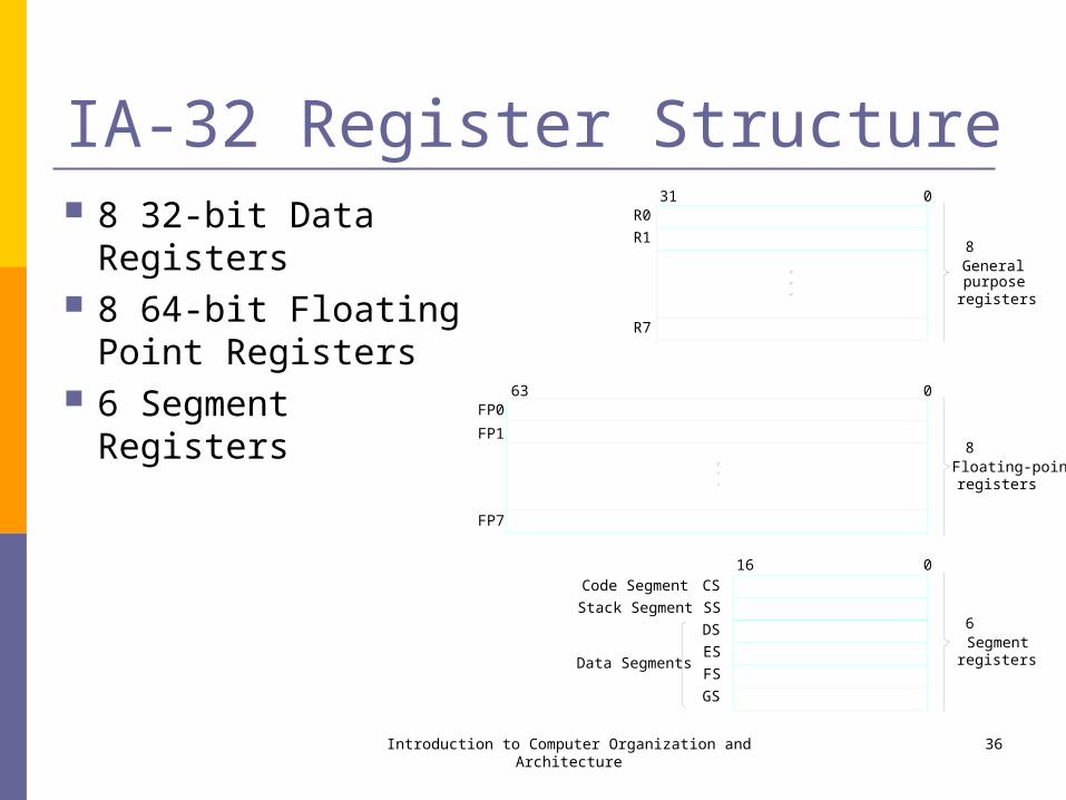
IA-32 Register Structure 8 32-bit Data Registers 8 64-bit Floating Point
Registers 6 Segment Registers
Introduction to Computer Organization and Architecture 36
R0
R1
31 0
R7
FP0
FP1
FP7
63 0
CS
16 0
SS
ES
FS
GS
DS
Code Segment
Stack Segment
Data Segments
Generalpurposeregisters
8
Floating-pointregisters
8
Segmentregisters
6
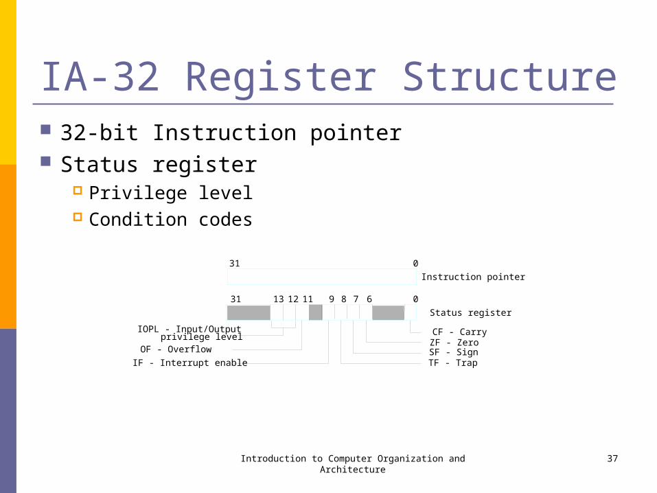
IA-32 Register Structure 32-bit Instruction pointer Status register
Privilege level Condition codes
Introduction to Computer Organization and Architecture 37
31 13 11 9 7 0
Instruction pointer
CF - CarryZF - ZeroSF - SignTF - Trap
IOPL - Input/Output
OF - Overflow
IF - Interrupt enable
31 0
Status register
12 8 6
privilege level
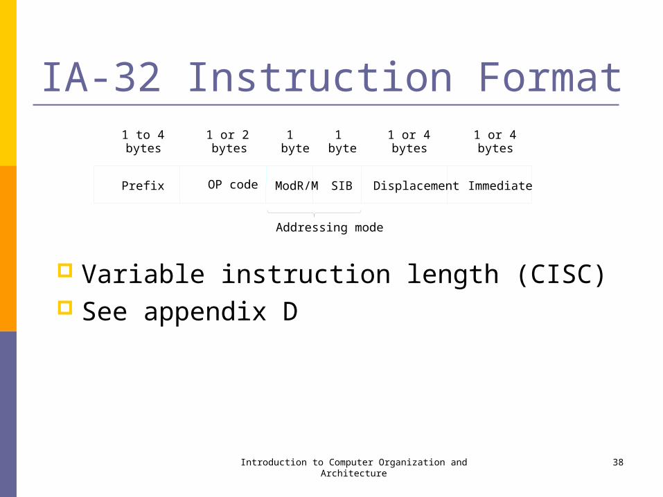
IA-32 Instruction Format
Variable instruction length (CISC) See appendix D
Introduction to Computer Organization and Architecture 38
Prefix
1 to 4
OP code ModR/M SIB Displacement Immediate
bytes1 or 2bytes
1byte
1 or 4bytes
1byte
1 or 4bytes
Addressing mode

IA-32 Addressing Modes
where:
Value = an 8- or 32-bit signed number
Location = a 32-bit address
Reg, Reg1, Reg2 = one of the general purpose registers EAX, EBX, ECX, EDX, ESP, EBP, ESI, EDI, with the exception that ESP cannot be used as an index register
Disp = an 8- or 32-bit signed number, except that in the Index with displacement mode it can only be 32 bits
S = scale factor of 1, 2, 4, or 8
Introduction to Computer Organization and Architecture 39
Name Assembler syntax Addressing function
Immediate Value Operand= Value
Direct Location EA= Location
Register Reg EA =Regthatis,Operand=[Reg]
Registerindirect [Reg] EA = [Reg]
Basewith [Reg+Disp] EA = [Reg]+Dispdisplacement
Indexwith [Reg S + Disp] EA = [Reg] S +Dispdisplacement
Basewithindex [Reg1+Reg2 * S] EA = [Reg1]+[Reg2] S
Basewithindex [Reg1+Reg2 * S + Disp] EA = [Reg1]+[Reg2] S+Dispanddisplacement
*
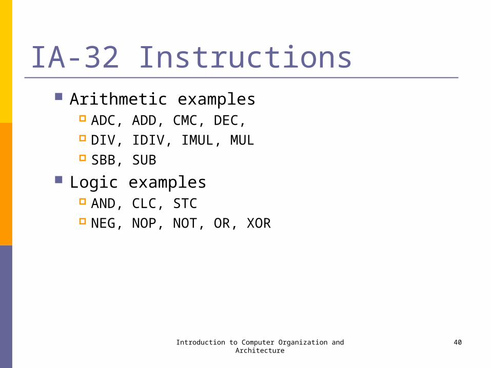
IA-32 Instructions Arithmetic examples
ADC, ADD, CMC, DEC, DIV, IDIV, IMUL, MUL SBB, SUB
Logic examples AND, CLC, STC NEG, NOP, NOT, OR, XOR
Introduction to Computer Organization and Architecture 40
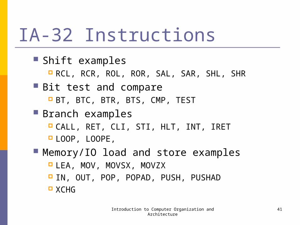
IA-32 Instructions Shift examples
RCL, RCR, ROL, ROR, SAL, SAR, SHL, SHR
Bit test and compare BT, BTC, BTR, BTS, CMP, TEST
Branch examples CALL, RET, CLI, STI, HLT, INT, IRET LOOP, LOOPE,
Memory/IO load and store examples LEA, MOV, MOVSX, MOVZX IN, OUT, POP, POPAD, PUSH, PUSHAD XCHG
Introduction to Computer Organization and Architecture 41

IA-32 Assembly Language
Introduction to Computer Organization and Architecture 42
Assembler directives
.dataNUM1 DD 17, 3,51,242, 113N DD 5SUM DD 0
.code
Statements that generatemachine instructions
MAIN : LEA EBX ,NUM1SUB EBX ,4MOV ECX ,NMOV EAX , 0
STARTADD : ADD EAX , [EBX+ECX 4]LOOP STARTADDMOV SUM,EAX
Assembler directives END MAIN
*
IA-32 Subroutines
Introduction to Computer Organization and Architecture 43
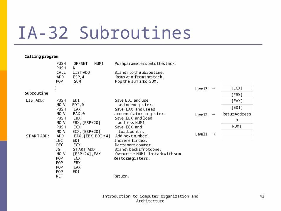
Callingprogram
PUSH OFFSET NUM1 Pushparametersonto the stack.PUSH NCALL LIST ADD Branch to thesubroutine.ADD ESP,4 Remove n from the stack.POP SUM Pop the sum into SUM....
Subroutine
LIST ADD: PUSH EDI Save EDI and useMO V EDI,0 as indexregister.PUSH EAX Save EAX and useasMO V EAX,0 accummulator register.PUSH EBX Save EBX and loadMO V EBX,[ESP+20] address NUM1.PUSH ECX Save ECX andMO V ECX,[ESP+20] loadcount n.
STARTADD: ADD EAX,[EBX+EDI 4] Add next number.INC EDI Increment index.DEC ECX Decrement counter.JG START ADD Branch back if not done.MO V [ESP+24],EAX Overwrite NUM1 in stack with sum.POP ECX Restoreregisters.POP EBXPOP EAXPOP EDIRET Return.
*
[ECX]
[EBX]
[EAX]
[EDI]
ReturnAddress
n
NUM1
Level3
Level2
Level1

IA-32 Program Example Byte sorting program
C program Assembly program
Introduction to Computer Organization and Architecture 44
for (j = n 1; j > 0; j = j 1){for ( k = j 1; k>= 0; k = k 1 )
{ if (LIST[k]> LIST[j] ){ TEMP = LIST[k];
LIST[k]= LIST[ j];LIST[ j]= TEMP;
}}
}
–––
–LEA EAX,LIST Loadlist pointerbaseMOV EDI,N register(EAX),andinitializeDEC EDI outer loopindexregister
(EDI) to j=n 1.OUTER: MOV ECX,EDI Initializeinnerloopindex
DEC ECX register(ECX) to k= j 1.MOV DL,[EAX+EDI] Load LIST(j) intoregisterDL.
INNER: CMP [EAX +ECX],DL CompareLIST(k) to LIST(j).JLE NEXT If LIST(k) LIST(j), goto
next lower kindexentry;XCHG [EAX+ECX],DL Otherwise, interchange LIST(k)
and LIST(j), leavingMOV [EAX+EDI],DL newLIST(j) in DL.
NEXT: DEC ECX Decrement inner loop index k.JGE INNER Repeat or terminate inner loop.DEC EDI Decrement outer loop index j.JG OUTER Repeat or terminate outer loop.
–
–

The End Lecture 5