introduction to fluidized beds - engineering …€, chemical engineering science, 55, 4789-4825....
TRANSCRIPT

INTRODUCTION TO
FLUIDIZED BEDS
CHEMICAL REACTION ENGINEERING LABORATORY

Outline/Contents
Introduction.
Fluidization Flow Regimes.
Overall Gas (Voidage) and solids Hold-up.
Radial and Axial Solids Hold-Up Profiles.
Radial and Axial voidage distribution.
Gas and Solid Mixing.
Scale-Up.
Reactor Modeling.
CHEMICAL REACTION ENGINEERING LABORATORY

Fluidized Bed Reactor Components
CHEMICAL REACTION ENGINEERING LABORATORY
The material fluidized is a solid (catalyst).
The fluidizing medium is either
a gas or a liquid.
Gas distributor
Inlet to cyclone

Advantages Disadvantages
It has the ability to process large volumes of fluid.
Excellent gas-solid contacting.
Heat and mass transfer rates between gas and particles are high when compared with other modes of contacting.
No hot spot even with highly exothermic reaction.
Ease of solids handling.
CHEMICAL REACTION ENGINEERING LABORATORY
Broad or even bimodal
residence time
distribution of the gas
due to dispersion and
bypass in the form of
bubbles.
Broad residence time
distribution of solids due
to intense solids mixing.
Erosion of internals.
Attrition of catalyst
particles.
Difficult Scale-up due to
complex hydrodynamics.

Industrial Applications of Fluidized Bed Reactor
Acrylonitrile by the Sohio Process.
Fischer-Tropsch Synthesis.
Phthalic anhydride synthesis.
Methanol to gasoline and olefin processes.
Cracking of Hydrocarbons (Fluid Catalytic Cracking, etc).
Coal combustion.
Coal gasification
Cement clinker production.
Titanium dioxide production.
Calcination of AL(OH)3.
Granulation drying of yeast.
Heat exchange
Absorption
Nuclear energy (Uranium processing, nuclear fuel fabrication,
reprocessing of fuel and waste disposal).
CHEMICAL REACTION ENGINEERING LABORATORY
Yang 2003

Fluidization Flow Regimes
CHEMICAL REACTION ENGINEERING LABORATORY
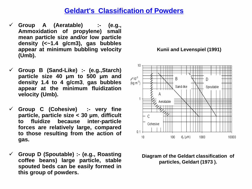
Geldart's Classification of Powders
Group A (Aeratable) :- (e.g., Ammoxidation of propylene) small mean particle size and/or low particle density (<~1.4 g/cm3), gas bubbles appear at minimum bubbling velocity (Umb).
Group B (Sand-Like) :- (e.g.,Starch) particle size 40 μm to 500 μm and density 1.4 to 4 g/cm3, gas bubbles appear at the minimum fluidization velocity (Umb).
Group C (Cohesive) :- very fine particle, particle size < 30 μm, difficult to fluidize because inter-particle forces are relatively large, compared to those resulting from the action of gas.
Group D (Spoutable) :- (e.g., Roasting coffee beans) large particle, stable spouted beds can be easily formed in this group of powders.
3kg
Kunii and Levenspiel (1991)
Diagram of the Geldart classification of
particles, Geldart (1973 ).

Flow Regimes in Fluidized Beds
CHEMICAL REACTION ENGINEERING LABORATORY
J. Ruud van Ommen, 2003

Minimum Fluidization Velocity
mf
75.1
11503
2
fmfps
mf
mfps
mff
fpuDD
ug
This equation can be used to calculate the minimum fluidization velocity
U if the void fraction εmf at incipient fluidization is known.
Experimentally, the most common method of measurement requires that pressure drop
across the bed be recorded as the superficial velocity is increased stepwise through Umf
and beyond, Umf is then taken at the intersection of the straight lines corresponding to
the fixed bed and fluidized bed portions of the graph obtained when is plotted
against U on log-log coordinates. bedP
Kunii and Levenspiel (1991)

Bubbling Fluidization
This type of fluidization has been called ‘aggregative fluidization’, and under these conditions, the bed appears to be divided into two phases, the bubble phase and the emulsion phase.
The bubbles appear to be very similar to gas bubbles formed in a liquid and they behave in a similar manner. The bubbles coalesce as they rise through the bed.
CHEMICAL REACTION ENGINEERING LABORATORY

High solid hold-ups (typically 25-35 %
by volume).
Limited axial mixing of gas.
Suitable for exothermic and fast
reactions.
Good gas-solid contact and hence,
favors reactant conversion.
high gas flow-rates operation and good
for isothermal operation.
Favorable bed to surface heat transfer.
CHEMICAL REACTION ENGINEERING LABORATORY
Turbulent Fluidization
Turbulent regime has the following features:-
Canada et al. 1978

Some commercial processes in turbulent
fluidization
CHEMICAL REACTION ENGINEERING LABORATORY
Process Particle classification Typical gas velocity
(m/s)
FCC regenerators Group A 0.5-1.5
Acrylonitrile Group A ~0.5
Maleic anhydride Group A ~0.5
Phthalic anhydride Group A ~0.5
Ethylene dichloride Group A ~0.5
Roasting of zinc sulfide Group A ~1.5
Bi et al. 2000

Fast Fluidized Bed
The fast fluidization occurs as a result of
continuing increasing in operating velocity
beyond that required at turbulent
fluidization, a critical velocity, commonly
called the transport velocity (Utr), will be
reached where a significant particle
entrainment occurs.
The CFB has significant industrial
applications because of its efficiency,
operational flexibility, and overall
profitability (Berruti et al., 1995).
CHEMICAL REACTION ENGINEERING LABORATORY

Transition between Fluidization Regimes.
Grace (1986a) summarized the effects of particles properties and operating conditions on fluidization behavior and prepared a flow regime diagram. The flow regime diagram was further modified by Kunii and Levenspiel (1997).
For given particles and operating velocity, the gas-solid contact pattern can be determined using this diagram. Likewise, for a given flow regime, this diagram could provide available combinations of particle properties and gas velocity.
Yang 2003

Fluidization diagram
av
s
GsUU
Solid hold-up
Yerushalmi and Cankurt, 1970

Methods for Regime Transition Identification
Several measurement methods have been utilized to
determine the transition from bubbling or slugging to turbulent fluidization which can be classified into three groups:-
Visual Observation,.
Pressure Drop-versus Velocity diagram.
local and overall bed expansion.
Based on signals from pressure transducers, capacitance probes, optical fiber probes, X-ray facilities.
CHEMICAL REACTION ENGINEERING LABORATORY
Bi et al. 2000
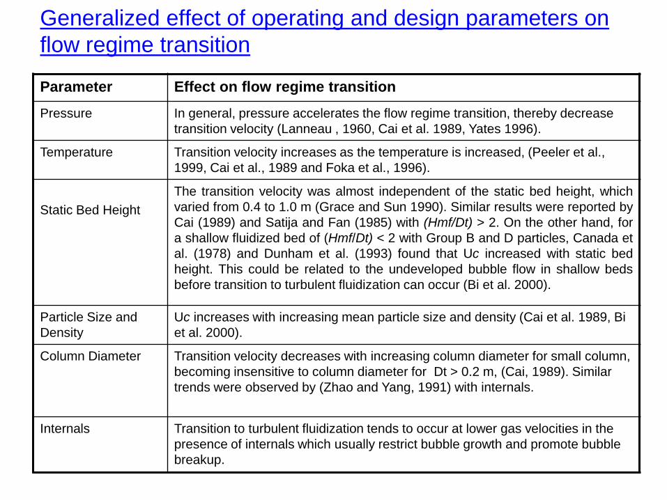
Generalized effect of operating and design parameters on
flow regime transition
Parameter Effect on flow regime transition
Pressure In general, pressure accelerates the flow regime transition, thereby decrease
transition velocity (Lanneau , 1960, Cai et al. 1989, Yates 1996).
Temperature Transition velocity increases as the temperature is increased, (Peeler et al.,
1999, Cai et al., 1989 and Foka et al., 1996).
Static Bed Height
The transition velocity was almost independent of the static bed height, which
varied from 0.4 to 1.0 m (Grace and Sun 1990). Similar results were reported by
Cai (1989) and Satija and Fan (1985) with (Hmf/Dt) > 2. On the other hand, for
a shallow fluidized bed of (Hmf/Dt) < 2 with Group B and D particles, Canada et
al. (1978) and Dunham et al. (1993) found that Uc increased with static bed
height. This could be related to the undeveloped bubble flow in shallow beds
before transition to turbulent fluidization can occur (Bi et al. 2000).
Particle Size and
Density
Uc increases with increasing mean particle size and density (Cai et al. 1989, Bi
et al. 2000).
Column Diameter Transition velocity decreases with increasing column diameter for small column,
becoming insensitive to column diameter for Dt > 0.2 m, (Cai, 1989). Similar
trends were observed by (Zhao and Yang, 1991) with internals.
Internals Transition to turbulent fluidization tends to occur at lower gas velocities in the
presence of internals which usually restrict bubble growth and promote bubble
breakup.

Effect of column diameter
Uc decreases with increasing column diameter for small columns (less than 2 m), becoming insensitive to column diameter for Dt > 0.2 m.
Similar trends were observed by Zhao and Yang (1991) in columns with internals.
CHEMICAL REACTION ENGINEERING LABORATORY
Cai (1989)

Cai et al., 1989, “Effect of operating temperature and pressure on
the transition from bubbling to turbulent fluidization”, AICHE
Symposium series, 85, 37-43.
Chehbouni et al., (1994), “Characterization of the flow transition
between bubbling and turbulent fluidization”, Ind. Eng. Chem. Res.,
33, 1889-1896.
Bi et al., (2000), “A state-of-art review of gas-solid turbulent
fluidization”, Chemical engineering science, 55, 4789-4825.
Andreux et al. (2005), “New description of fluidization regimes”,
AICHE Journal, 51, No.4, 1125-1130.
Some Selected References
CHEMICAL REACTION ENGINEERING LABORATORY