introduction to hdls
TRANSCRIPT

Universität Dortmund
Lab of Digital Electronics M /
Lab of Hardware-Software Design of Embedded Systems
Davide Rossi
DEI University of Bologna
AA 2017-2018
Introduction to HDLs

Universität Dortmund
Purpose of HDLs
• Purpose of Hardware Description Languages:– Capture design in Register Transfer Language form
• i.e. All registers specified
– Use to simulate design so as to verify correctness
– Pass through Synthesis tool to obtain reasonably optimal gate-level design that meets timing
– Design productivity
• Automatic synthesis
• Capture design as RTL instead of schematic
• Reduces time to create gate level design by an order of magnitude
• Synthesis– Basically, a Boolean Combinational Logic optimizer that is timing aware

Universität Dortmund
Type of HDLs
• Digital HDL:– VERILOG
– VHDL
– SYSTEMC
– AHDL (Altera HDL, a proprietary language from Altera)
– …..
• Analog and Mixed Signals:– Verilog AMS
– Verilog A
– Spectre, Spice

Universität Dortmund
Verilog vs. VHDL
• Verilog– Based on C, originally Cadence proprietary, now an IEEE Standard
– Quicker to learn, read and design in than VHDL
– Has more tools supporting its use than VHDL
• VHDL– VHSIC (Very High Speed Integrated Circuit) Hardware Description
Language
– Developed by the Department of Defense, based on ADA
– An IEEE Standard
– More formal than Verilog, e.g. Strong typing
– Has more features than Verilog

Universität Dortmund
History of Verilog
• Developed in 1984: C like language
• Verilog 95, Verilog 2001, Verilog 2005 and
SystemVerilog
• Standard IEEE1364
• Case Sensitive Language
Universität Dortmund
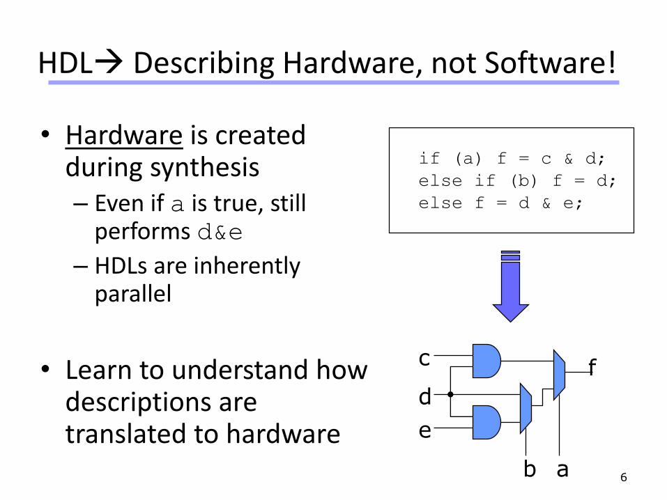
HDL Describing Hardware, not Software!
• Hardware is created during synthesis– Even if a is true, still
performs d&e
– HDLs are inherently parallel
• Learn to understand how descriptions are translated to hardware
6
if (a) f = c & d;
else if (b) f = d;
else f = d & e;
f
ab
c
d
e
Universität Dortmund
OK, but why not just use Schematic Capture?
7

Universität Dortmund
Design Abstraction Levels
Applications
•Generic Software
Operating System
•Controlling Software
Architecture
•HW/SW Interface
System
•High-level organization
Digital Logic
•Building-block Modules
Logic
•Building-block Gates
Circuit
•Transistors, Capacitors, etc.
Devices & Interconnects
•Structures, interconnects
Physics
•Electrons, Ions, etc.
Software
Hardware
HW/SW

Universität Dortmund
Why Use an HDL?
• More and more transistors can fit on a chip– Allows larger designs!– Work at transistor/gate level for large designs:
extremely difficult and extremely expensive.– Many designs need to go to production quickly
• Abstract large hardware designs– Describe what you need the hardware to do– Tools then design the hardware for you
• BIG CAVEAT– Good descriptions Good hardware– Bad descriptions BAD hardware!
9
Universität Dortmund
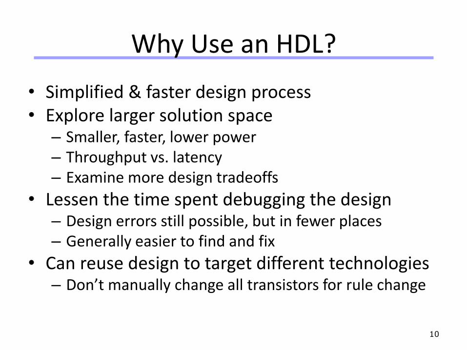
Why Use an HDL?
• Simplified & faster design process• Explore larger solution space
– Smaller, faster, lower power– Throughput vs. latency– Examine more design tradeoffs
• Lessen the time spent debugging the design– Design errors still possible, but in fewer places– Generally easier to find and fix
• Can reuse design to target different technologies– Don’t manually change all transistors for rule change
10
Universität Dortmund
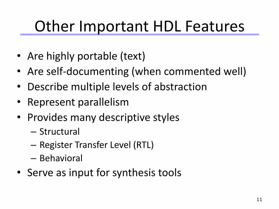
Other Important HDL Features
• Are highly portable (text)
• Are self-documenting (when commented well)
• Describe multiple levels of abstraction
• Represent parallelism
• Provides many descriptive styles– Structural
– Register Transfer Level (RTL)
– Behavioral
• Serve as input for synthesis tools
11

Universität Dortmund
HDL Overview
• HDLs may LOOK like software, but they’re not!– NOT a program
– Doesn’t “run” on anything• Though we do simulate them on computers
– This is an important distinction to remember
• Also use HDLs to test the hardware you create– Some special HDL code can be used more like
software, but is only for simulation purposes, not for synthesis
12

Universität Dortmund
HDL Dichotomy – Sim VS Synth
• HDL code can be divided into two major categories
• Synthesizable Code– Can be converted into real hardware– Bound by the same limitations as hardware– Can be both simulated and synthesized
• Non-Synthesizable Code– Only meant for simulation– Can represent behaviors that are too difficult or too
expensive to create in real hardware– Used to test the Synthesizable Code you design
13

Universität Dortmund
HDL Dichotomy – Sim VS Synth
Examples:
• Synthesizable: A 3-input AND gate
• Non-synthesizable: A 3-input AND gate that has a delay of 5 ns on Weekdays and 10 ns on Weekends
• Synthesizable: A 32-bit output bus
• Non-synthesizable: printf(“Hello World”)
14

Universität Dortmund
HDL Dichotomy – Sim VS Synth
• Unfortunately, it is not always so obvious to determine what is and isn’t synthesizable.– Some things are non-synthesizable according to the Verilog
Synthesis Standard– Some things are synthesizable only by certain synthesis
tools– Some things are synthesizable only when targeting certain
hardware
• Rely on your knowledge of hardware capabilities• This will become clearer with time & practice• Generally you can assume that we are talking about
Synthesizable code unless otherwise stated
15

Universität Dortmund
HDL Design Flow
1. Use Synthesizable code to describe the function of something that could be built in hardware
2. Use Non-Synthesizable code to create a testbench that checks to see if your Synthesizable code does what you want
3. Simulate your testbench4. Hand the Synthesizable code over to a
Synthesis Tool. The tools will convert your code to a netlist of real hardware elements (gates, cells, LUTs, etc.)
5. Simulate this netlist with your testbench and see if it still works as intended
16
RTL Coding(Verilog/VHDL)
Spec
VERIFICATION
Meets
Spec?
No
Synthesis
YesRTL

Universität Dortmund
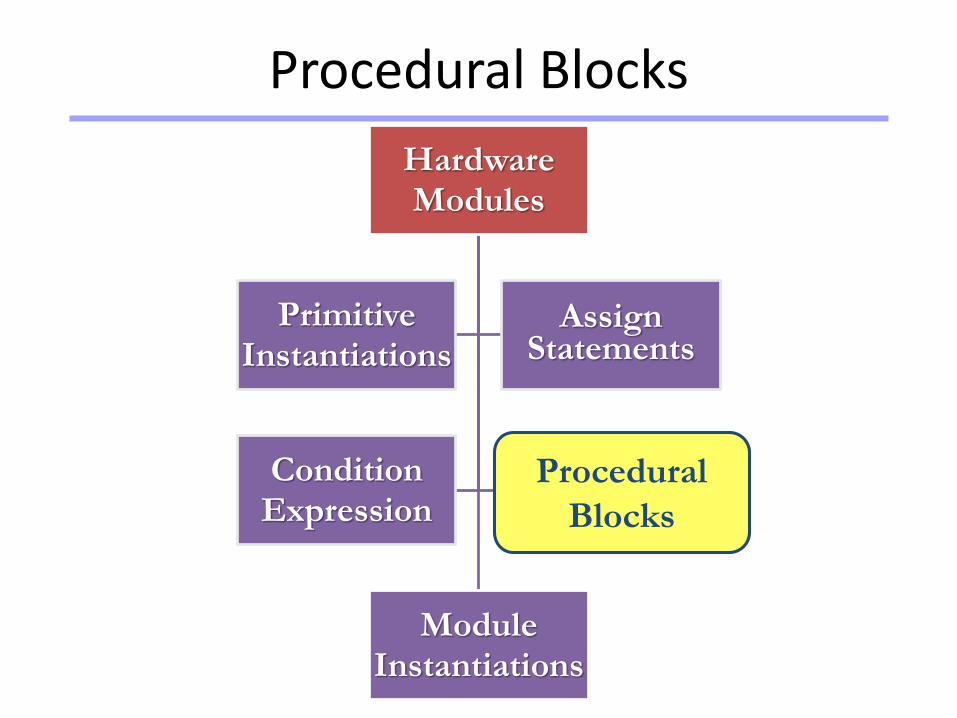
Elements of Verilog
Hardware Modules
Module Instantiations
Primitive Instantiations
Assign Statements
Condition Expression
Procedural Blocks

Universität Dortmund
Comments
• // The rest of the line is a comment
• /* Multiple line
comment */
• /* Nesting /* comments */ do NOT work */

Universität Dortmund
Verilog Value Set
• 0 represents low logic level or false condition
• 1 represents high logic level or true condition
• x represents unknown logic level
• z represents high impedance logic level

Universität Dortmund
Nets (i)
• Can be thought as hardware wires driven by logic
• Equal z when unconnected
• Various types of nets– wire
– wand (wired-AND)
– wor (wired-OR)
– tri (tri-state)

Universität Dortmund
Nets (ii)
A
BY
wire Y; // declaration
assign Y = A & B;
B
A
Y
wand Y; // declaration
assign Y = A;
assign Y = B;
wor Y; // declaration
assign Y = A;
assign Y = B;
A Y
drtri Y; // declaration
assign Y = (dr) ? A : z;

Universität Dortmund
Registers
• Variables that store values
• Do not represent real hardware but ..
• .. real hardware can be implemented with registers
• Only one type: regreg A, C; // declaration
// assignments are always done inside a procedure
A = 1;
C = A; // C gets the logical value 1
A = 0; // C is still 1
C = 0; // C is now 0
• Register values are updated explicitly!!

Universität Dortmund
Logic
• reg data type is bit mis-leading in Verilog.
• SystemVerilog's LOGIC data type addition is to remove the above confusion.
• LOGIC data type can be used to describe the unified capabilities of "reg" and "wire."

Universität Dortmund
Vectors
• Represent buseswire [3:0] busA;
reg [1:4] busB;
reg [1:0] busC;
• Left number is MS bit
• Slice managementbusC[1] = busA[2];
busC[0] = busA[1];
• Vector assignment (by position!!)busB[1] = busA[3];
busB[2] = busA[2];
busB[3] = busA[1];
busB[4] = busA[0];
busB = busA;
busC = busA[2:1];

Universität Dortmund
Arrays
• Syntaxinteger count[1:5]; // 5 integers
reg var[-15:16]; // 32 1-bit regs
reg [7:0] mem [0:1023]; // 1024 8-bit regs
• Accessing array elements– Entire element: mem[10] = 8’b 10101010;
– Element subfield (needs temp storage):reg [7:0] temp;
..
temp = mem[10];
var[6] = temp[2];

Universität Dortmund
Operators:
• Logical Operators: && || ! ……
• Reduction and Bitwise operators: & | ^ ~
• Shift and concatenation: << >> { , }
• Relational operators
• Equality operators
• Arithmetic Operators

Universität Dortmund
Hardware Modules
Hardware Modules
Module Instantiations
Primitive Instantiations
Assign Statements
Condition Expression
Procedural Blocks
Hardware
Modules

Universität Dortmund
Hardware Modules
module module-name
List of ports;
Declarations
...
Functional specification of module
...
endmodule
Module Specifications
Keyword
module
module :
The Main
Component
of Verilog
Keyword
endmodule
Variables, wires, and
module parameters
are declared.

Universität Dortmund
Hardware Modules
There is more than one way to describe a Module in Verilog.
May correspond to descriptions at various levels of abstraction or to various levels of detail of the functionality of a module.
Descriptions of the same module need not behave in exactly the same way nor is it required that all descriptions describe a behavior correctly.
We discuss basic constructs of Verilog language for a hardware module description.
We show a small example and several alternative ways to describe it in Verilog.

Universität Dortmund
Primitive Instantiations
Hardware Modules
Module Instantiations
Primitive Instantiations
Assign Statements
Condition Expression
Procedural Blocks
Primitive
Instantiations

Universität Dortmund
Primitive Instantiations
a
s
b
s_bar
a_sel
b_sel
w
A Multiplexer Using Basic Logic Gates
Logic Gates
called
Primitives

Universität Dortmund
Primitive Instantiations
module MultiplexerA (input a, b, s, output w);
wire a_sel, b_sel, s_bar;
not U1 (s_bar, s);
and U2 (a_sel, a, s_bar);
and U3 (b_sel, b, s);
or U4 (w, a_sel, b_sel);
endmodule
Primitive Instantiations
Instantiation
of Primitives

Universität Dortmund
Assign Statements
Hardware Modules
Module Instantiations
Primitive Instantiations
Assign Statements
Condition Expression
Procedural Blocks
Assign
Statements

Universität Dortmund
Assign Statements
module MultiplexerB (input a, b, s, output w);
assign w = (a & ~s) | (b & s);
endmodule
January 2006Verilog Digital System Design
Copyright Z. Navabi, 200634
Assign Statement and Boolean
Continuously
drives w with the
right hand side
expression
Using Boolean
expressions to
describe the logic

Universität Dortmund
Condition Expression
Hardware Modules
Module Instantiations
Primitive Instantiations
Assign Statements
Condition Expression
Procedural Blocks
Condition
Expression

Universität Dortmund
Condition Expression
module MultiplexerC (input a, b, s, output w);
assign w = s ? b : a;
endmodule
Assign Statement and Condition Operator
Can be used when
the operation of a
unit is too complex
to be described by
Boolean expressions
Very Effective in
describing complex
functionalities Useful in describing a
behavior in a
very compact way
Universität Dortmund
Procedural Blocks
Hardware Modules
Module Instantiations
Primitive Instantiations
Assign Statements
Condition Expression
Procedural Blocks
Procedural
Blocks
Universität Dortmund
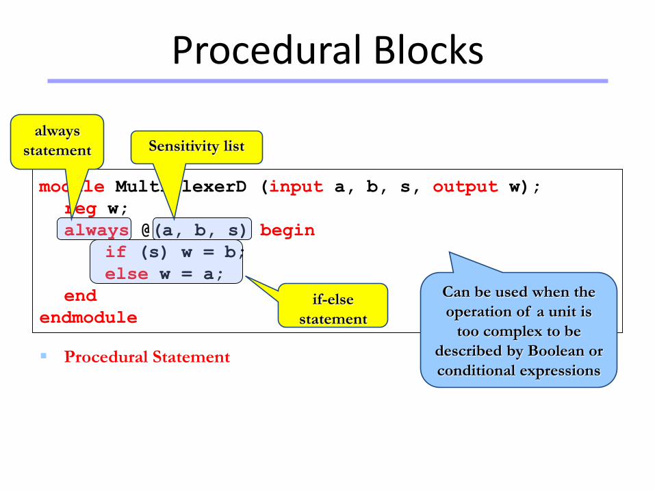
Procedural Blocks
module MultiplexerD (input a, b, s, output w);
reg w;
always @(a, b, s) begin
if (s) w = b;
else w = a;
end
endmodule
Procedural Statement
always
statement
if-else
statement
Can be used when the
operation of a unit is
too complex to be
described by Boolean or
conditional expressions
Sensitivity list
Universität Dortmund
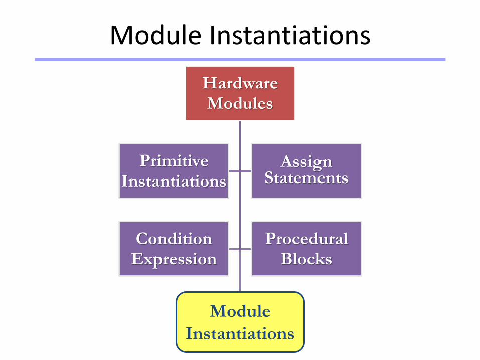
Module Instantiations
Hardware Modules
Module Instantiations
Primitive Instantiations
Assign Statements
Condition Expression
Procedural Blocks
Module
Instantiations
Universität Dortmund
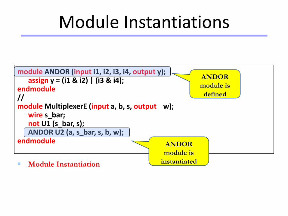
Module Instantiations
module ANDOR (input i1, i2, i3, i4, output y);assign y = (i1 & i2) | (i3 & i4);
endmodule//module MultiplexerE (input a, b, s, output w);
wire s_bar;not U1 (s_bar, s);ANDOR U2 (a, s_bar, s, b, w);
endmodule
Module Instantiation
ANDOR
module is
defined
ANDOR
module is
instantiated

Universität Dortmund
Module Instantiations
i1
i2
i3i4
y w
ANDORa
s
b
Multiplexer Using ANDOR
Universität Dortmund
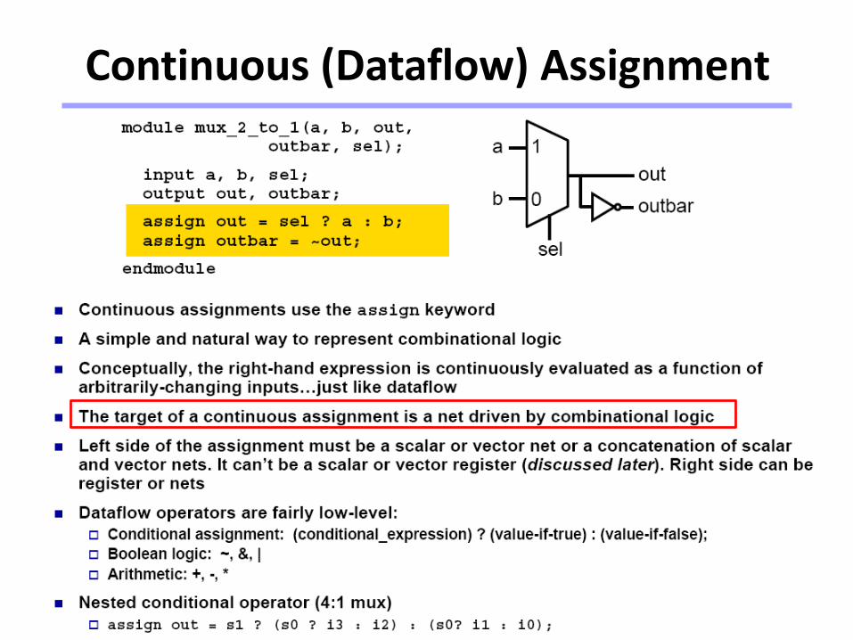
Continuous (Dataflow) Assignment

Universität Dortmund
Procedural Assignment with always

Universität Dortmund
Mix-and-Match Assignments
Universität Dortmund
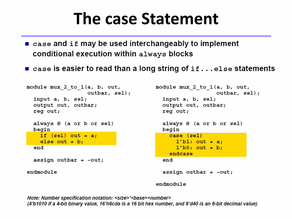
The case Statement
Universität Dortmund
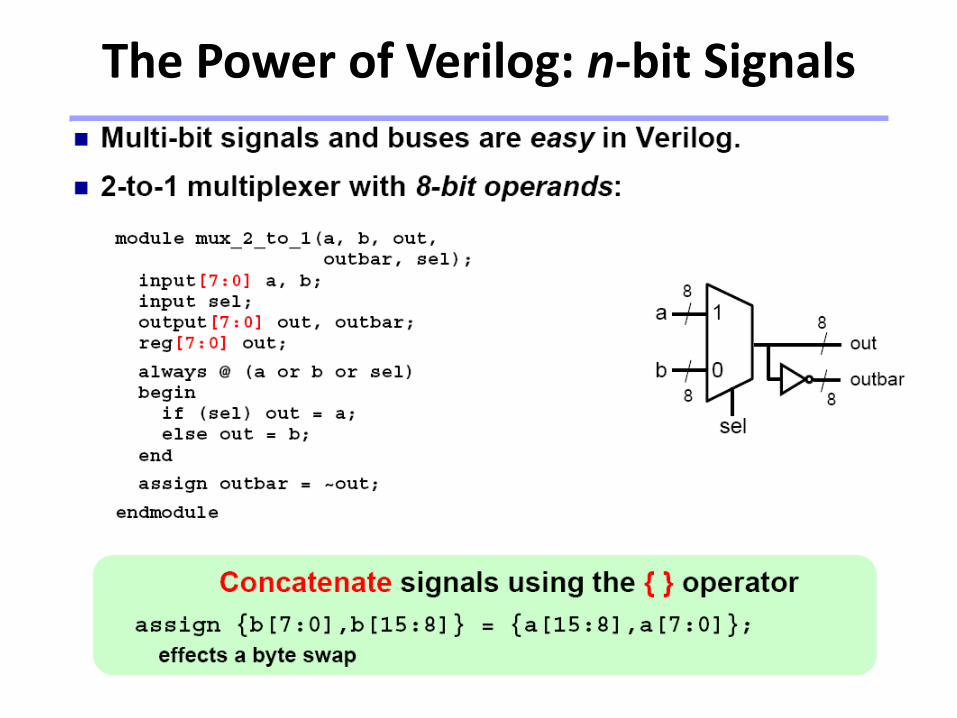
The Power of Verilog: n-bit Signals

Universität Dortmund
The Power of Verilog: Integer Arithmetic

Universität Dortmund
Dangers of Verilog: Incomplete Specification

Universität Dortmund
Incomplete Specification Infers Latches

Universität Dortmund
Avoiding Incomplete Specification

Universität Dortmund
The Sequential always Block

Universität Dortmund
Importance of the Sensitivity List

Universität Dortmund
Blocking vs. Nonblocking Assignments

Universität Dortmund
Assignment Styles for Sequential Logic

Universität Dortmund
Use Nonblocking for Sequential Logic

Universität Dortmund
Use Blocking for Combinational Logic

Universität Dortmund
Useful Boolean Operators