introduction to multilines - media.scc.losrios.edu
TRANSCRIPT

Introduction to Multilines 1
Introduction to Multilines
Engineering Design TechnologySacramento City College

Introduction to Multilines 2
Drawing MultilinesA multiline consists of between 1 and 16
parallel lines that act as one line.
The lines in the set of multilines are called elements.

Introduction to Multilines 3
Drawing MultilinesMultilines are commonly used for drawingRoadsWalls of buildings for architectural plans.

Introduction to Multilines 4
Drawing MultilinesThe MLINE command is accessed by:Picking the Multiline button from the Draw
toolbarOR
Picking Multiline in the Draw pull-down menuOR
Typing ML or MLINE at the Command: prompt.

Introduction to Multilines 5
Drawing MultilinesThree commands relate to multilines: MLINE. (ML)MLSTYLE.MLEDIT.

Introduction to Multilines 6
Drawing MultilinesThe MLSTYLE command Allows you to create multilines.

Introduction to Multilines 7
Drawing MultilinesThe default multi-line style has:Two elements (lines).Continuous line type.Is called STANDARD.

Introduction to Multilines 8
Multiline JustificationJustification determines how the resulting
lines are offset.

Introduction to Multilines 9
Multiline JustificationJustificationCan be specified only once during a single
MLINE command sequence and Is based on a counterclockwise rotation
direction.

Introduction to Multilines 10
Multiline JustificationThe justification options are TopZeroBottom
TOP is the defaultThe current value remains in effect until
changed.

Introduction to Multilines 11
Top Justification

Introduction to Multilines 12
Zero Justification

Introduction to Multilines 13
Bottom Justification

Introduction to Multilines 14
Multiline JustificationTo change the justificationEnter J at the first promptEnter the first letter of the desired justification
TopZeroBottom

Introduction to Multilines 15
Multiline JustificationThe justification setting is stored in the
AutoCAD CMLJUST system variable.

Introduction to Multilines 16
Adjusting the Multiline ScaleThe Scale option controls the multiplier for
the offset values specified in the MLSTYLEcommand.
The multiplier is stored in the CMLSCALEsystem variable.

Introduction to Multilines 17
Adjusting the Multiline ScaleWhen the scale is 1, the distance between
multiline elements is equal to 1 times the offset distance.
If the offset distance is 0.5, the distance between multiline elements is 0.5 when the multiline scale is 1.
If the multiline scale is 2, the distance between multiline elements is 1 (0.5 x 2).

Introduction to Multilines 18
Adjusting the Multiline ScaleFor zero justification, The multiline elements are offset 0.5 units on
either side of the definition points picked.
Example: If the multiline scale is 2Top and Bottom justification = 2 units offset Zero justification = 1 unit and -1 unit offset.

Introduction to Multilines 19
Setting Your Own Multiline StyleML Command Style optionAllows you to specify the current multiline
style.
The style must be saved before it can be accessed.

Introduction to Multilines 20
Setting Your Own Multiline StyleUsing saved Multiline stylesType: MLType: ST - to access the style option,
Type the known multiline style name.
A “?” lists all of the names of the multiline styles.
Typing a name of a multiline style that does not exist, the Load multiline style from file dialog box is displayed

Introduction to Multilines 21

Introduction to Multilines 22
Setting Your Own Multiline StyleMultilines are stored in the acad.mln file
library.

Introduction to Multilines 23

Introduction to Multilines 24

Introduction to Multilines 25
Setting Your Own Multiline StyleYou can load the multiline style from
another file (not acad.lin).
Custom multilines can be purchased for AutoCAD.

Introduction to Multilines 26
Defining Multilines

Introduction to Multilines 27
Multiline StylesUse the MLSTYLE command to define
multilines.

Introduction to Multilines 28
Multiline StylesThe MLSTYLE command can be accessed
by:Picking the Multiline Style entry in the Format
pull-down menuOR
Typing MLSTYLE at the Command: prompt.

Introduction to Multilines 29
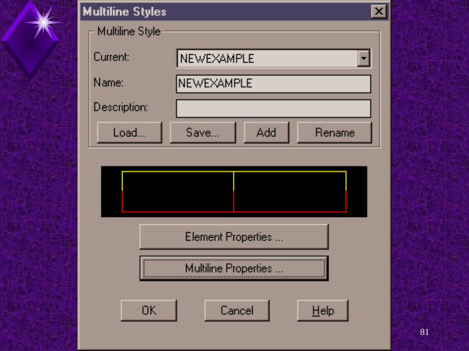
Multiline StylesThe Multiline options are:Current: Name:Description:Load... Button:Save... button.Add button. Rename button.

Introduction to Multilines 30

Introduction to Multilines 31
Multiline StylesCurrent: Text box. The Current: text box makes the specified
multiline style current. Specifying a different style changes the
setting of the CMLSTYLE system variable.
Until you create a multiline style, the only style available is STANDARD.

Introduction to Multilines 32
Multiline StylesName:Text box.This text box is used to enter the name for a
new style.
Description: Text box.An optional description of your multiline style
may be entered in this text box.

Introduction to Multilines 33

Introduction to Multilines 34
Multiline StylesLoad... button. This button allows you to load a multiline style
from an external multiline definition file.
Save... button.The Save... button is used to save a style to a
file.

Introduction to Multilines 35

Introduction to Multilines 36
Multiline StylesAdd button. Pick the Add button after entering a multiline
style name in the Name: text box. This adds the multiline style name to the list of
defined styles.
Rename button. Pick this button to rename a multiline style.

Introduction to Multilines 37

Introduction to Multilines 38
Creating A Multiline

Introduction to Multilines 39
Element Properties Dialog BoxCreate a new multiline style by1. MLStyle2. Type name of new multiline
“NewExample”3. Click ADD

Introduction to Multilines 40
Multiline Element Properties

Introduction to Multilines 41

Introduction to Multilines 42
Element Properties Dialog BoxElements Properties Dialog Box contains:Elements: area. Add button.Delete button. Offset text box. Color... button.Linetype... button.

Introduction to Multilines 43
Element Properties Dialog BoxElements: area. Displays the current:
Offset.ColorLinetype settings
for each multiline element.
Picking one of the elements highlights the items for modification.

Introduction to Multilines 44

Introduction to Multilines 45
Element Properties Dialog BoxAdd button. Add a new element to the multiline definition.
Delete button. Deletes a highlighted item in the Elements:
area.

Introduction to Multilines 46

Introduction to Multilines 47

Introduction to Multilines 48
Element Properties Dialog BoxOffset text box. Enter either a positive or negative offset value
for a highlighted element.

Introduction to Multilines 49

Introduction to Multilines 50
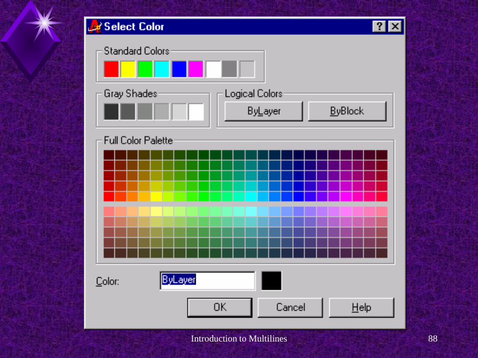
Element Properties Dialog BoxColor... button.Accesses the Select Color dialog box.Pick the color you wish to assign to the
highlighted element. After picking OK, the new color is displayed in
the image tile next to the Color... button.

Introduction to Multilines 51

Introduction to Multilines 52

Introduction to Multilines 53
Element Properties Dialog BoxLinetype... button. Pick the desired linetype from the Loaded
Linetypes list.
Linetypes must be loaded before they can be used.

Introduction to Multilines 54

Introduction to Multilines 55

Introduction to Multilines 56

Introduction to Multilines 57

Introduction to Multilines 58

Introduction to Multilines 59

Introduction to Multilines 60

Introduction to Multilines 61
Multiline Properties Options

Introduction to Multilines 62
Multiline Properties Dialog Box The Multiline Properties dialog box offers
additional options for customizing multiline styles.
Access by:Picking the Multiline Properties... button in the
Multiline Styles dialog box. See Figure 15-12.

Introduction to Multilines 63

Introduction to Multilines 64

Introduction to Multilines 65
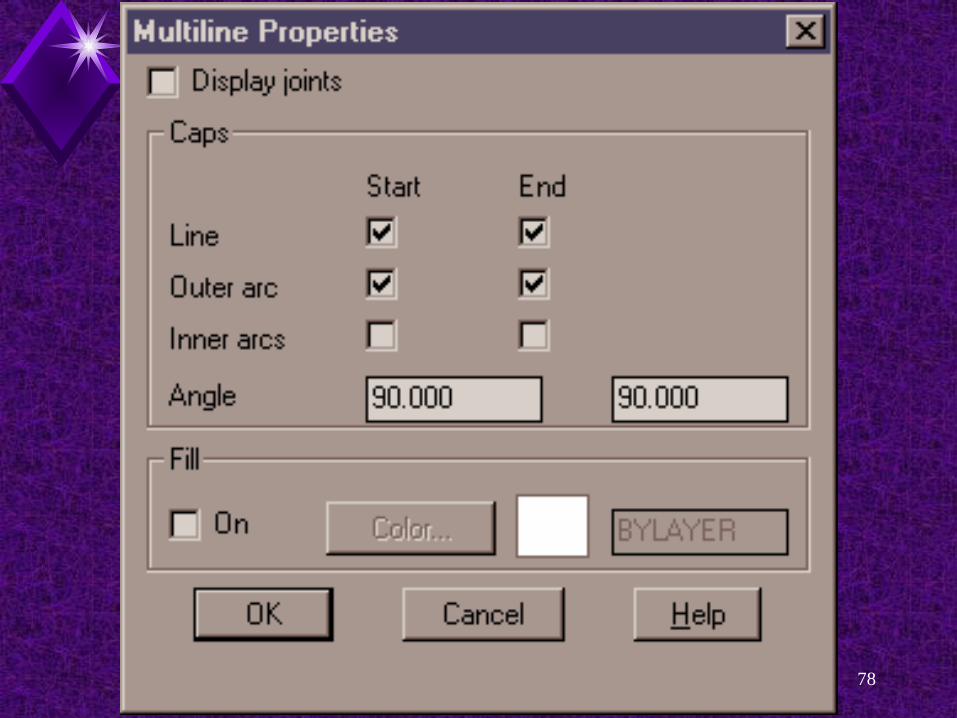
Multiline Properties Dialog Box You can add the following to multi-line
elementsCaps.Segment joints.Background color.

Introduction to Multilines 66
Multiline Properties Dialog Box JointsAre lines that connect the vertices of adjacent multiline
elements. Joints are also called miters.
Display joints check box. This check box turns the display of joints on
and off.

Introduction to Multilines 67

Introduction to Multilines 68

Introduction to Multilines 69
Multiline Properties Dialog BoxCapsAre lines that Connect the vertices of the beginning or
ending points of the multiline elements.
Caps area. Controls the placement of caps on multilines.

Introduction to Multilines 70

Introduction to Multilines 71

Introduction to Multilines 72

Introduction to Multilines 73

Introduction to Multilines 74
Multiline Properties Dialog BoxCaps can be set at the Start pointsEndpointsBoth.

Introduction to Multilines 75
Multiline Properties Dialog BoxArcs can also be specified. Arcs can be set to connect the Ends of the outermost elements onlyPairs of interior elementsBoth the outer and interior elements. The arcs are drawn tangent to the elements
they connect.Specifying outermost arcs to be drawn
requires at least two multiline elements.

Introduction to Multilines 76

Introduction to Multilines 77
Introduction to Multilines 78

Introduction to Multilines 79

Introduction to Multilines 80
Introduction to Multilines 81

Introduction to Multilines 82
Introduction to Multilines 83
Multiline Properties Dialog BoxAngle: Text BoxAllows you to change the angle of the caps
relative to the direction of the multiline elements.

Introduction to Multilines 84

Introduction to Multilines 85

Introduction to Multilines 86
Multiline Properties Dialog BoxFill area. If the check box labeled On is activated, the
multiline is filled with a solid fill pattern in the color specified.
Pick this check box to activate the Color... button.
You can leave the color set to BYLAYER or change it by picking the Color... button.

Introduction to Multilines 87
Introduction to Multilines 88
Introduction to Multilines 89

Introduction to Multilines 90

Introduction to Multilines 91
Multiline Styles
Introduction to Multilines 92
Multiline StylesMLSTYLE command Displays the Multiline Styles dialog box.Use this box to define, edit, and save multiline
styles.
Styles can be saved to an external file so they can be used in other drawings.

Introduction to Multilines 93

Introduction to Multilines 94
Editing Multilines

Introduction to Multilines 95
Editing MultilinesThe MLEDIT command permits limited
editing operations for multiline objects.

Introduction to Multilines 96
Editing MultilinesAccess this command byPicking Multiline... from the Modify pull-down
menuOR
Entering MLEDIT at the Command: promptOR
Picking the Edit Multiline button in the Modify toolbar.

Introduction to Multilines 97
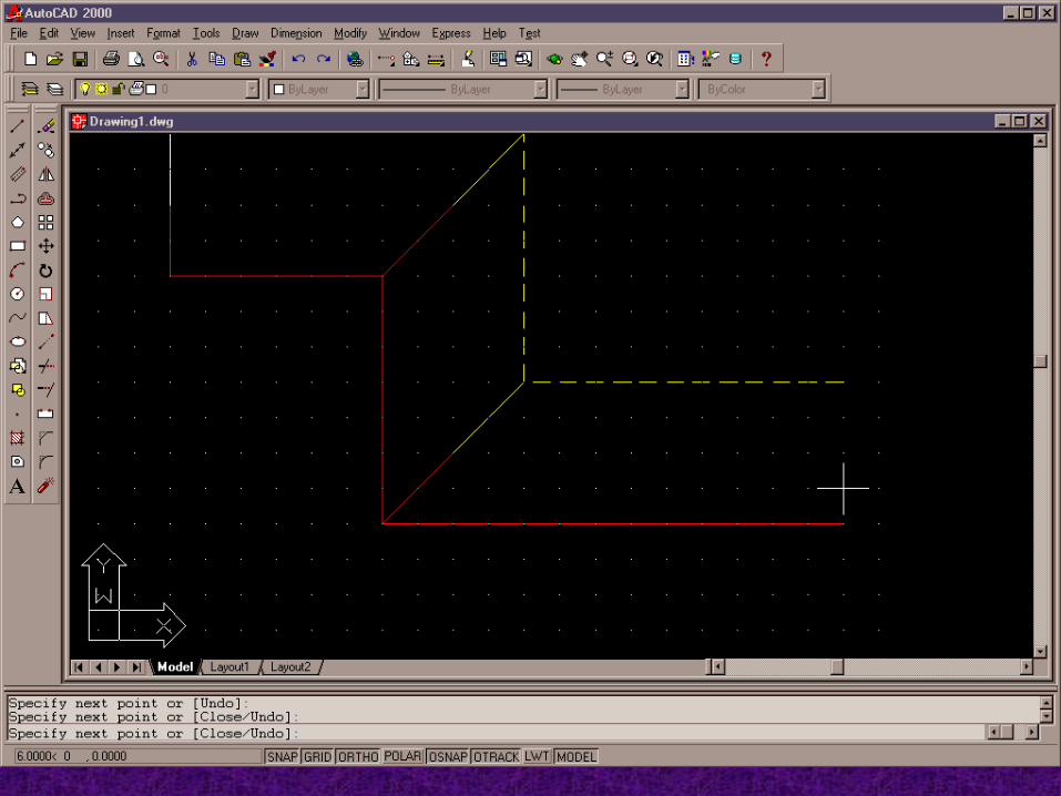
Editing MultilinesThe Multiline Edit Tools dialog box is
displayed.

Introduction to Multilines 98
Editing MultilinesThe image buttons give you an example of
what to expect when using each editing option.

Introduction to Multilines 99

Introduction to Multilines 100
Editing IntersectionsPick a button to create the type of
intersection shown.
The name of the MLEDIT option is displayed in the lower left comer of the dialog box when you pick an image button.

Introduction to Multilines 101
Editing IntersectionsClosed Cross.The first multiline selected is called the
background. It remains unchanged.The second multiline selected is called the
foreground. It remains unchanged.

Introduction to Multilines 102
Editing IntersectionsNote that the trimming is apparent, not
actual. ( ! )
This means that the line visibility of the background multiline is changed, but it is still one multiline.

Introduction to Multilines 103

Introduction to Multilines 104
Editing IntersectionsU to undo the intersection you have just
made.

Introduction to Multilines 105
Editing IntersectionsCross editing options:Closed Cross.Open Cross.Merged Cross.

Introduction to Multilines 106

Introduction to Multilines 107
Editing TeesOther Tee editing options:Closed TeeOpen Tee.Merged Tee.

Introduction to Multilines 108

Introduction to Multilines 109
Editing IntersectionsOther options:Corner Joint.Add Vertex.Delete Vertex.
Cut Single.Cut All.Weld All.

Introduction to Multilines 110

Introduction to Multilines 111
Editing IntersectionsCorner Joint. Allows you to create a corner joint between
two multilines. The first multiline is trimmed or extended to its
intersection with the second multiline.

Introduction to Multilines 112

Introduction to Multilines 113
Editing IntersectionsAdd Vertex. Adds a vertex to an existing multiline at the
location you pick.

Introduction to Multilines 114
Editing IntersectionsAdd VertexThe command sequence differs slightly from
the sequences used with the other MLEDIT options.
After you select the Add Vertex option and pick OK, you are prompted with the following:
Select mline: (pick a location on the multilinefor the new vertex)
Select mline or [Undo]: jCommand:

Introduction to Multilines 115
Editing IntersectionsDelete Vertex. The Delete Vertex option allows you to
remove a vertex from an existing multiline.The vertex closest to the location you pick is
deleted.

Introduction to Multilines 116