introduction to network room module (nrm) - johnson...
TRANSCRIPT

Technical Bulletin Network Room Module Issue Date January 22, 2010
© 2010 Johnson Controls, Inc. Code No. LIT-12011258
Network Room Module
Introduction to Network Room Module (NRM)..................................... 3
Concepts .............................................................................................................. 4
Features ............................................................................................................................. 4
Controls.............................................................................................................................. 5
Functions and Setup of the Network Room Module........................................................... 6
Network Room Module Parameters (Room Sensor Object) ............................................ 13
Installing and Commissioning the Network Room Module .............. 15
Introduction........................................................................................................ 15
North American Emissions Compliance........................................................................... 15
Key Concepts..................................................................................................... 16
Location of the Network Room Module ............................................................................ 16
Dimensions of the Network Room Module....................................................................... 17
Wiring ............................................................................................................................... 18
Addressing ....................................................................................................................... 19
Service Port...................................................................................................................... 20
Commissioning the Network Room Module ..................................................................... 22
Procedure Overview......................................................................................................... 23
Detailed Procedures.......................................................................................... 23
Opening the Network Room Module ................................................................................ 23
Mounting the NRM Directly on a Wall Surface................................................................. 24
Mounting the NRM (80 x 80 mm) on a Wall Surface Using the Plastic Base for Surface Mounting ................................................................................... 26
Mounting the NRM (80 x 80 mm) on a Recessed Wall Box............................................. 27
Commissioning the NRM Module..................................................................................... 29

Network Room Module Technical Bulletin 2
Troubleshooting ................................................................................... 30
Specifications and Ordering Codes.................................................... 31
Specifications and Technical Data................................................................... 31
Ordering Codes ................................................................................................. 32

Network Room Module Technical Bulletin 3
Introduction to Network Room Module (NRM)
Network Room Modules (NRMs) are electronic, wall-mountable temperature sensors designed to be used with the Facility Explorer field controllers.
Note: See the Specifications and Ordering Codes section for details about compatible controllers.
All NRM models monitor room or space temperature. In addition, you can order NRMs with a backlit Liquid Crystal Display (LCD) to display the room temperature and local setpoint. Graphical display symbols can indicate fan speed selection and the need for maintenance. Optional operating controls include a dial to locally adjust the space temperature setpoint, a push button to manually override the fan speed, and a push button to select Fahrenheit (°F) and Celsius (°C) units of measure.
The NRM connects to the Remote Display link of the Facility Explorer field controller. Terminals are located in the mounting base for ease of wiring. The NRM is enclosed in an attractively styled plastic housing, which easily mounts on a wall.
Figure 1: Network Room Modules
Network Room Module Technical Bulletin 4
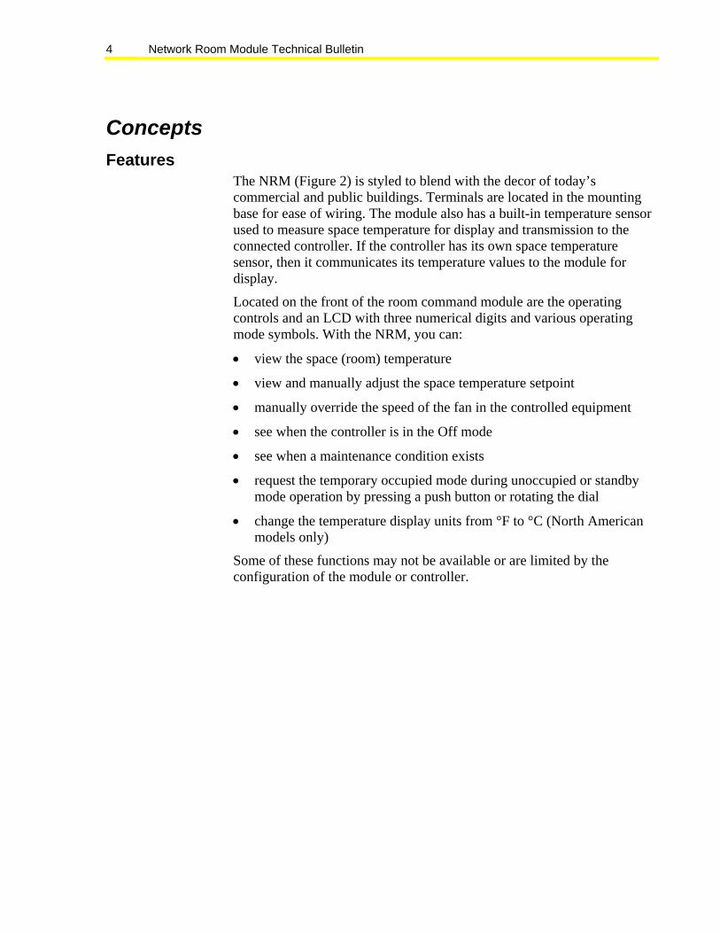
Concepts Features
The NRM (Figure 2) is styled to blend with the decor of today’s commercial and public buildings. Terminals are located in the mounting base for ease of wiring. The module also has a built-in temperature sensor used to measure space temperature for display and transmission to the connected controller. If the controller has its own space temperature sensor, then it communicates its temperature values to the module for display.
Located on the front of the room command module are the operating controls and an LCD with three numerical digits and various operating mode symbols. With the NRM, you can:
• view the space (room) temperature
• view and manually adjust the space temperature setpoint
• manually override the speed of the fan in the controlled equipment
• see when the controller is in the Off mode
• see when a maintenance condition exists
• request the temporary occupied mode during unoccupied or standby mode operation by pressing a push button or rotating the dial
• change the temperature display units from °F to °C (North American models only)
Some of these functions may not be available or are limited by the configuration of the module or controller.

Network Room Module Technical Bulletin 5
The NRM has a service port (located on the lower edge of the module). Use the service port to gain access to the serial bus for the host FX field controller. Two types of service ports are available (see Figure 2 for service port location).
• The service port for NRM model LP-NRM0xx-000C is a 4-pin connector and is used to interface with the FX Programming Key.
• The service port for NRM models LP-NRM5xx-000C and LP-NRM6xx-000C is a 6-pin Modular Jack connector and is used to interface with the Medium User Interface (MUI).
Figure 2: Features of the Network Room Module
Controls Table 1 shows how the dial and buttons are used in the NRM.
Table 1: Controls Control Description
Setpoint Dial
Used to change the temperature setpoint value: turning right increases the setpoint and turning left decreases the setpoint. When you move the dial, the display shows the current space temperature setpoint.
Fan Push Button
Used to override the fan status from Auto to Off, low, medium, or high speed.
°F/°C
°F/°C Push Button
Used to toggle the temperature display units between °C and °F.
Network Room Module Technical Bulletin 6
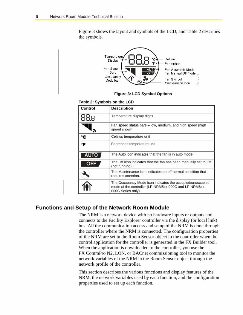
Figure 3 shows the layout and symbols of the LCD, and Table 2 describes the symbols.
Figure 3: LCD Symbol Options
Table 2: Symbols on the LCD Control Description
Temperature display digits
Fan speed status bars – low, medium, and high speed (high speed shown)
°C Celsius temperature unit
°F Fahrenheit temperature unit
AUTO The Auto icon indicates that the fan is in auto mode.
OFF The Off icon indicates that the fan has been manually set to Off (not running).
The Maintenance icon indicates an off-normal condition that requires attention.
The Occupancy Mode icon indicates the occupied/unoccupied mode of the controller (LP-NRM5xx-000C and LP-NRM6xx-000C Series only).
Functions and Setup of the Network Room Module The NRM is a network device with no hardware inputs or outputs and connects to the Facility Explorer controller via the display (or local link) bus. All the communication access and setup of the NRM is done through the controller where the NRM is connected. The configuration properties of the NRM are set in the Room Sensor object in the controller when the control application for the controller is generated in the FX Builder tool. When the application is downloaded to the controller, you use the FX CommPro N2, LON, or BACnet commissioning tool to monitor the network variables of the NRM in the Room Sensor object through the network profile of the controller.
This section describes the various functions and display features of the NRM, the network variables used by each function, and the configuration properties used to set up each function.

Network Room Module Technical Bulletin 7
See Network Room Module Parameters (Room Sensor Object) for a detailed list of the variables and properties of the NRM. The names of the network variables and configuration properties appear in boldface type throughout this document.
Note: After a power failure, the NRM restarts using the values in its configuration properties and any setpoint changes or fan speed overrides are cancelled. In particular, if you set the Setpoint Configuration to absolute, you should also set the Default Absolute Setpoint for the controlled space in case of a power interruption. The factory set value is 21°C (70°F).
Display The NRM models with display are factory-configured to show space temperature. The models with the fan speed override function are configured for three-speed fan control. As soon as you connect the NRM to a controller with a configured Room Sensor object, the properties in the Room Sensor object transmit to the NRM and replace the factory set values.
You can change the setpoint temperature by rotating the dial. The space setpoint value appears and blinks for a few seconds, waiting for a change. The NRM then confirms the change to the controller and displays the space temperature again (if enabled).
In models with the fan speed override function, you can change the fan speed by pressing the fan push button. The fan status display cycles through the steps AUTO, OFF, Low Speed, Medium Speed, and High Speed, according to the fan configuration.
If you set the Enable Space Temperature Display configuration property to disabled (OFF), the NRM always shows the space setpoint temperature and does not show the actual space temperature.
Note: The network variable output Space Temperature Output always sends its internal space temperature value, even if the space temperature does not appear.
Depending on the values of the Setpoint Configuration and Temperature Units configuration properties, the display shows either the absolute setpoint or the setpoint offset. The absolute setpoint is stored in the Setpoint Output (Absolute) network variable output. The setpoint offset is stored in the Setpoint Output (Offset) network variable output. Some space setpoint temperature display examples are shown in Figure 4 and Figure 5.

Network Room Module Technical Bulletin 8
Figure 4: Absolute Setpoint Values in Celsius and Fahrenheit Units
Figure 5: Relative (Offset) Setpoint Values in Celsius Units
Setpoint Adjustment You can change the value of the setpoint by rotating the NRM dial to the right to increase the setpoint, and to the left to decrease the setpoint. The display stops at the high and low limits. The high and low limits are:
• ±3°C (±5°F) - if the NRM is configured to display the setpoint offset, or
• the values are defined in the Space Temperature Setpoint Low Limit and Space Temperature Setpoint High Limit configuration properties, if the NRM is configured to display the absolute setpoint. The default absolute setpoint limits are 12 and 28°C (53.5 and 82.5°F).
When you adjust the setpoint, the value you enter is transmitted to the controller via either the network variable output Setpoint Output (Absolute) or Setpoint Output (Offset), depending on the value of Setpoint Configuration. The network variable that is not used is set to an invalid value.
The Setpoint Output (Absolute) value when the NRM starts up is determined by the Default Absolute Setpoint value in the Room Sensor object in the controller. The factory set value is 21°C (70°F). The Setpoint Output (Offset) value is zero at startup.
Fan Speed Adjustment In NRM models with the fan speed override function, you can change the speed of the fan by pressing the fan push button until the desired speed appears on the fan speed bars. See Figure 6. The override value then transmits to the controller via the network variable output Fan Speed Override. When the fan is set to Off mode by an override command, the OFF symbol appears.

Network Room Module Technical Bulletin 9
When the fan is set to Auto mode, the Auto symbol appears, and the controller determines the fan speed using its internal control algorithm.
Figure 6: Fan Speed Display in Manual Override The fan symbol ( ) is always shown, whether the fan is running or not. Examples of the fan speed display are shown in Table 3.
Table 3: Examples of Fan Speed Display Control Description
Fan speed was overridden to medium speed by the user.
Fan speed is overridden to OFF by the user.
Fan in AUTO mode – no override by user. The actual fan speed is not shown.
The type of fan is configurable in the property Fan Configuration for:
• None (no fan)
There is no fan. The fan override function is disabled (Figure 7).
Figure 7: No Fan Display
• One speed
If you set the property to One speed fan, pressing the fan push button cycles the fan status: AUTO, OFF, and ON. The display fills all three fan bars to indicate the ON status.
• Two speed
If you set the property to Two speed fan, pressing the fan push button cycles the fan status: AUTO, OFF, low, and high speed. The display shows two fan bars for low speed and three bars for high speed.

Network Room Module Technical Bulletin 10
• Three speed
If you set the property to Three speed fan, pressing the fan push button cycles the fan status: AUTO, OFF, low, medium, and high speed.
Occupancy Mode The LED display indicates the Effective Occupancy Status when the Enable Unoccupied State Blink configuration property is set to enabled (ON) and the network variable input Effective Occupancy Status value shows that the occupancy mode is UNOCCUPIED or STANDBY. See Figure 8 and Table 4.
Figure 8: Occupancy Mode Icon for LP-NRM5xx-000C and LP-NRM6xx-000C Series NRMs
Table 4: Effective Occupancy Status NRM Series Effective
Occupancy Status
Icon/Description
Occupied The display remains on. LP-NRM0xx-000C Series Unoccupied or Standby
The display blinks off/on approximately every 3 seconds.
Occupied
LP-NRM5xx-000C and LP-NRM6xx-000C Series
Unoccupied or Standby
This feature indicates to the unexpected occupant (or an occupant present during nonstandard hours) that the controller is not in the OCCUPIED mode. You can disable this feature by setting the Enable Unoccupied State Blink configuration property to disabled (OFF).

Network Room Module Technical Bulletin 11
Temporary Occupied Mode The Temporary Occupancy Mode Request output network variable normally reflects the value of the Effective Occupancy Status input network variable as received from the controller. In UNOCCUPIED or STANDBY mode, you can force the Temporary Occupancy Mode Request output variable to Temporary Occupied (BYPASS) mode for the time duration (in minutes) set in the configuration property Temporary Occupied Time. You achieve this Temporary Occupied mode when you press the fan push button or rotate the setpoint dial. The BYPASS state of the Temporary Occupancy Mode Request network variable is then transmitted to the connected controller to set the occupancy status of the controller to the Temporary Occupied (BYPASS) mode. When the temporary occupied time expires, the value of Temporary Occupancy Mode Request returns to the value of the Effective Occupancy Status input variable. This operation depends on the correct configuration of the application in the controller using FX Builder.
Off Mode When the network variable input HVAC Application Mode has the OFF (state 6) value, the display shows OFF in the upper display field to indicate that no control action is possible.
Figure 9: OFF Mode Display (HVAC Application Mode)
Maintenance Icon The maintenance icon ( ) appears on the display when the configuration property Enable Maintenance Icon is enabled (ON) and one of the following conditions exists:
• The network variable input Display Maintenance Icon is ON. The control application in the controller determines the conditions for the network variable to be on.
• The internal space temperature value, as seen in Space Temperature Output, is unreliable (out of range).
• There is no communication with an FX controller.
You can choose not to display the maintenance icon on the NRM by setting the configuration property Enable Maintenance Icon to disabled (OFF).

Network Room Module Technical Bulletin 12
Back Light Time-out The LCD is back-lit in the NRM and lights up when the fan or °F/°C push button is pressed or the dial is turned. The back-light time-out is set in the Back-light Time-out configuration property. The factory default setting is 30 seconds. A value of 0 disables the back-light; a value greater than 60 keeps the back-light permanently on.
Temperature Units on Display In NRM models without the °F/°C push button, the temperature units on the display are determined by the Temperature Units configuration property.
In NRM models with the °F/°C push button, the Temperature Units configuration property determines the temperature units on the display at start-up, but the units are toggled between °F and °C by pressing the push button.
Physical Address The NRM has a physical address that you must set in the PhysicalAddress configuration property in the Room Sensor object of the FX controller.
Non-addressable NRM models have a fixed address of 191, which is the default setting of the Room Sensor object. Addressable NRM models include DIP switches, allowing you to set the physical address between 191 and 194.
Note: You must cycle power to the NRM (disconnect/reconnect the NRM or cycle power to the field controller) for the address change to take effect.
Network Room Module Technical Bulletin 13
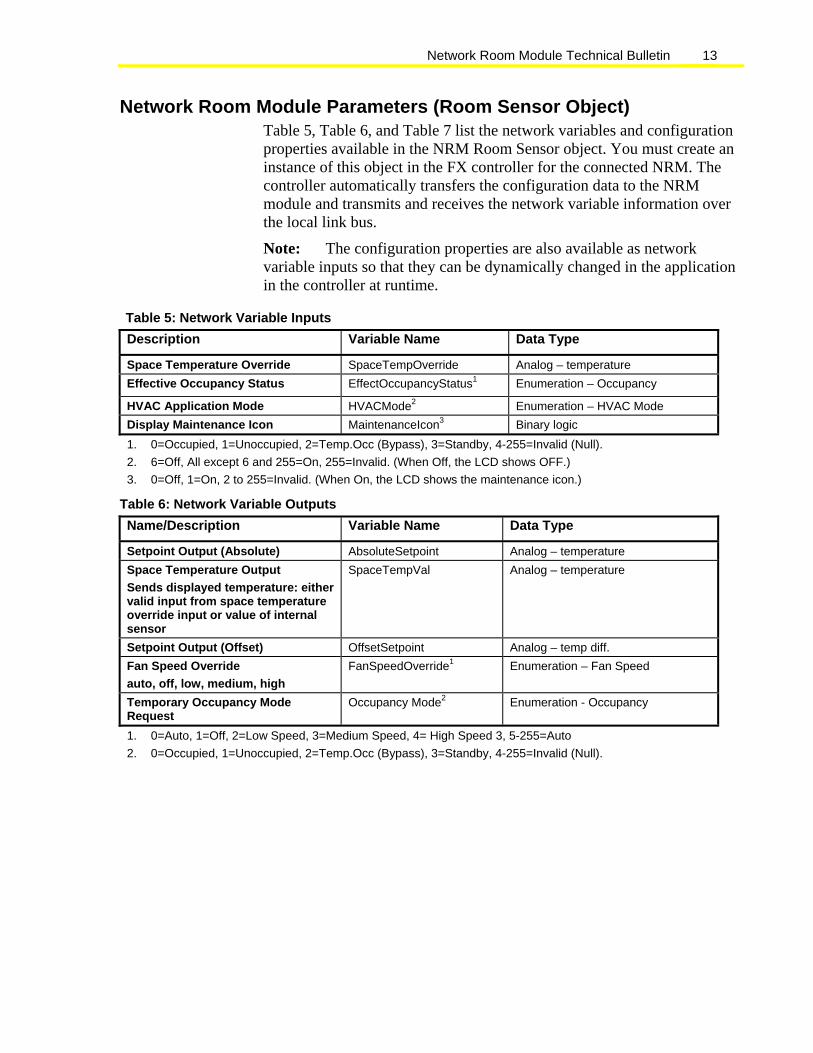
Network Room Module Parameters (Room Sensor Object) Table 5, Table 6, and Table 7 list the network variables and configuration properties available in the NRM Room Sensor object. You must create an instance of this object in the FX controller for the connected NRM. The controller automatically transfers the configuration data to the NRM module and transmits and receives the network variable information over the local link bus.
Note: The configuration properties are also available as network variable inputs so that they can be dynamically changed in the application in the controller at runtime.
Table 5: Network Variable Inputs Description Variable Name Data Type
Space Temperature Override SpaceTempOverride Analog – temperature Effective Occupancy Status EffectOccupancyStatus1 Enumeration – Occupancy
HVAC Application Mode HVACMode2 Enumeration – HVAC Mode Display Maintenance Icon MaintenanceIcon3 Binary logic 1. 0=Occupied, 1=Unoccupied, 2=Temp.Occ (Bypass), 3=Standby, 4-255=Invalid (Null). 2. 6=Off, All except 6 and 255=On, 255=Invalid. (When Off, the LCD shows OFF.) 3. 0=Off, 1=On, 2 to 255=Invalid. (When On, the LCD shows the maintenance icon.)
Table 6: Network Variable Outputs Name/Description Variable Name Data Type
Setpoint Output (Absolute) AbsoluteSetpoint Analog – temperature Space Temperature Output Sends displayed temperature: either valid input from space temperature override input or value of internal sensor
SpaceTempVal Analog – temperature
Setpoint Output (Offset) OffsetSetpoint Analog – temp diff. Fan Speed Override auto, off, low, medium, high
FanSpeedOverride1 Enumeration – Fan Speed
Temporary Occupancy Mode Request
Occupancy Mode2 Enumeration - Occupancy
1. 0=Auto, 1=Off, 2=Low Speed, 3=Medium Speed, 4= High Speed 3, 5-255=Auto 2. 0=Occupied, 1=Unoccupied, 2=Temp.Occ (Bypass), 3=Standby, 4-255=Invalid (Null).

Network Room Module Technical Bulletin 14
Table 7: Configuration Properties Name/Description Property Name Data Type Default Limits
Space Temperature Setpoint High Limit
SpaceTempSetptHighLimit Analog - Temperature
28.0°C (82.5°F) Max. 40°C (99.5°F)
Space Temperature Setpoint Low Limit
SpaceTempSetptLowLimit Analog - Temperature
12.0°C (53.5°F) Min. 0°C (32.0°F)
Temporary Occupied Time
TemporaryOccupiedTime Analog - minutes 60 min 0 to 255 min
Fan Configuration FanConfiguration1 Enumeration – fan speed
Three speed 0, 1, 2, 3
Setpoint Configuration
(absolute or offset)
SetpointConfig2 Binary logic 0 = Absolute Absolute or Offset
Temperature Units (display units °C or °F)
TemperatureUnits3 Binary logic 0 = SI (°C) SI or US
Enable Space Temperature Display (defines if space temperature is shown)
EnableSpaceTempDisplay Binary logic ON=Enabled OFF or ON
Default Absolute Setpoint
DefaultAbsoluteSetpt Analog - temperature
21°C (70°F) 0 to 40°C (32 – 99.5°F)
Back-light Time-out BackLightTime4 Analog - seconds 30 sec 0 to 60 seconds
Temperature Sensor Offset
TemperatureOffset Analog – temp. diff.
0°C ±5°C (±9°F)
Enable Unoccupied State Blink
EnableUnoccupiedBlinking Binary logic ON=Enabled OFF or ON
Enable Maintenance Icon
EnableMaintDispIcon Binary logic ON=Enabled OFF or ON
Physical Address PhysicalAddress Integer 191 191 to 194
1. 0=None, 1=One speed fan, 2=Two speed fan, 3=Three speed fan 2. 0=Absolute Setpoint, 1=Offset Setpoint (±3°C) (±5°F) 3. 0=SI (°C), 1=US (°F) 4. 0=No back-light, >60=Back-light always on

Network Room Module Technical Bulletin 15
Installing and Commissioning the Network Room Module
Introduction The Network Room Module is designed to mount directly on a wall surface in the room you want to control. Separate kits are also available for wall surface mounting with conduits and recessed wall box mounting (see Ordering Codes). The wiring enters the module from the back.
IMPORTANT: Use this Network Room Module only as an operating control. Where failure or malfunction of the NRM could lead to personal injury or property damage to the controlled equipment or other property, additional precautions must be designed into the control system. Incorporate and maintain other devices, such as supervisory or alarm systems or safety or limit controls, intended to warn of or protect against failure or malfunction of the NRM.
North American Emissions Compliance United States This equipment has been tested and found to comply with the limits for a Class A digital device pursuant to Part 15 of the FCC Rules. These limits are designed to provide reasonable protection against harmful interference when this equipment is operated in a commercial environment. This equipment generates, uses, and can radiate radio frequency energy, and if not installed and used in accordance with the instruction manual, may cause harmful interference to radio communications. Operation of this equipment in a residential area is likely to cause harmful interference, in which case the user will be required to correct the interference at his/her own expense.
Canada This Class (A) digital apparatus meets all the requirements of the Canadian Interference-Causing Equipment Regulations.
Cet appareil numérique de la Classe (A) respecte toutes les exigences du Règlement sur le matériel brouilleur du Canada.

Network Room Module Technical Bulletin 16
Key Concepts Location of the Network Room Module
Choose a location for the NRM, taking the following information into consideration:
• Place the NRM where the occupant can easily read the LCD and use the controls.
• Place the NRM where the ambient temperature is representative of the general room conditions if you want to use the built-in temperature sensor to measure space temperature. For example, there should be sufficient air circulation.
• Avoid cold or warm air drafts, radiant heat, and direct sunlight.
• Place some insulating material in the wiring access hole or conduit to prevent the introduction of air from outside the room.
IMPORTANT: The installation of electrical wiring must conform to local codes and should be carried out by authorized personnel only. Users should ensure that all Johnson Controls® products are used safely and without risk to health or property.

Network Room Module Technical Bulletin 17
Dimensions of the Network Room Module
Figure 10: Network Room Module Dimensions, mm (in.)

Network Room Module Technical Bulletin 18
Wiring Terminations are made on the terminal block in the base of the module, which is accessible after removing the cover from the base. The screw terminals accept up to 1.5 mm2 (16 AWG) wires, and Figure 11 shows the terminal block connections. Complete and verify all wiring connections before you apply power to the module.
12 13 14 11
POWER SUPPLYINPUT
N2 RT+COM
N2 RT-
Figure 11: Wiring to the NRM Follow this information when you wire an FX controller to an NRM:
! CAUTION: Risk of Electric Shock. Disconnect power supply before making electrical connections to avoid electric shock.
IMPORTANT: The LP-NRM0xx-000C Series NRM accepts VAC or VDC power. The LP-NRM5xx-000C and LP-NRM6xx-000C Series accept VDC power only.
• Connect power to terminals 11 (+ VDC or VAC) and 14 (- VDC or VAC). You may take power from the FX controller (15 VDC).
Note: The COM terminal of the NRM is connected to the common potential of the FX controller. If an independent power supply is used for the NRM, ensure the proper connection of the multiple power supplies to avoid a short circuit through the NRM module or FX controller.
• Use screw terminals 12 (N2 RT+), 13 (N2 RT-) and 14 (COM) to connect to the FX controller display (local ink) bus terminals (LL+, LL-, and COM, respectively). This is an RS-485 bus where the wires are polarity sensitive. A common or reference wire is required and the N2 Open protocol is used. All the installation rules for the N2 bus apply to this connection.
• If shielded cable is used for the network wiring, connect the shields together and insulate with tape. Do not use the COM terminal for cable shields.

Network Room Module Technical Bulletin 19
Note: The device does not require a ground/earth connection.
IMPORTANT: Cables and wiring at Safety Extra Low Voltage (SELV) and Class 2 wiring (North America) must be separated from power line voltage wiring. A minimum separation distance of 30 cm (12 in.) is recommended. Do not run extra low voltage cables parallel to power line voltage cables for long distances greater than 3 m (10 ft). Do not run extra low voltage wiring close to transformers or high frequency generating equipment.
Addressing Non-addressable NRM models have a fixed physical address of 191. For those models which are addressable, the NRM’s address must be set using its dual-switch DIP switch block, located on the printed wiring board. See Figure 12 and Table 8 for details on addressing the NRM.
Note: You must cycle power to the NRM (disconnect/reconnect the NRM or cycle power to the field controller) for the address change to take effect.
Figure 12: Dual-Switch DIP Switch Block
Table 8: NRM Addressing DIP Switch Address Switch 2 Switch 1
191 OFF OFF 192 OFF ON
193 ON OFF 194 ON ON

Network Room Module Technical Bulletin 20
Service Port The NRM features a service port which is located on the bottom-right side of the module (Figure 13 and Figure 15). Two types of service ports are supported, depending on the NRM model number.
The service port for NRM model LP-NRM0xx-000C is a 4-pin connector and is used for the connection of the FX Programming Key (Figure 14) to download applications to the connected FX field controller over the local link bus. The connector provides access to the local link bus and a power supply of 9 VDC for the Programming Key.
Figure 13: LP-NRM0xx-000C Series Service Tool Socket (4-pin Connector)
Figure 14: FX Programming Key

Network Room Module Technical Bulletin 21
The service port for NRM models LP-NRM5xx-000C and LP-NRM6xx-000C is a 6-pin Modular Jack connector and is used for the connection of the Medium User Interface (Figure 15) to provide advanced monitoring and adjustment access to the connected FX field controller over the local link bus. The connector provides access to the local link bus and a power supply of 15 VDC for the MUI.
Pin Number Assignment forMUI Interface Cable
Printed Circuit Board
+15 V
DC
23456 1
RT +RT -
Common
+15 V
DC
Tool Port
Common
Figure 15: LP-NRM5xx-000C and LP NRM6xx-000C Series Service Tool Socket (6-pin Modular Jack Connector)

Network Room Module Technical Bulletin 22
Commissioning the Network Room Module General The FX CommPro N2, LON, or BACnet commissioning tool is required to commission the NRM room module and set up the parameters of the module in the connected FX controller. The commissioning tool is connected to the FX controller. You access the network variables and configuration properties of the NRM through the network profile of the FX controller application. Refer to the FX Tools Software Package FX Builder User Guide (LIT-12011154) for details on how to build an application and the corresponding network profile for either an N2, LON, or BACnet MS/TP network (according to the network interface card installed in the FX controller).
Temperature Sensor During commissioning, if you find that the internal temperature sensor does not read the exact value measured by a calibrated temperature monitor, or you wish to compensate for a poorly located sensor, you can adjust the space temperature value using the configuration property Temperature Sensor Offset. Do not use this parameter to compensate for a faulty sensor in the NRM module. Replace the module if the reading is more than a few degrees too high or low.

Network Room Module Technical Bulletin 23
Procedure Overview Table 9: Installing and Commissioning the Network Room Module To Do This Follow These Steps
Open the Room Command Module
Insert the pointed tool or special tool available from Johnson Controls into the narrow slot at the center top of the module. While pressing down gently, pry the cover away from the base. In North American models, the anti-tamper screw must first be removed.
Mount the NRM directly on a wall surface
Hold the module base on the wall to cover the electrical outlet and mark the position of at least two holes. Drill holes and insert plastic plugs (wall anchors) into holes if required. Mount the module base on the wall and secure with at least two screws. Use insulating material to prevent air from the wiring channel from entering the room module.
Mount the NRM (80 x 80 mm) on a wall surface using the Plastic Base for Surface Mounting
Remove one of the conduit notches on the plastic base for surface mounting. Mark the position of the holes on the wall and drill holes 5 mm in diameter. Insert plastic plugs (wall anchors) into holes. Position and fix the mounting base to the wall using the two long screws provided in the kit. Fix the base of the NRM to the surface mounting base using the two short screws provided in the kit.
Mount the NRM (80 x80 mm) on a Recessed Wall Box Mounting Kit
Turn the screws on the recessed wall box mounting kit to adjust the assembly to the depth of the wall box. Insert the kit into the wall box, and tighten the other screws until the prongs clamp properly in the wall box. Mount the NRM module base on the kit by inserting the two screws included in the kit into two opposite holes of the kit.
Commission the NRM Connect and check the power and network wiring from the module to the FX controller. Apply power to the FX controller (or switch on the separate power source if used). Connect the FX CommPro N2, LON, or BACnet software tool to the FX controller to monitor the NRM network variables within the control application. Use the setpoint dial and fan push button to verify that the module is operating and sending and receiving valid data from the controller.
Detailed Procedures Opening the Network Room Module
To open the Network Room Module:
1. (North American models only) Remove the anti-tamper screw in the top of the module enclosure with a small cross-head screwdriver (Figure 16).
2. Remove the module cover from the base by inserting a pointed tool into the narrow slot at the center top of the cover. A special tool is available from Johnson Controls (see Ordering Codes).

Network Room Module Technical Bulletin 24
Figure 16: FX Tool to Open Module 3. While pressing down gently, pry the cover away from the base. As the
two parts separate, remove the tool and continue to pull the cover away from the base until the cover is free.
4. To reassemble the room command module, place the cover over the lower edge of the base, and push the upper part of the cover until it clicks firmly into place.
5. Replace the anti-tamper screw in the top of the module enclosure (North American models only).
Mounting the NRM Directly on a Wall Surface To mount the NRM directly on a wall surface (see Figure 17 and Figure 18 for dimensions):
1. Hold the module base on the wall to cover the electrical outlet and mark the position of at least two holes. Drill holes and insert plastic plugs (wall anchors) into holes.
2. Mount the module base on the wall and secure with at least two screws.

Network Room Module Technical Bulletin 25
Figure 17: Module Base Dimensions (80 x 80 mm)
Figure 18: Module Base Dimensions (120 x 80 mm)

Network Room Module Technical Bulletin 26
Mounting the NRM (80 x 80 mm) on a Wall Surface Using the Plastic Base for Surface Mounting
To mount the NRM on a wall surface using the plastic base for surface mounting (see Figure 21 for dimensions):
1. Remove one of the conduit notches (A) with a suitable cutting tool (Figure 19).
OB EN U P
A
B
Figure 19: Notches and Drill Holes of Plastic Base 2. Mark the position of the holes (B) on the wall and drill holes 5 mm
(.20 in.) in diameter (Figure 20). Insert plastic plugs (wall anchors) into holes.
3. Position and fix the mounting base to the wall using the two long screws (C) provided in the kit (Figure 20).
Conduit
DC
Figure 20: Side View of Plastic Base with Module Base Mounted 4. Fix the base of the NRM to the mounting base using the two short
screws (D) provided in the kit.

Network Room Module Technical Bulletin 27
25
58
78
3.5
1320
78
1711
OB ENU P
5.0
Figure 21: Dimensions (mm) of the Plastic Surface Mounting Base
Mounting the NRM (80 x 80 mm) on a Recessed Wall Box To install the recessed wall box mounting kit (see Figure 25 for dimensions):
1. Turn the screws (A) to adjust distance (D) to match the depth of the wall box (Figure 22):
A
D
Figure 22: Side View of Wall Box Mounting Kit 2. Insert the kit into the wall box, positioning it as shown in
Figure 23.

Network Room Module Technical Bulletin 28
B C
C
Figure 23: Front View of Wall Box Mounting Kit 3. Tighten screws (B) until the prongs clamp properly in the wall box.
4. Mount the base of the module on the kit, as shown in Figure 24, using the two screws included in the kit and inserting them into two opposite holes of the four holes marked (C).
C
Figure 24: Wall Box Mounting Kit with Module Base
12 78Wall-Box.cdr
Figure 25: Dimensions (mm) of the Recessed Wall Box Mounting Kit

Network Room Module Technical Bulletin 29
Commissioning the NRM Module To commission the NRM module:
1. Check the network and power wiring to the NRM module.
2. Turn on the module. If the power comes from the connected FX controller, apply power to the controller.
On powerup, the NRM displays all symbols and segments of the display while a self test is performed. If the NRM passes the self test, the module begins to operate as configured with a display of space temperature or setpoint and fan symbol (if supported). If the NRM fails the self test, the display continues to show all symbols.
3. Connect the FX CommPro N2, LON, or BACnet software tool to the FX controller to monitor the NRM network variables through the network profile as configured within the control application.
4. Use the setpoint dial and fan push button to verify that the module is operating and sending and receiving valid data from the controller.

Network Room Module Technical Bulletin 30
Troubleshooting
Table 10: Troubleshooting NRM Installation Problem Cause/Action
No indication is on LCD. No power available. Check the wiring and supply voltage to the module.
Maintenance icon is visible on display.
One or more of the following has occurred: • PT1000 temperature sensor in the NRM has failed.
Replace the NRM module. • No communication with the FX controller. Check the bus
wiring to the display (local link) bus of the controller and that the +, - and COM wires are correctly connected.
• An off normal condition is being reported by the controller.
A symbol does not appear as expected. Verify that the configuration properties to enable the display of the symbol are set correctly in the Room Sensor object in the FX controller. Verify that the FX controller to which the NRM module is connected has been loaded with the correct configuration.
A manual change at the NRM does not work as expected (setpoint change, fan speed override or occupancy command).
Verify that the configuration properties to enable the command are set correctly. Using the FX CommPro Commissioning Tool, check that the values of the network variable outputs from the Room Sensor object respond in accordance with the display changes as the dial is rotated or the fan push button is pressed. Verify that the controller to which the NRM module is connected has been loaded with the correct configuration.
NRM shows a fan override status but it is not active in the connected controller.
Verify that the controller to which the NRM module is connected has been loaded with the correct configuration and that the configuration is designed to react correctly to an override status. Check for other conditions that could override the NRM module override.
Display shows a different value for the setpoints as the FX controller.
Verify that the controller to which the NRM module is connected has been loaded with the correct configuration. Verify that the configuration properties have been set correctly. Using the FX CommPro Commissioning Tool, check that the value of the relevant network variable output of the Room Sensor object is equal to the value on the LCD. If not, replace the NRM module.

Network Room Module Technical Bulletin 31
Specifications and Ordering Codes
Specifications and Technical Data Table 11: Network Room Module Specifications and Technical Data Parameter/Component Value/Description
Power Supply LP-NRM0xx-000C Series
14.3 to 27.6 VDC (15 to 18 VDC from connected FX controller) at 500 mW maximum, or 24 VAC ± 15%, 50/60 Hz, 1 VA maximum Class 2 or Safety Extra-Low Voltage (SELV)
Power Supply LP-NRM5xx-000C and LP-NRM6xx-000C Series
9.8 to 16.5 VDC (15 VDC nominal) at 35 mA maximum Class 2 or Safety Extra-Low Voltage (SELV)
Ambient Operating Conditions
0 to 50°C (32 to 122°F) 10 to 90% RH noncondensing (and maximum 30°C [86°F] dew point)
Ambient Storage Conditions
-20 to 70°C (0 to 160°F) 10 to 90% RH noncondensing (and max. 30°C [86°F] dew point)
Terminations Terminal block with screw terminals in base for 1.5 mm2 /16 AWG (maximum) wires. Recommended tightening torque 0.5 N·m
Temperature Sensor Pt1000 Class A, DIN EN 60751. Range 0 to 40°C (32 to 104°F) Accuracy better than ±0.5°C (±0.9°F) with a display resolution of 0.5°C or 0.5°F Suitable for residential and commercial office environments only
Display LCD Display with three digits and six symbols (except temperature only models) Controls Dial and push buttons (depending on model) Communications Interface
Serial Bus RS-485 N2 Open Protocol at 9600 baud
Network Variable Interface
Standard FX Platform NRM Room Sensor Object variables and attributes
Service Port Model LP-NRM0xx: For FX Programming Key with 9 VDC power Models LP-NRM5xx and LP-NRM6xx: For MUI with 15 VDC power
Mounting Direct surface mount. Plastic base for surface mount with wiring conduits, recessed wall box, and panel mounting kits available to order.
Housing Material: ABS + polycarbonate, UL94-HB flammability rating Protection: IP30 (CEI/EN60529)
Dimensions (H x W x D) 80 x 80 x 35 mm (3.15 x 3.15 x 1.4 in.), or 120 x 80 x 35 mm (4.72 x 3.15 x 1.4 in.)
Continued on next page . . .

Network Room Module Technical Bulletin 32
Parameter/Component (Cont.)
Value/Description
Shipping Weight 0.2 kg (7 oz.), 80 x 80 mm (3.15 x 3.15 in.) housing or 0.25 kg (9 oz), 120 x 80 mm (4.72 x 3.15 in.) housing
Compatible FX Controllers and Firmware Versions
FX06 V 2.32 and higher
FX07 V 3.01 and higher
FX14 V 2.32 and higher
FXVMA All versions
Europe – 2004/108/EEC, EMC Directive: EN 61000-6-3, EN 61000-6-2 Canada UL Listed (PAZX7), C22.2 No. 205, Signal Equipment
Industry Canada, ICES-003
Compliance
United States
UL Listed (PAZX), UL 916, Energy Management Equipment FCC compliant to CFR 47, Part 15, Subpart B, Class A
Table 12: Recommended FX Controller and MUI/NRM Configuration Limits
FX Controller Type MUI/NRM Configuration Limits FX06 One MUI and one NRM FX06 Rev A One MUI and one NRM FX07 One MUI and one NRM FX07 Rev A One MUI and one NRM FX14 One MUI and two NRMs1 FX14 Rev A One MUI and two NRMs1 FX14 Rev B One MUI and two NRMs1 FX15 Universal NRM is not supported FX15 NRM is not supported FX15 Rev A NRM is not supported FX16 NRM is not supported FX16 Rev A NRM is not supported FX16 Rev B NRM is not supported FXVMA One MUI and one NRM FXVMA Rev A One MUI and one NRM
1. One addressable NRM is required.
Ordering Codes Table 13: Network Room Modules Ordering Information (Available in Europe)
Features/Options Product Code Size (mm)
Service Port Type
LCD Display
Temperature Adjustment Dial
Fan Speed Selector Button
°F/°C Button
Addressable
LP-NRM001-000C No No No No No LP-NRM002-000C Yes Yes No No No LP-NRM003-000C
Program Key
Yes Yes Yes No No LP-NRM511-000C No No No No Yes LP-NRM502-000C Yes Yes No No No LP-NRM503-000C
80 x 80
MUI
Yes Yes Yes No No

Network Room Module Technical Bulletin 33
Table 14: Network Room Modules Ordering Information (Available in North America) Features/Options Product Code
Size, mm (inch)
Service Port Type
LCD Display
Temperature Adjustment Dial
Fan Speed Selector Button
°F/°C Button
Addressable
LP-NRM511-000C No No No No Yes LP-NRM552-000C Yes Yes No Yes No LP-NRM553-000C
80 x 80 (3.15 x 3.15 in.)
MUI
Yes Yes Yes Yes No LP-NRM611-000C No No No No Yes
LP-NRM652-000C Yes Yes No Yes No LP-NRM653-000C
120 x 80 (4.72 x 3.15 in.)
MUI
Yes Yes Yes Yes No
Table 15: Network Room Modules Mounting Kits and Accessories Ordering Code Description
TM-1100-8931 Plastic base for surface mounting (white) TM-9100-8941-W Recessed wall box mounting kit (white)
TM-9100-8951-W Panel mounting kit (white)
NS-WALLPLATE-0 Wall plate kit used to mount an 80 x 80 mm (3.15 x 3.15 in.) NRM onto a 2 x 4 in. wall box.
TM-9100-8900 (Europe) T-4000-119 (North America)
Special tool (to open module)
LP-KIT100-000C Programming Key
The performance specifications are nominal and conform to acceptable industry standards. For application at conditions beyond these specifications, consult the local Johnson Controls office. Johnson Controls, Inc. shall not be liable for damages resulting from misapplication or misuse of its products.
Building Efficiency 507 E. Michigan Street, Milwaukee, WI 53202
Johnson Controls® is a registered trademark of Johnson Controls, Inc.
All other marks herein are the marks of their respective owners. © 2010 Johnson Controls, Inc.