introduction to networking. 2 goals for today review –layered architecture –iso and internet...
Post on 21-Dec-2015
219 views
TRANSCRIPT

Introduction to Networking

2
Goals for Today• Review
– Layered Architecture– ISO and Internet Protocols
• Addressing • Routing• Circuit vs Packet Switching

3
Communication Structure
• Naming and name resolution - How do two processes locate each other to communicate?
• Routing strategies - How are messages sent through the network?
• Connection strategies - How do two processes send a sequence of messages?
• Contention - The network is a shared resource, so how do we resolve conflicting demands for its use?
The design of a communication network must address four basic issues:

4
Layered Architectures
• How computers manage complex protocol processing?– Break-up design problem into smaller problems
• More manageable
• Decompose complicated jobs into layers – each has a well defined task– Specify well defined protocols to enact.
• Modular design:– easy to extend/modify.
• Difficult to implement – careful with interaction of layers for efficiency

5
The OSI Model• Open Systems Interconnect model
– To understand conceptual layers of network comm.
– This is a model, nobody builds systems like this.
• Each level provides certain functions and guarantees– communicates with the same level on remote notes.
• A message is generated at the highest level– is passed down the levels,
– encapsulated by lower levels,
– until it is sent over the wire.
• On the destination, it makes its way up the layers– until the high-level message reaches its high-level destination.

6
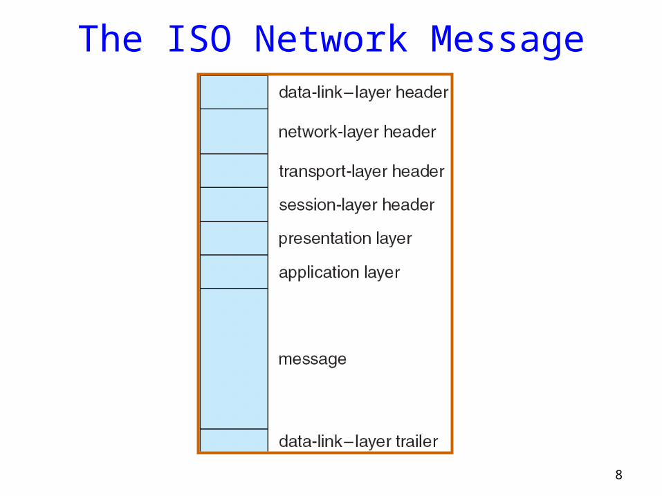
OSI Levels• Physical Layer
– electrical details of bits on the wire
• Data Link Layer– sending “frames” of bits and error detection
• Network Layer– routing packets to the destination
• Transport Layer– reliable transmission of messages, disassembly/assembly, ordering,
retransmission of lost packets
• Session Layer– really part of transport, typically Not implemented
• Presentation Layer– data representation in the message
• Application– high-level protocols (mail, ftp, etc.)

7
OSI Levels
Presentation
Transport
Network
Data Link
Physical
Application
Presentation
Transport
Network
Data Link
Physical
ApplicationNode A Node B
Network
Session Session
8
The ISO Network Message

9
The Internet Protocol Layers

10
Internet protocol stack
HTTP, SMTP, FTP, TELNET, DNS, …
TCP, UDP.
IP
Point-to-point links,LANs, radios, ...
Application
Transport
Network
Physical
usersnetwork
11
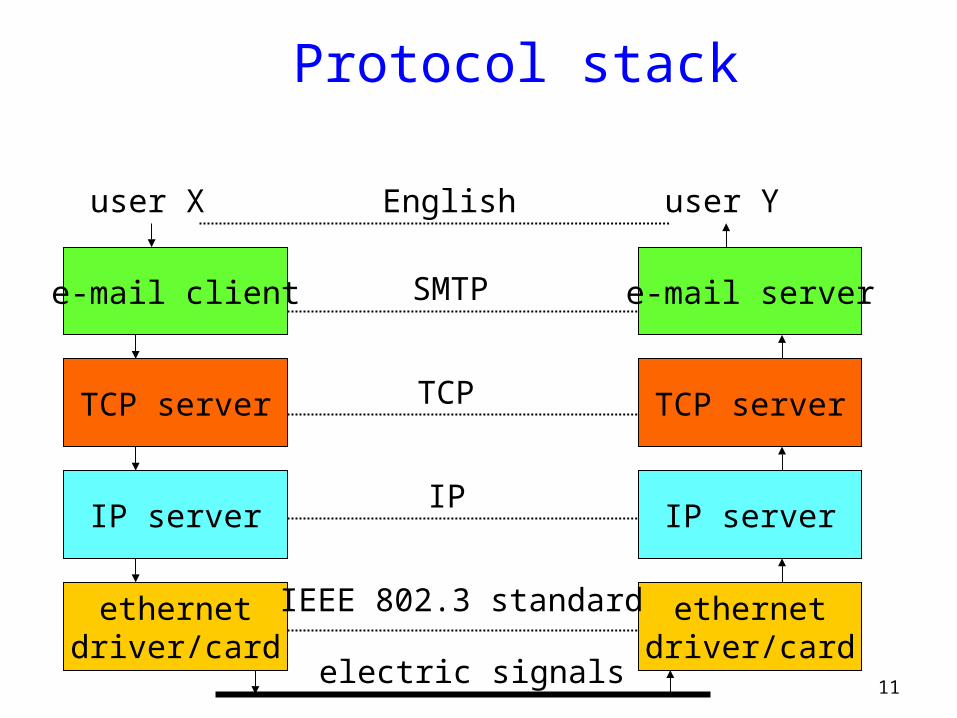
Protocol stack
e-mail client
TCP server
IP server
ethernetdriver/card
user X
SMTP
TCP
IP
e-mail server
TCP server
IP server
ethernetdriver/card
user Y
IEEE 802.3 standard
electric signals
English

12
Protocol interfaces
e-mail client
TCP server
IP server
ethernetdriver/card
user X
e-mail server
TCP server
IP server
ethernetdriver/card
user Y
s = open_socket();socket_write(s, buffer);…

13
Socket• A communication end-point unique to a machine
• An Internet socket is composed of the following:– Protocol (TCP, UDP, etc)– Local IP address
• Address of local machine
– Local port• Identifier for local process on local machine
– Remote IP address• Address of remote machine
– Remote port• Identifier for remote process on remote machine

14
Addressing• Each network interface has a hardware MAC address
– Multiple interfaces multiple addresses
• Each application communicates via a port– Port is a logical connection endpoint– Allows multiple local applications to use network resources– Up to 65,535
• < 1024 : used by privileged applications
• 1024 ≤ available for use ≤ 49151
• 49152 ≤ Dynamic ports/private ports ≤ 65535
– http ports 80 and 8080– ssh 20, telnet 23, ftp 21, etc
• Think of a telephone network …

15
Addressing and Packet Format
• The ``Data'' segment contains higher level protocol information.
– Which protocol is this packet destined for?
– Which process is the packet destined for?
– Which packet is this in a sequence of packets?
– What kind of packet is this?
• This is the stuff of the OSI reference model.
Start (7 bytes)
Destination (6)
Source (6)
Length (2)
Msg Data (1500)
Checksum (4)
16
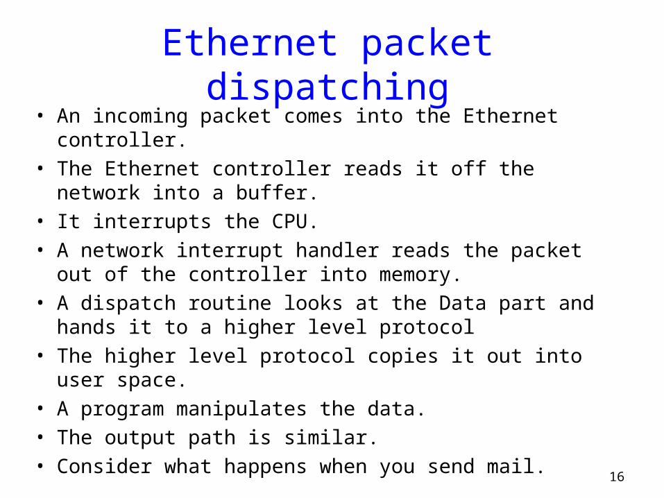
Ethernet packet dispatching• An incoming packet comes into the Ethernet controller.• The Ethernet controller reads it off the network into a
buffer.• It interrupts the CPU.• A network interrupt handler reads the packet out of the
controller into memory.• A dispatch routine looks at the Data part and hands it to a
higher level protocol• The higher level protocol copies it out into user space.• A program manipulates the data.• The output path is similar.• Consider what happens when you send mail.

17
Example: MailHi Dad.
Hi Dad.
To: Dad
SrcAddr: 128.95.1.2DestAddr: 128.95.1.3SrcPort: 110, DestPort: 110Bytes: 1-20
Hi Dad.
To: Dad
SrcEther: 0xdeadbeefDestEther: 0xfeedfaceSrcAddr: 128.95.1.2DestAddr: 128.95.1.3SrcPort: 100DestPort: 200Bytes: 1-20
Hi Dad.
To: Dad
Mail Composition And Display
Mail Transport Layer
Network Transport Layer
Link Layer
Network
User
Kernel
Hi Dad.
Hi Dad.
To: Dad
SrcAddr: 128.95.1.2DestAddr: 128.95.1.3SrcPort: 110, DestPort: 110Bytes: 1-20
Hi Dad.
To: Dad
SrcEther: 0xdeadbeefDestEther: 0xfeedfaceSrcAddr: 128.95.1.2DestAddr: 128.95.1.3SrcPort: 100DestPort: 200Bytes: 1-20
Hi Dad.
To: Dad

18
Protocol encapsulation
e-mail client
TCP server
IP server
ethernetdriver/card
user X
e-mail server
TCP server
IP server
ethernetdriver/card
user Y“Hello”
“Hello”
“Hello”
“Hello”
“Hello”

19
End-to-End Argument• What function to implement in each layer?• Saltzer, Reed, Clarke 1984
– A function can be correctly and completely implemented only with the knowledge and help of applications standing at the communication endpoints
– Argues for moving function upward in a layered architecture
• Should the network guarantee packet delivery ?– Think about a file transfer program– Read file from disk, send it, the receiver reads packets and writes
them to the disk

20
End-to-End Argument• If the network guaranteed packet delivery
– one might think that the applications would be simpler• No need to worry about retransmits
– But need to check that file was written to the remote disk intact
• A check is necessary if nodes can fail– Consequently, applications need to perform their retransmits
• No need to burden the internals of the network with properties that can, and must, be implemented at the periphery

21
End-to-End Argument• An Occam’s razor for Internet design
– If there is a problem, the simplest explanation is probably the correct one
• Application-specific properties are best provided by the applications, not the network– Guaranteed, or ordered, packet delivery, duplicate suppression,
security, etc.
• The internet performs the simplest packet routing and delivery service it can– Packets are sent on a best-effort basis– Higher-level applications do the rest

22
Two ways to handle networking• Circuit Switching
– What you get when you make a phone call– Dedicated circuit per call
• Packet Switching– What you get when you send a bunch of letters– Network bandwidth consumed only when sending– Packets are routed independently
• Message Switching– It’s just packet switching, but routers perform store-and-forward

23
Circuit Switching• End-to-end resources reserved for “call”
– Link bandwidth, switch capacity– Dedicated resources: no sharing– Circuit-like (guaranteed) performance– Call setup required
24
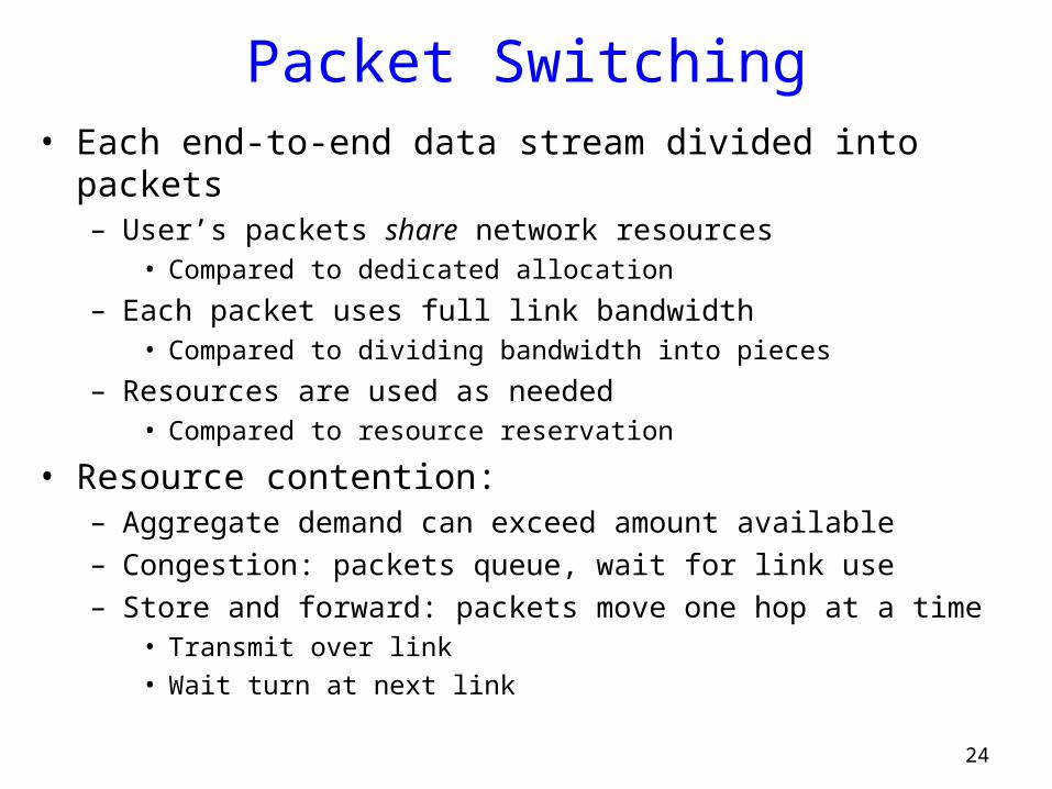
Packet Switching• Each end-to-end data stream divided into packets
– User’s packets share network resources• Compared to dedicated allocation
– Each packet uses full link bandwidth• Compared to dividing bandwidth into pieces
– Resources are used as needed• Compared to resource reservation
• Resource contention:– Aggregate demand can exceed amount available– Congestion: packets queue, wait for link use– Store and forward: packets move one hop at a time
• Transmit over link
• Wait turn at next link
25
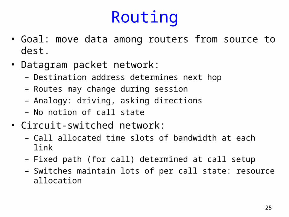
Routing• Goal: move data among routers from source to dest.• Datagram packet network:
– Destination address determines next hop– Routes may change during session– Analogy: driving, asking directions– No notion of call state
• Circuit-switched network:– Call allocated time slots of bandwidth at each link– Fixed path (for call) determined at call setup– Switches maintain lots of per call state: resource allocation

26
Packet vs. Circuit Switching• Reliability: no congestion, in-order data in circuit-switch• Packet switching: better bandwidth use• State, resources: packet switching has less state
– Good: less control plane processing resources along the way– More data plane (address lookup) processing
• Failure modes (routers/links down)– Packet switch reconfigures sub-second timescale– Circuit switching: more complicated
• Involves all switches in the path

27
A small Internet
A
V
R
B
W
r1,e1r2,e2
r3
a,e3
w,e5 b,e4
Scenario:A wants to send data to B.

28
Packet forwarding
HTTP
TCP
IP
ethernet
Host A
IP
eth
Router R
link
HTTP
TCP
IP
ethernet
Router W
Host B
IP
ethlink

29
Summary• Layering
– building complex services from simpler ones
• End-to-end argument– Application-specific properties are best provided by the applications,
not the network
• Packet vs Circuit Switching– Post card (packet) vs phone call (circuit)– Bandwidth and congestion
• Packet - better bandwidth usage, but potentially congested links
• Circuit - no congenstion, but potentially lower link utilization
– Failures and reconfiguration• Packet - Failed routed detected and routed around
• Circuit - reconfigure entire path if any router fails