introduction to raytracing raytracing introduction (from wikipedia) in computer graphics, ray...
TRANSCRIPT

Introduction to Raytracing
Raytracing Introduction (from Wikipedia)• In computer graphics, ray tracing is a technique for
generating an image by tracing the path of light through pixels in an image plane and simulating the effects of its encounters with virtual objects.
• The ray tracing algorithm builds an image by firing rays into a scene.
• Typically, each ray must be tested for intersection with some subset of all the objects in the scene.

Introduction to Raytracing
• Once the nearest object has been identified, the algorithm will estimate the incoming light at the point of intersection, examine the material properties of the object, and combine this information to calculate the final color of the pixel.

Introduction to Raytracing
The objective of a ray tracing program is to render a photo-realistic image of a virtual scene in 3 dimensional space.

Introduction to Raytracing
There are three major elements involved in the process:
1. The viewpoint: This is the location in 3-d space at which the viewer of the scene is located
2. The window: This defines a virtual window through which the viewer observes the scene. The window can be viewed as a discrete 2-D pixel array (pixmap) . The ray tracing procedure computes the color of each pixel. When all pixels have been computed, the pixmap is written out as a .ppm file
3. The scene: The scene consists of objects and light sources
| light light| obj
viewpt | obj| obj
| obj window

Coordinate Systems
Two coordinate systems will be involved and it will be necessary to map between them:
1. Window coordinates: the coordinates of individual pixels in the virtual window. These are two dimensional (x, y) integer numbers.– e.g., If a 400 col x 300 row image is being created, then the window's
x coordinates range from 0 to 399, and the window's y coordinates range from 0 to 299.
– In the ray tracing algorithm, a ray will be fired through each pixel in the window. The color of the pixels will be determined by the color of the object(s) the ray hits.
2. World coordinates: the “natural” coordinates of the scene measured in feet/meters etc. Since world coordinates describe the entire scene these coordinates are three dimensional (x, y, z) floating point numbers.

AssumptionsFor the sake of simplicity, we will assume that• The screen lies in the z = 0.0 plane• the center of the window has world
coordinates (0.0, 0,0, 0,0)• the lower left corner of the window
has window (pixel) coordinates (0, 0)• the location of the viewpoint has a
positive z coordinate• all objects have negative z
coordinates.

Coordinate Systems
"window" and coordinate systems
Translating from Pixel to World Coordinates
• In building a PPM image it is useful to think in terms of a screen with rows of pixels.
• Each pixel has a row index and a column index. The screen is 2-D as is this pixel coordinate system.
• In the virtual world it is useful to think in terms of a 3-D <x,y,z> coordinate that is measured in some units other than pixels. We will call this the "world" coordinate system.
• Every pixel has screen coordinates (the column and row index) and world coordinates. As we will see, we need some means to convert between the two coordinate systems. We can do this by noting the relationship between the screen’s pixel width and height and the screen’s world coordinates width and height.

Translating from Pixel to World Coordinates
As stated earlier, we will arbitrarily decide that the lower left pixel of the image is at screen coordinates <0, 0>, and the CENTER of the image is at world coordinates <0, 0, 0>. • For anything on the viewpoint side of the screen, the z
world coordinate will be positive, and • for objects behind the screen the z coordinate is negative. • These choices are intuitively natural.

Translating from Pixel to World Coordinates
To map a pixel's column index to the pixel’ s x coordinate in world coordinates we can use the following:
point_t world;
window_t *window = scene->window;
...
world.x = ((double)(column) / (double)(scene->picture->columns - 1)) *
window->windowWidth;
world.x -= window->windowWidth/2.0;
Where we assume "scene” is pointing to the initialized “scene_t” structure. Note the part of the equation in red computes the percent of the column width that the current column index represents.
When we multiply this percent by the width of the image in world coordinates, we get the distance from the left edge of the image in world coordinates.
Finally, since the x coordinate of the middle of the image is 0, we subtract away half of the image width (i.e. the x world coordinate for a pixel in the left half of the window is negative, and positive is the right half).
The computation of the y coordinate is similar. For all pixels the z coordinate is 0.

Translating from Pixel to World Coordinates
• Example: Suppose the window is 640 pixels wide x 480 pixels high, and the dimensions of the window in world coordinates is 8 ft wide by 6 ft high. Find the world coordinates of the pixel at column 100, row 40.
• Solution: – Compute the fraction or percentage of the complete x size that must
be traversed to reach column 100 100/(640 -1)– Therefore,
world.x = 100/639 * 8 ft 1.25 ft.
world.x = world.x - 8/2 1.25 - 4.0 or -2.75– Similarly, for the world.y = 40/479 * 6 ft 0.5
world.y = world.y - 6/3 0.5 - 3.0 or -2.5– world.z = 0. Why?
(Because the screen lies in the z = 0 plane, thus the z coordinate of every point in the window is 0.0!)
– So the world coordinates of the pixel are (-1.25, -2.5, 0)

Computing the Number of Rows in the Output Image
• We will find that the input data will provide us with the scene dimensions, and the number of pixel columns. From this we can compute the number of pixel rows in the output image.
• So in the scene_t, the fields sceneHeight and sceneWidth will have known values.
• Also in the scene_t the pixelColumns field has a known value.

Computing the Number of Rows in the Output Image
• Note that the following ratios are equal:
rows/pixelColumns = windowHeight/windowWidth
• So we can compute rows as:
rows = (windowHeight/windowWidth)*pixelColumns
• We will see later that the value of rows in the image_t will be computed in a procedure called “completeScene()”, and the values of the rows and columns field will be used to malloc space for the output image.

The genRay() function
• The genRay() function creates a unit vector from the viewpoint to a pixel.
• We will use this function to create a unit vector from the viewpoint towards every pixel, and then ask the question “did we hit anything?”

The genRay() function
The function has the prototype:
vector_t genRay(scene_t *scene, int column, int row);
where scene points to the scene_t, and column and row are the pixel’s pixel coordinates
<column, row>.

The genRay() function
The function should return a unit vector that goes in the direction from the viewpoint to the pixel at pixel coordinates <column, row>. The procedure should:
1. convert the pixel coordinates <column, row> to their corresponding world coordinates <x, y, z>. The procedure for computing x was described in the previous section. The procedure for computing y is similar. For all pixels z will be 0 (why?).
2. generate a vector from the viewpoint coordinates to the pixel’s coordinates. Recall that this is readily done using the ray() function. The vector will not necessarily be a unit vector.
3. convert the vector to a unit vector
4. return the unit vector.

Additional ray tracer data types
• In the ray tracer we have many instances of wanting to use vectors. In lab 3 we created a library of functions that manipulate vectors. For the sake of readability in our code we will use typedef’s to define additional data types that are all equivalent to a vector_t, e.g.:
typedef vector_t point_t;
typedef vector_t intensity_t;

Additional ray tracer data types
• The pixel_t defines the (r, g, b) fields of a pixel as we have used in previous home works,
• i.e.:
typedef struct pixel_type {
unsigned char r;
unsigned char g;
unsigned char b;
} pixel_t;• Note that for an intensity_t the RGB values equate to the x,
y and z components of the tuple_t structure, which of course are 3 double precision numbers. We will see later how the use of an intensity_t differs from a pixel_t, which is 3 eight-bit integer values ranging from 0 to 255.

The ray tracing algorithm
Phase 1: Initialization– Acquire input SDL filename and output ppm filename from the
command line– Process the scene description language (SDL)– print scene data to the stderrr
Phase 2: The ray tracing procedure for building the screen image{
– initialize the color of the pixel to (0, 0, 0)– compute the world coordinates of the pixel– compute the direction in 3-d space of a ray from the viewpoint
through the pixel– identify the first (closest) object hit by the ray– compute the color of the pixel based upon the illumination of
the object(s)
}

The ray tracing algorithm
Phase 3: Writing out the image_t as a .ppm file– write .ppm header to output ppm file– write the image to output ppm file
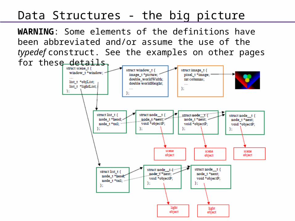
Data Structures - the big pictureWARNING: Some elements of the definitions have been abbreviated and/or assume the use of the typedef construct. See the examples on other pages for these details.

The main function
• A properly designed and constructed program is necessarily modular in nature. Modularity is somewhat automatically enforced in O-O languages, but new C programmers often revert to an ugly pack- it- all- into- one-main- function approach.
• To discourage this in the program, the design will avoid:
1 - Functions that are too long (greater than 30 lines)
2 - Nesting of code greater than 2 deep
3 - Lines that are too long (greater than 80 characters)

The main function
• Here is the main function for the final version of the ray tracer.int main(int argc, char *argv[])
{open model description language (SDL) input file and the output image PPM fileProcess the scene description language file and build the scene data structuresPrint the scene data (for debugging purposes)Create the imageOutput the ppm imagereturn 0;
}