introduction to robotics (fag 3480) · introduction to robotics (fag 3480) vår 2011 robert wood...
TRANSCRIPT

Introduction to Robotics (Fag 3480)Vår 2011
Robert Wood (Harward Engineeering and Applied Sciences-Basis)Ole Jakob Elle, PhD (Modified for IFI/UIO)
Førsteamanuensis II, Institutt for InformatikkUniversitetet i Oslo
Seksjonsleder Teknologi, Intervensjonssenteret, Oslo Universitetssykehus (Rikshospitalet)
Fag 3480 - Introduction to Roboticsside 2
Ch. 3: Forward and Inverse Kinematics

Fag 3480 - Introduction to Roboticsside 3
Recap: The Denavit-Hartenberg (DH) Convention
Representing each individual homogeneous transformation as the product of four basic transformations:
−
−
=
−
−
=
=
10000
100000000001
100001000010
001
1000100
00100001
100001000000
,,,,
i
i
i
i
i
xaxdzzi
dcssascccscasscsc
cssc
a
dcssc
A
ii
iiiiii
iiiiii
ii
iiii
ii
iiii
αα
θαθαθθ
θαθαθθ
αα
ααθθ
θθ
αθ RotTransTransRot

Fag 3480 - Introduction to Roboticsside 4
Recap: the physical basis for DH parametersai: link length, distance between the o0 and o1 (projected along x1)
αi: link twist, angle between z0 and z1 (measured around x1)
di: link offset, distance between o0 and o1 (projected along z0)
θi: joint angle, angle between x0 and x1 (measured around z0)

Fag 3480 - Introduction to Roboticsside 5
General procedure for determining forward kinematics• Label joint axes as z0, …, zn-1 (axis zi is joint axis for joint i+1)
• Choose base frame: set o0 on z0 and choose x0 and y0 using right-handed convention
• For i=1:n-1,
• Place oi where the normal to zi and zi-1 intersects zi. If zi intersects zi-1, put oi at intersection. If zi and zi-1 are parallel, place oi along zi such that di=0
• xi is the common normal through oi, or normal to the plane formed by zi-1 and zi if the two intersect
• Determine yi using right-handed convention
• Place the tool frame: set zn parallel to zn-1
• For i=1:n, fill in the table of DH parameters
• Form homogeneous transformation matrices, Ai
• Create Tn0 that gives the position and orientation of the end-effector in the inertial
frame

Fag 3480 - Introduction to Roboticsside 6
Example 2: three-link cylindrical robot
3DOF: need to assign four coordinate frames
Choose z0 axis (axis of rotation for joint 1, base frame)
Choose z1 axis (axis of translation for joint 2)
Choose z2 axis (axis of translation for joint 3)
Choose z3 axis (tool frame)
This is again arbitrary for this case since we have described no wrist/gripper
Instead, define z3 as parallel to z2

Fag 3480 - Introduction to Roboticsside 7
Example 2: three-link cylindrical robot
Now define DH parameters
First, define the constant parameters ai, αi
Second, define the variable parameters θi, di
link ai αi di θi
1 0 0 d1 θ1
2 0 -90 d2 0
3 0 0 d3 0
=
−=
−
=
1000100
00100001
1000010
01000001
1000100
0000
33
22
1
11
11
1 dA
dA
dcssc
A , ,
+−
−−
==
1000010
00
21
3111
3111
3210
3 dddccsdssc
AAAT

Fag 3480 - Introduction to Roboticsside 8
Example 3: spherical wrist3DOF: need to assign four coordinate frames
yaw, pitch, roll (θ4, θ5, θ6) all intersecting at one point o (wrist center)
Choose z3 axis (axis of rotation for joint 4)
Choose z4 axis (axis of rotation for joint 5)
Choose z5 axis (axis of rotation for joint 6)
Choose tool frame:
z6 (a) is collinear with z5
y6 (s) is in the direction the gripper closes
x6 (n) is chosen with a right-handed convention

Fag 3480 - Introduction to Roboticsside 9
Example 3: spherical wristlink ai αi di θi
4 0 -90 0 θ4
5 0 90 0 θ5
6 0 0 d6 θ6
Now define DH parameters
First, define the constant parameters ai, αi
Second, define the variable parameters θi, di
−
=
−
−
=
−
−
=
1000100
0000
100000100000
100000100000
6
66
66
655
55
544
44
4 dcssc
Acssc
Acssc
A , ,
−+−+−−−
==
10006556565
654546465464654
654546465464654
6543
6 dcccscsdssssccscsscccsdscsccssccssccc
AAAT

Fag 3480 - Introduction to Roboticsside 10
Example 4: cylindrical robot with spherical wrist
6DOF: need to assign seven coordinate frames
But we already did this for the previous two examples, so we can fill in the table of DH parameters:
link ai αi di θi
1 0 0 d1 θ1
2 0 -90 d2 0
3 0 0 d3 0
4 0 -90 0 θ4
5 0 90 0 θ5
6 0 0 d6 θ6
o3, o4, o5 are all atthe same point oc

Fag 3480 - Introduction to Roboticsside 11
Example 4: cylindrical robot with spherical wristNote that z3 (axis for joint 4) is collinear with z2 (axis for joint 3),
thus we can make the following combination:
==
1000333231
232221
131211
36
03
06
z
y
x
drrrdrrrdrrr
TTT
21654
316516541
316516541
5433
5154123
5154113
6465432
651641654122
651641654112
6465431
651641654121
651641654111
dddssddcdccdscsddsdcsdsccd
ssrccscsrcssccrccccsr
cscssssccsrcsscscscccr
scccsrcscssscccsrcsssscccccr
z
y
x
++−=
++=
−−=
−=
+=
−=
−=
+−−=
−−−=
−−=
−−=
+−=

Fag 3480 - Introduction to Roboticsside 12
Example 5: the Stanford manipulator
6DOF: need to assign seven coordinate frames:
Choose z0 axis (axis of rotation for joint 1, base frame)
Choose z1-z5 axes (axes of rotation/translation for joints 2-6)
Choose xi axes
Choose tool frame
Fill in table of DH parameters:
link ai αi di θi
1 0 -90 0 θ1
2 0 90 d2 θ2
3 0 0 d3 0
4 0 -90 0 θ4
5 0 90 0 θ5
6 0 0 d6 θ6

Fag 3480 - Introduction to Roboticsside 13
Example 5: the Stanford manipulatorNow determine the individual homogeneous
transformations:
−
=
−−
=
−
−
=
=
−
=
−
−
=
1000100
0000
100000100000
100000100000
1000100
00100001
1000010
0000
100000100000
6
66
66
655
55
544
44
4
33
2
22
22
211
11
1
dcssc
Acs
sc
Acssc
A
dA
dcs
sc
Acssc
A
, ,
, ,

Fag 3480 - Introduction to Roboticsside 14
Example 5: the Stanford manipulatorFinally, combine to give the complete
description of the forward kinematics:
=⋅⋅⋅=
1000333231
232221
131211
610
6z
y
x
drrrdrrrdrrr
AAT
( )[ ] ( )( )[ ] ( )( )
( )[ ] ( )( )[ ] ( )
( )( )( )
( )( )
( )52452632
2155142541621321
5412515421621321
5254233
54152542123
54152542113
65264654232
646541652646542122
646541652646542112
65264654231
646541652646542121
646542652646542111
sscccddcdsscssccsscddcdssdssssccscccddsdscd
ccscsrssccssccsrssscsscccrssccssccsr
scscscssscsscccsrccscssssscssccccr
cscsscccsrscccsccssssccccsrscccsdcsssscccccr
z
y
x
−+=
++++=
−++−=
+−=
++=
−+=
++=
+−+−−−−=
+−−++−=
−−−=
++−−=
+−−−=

Fag 3480 - Introduction to Roboticsside 15
Example 6: the SCARA manipulator
4DOF: need to assign five coordinate frames:
Choose z0 axis (axis of rotation for joint 1, base frame)
Choose z1-z3 axes (axes of rotation/translation for joints 2-4)
Choose xi axes
Choose tool frame
Fill in table of DH parameters:
link ai αi di θi
1 a1 0 0 θ1
2 a2 180 0 θ2
3 0 0 d3 0
4 0 0 d4 θ4

Fag 3480 - Introduction to Roboticsside 16
Example 6: the SCARA manipulator
Now determine the individual homogeneous transformations:
−
=
=
−−
=
−
=
1000100
0000
1000100
00100001
10000100
00
10000100
00
4
44
44
43
32222
2222
21111
1111
1 dcssc
Ad
Asacscasc
Asacscasc
A , , ,
−−−+−−−++−+
=⋅⋅⋅=
1000100
00
43
12211412412412412
12211412412412412
410
4 ddsasaccsssccscacacsscsscc
AAT

Fag 3480 - Introduction to Roboticsside 17
Industrial robotsHigh precision and repetitive tasks
Pick and place, painting, etc
Hazardous environments

Fag 3480 - Introduction to Roboticsside 18
Common configurations: elbow manipulatorAnthropomorphic arm: ABB IRB1400 or KUKA
Very similar to the lab arm NACHI (RRR)

Fag 3480 - Introduction to Roboticsside 19
Simple example: control of a 2DOF planar manipulator
Move from ‘home’ position and follow the path AB with a constant contact force F all using visual feedback

Fag 3480 - Introduction to Roboticsside 20
Coordinate frames & forward kinematicsThree coordinate frames:
Positions:
Orientation of the tool frame:0 1
2
( )( )
=
11
11
1
1
sincos
θθ
aa
yx
( ) ( )( ) ( ) ty
xaaaa
yx
≡
++++
=
21211
21211
2
2
sinsincoscos
θθθθθθ
0 1 2
+++−+
=
⋅⋅⋅⋅
=)cos()sin()sin()cos(
ˆˆˆˆˆˆˆˆ
2121
2121
0202
020202 θθθθ
θθθθyyyxxyxx
R
=
=
10ˆ
01ˆ 00 yx ,
++−
=
++
=)cos()sin(ˆ
)sin()cos(ˆ
21
212
21
212 θθ
θθθθθθ
yx ,

Fag 3480 - Introduction to Roboticsside 21
Inverse KinematicsFind the values of joint parameters that will put the tool frame at a desired
position and orientation (within the workspace)
Given H:
Find all solutions to:
Noting that:
This gives 12 (nontrivial) equations with n unknowns
( )310
SEoR
H ∈
=
( ) HqqT nn =,...,10
( ) ( ) ( )nnnn qAqAqqT ⋅⋅⋅= 1110 ,...,

Fag 3480 - Introduction to Roboticsside 22
For a given H:
Find θ1, θ2, d3, θ4, θ5, θ6:
One solution: θ1 = π/2, θ2 = π/2, d3 = 0.5, θ4 = π/2, θ5 = 0, θ6 = π/2
−
=
10000001763.0100154.0010
H
Example: the Stanford manipulator
( )[ ] ( )( )[ ] ( )
( )( )[ ] ( )( )[ ] ( )
( )( )( )
( )( )
( ) 0763.0
154.0010001100
52452632
2155142541621321
5412515421621321
52542
541525421
541525421
652646542
6465416526465421
6465416526465421
652646542
6465416526465421
6465426526465421
=−+
=++++
−=−++−
=+−
=++
=−+
=++
=+−+−−−−
=+−−++−
=−−−
=++−−
=+−−−
sscccddcsscssccsscddcdssssssccscccddsdscccscsssccssccsssscsscccssccssccs
scscscssscsscccsccscssssscsscccccscsscccsscccsccssssccccsscccsdcssssccccc

Fag 3480 - Introduction to Roboticsside 23
Inverse Kinematics• The previous example shows how difficult it would be to obtain a closed-form
solution to the 12 equations
• Instead, we develop systematic methods based upon the manipulator configuration
• For the forward kinematics there is always a unique solution
• Potentially complex nonlinear functions
• The inverse kinematics may or may not have a solution
• Solutions may or may not be unique
• Solutions may violate joint limits
• Closed-form solutions are ideal!
Fag 3480 - Introduction to Roboticsside 24
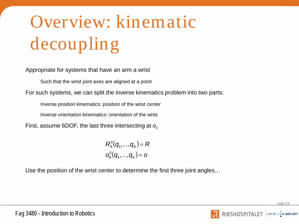
Overview: kinematic decoupling
Appropriate for systems that have an arm a wrist
Such that the wrist joint axes are aligned at a point
For such systems, we can split the inverse kinematics problem into two parts:
Inverse position kinematics: position of the wrist center
Inverse orientation kinematics: orientation of the wrist
First, assume 6DOF, the last three intersecting at oc
Use the position of the wrist center to determine the first three joint angles…
( )( ) oqqo
RqqR
=
=
6106
6106
,...,,...,

Fag 3480 - Introduction to Roboticsside 25
Overview: kinematic decoupling
Now, origin of tool frame, o6, is a distance d6 translated along z5 (since z5 and z6 are collinear)
Thus, the third column of R is the direction of z6 (w/ respect to the base frame) and we can write:
Rearranging:
Calling o = [ox oy oz]T, oc0 = [xc yc zc]T
+==
100
606 Rdooo o
c
−=
100
6Rdoooc
−−−
=
336
236
136
rdordordo
zyx
z
y
x
c
c
c

Fag 3480 - Introduction to Roboticsside 26
Overview: kinematic decoupling
Since [xc yc zc]T are determined from the first three joint angles, our forward kinematics expression now allows us to solve for the first three joint angles decoupled from the final three.
Thus we now have R30
Note that:
To solve for the final three joint angles:
Since the last three joints for a
spherical wrist, we can use a set of
Euler angles to solve for them
36
03RRR =
( ) ( ) RRRRR T03
103
36 ==
−

Fag 3480 - Introduction to Roboticsside 27
Inverse positionNow that we have [xc yc zc]T we need to find q1,
q2, q3
Solve for qi by projecting onto the xi-1, yi-1 plane, solve trig problem
Two examples: elbow (RRR) and spherical (RRP) manipulators
For example, for an elbow manipulator, to solve for θ1, project the arm onto the x0, y0 plane

Fag 3480 - Introduction to Roboticsside 28
Background: two argument atanWe use atan2(·) instead of atan(·) to account for the
full range of angular solutions
Called ‘four-quadrant’ arctan
( )
( )
==
=>
≥≥
<≥
−−
<−−
=
0,0
0,02
0,0
0,0
0,2
,2
xy
xy
xyxy
xyxy
yxy
xy
undefined
atan
atan
atan
atan
π
π

Fag 3480 - Introduction to Roboticsside 29
Example: RRR manipulatorTo solve for θ1, project the arm onto the x0, y0 plane
( )cc yx ,21 atan=θ
( )cc yx ,21 atan+= πθ

Fag 3480 - Introduction to Roboticsside 30
If there is an offset, then we will have two solutions for θ1: left arm and right arm
However, wrist centers cannot intersect z0
If xc=yc=0, θ1 is undefined
i.e. any value of θ1 will work
Caveats: singular configurations, offsets

Fag 3480 - Introduction to Roboticsside 31
Left arm: Right arm:
Left arm and right arm solutions
( )
−+=
==
ddyx
yx
cc
cc
,2
,2222
1
atan
atan-
α
φαφθ ( )
−−+−=
−++=
=+=
ddyx
ddyx
yx
cc
cc
cc
,2
,2
,2
222
222
1
atan
atan
atan
πβ
αβαθ

Fag 3480 - Introduction to Roboticsside 32
Therefore there are in general two solutions for θ1
Finding θ2 and θ3 is identical to the planar two-link manipulator we have seen previously
Therefore we can find two solutions for θ3:
Left arm and right arm solutions
( ) Daa
aadzdyx
dzsdyxr
aaaasr
ccc
c
cc
≡−−−+−+
=⇒
−=
−+=
−−+=
32
23
22
21
222
3
1
2222
32
23
22
22
3
2cos
2cos
θ
θ
( )23 1,2 DD −±= atanθ

Fag 3480 - Introduction to Roboticsside 33
The two solutions for θ3 correspond to the elbow-down and elbow-up positions respectively
Now solve for θ2:
Thus there are two solutions for the pair (θ2, θ3)
Left arm and right arm solutions
( ) ( )( )333321
222
333322
,2,2
,2,2
sacaadzdyx
sacaasr
ccc +−
−−+=
+−=
atanatan
atanatanθ

Fag 3480 - Introduction to Roboticsside 34
In general, there will be a maximum of four solutions to the inverse position kinematics of an elbow manipulator
Ex: PUMA
RRR: Four total solutions

Fag 3480 - Introduction to Roboticsside 35
Spherical configuration
Solve for θ1 using same method as with RRR
Again, if there is an offset, there
will be left-arm and right-arm solutions
Solve for θ2:
Solve for d3:
Example: RRP manipulator
( )cc yx ,21 atan=θ
( )
1
222
2 ,2
dzsyxr
rs
c
cc
−=
+=
= atanθ
( )2122
223
dzyx
srd
ccc −++=
+=

Fag 3480 - Introduction to Roboticsside 36
Next class…Complete the discussion of inverse kinematics
Inverse orientation
Introduction to other methods
Introduction to velocity kinematics and the Jacobian